
Dye-Sensitized Photocatalytic Water Splitting and Sacrificial Hydrogen Generation: Current Status and Future Prospects


1
Department of Chemical and Biochemical Engineering, Western University, London, ON N6A 5B9, Canada
2
Trojan Technologies, London, ON N5V 4T7, Canada
*
Author to whom correspondence should be addressed.
Inorganics 2017, 5(2), 34; https://doi.org/10.3390/inorganics5020034
Submission received: 16 March 2017
/
Revised: 27 April 2017
/
Accepted: 6 May 2017
/
Published: 18 May 2017
(This article belongs to the Special Issue Photochemical Water Splitting)
Abstract
:Today, global warming and green energy are important topics of discussion for every intellectual gathering all over the world. The only sustainable solution to these problems is the use of solar energy and storing it as hydrogen fuel. Photocatalytic and photo-electrochemical water splitting and sacrificial hydrogen generation show a promise for future energy generation from renewable water and sunlight. This article mainly reviews the current research progress on photocatalytic and photo-electrochemical systems focusing on dye-sensitized overall water splitting and sacrificial hydrogen generation. An overview of significant parameters including dyes, sacrificial agents, modified photocatalysts and co-catalysts are provided. Also, the significance of statistical analysis as an effective tool for a systematic investigation of the effects of different factors and their interactions are explained. Finally, different photocatalytic reactor configurations that are currently in use for water splitting application in laboratory and large scale are discussed.
1. Introduction
Global energy systems transition shows a clear energy shift from coal to oil to hydrogen (Figure 1) [1]. The element hydrogen is found in abundance in the universe—in water, life forms, and hydrogen fuel. The three major issues, among different driving forces that contribute to the energy transition towards hydrogen, are (i) growing requirement for energy; (ii) insufficiency of oil in the immediate future and (iii) possibilities of climate change. By 2050 the expected energy demand will be doubled as world population grows to 10 billion. Coal and oil are promising energy sources, but we need some other energy sources as well that are present in much larger quantities and can meet the future energy demand [2].
Human activity, approximately, produces 6 billion tons of carbon dioxide annually, with 80% coming from the burning of the fossil fuels. Coal generates 430 g of CO2/kWh, while natural gas produces 190 g of CO2/kWh [3]. The atmospheric CO2 level of 270 ppm during industrial revolution rose to 370 ppm during the 20th century, and the current level of CO2 is 406 ppm [4].
Currently, most hydrogen is produced and used by chemical and petroleum industries through natural gas reforming, coal gasification, thermal water splitting, and electrolysis. About 96% of worlds’ hydrogen is currently produced from natural gas, oil or coal (48% from natural gas, 30% from oil, 18% from coal, and the remaining 4% via water electrolysis) [3]. These processes require big infrastructure, significant energy sources and run enormous environmental cost. Furthermore, if hydrogen is not generated on-site, a greater quantity of energy is needed to distribute the element. Biomass could also be used to produce hydrogen, but the basic feedstock is inadequate and would also need large energy input [2,3,5].
The most promising technology for hydrogen generation from renewable water and sunlight would be photocatalytic water splitting. Fujishima and Honda demonstrated water splitting in the early 1970s, with a TiO2 photoanode and Pt cathode in the presence of UV light irradiation. Additionally, a power supply or pH difference between a catholyte and an anolyte were used to apply some external bias to the above process [6]. The last few decades saw a notable progress in this research area using UV light [7]. The elements of group IV (Ti and Zr), group V (Nb and Tc) and group VI (W) acted as wide band gap photocatalytic materials for water splitting. In spite of such development over time, photocatalytic systems for water splitting as well as hydrogen generations are still experiencing many technical challenges. The narrow wavelength range of UV light is its fundamental difficulty, and therefore utilization of the more profuse visible light for photocatalytic reactions appears to be a promising alternative [2].
Dye-sensitization is an innovative technology that could play a major role in developing an efficient and cost-effective visible light active semiconductor photocatalyst in the near future. Dye-sensitization technology, so far, has been used in solar cell research to generate electricity. Presently, dye-sensitization processes also found applications in visible-light-assisted photocatalytic water splitting to produce hydrogen. Several authors have used numerous dyes such as porphyrins, coumarin, phthalocyanines and carboxylate derivatives of anthracene to sensitize different semiconductor photocatalysts. Among the various photosensitizers, transition metal-based sensitizers have been shown to be the best. Transition metals such as Ru(II), Fe(II) and Os(II) form d6 complex and undertake strong charge transfer absorption throughout the visible range [8]. Ru(II) polypyridine complexes are mostly applied in dye-sensitized solar cells. In the field of dye-sensitized solar cell, Gratzel stated cis-[Ru(dcbH2)2(NCS)2] (N3), as the best sensitizer, where thiocyanate (NCS−) was applied as an ancillary ligand [9].
In the case of photocatalytic overall water splitting/sacrificial hydrogen generation, researchers have widely used different organic dyes, inorganic sensitizers, and coordination metal complexes. The toxicity and high cost of Ruthenium-based dyes make them uneconomical in industrial applications. On the other hand, organic dyes are less toxic, low-cost, and can be used for large-scale dye sensitization processes. Several organic dyes such as Eosin Y, Rose Bengal, Merocyanine, Cresyl violet and Riboflavin have been employed for spectral sensitization of semiconductors photocatalysts [10,11].
We begin the review with the explanation of thermodynamics and kinetics of water splitting processes. Then we focus on the research progresses on visible-light-assisted overall water splitting and sacrificial hydrogen generation with photocatalytic and photoelectrochemical systems. Basic phenomena of dye-sensitization are well described here in the areas mentioned above. The review also elucidates the usefulness of design of experiment as an effective tool for photocatalytic hydrogen generation studies. Finally, we discuss different photocatalytic reactor configurations that are either in use or will be applied in future in photocatalytic water splitting and hydrogen generation systems.
2. Photocatalytic/Photoelectrochemical Water Splitting: Thermodynamics and Kinetics
Salvador systematically explained the general photocatalytic water splitting reaction scheme in the presence of a semiconductor photocatalyst (Equations (1)–(4)) [12]. Upon illumination of light with photon energy greater than or equal to the bandgap energy of the semiconductor, electrons, and holes are generated in conduction and valence bands of the semiconductor, respectively. The charge carriers finally oxidize and/or reduce water molecules producing gaseous hydrogen and oxygen in 2:1 stoichiometric ratio by volume (Figure 2) [13]. Operating principle of photo-electrolytic water splitting in the photoelectrochemical cell is quite similar to the photocatalytic water splitting (Figure 3) [13]. At the interface between the electrolyte and photo electrode, the photo-generated holes react with water to generate gaseous oxygen and hydrogen ion (H+). The photo-generated electrons flow through the external circuit to the photocathode, captured by the hydrogen ion at the photocathode-electrolyte boundary and produce hydrogen gas.
Photocatalytic water splitting reaction scheme:
2.1. Thermodynamics of Water Splitting
The photon energy is transformed into chemical energy through water splitting giving a positive value of Gibbs free energy. On the other hand, photocatalytic degradation reactions are downhill reactions. This downhill-type reaction is known as a photoinduced reaction and has been widely studied using TiO2 photocatalysts [6]. At standard conditions, electrolysis of water reversibly produces a stoichiometric mixture of hydrogen and oxygen (2:1) at a potential of 1.23 V which is obtained from the equation of Gibbs free energy:
where, ∆Go is standard Gibbs free energy change, n is the number of electrons, F is Faraday’s constant and ∆Eo is the standard electrical potential of the reaction. The electromotive force or EMF (∆E) is defined as the maximum potential difference of an electrochemical reaction [3].
The Gibbs free energy change (∆G) at STP is positive for an endothermic process such as water splitting reaction (Equation (4)). Such a non-spontaneous reaction will only occur if adequate energy is provided by the incident photons. The standard Gibbs free energy change (∆Go) is the negative value of maximum electrical work corresponding to 237.14 kJ·mol−1 or 2.46 eV for Equation (4). Since this is a two-electron redox process, photocatalytic water splitting is possible if the semiconductor photocatalyst possesses a band gap energy (Eg) greater than 1.23 eV [3,14].
The two energetic requirements for reactions (2) and (3) to take place spontaneously are:
where, En*, Ep* are the individual energies of photo-generated electrons and holes respectively. It is assumed that after thermalization within the semiconductor bands En* and Ep* reach energy levels near Ev (valence band energy) and Ec (conduction band energy), respectively [12]. According to Equations (6) and (7) the energy of photoelectrons must be above the energy level of the (H2O/H2) redox couple and the energy of photo holes below the energy level of the (O2/H2O) redox couple. This is shown in the following equations:
Now in the absence of any over potential, the minimum semiconductor band gap is given by Equation (9):
2.2. Kinetic Constraint of Water Splitting
The kinetic requirement of water splitting reaction is very well explained by Salvador [12]. In this section, we are mainly presenting his ideas in modifying the band gap energy. In Equation (9) he has not considered the overpotential for oxygen (ηO2) and hydrogen (ηH2) evolution, the energy difference between EC and EF (energy of equilibrium Fermi level at dark) and electrolyte resistance (ηR). Thus, the revised equation for band gap energy (Eg) would be as follows:
All these over potential values are maintained on the lower side to minimize the band gap energy. The oxygen over potential control is slightly difficult than the other factors. In electrolytic oxygen evolution on metals, at first chemisorbed water molecule reacts with a hole (h+) and generate radical which is not applicable for semiconductors. A water molecule can more easily inject electrons into the semiconductor VB (valence band) under illumination when they are chemisorbed since electron transfer can then happen directly without the necessity of a tunneling process [12]. If we consider the energy diagram of semiconductor and electrolyte levels, we will see that the upper level of water VB (4.65 eV), is below E(H2O/H2), i.e., for water splitting Eg ≥ 4.65 eV. Again, photogeneration of hole occurs at the upper level of the semiconductor VB which is then transferred to filled extrinsic level of solvated HO− ions. Then Eg ≥ E(H2O/H2) − E(HO•/HO−) = 2.80 eV. In both cases, the band gap energy (Eg) shows much higher value than the optimum Eg value [12].
To avoid such limitations, the following reaction scheme was considered:
where, s denotes the surface adsorbed species; M denotes transition metals surface to which water and intermediate species are organized. Here water molecules are chemisorbed, and holes can be captured inelastically by band gap surface states associated with water molecules [12]. Reaction (12) is possible if the following energy criterion is achieved:
where, Ea is the energy of activation which is basically the reorganization energy (Ψ) of the E(HO•/HO−)s redox couple. If the HO− is strongly adsorbed onto the semiconductor surface then the interaction with the surrounding water molecule will be less and Ψ value will be low, which ultimately reduces the overpotential for the Reaction (12). The shift of E(HO•/HO−)s in the adsorbed state with respect to the same couple in the aqueous phase is given by:
Therefore, if the interaction with the semiconductor of both oxidation states of the redox couple (HO• and HO− species) is the same [i.e., ΔGads(HO•) = ΔGads(HO−)], the redox potential of the system in the adsorbed state will be the same as in the solution [12].
3. Visible-Light-Driven Overall Water Splitting/Sacrificial Hydrogen Generation
Fujishima and Honda described the photocatalytic water splitting over a TiO2 single crystal in 1972 [15]. After that, a remarkable progress on water splitting has been observed in the last few decades under UV light [7,16]. The basic problem with UV photocatalysis was a 4% solar spectrum compared to visible light (46%). We know that the band gap energy (Eg) > 1.23 eV for photocatalytic water splitting from the thermodynamic point of view. Now the semiconductor photocatalyst will be visible light active if the band gap energy is <3.0 eV. The photocatalytic materials for visible light water splitting should possess a suitable band gap energy (1.23 eV < Eg < 3.0 eV). Also the band position of the semiconductor plays a significant role in visible light excitation of the photocatalyst [14]. Photocatalysts such as TiO2, ZnO, and SnO2 have large band gaps (3–3.8 eV) and utilize only UV portion of the solar light, and therefore displays low conversion efficiencies. Figure 4 shows band positions of several semiconductor photocatalysts in contact with aqueous electrolyte at pH 1 [3]. Only a few chalcogenides (CdS, CdSe, etc.) have a band gaps between 1.23 eV and 3.0 eV, which can be stimulated by visible light. However, these photocatalysts cannot be used because of the severe photo-corrosion problem. Currently, the energy conversion efficiency from solar to hydrogen through photocatalytic water splitting is very low. This is primarily for two reasons: (i) rapid recombination of the charge carriers; and (ii) inability to utilize visible solar radiation. Different approaches have been applied to modify the photocatalyst to make them visible light active. Some popular approaches include doping with cation/anion, valence band controlled photocatalyst, composite photocatalyst, spectral-sensitization (dye-sensitization) and metal ion implantation [17]. Table 1 shows a comparative study of different photocatalyst modification methods along with their advantages and limitations.
The following section will discuss the basics and finer details of dye-sensitization processes in photoelectrochemical and photocatalytic water splitting.
4. Dye-Sensitization Process: Visible Light Active Photocatalyst
The process of enlarging the photocatalytic activity of semiconductor to the visible region is identified as spectral sensitization. In the case of dye-sensitization, the sensitization of a large band gap semiconductor is accomplished with a dye [29]. The history of the semiconductor sensitization has been explained explicitly by Hagfeldt and Gratzel [30]. The mechanism of photoelectrochemistry and photography are very similar regarding photo-assisted charge separation at the liquid-solid interface. The process of spectral sensitization of an n-type semiconductor, also known as anodic sensitization, was first reported during the 1960s. Photosensitization mechanism is well explained by several researchers in photo-electrochemistry and photocatalysis. In those cases, the photochemically excited molecule may transfer an electron to the semiconductor electrode or catalyst. The role of the dye molecule for spectral sensitization of silver bromide was explained for the first time, by Bourdon [31]. When silver bromide was alone, intrinsically generated photo holes moved freely in the crystal. However, adsorbed dye at silver bromide surface significantly altered such behavior under the light. Once the dye molecule absorbed photons, a latent image was formed which was similar to the intrinsic absorption band of silver bromide (Figure 5) [31].
The first case of the dye-sensitized nanocrystalline solar cell was conveyed by O’Regan and Gratzel [32], where they used a mesoporous oxide layer of TiO2 nanoparticles. To construct the n-type electrode, a high-surface-area TiO2 films were deposited on a conducting glass surface. Figure 6 [32] shows the schematic diagram of the dye-sensitized photovoltaic cell indicating the energy levels of different phases. In the dye-sensitized photo-electrochemical cell, the dye molecule absorbs a photon and injects electron to the conduction band of TiO2. A redox species regenerate the dye molecule in the solution, and the circuit is then completed.
The electron transfer mechanism in the dye-sensitized photocatalyst is quite similar as in dye-sensitized solar cell. The dye molecule has a dual role; as a sensitizer, it absorbs visible light, and as a molecular bridge it attaches semiconductor photocatalyst with an electron donor (Figure 7) [33]. Youngblood et al. [33] explained the forward and back electron transfer kinetics in the presence of important components such as photosensitizers, electron relays, and photocatalysts. At first, the dye molecule adsorbs photon and forms excited state. Then the excited dye molecule injects an electron into the conduction band of the semiconductor and thereby transformed to oxidized form. The oxidized dye is subsequently reduced to the ground state by electron transfer from anther photocatalyst for water oxidation [9]. Now the conduction band electrons can reduce water to hydrogen on the reduction site over the photocatalyst in the process of water splitting. However, the electrons in the conduction band, if not used quickly to produce hydrogen/photocurrent, undergo back electron transfer to regenerate the sensitizer.
In the early stage, dye-sensitized photocells were prepared by dipping the electrodes into dye-electrolyte solutions. Experimental results also showed that only adsorbed dye molecule on the electrode surface could produce photocurrent [34]. Thus, chemisorption of dye molecule with anchoring groups would be beneficial as the dye can be effectively attached via covalent bonding to the semiconductor surface. The covalent bond provides a strong electronic coupling between the molecular orbital of adsorbed dye and semiconductor, facilitating fast electron injection rate [35]. Galoppini [35] provided an extensive review of the synthesis and properties of sensitizers with different types of chromophore-linkers arrays. The review focused on the design of linkers that attach the sensitizer to the surface of the semiconductor to form sensitizer-bridge-anchor arrays. Figure 8 [35] shows a schematic representation of linker that binds the sensitizer to semiconductor surface via an anchoring group. Proper design of linkers is important for several reasons such as (i) to fix the distance of the dye from the semiconductor surface; (ii) to modify the properties of the dye; (iii) to stop aggregation of the chromophores; and (iv) to prepare models for interfacial electron transfer studies. This is also a promising method to understand the electron transfer processes at the molecule–nanoparticle interface and to control them in a rational and predictable manner [35].
There are few other parameters which are equally important in the dye-sensitization process: (i) the energy level compatibility between excited sensitizer and the conduction band of the semiconductor; (ii) redox potential of the dye/dye+ couple, and stability of the dye to undergo about 108 turnover cycles [36].
5. Review on Dye-Sensitized Overall Water Splitting
This section will consider the overall water splitting into hydrogen and oxygen (volume ratio 2:1) using dye-sensitized photocatalysts. Dye-sensitization technique has a significant role in employing a visible fraction of the solar spectrum for water splitting application. Abe et al. [37] reported the first example of overall water splitting in the presence of visible light using coumarin dyes (C343, and NKX-series (2677, 2697, 2311, 2587)) and metal oxide semiconductors. The oxidized forms of the dye molecules possess two or more thiophene rings in their structures and enjoy long lifespans to undergo reversible oxidation-reduction cycles. The oxidation/reduction activities and the stability of dyes were studied by cyclic voltammetry (CV) in both aqueous and organic solutions [38]. Dye-adsorbed Pt/H4Nb6O17 photocatalyst was used for hydrogen evolution while IrO2 and Pt co-loaded WO3 photocatalyst were applied to achieve oxygen evolution in the presence of I3−/I− redox couple as a shuttle redox mediator (Figure 9) [38]. The photocatalytic reaction continued up to 2 days without any deactivation. However, the quantum efficiency was less than 0.1% at 500 nm. NKX-2677-sensitized Pt/TiO2 photocatalyst showed efficient H2 evolution with a steady rate with an aqueous solution of triethanolamine (TEOA). However, the reduction of I3− to I− occurred on the Pt co-catalysts on TiO2 suppressing the H2 evolution consequently. Abe et al. [38] demonstrated that selective loading of Pt nanoparticles in the interlayer spaces of H4Nb6O17 suppressed the reduction of I3− to I− on Pt nanoparticles (Figure 10) [38].
Le et al. [39] synthesized Co-doped TiO2 nanomaterials by impregnation method and sensitized with Rhodamine B dye for visible-light-assisted photocatalytic water splitting. The dye-sensitized photocatalyst was active in the range of 450–600 nm and showed the stoichiometric evolution of hydrogen and oxygen through water splitting. In the absence of dye, Co/TiO2 photocatalyst was not visible light active, and the rate of water splitting was negligible. Upon sensitization with Rhodamine B, Co/TiO2 photocatalyst showed higher hydrogen evolution/dye/h (~9.07 H2/dye/h) in the entire range of reaction time. According to the authors, Rhodamine B-sensitized photocatalyst was six times active than unsensitized photocatalyst regarding water splitting.
Alibabaei et al. [40] developed a dye-sensitized photo electrosynthesis cell (DSPEC) for solar water splitting utilizing a mesoporous SnO2/TiO2 core/shell nanostructured electrode for solar water splitting. The electrode was prepared with a surface-bound Ru(II) polypyridal-based chromophore-photocatalyst assembly having both a light absorber and water oxidation photocatalyst (Figure 11) [40]. The chromophore-photocatalyst assembly was stabilized on TiO2 surface via atomic layer deposition of Al2O3 or TiO2 to provide long-term water splitting ability even at pH 7 (in phosphate buffer). In the DSPEC, fluorine-doped tin oxide (FTO) |SnO2/TiO2|–[RuaII–RubII–OH2 (Al2O3 or TiO2) photoanodes were illuminated with visible light (λ = 445 nm, I = 90 mW·cm−2) in the presence of a platinum cathode, and with a small applied bias water splitting was achieved leading to a high photocurrent density (1.97 mA·cm−2).
Ideally, a photo-electrochemical water splitting system would use abundant materials with high quantum yield and multiple absorbers to harvest the solar spectrum efficiently. The efficacy of the water oxidation photocatalysts is measured regarding turnover number (TON), turnover frequency (TOF) and overpotential at a suitable TOF. Swierk and Mallouk [41] reviewed the development of photoanodes for water splitting with dye-sensitized photoelectrochemical cells (DSSCs). In photoanodes there are four different kinds of water oxidation catalyst, namely (i) heterogeneous catalysts; (ii) molecular catalysts; (iii) polyoxometalates; and (iv) cubanes. According to them, in the case of photoanode, it is quite difficult to maintain the relative rates of forward and backward electron transfer at the sensitizer molecule. Normally back electron transfer happens on the timescale of hundreds of microseconds, so the regeneration of the reduced sensitizer should be on the microsecond timescale. Use of electron transfer mediators such as benzimidazole-phenol (BiP) and ruthenium polypyridyals can be a solution to the above issue [42]. Swierk and Mallouk [41] suggested a possible application of a two-absorber Z-scheme to effectively capture the visible and near-infrared parts of the solar spectrum (Figure 12) [41]. Using one photosystem at the photocathode and the other at the photoanode will eliminate the possibility of unwanted reactions of colloidal Z-schemes. Moreover, it will allow the use of two different sensitizers at the photocathode and photoanode delivering better light harvesting.
Overall water splitting processes with different dye-sensitized photocatalytic and photoelectrochemical systems are summarized in Table 2.
6. Review on Dye-Sensitized Sacrificial Hydrogen Generation
This section will review dye-sensitized sacrificial hydrogen generation focusing on critical parameters such as sensitizers, sacrificial agents, semiconductor photocatalyst and co-catalyst.
6.1. An Overview of Dyes as Photosensitizers
Different types of dyes have been so far used as sensitizers in photocatalytic dye-sensitized hydrogen generation. Metal complexes and organic dyes are the most commonly used materials. Metal complexes can be divided into two groups such as Ru-complexes and other transition metal complexes.
Ru-complexes have a strong ability to absorb visible light. Therefore, they have been extensively used as acceptable sensitizers in dye-sensitized photocatalytic processes. Derivatives of were first reported as sensitizers by Gratzle’s group for dye-sensitized water splitting on Pt/TiO2/RuO2 [47,48].
The photoactivity of Ru-complexes based dye-sensitized TiO2 depends on their terminal groups. Carboxyl [49,50,51,52] and phosphonate [53,54,55] are the two most important terminal groups of Ru-complexes that have been studied. Choi’s team has studied the photocatalytic activity of semiconductors using Ru-complexes with various terminal groups. It has been reported that the adsorption of those derivatives with phosphonate group is stronger than those with carboxyl groups resulting in higher photoactivity for hydrogen generation. Apparent quantum yield as high as 28% was reported in this case [56,57].
In addition to Ru-complexes, dyes based on other transition-metal complexes have been used in dye-sensitized photocatalytic hydrogen generation. However, research on other transition metals is very limited compared to Ru-complexes. Metal porphyrins (MPs) and metal phthalocyanines (MPcs) are two notable examples of these metal complexes that have been widely used in dye-sensitization photocatalysis [58,59,60,61,62]. Typical molecular structures and symbols of the metal complexes are shown in Figure 13 [63].
Copper phthalocyanine, ruthenium bipyridyl, and eosin Y were compared as photosensitizers in photocatalytic dye-sensitized hydrogen generation by the use of solar light irradiation in a slurry of TiO2/RuO2 using (MV2+) as an electron relay. The outcome of this study indicated the order of various dyes in the enhancement of solar hydrogen generation as follow: copper phthalocyanine > ruthenium bipyridyl > eosin Y [58]. The difference in performance of the used dyes is ascribed to their different structure and properties and the difference in their electron injection ability.
Despite the extensive investigation on metal complexes as photo-sensitizer, their high cost and toxicity motivate the researchers to investigate better alternatives for them. Therefore, metal-free organic dyes have been studied as an alternative in the photocatalytic dye-sensitization process. Metal-free organic dyes are inexpensive, with high diversity and light absorption ability which make them better alternatives for metal complexes [63]. Metal-free organic dyes can be classified into three main groups: (i) xanthene dyes; (ii) cation-organic dyes; and (iii) D–π–A organic dyes [64,65,66,67,68,69,70]. The structures of some of these dyes are shown in Figure 14 [63].
Xanthene-based dyes can be better alternatives for Ru-complexes as they can similarly absorb visible light (400–600 nm). Eosin Y, rhodamine B, rhodamine 6G, erythrosine, erythrosin B, erythrosin yellowish, fluorescein, eosin bluish, rose bengal, uranine, and phloxin, belongs to this category that has been studied as sensitizers for dye-sensitized photocatalytic hydrogen generation. Among them, eosin Y has been widely used and is proven to be an acceptable sensitizer [11,68,70,71].
Some cationic organic dyes such as thiazole orange, pyronin Y, methylene blue, thionine acetate, safranine O, and acridine orange hydrochloride, were examined as photosensitizers for hydrogen generation [72,73], in addition to xanthene dyes.
Lu’s group has studied co-sensitization strategy as a suitable technique to improve the efficiency of hydrogen generation on Pt deposited graphene using two-beam monochromic light (520 and 550 nm) irradiation. Eosin Y and Rose Bengal have been used as photosensitizers. A quantum yield of 37.3% has been achieved using EY/RB co-sensitized graphene/Pt. The individual quantum yields were 13.9% and 21.7%, using EY and RB, respectively. Co-sensitization provides an extended light response, resulting in hydrogen generation enhancement [74].
Peng’s group also investigated the effect of co-sensitization on g‑C3N4 to broaden spectral response. Two different types of photosensitizers were applied: indole-based d–π–A organic dye (LI-4) and an asymmetric zinc phthalocyanine derivative (Zn-tri-PcNc). Their co-sensitized system showed a wide visible/NIR light absorption region (400–800 nm) with apparent quantum yields of 16.3%, 7.7%, and 1.7% at 420, 500, and 700 nm monochromatic light irradiation, respectively [75]. The proposed mechanism for this process is illustrated in Figure 15 [75].
6.2. An Overview of Sacrificial Agents
Sacrificial agent or electron donor is a major component of photocatalytic dye-sensitized hydrogen generation. Electron donors are required for dye regeneration to pursue a continuous hydrogen generation scheme. Different compounds such as acetonitrile [76], methanol [77,78,79], Na2S–Na2SO3 [80,81], EDTA [49], and TEOA are reported as electron donors.
Effect of different electron donors including ascorbic acid, acetone, EDTA, FeCl2, HQ, methanol, phenol, and TEOA on hydrogen generation was investigated with sensitized TiO2/Pt by Kaneko’s group. Their results showed that only EDTA and TEOA were effective in hydrogen production. In a dye-sensitized photocatalysis, holes are not produced as opposed to conventional photocatalytic processes. Therefore, the mechanism for hydrogen generation and the role of the sacrificial agent are different. This could be the reason that some compounds like methanol are not effective in dye-sensitization while they perform well as a sacrificial agent in photocatalysis without sensitizer [82]. Moreover, the donating ability of sacrificial agents on hydrogen generation depends on pH of the solution. In Kaneko’s report, the optimum pH for hydrogen generation was 7 in the presence of EDTA, while alkaline pH was the best for TEOA as an electron donor [82].
Photocatalytic hydrogen generation on TiO2/Pt sensitized by was studied by Furlong et al., using EDTA and TEA. It was shown that both EDTA (at pH = 4) and TEA (at pH = 10) were strongly adsorbed on TiO2 surface leading to inferior dye () adsorption and poor dye-sensitization [49].
Recently, Peng’s group studied and comprehensively discussed the effect of different electron donors on hydrogen production by dye-sensitized photocatalysis [62,75,83]. In one study, they used three widely used electron donors, TEOA, EDTA, and ascorbic acid (AA) to study the hydrogen generation rate over Zn-tri-PcNc/g-C3N4. The results of this study are shown in Figure 16 [62]. It can be observed that the best photoactivity of Zn-tri-PcNc/g-C3N4 was obtained in the presence of AA compared to that of with TEOA and EDTA. However, considering the redox potentials of sacrificial agents and the HOMO level of Zn-tri-PcNc, the oxidized dye was better regenerated in the presence of TEOA and EDTA than with AA. As a result, the recombination of oxidized dye and the excited electron was increased in AA leading to less hydrogen production. This is in contradiction to the obtained result which showed AA to be the best sacrificial agent among the three. They proposed that different pH values might be the reason for such difference. It was suggested that molecular interaction among the various compounds is important in addition to the energy levels, and adsorption behavior of dyes is strongly related to pH of the solution. Therefore, the association of the oxidized dye might be better with acidic AA than with the basic TEOA leading to better dye regeneration and hydrogen generation. On the other hand, EDTA is known to strongly compete with carboxylic acid-based dyes in adsorption onto TiO2 surface, resulting in lower hydrogen generation as shown in Figure 16 [62].
In general, the findings of these studies indicate the importance of the electron donors and their combinational effects on these compounds with other factors such as pH and dye concentration.
6.3. An Overview of Photocatalyst Modification
Like other photocatalytic processes, semiconductors are essential compounds in dye-sensitized photocatalysis. To facilitate electron transfer and achieve dye-sensitized hydrogen generation, the CB level of the semiconductors should fall below the dye’s LUMO level rise above the potential of water reduction. The properties of the semiconductor should also support the adsorption of the dye on its surface.
The materials that have been so far studied as a semiconductor in dye-sensitized photocatalysis can be classified into two main groups: metal-based semiconductors and metal-free semiconductors. Metal-based semiconductors that have been widely studied are TiO2, ZnO, SnO2 [25,59], etc. On the other hand the most famous metal-free materials used in dye-sensitization are MWCNTs [84], GO/RGO [52,66,70,74,77,85,86,87], and g-C3N4 [62,75,81].
Lu’s group studied photocatalytic hydrogen generation using eosin Y sensitized multiwalled carbon nanotube (MWCNT/Pt) catalyst with TEOA as the sacrificial agent under visible light illumination. The apparent quantum efficiency of 12.14% was obtained. MWCNT was treated by HNO3 which led to the formation of –COOH and –OH on MWCNT, providing anchoring sites for eosin Y. Acid treatment of CNT introduces oxygen-containing groups, such as hydroxyl, carbonyl, and carboxylic functionalities providing electrostatic stabilization when CNT is dispersed. The main role of MWCNT is to capture electrons and to decrease the electron-hole recombination [84]. The PL spectra of MWCNT is shown in Figure 17 [84]. Significant quenching of the photoluminescence of eosin Y can be observed. This confirms the transfer of photogenerated electrons from eosin Y to MWCNT which results in better separation of e−/h+ pairs.
The same group also studied the function of reduced graphene oxide for dye-sensitized hydrogen generation [85]. In this work eosin Y is used as a photosensitizer, TEOA as a sacrificial agent, Pt loaded on the surface of RGO sheets as a catalyst and RGO as an electron mediator for efficient transfer of the electrons. In this study, the apparent quantum efficiency of 9.3% for hydrogen generation at 520 nm as obtained. The excited electrons are trapped by RGO owing to their excellent electron mobility. Subsequently, the electrons are transferred to Pt nanoparticles and eventually are consumed in water reduction reaction [85]. The higher apparent quantum efficiency of 18.5% was obtained over RB sensitized graphene sheets with dispersed Pt nanoparticles under visible light irradiation of 550 nm [86]. Graphene is known as a promising material in designing hybrids for photocatalysis [77,88]. Besides improving electron transfer and charge separation, dispersible graphene sheets provide great interfaces for highly dispersing nanoparticles, enhancing hydrogen generation compared to GO and MWCNT. The suggested mechanism of this system is illustrated in Figure 18 [86].
Recently, high apparent quantum efficiency (30.3%) for dye-sensitized photocatalytic hydrogen generation under visible light using decorated graphene in the presence of Ni nanoparticles has been reported. Eosin Y and trimethylamine were used as dye and electron donor. The prepared composite (GN) performs better in dye-sensitized hydrogen generation than in single Ni and reduced graphene oxide. This enhancement can be explained by the significant synergetic effect of RGO and Ni [70].
6.3.1. Role of Co-Catalyst
Co-catalysts have an essential role to enhance the activity and stability of photocatalysts. In a dye-sensitized system, co-catalysts can suppress the charge recombination which occurs between the electron coming from the excited state dye and the oxidation state dye. This recombination process competes with the hydrogen generation process. Also, co-catalysts offer more active sites for the hydrogen generation reaction to take place [63]. In general, co-catalysts can be classified into two main categories: (i) noble metal based co-catalysts and (ii) non-noble metal based co-catalysts.
Noble-Metal Based Co-Catalysts
The key concept in using metals as co-catalyst is Schottky junction that is created due to the close association of a metal and n-type semiconductor. Particular energy level alignment in a Schottky junction provides a potential barrier in preventing electron and holes from passing through them [21,89]. Schottky junction facilitates the transfer of electrons to the contacting metal, as shown in Figure 19 [19,21,90]. In this process, metal captures an electron and accelerates the separation of photo-generated charges. The energy band diagram of a metal-semiconductor Schottky junction is depicted in Figure 19 [90]. In this figure, Фb represents the elevation of the potential barrier, which depends on the band bending of the semiconductor and the Fermi level of metal [89]. It has been recognized that the conduction band of the semiconductor should be higher than the Fermi level of the incorporated metal.
Till now, incorporation of noble metals such as Au, Ag, Pt, Pd, Ru, and Rh on semiconductors has been widely investigated to achieve high hydrogen generation. Among them, Pt is the most popular one owing to its low Fermi level, and it is considered to be successful in hindering photo-generated charges recombination [91]. Abe et al. [92,93] reported quantum efficiency equal to 2.5% for hydrogen production over merocyanine or coumarin dye-sensitized Pt/TiO2 photocatalysts with the use of visible light irradiation in a water–acetonitrile mixed solution including I− as an electron donor. The influence of various noble metal (Pt, Rh, and Ru) loading on TiO2 for dye-sensitized hydrogen production using different electron donors such as triethanolamine, acetonitrile, and triethylamine under visible light irradiation was investigated [94]. It was observed that the adsorption of dye with the surge of the dispersed metal. In this study, relatively high quantum efficiency (10.3%) was obtained using 10 wt % eosin-Rh/TiO2 photocatalyst.
Noble-Metal Free Co-Catalysts
Although it is common to deposit noble metals as co-catalyst on semiconductors to improve their photocatalytic performance, the scarcity and high cost of these metals is an issue. Researchers prefer to find inexpensive and earth-abundant alternatives for metals to be applicable in large scale processes. Recently, some studies on non-noble metal co-catalysts such as transition metal oxides, transition metal hydroxides, and transition metal sulfides have been conducted. Ni [64,70,95], Cu [96,97], and Co [98,99] based materials and molybdenum disulfides [100,101] are examples of current research to develop noble-metal-free co-catalysts for hydrogen generation.
Nickel sulfide is one of these materials that have been studied for photocatalytic hydrogen production [64]. NiSx-decorated graphene (NiSx/G) exhibited high photoactivity for hydrogen generation under the visible light when it is sensitized by EY using TEOA. In situ chemical deposition method was applied as a straightforward and scalable process. Very high quantum yield of 32.5% was obtained at 430 nm. The results of this study show that NiSx/G can be a promising substitute for noble metals.
Du’s group found nickel hydroxide (Ni(OH)2) as an active co-catalyst for EY-sensitized hydrogen generation. Different transition metal based hydroxides and oxides such as cobalt oxide (CoOx), cobalt hydroxide (Co(OH)2), nickel oxide (NiOx), ferric hydroxide (Fe(OH)3) and copper hydroxide (Cu(OH)2) as co-catalyst on the surface of TiO2 semiconductor were compared with nickel hydroxide co-catalyst. As shown in Figure 20 [95], Ni(OH)2 could outperform others for photocatalytic hydrogen production [95].
In another study, Co and CoSx nanoparticles were deposited on the graphene surface by one-step photo-reduction and in situ chemical deposition methods. The high apparent quantum efficiency of 8.7% with the use of EY-Co/G was obtained under 520 nm illumination [98]. These results propose a potential alternative for noble metals as co-catalysts.
In addition, recent research proves that molybdenum disulfide (MoS2) could be a suitable co-catalyst in photocatalytic hydrogen generation processes [100,101]. Lu’s group reported a MoS2/graphene nanohybrid as an active and low-cost material for solar hydrogen production [101]. A one-pot hydrothermal reaction of Na2MoO4·2H2O and NH2CSNH2 in exfoliated graphite oxide (GO) aqueous suspensions synthesized MoS2/RGO nanohybrid. The apparent quantum efficiency of 24% at 460 nm over an eosin Y-sensitized MoS2/RGO photocatalyst has been reported. This enhanced photoactivity of MoS2/RGO is ascribed to the electrical coupling and synergistic effect between MoS2 and RGO sheets. The two-dimensional conductive network is provided by RGO resulting in the efficient transfer of photo-excited dye to the active sites of MoS2. In this study, different halogen substitutions to the xanthene ring, along with other xanthene dyes have also been examined. The order of hydrogen generation using different dye as photo-sensitizer is: eosin Y > rose bengal > dichlorofluorescein > fluorescein sodium > rhodamine B.
7. Application of Design of Experiment in Photocatalytic Hydrogen Generation
Although photocatalytic water splitting/hydrogen generation is an emerging approach used for renewable hydrogen generation, only a few researchers have developed methodologies on the basis of the statistical design of experiments. Most of the studies use the single-variable-at-a-time (SVAT) approach to examine the effect of different parameters such as solution pH, photocatalyst concentration, electron donor concentration, sensitizer (dye) concentration, and light intensity on hydrogen generation rate. However, such SVAT approach is time-consuming and expensive and unable to provide optimization towards response(s). Moreover, this approach does not consider the interaction effect of two or more factors that can limit the process efficiency. In contrast, the effect of selected operating factors could be screened by using a factorial design methodology. This helps evaluate the interaction effects of two or more factors and determine the significant factors that affect the response with a minimum number of experiments [100,102,103]. Factorial designs can be either a full factorial design or a fractional factorial design at 2 or 3-levels. In a 2-level full factorial design, the number of experiments is 2k, where k is the number of variables. This 2k full factorial design is useful if the number of variables is less than or equal to four. If the number of variables affecting the process is greater than four, it is recommended to perform a fractional factorial design [104]. Besides, the optimal conditions can be obtained by a robust statistical method of optimization method titled central composite design (CCD). This approach is rapid and more accurate compared to the SVAT approach, which also suffers from overlooking the interaction effect of the various factors [100,102,103].
Dye-sensitized photocatalytic water splitting/hydrogen generation systems have been widely studied on account of its superior visible light harvesting capabilities. There is, however, lack of information on investigations of the principal process parameters which influence sacrificial hydrogen generation/water splitting based on robust experimental design methodology and statistical analysis. In Ray’s group, Chowdhury et al. [5] filled such gap, developing a method for eosin Y-sensitized photocatalysis for sacrificial hydrogen generation based on factorial design analysis. They also defined the optimum conditions for the significant factors that influence the hydrogen generation. They performed a factorial design at two levels and four factors to investigate the potential of eosin Y-sensitized TiO2/Pt photocatalyst under the visible solar light in the presence of triethanolamine (TEOA) as an electron donor for hydrogen generation. Solution pH interacted with Eosin Y and triethanolamine also influenced the lifespan of dye-sensitized TiO2/Pt. The visible light irradiation time had the maximum effect on hydrogen generation followed by the effect of platinum content (wt %) in TiO2. Figure 21 below provides the two-factors interaction effect at all possible combinations of the parameters. Parallel lines indicate an insignificant interaction between the two factors (Figure 21) [5]. “Pareto analysis” as well as conventional regression analysis techniques were used to analyze experimental data. Authors used Minitab 15 software to generate regression function with the confidence level of 95%. The regression function obtained is as follows:
where, TEOA (triethanolamine) concentration in M, Eosin Y concentration in M, Pt (platinum) content in wt % and visible light irradiation time (I-time) in min.
In another study, Malekshoar and Ray [100] proposed a noble-metal-free photocatalytic system for eosin Y-sensitized hydrogen generation under visible solar light with TEOA electron donor. They used a statistical design of experimental analysis to find the impacts of different parameters such as solution pH, initial concentrations of TEOA, eosin Y and (NH4)2MoS4, and subsequently, optimize the photocatalytic hydrogen generation. At first, a full factorial design was conducted to screen different factors, followed by the path of steepest ascent and central composite design for optimization. Analysis of Variance (ANOVA) confirmed the competence of the model for the response and the optimum values for solution pH and (NH4)2MoS4 concentration were found to be at 10.7 and 1.19 3 M, respectively, to maximize the hydrogen production. A response surface plot and the corresponding contour plot for the factors (Figure 22) [100] showed that both the solution pH and (NH4)2MoS4 concentration had a positive effect on the response up to certain point. After reaching the maximum point, a further increase in those factors had an adverse effect on the response. It was predicted that 4790 μmol·g·cat−1 would be produced at the optimal conditions. The average hydrogen production after 3 h of the solar irradiation was found to be 4890 ± 151 μmol·g·cat−1, which is in reasonable agreement with the predicted value.
8. Photoreactor Configurations for the Improvement of Water Splitting/Hydrogen Generation
Photoreactor development is one of the crucial areas towards the industrial application of photocatalysis. There are mainly three design parameters that need to be optimized for successful scaling up of photo-reactors, such as (i) photoreactor geometry (deals with arrangement of light source and the state of photocatalyst); (ii) type of photocatalyst (immobilized or slurry form) and (iii) utilization of incident light (area of illuminated photocatalyst) [105]. In a conventional reactor, we normally deal with factors such as reaction kinetics, proper contact between reactants and catalyst, effective mass transfer, etc. In the case of photoreactor, in addition to all the above factors, we also must consider the photocatalyst illumination factor because of its utmost importance in photocatalyst activation [105]. An optimum light illumination would increase the absorbed photons per unit time and per unit volume and thereby improve the overall process efficiency. However, it is not an easy job to provide uniform light distribution inside the photoreactor to a large surface area of the photocatalyst. There are several phenomena that govern the light distribution viz. light scattering, opacity, light penetration depth and local volumetric light absorption [105]. Ray [105] came up with a factor called illuminated surface area of photocatalyst (κ, m2·m−3) representing the amount of photocatalyst inside the photoreactor which is adequately illuminated to promote the reaction. Again, the photocatalyst can be used as immobilized or slurry form inside the photoreactor. Immobilized photoreactors suffer from lower efficiency due to mass transfer limitation and high light scattering. On the other hand, there would be no mass transfer limitations in a slurry photoreactor with nano-sized photocatalyst with negligible diffusion length. According to Chen and Ray [106], a smaller slurry photoreactor can provide a high ratio of illuminated photocatalyst surface area to the effective photoreactor volume. However, for larger slurry photoreactor the κ value would be high and thus slurry photoreactor scale up is not possible. There are few other photoreactor configurations in use such as (i) external type with light source outside the photoreactor [107]; (ii) immersion type with light source submerged within photoreactor [108] and (iii) distributive type with the light dispersed from the source to the photoreactor by reflectors and light conductors [109]. All these photoreactors are compared regarding κ value to evaluate their design efficiency and scale up prospect.
In the case of photocatalytic overall water splitting, gas separation is the additional design criteria that need to be addressed along with other parameters. Numerous photoreactors are available in the area of water and wastewater treatment, but very little research is performed on photocatalytic water splitting/hydrogen generation photoreactors. In the case of photocatalytic water splitting, the photoreactors need to include few additional accessories such as (i) evacuation system to eliminate air/oxygen from photoreactor; (ii) gas separation system to separate hydrogen and oxygen; and (iii) gas detection system for hydrogen and/or oxygen [110]. Moreover, the photoreactors need to have proper sealing to protect reactant from the air and to avoid the loss of generated gasses (H2 and O2) during photocatalytic water splitting. Photocatalytic membrane reactors (PMR) provide simultaneous separation of product gas and recovery of photocatalyst and allow continuous operation [111].
8.1. Photocatalytic Membrane Reactor for Separating Hydrogen and Oxygen
Yu et al. [112] mentioned the use of a twin-reactor for the Z-scheme water splitting where they used Pt/SrTiO3:Rh for hydrogen generation, and BiVO4 for oxygen generation. The reactor comprises of two compartments separated by a modified Nafion membrane which stopped the backward reaction during water splitting (Figure 23). Pt/SrTiO3:Rh showed visible-light activity around 450–650 nm range due to Rh doping. BiVO4 also showed visible-light activity because of its characteristic band gap of 2.38 eV. Photocatalyst concentrations of 2 g·L−1 were used at each compartment along with 2 mM redox mediator for the regeneration of photocatalysts. A 300 W xenon lamp was used as a light source with an irradiance of 1.76 mW·cm−2. They reported the hydrogen generation at Pt/SrTiO3:Rh photocatalyst as the rate determining step of the water splitting reaction. The use of twin reactor minimized the deactivation of Pt/SrTiO3:Rh photocatalyst and the modified Nafion membrane in the twin reactor did not obstruct the water splitting reaction.
A similar twin reactor was designed by Lo et al. [113] for the photocatalytic water splitting under visible light. Pt/SrTiO3:Rh and WO3 were used for hydrogen generation and oxygen generation, respectively. In the twin reactor, two compartments were separated by a modified Nafion membrane to generate hydrogen and oxygen separately. The photocatalytic solution also contained Fe(II) and Fe(III) as electron-transfer mediator. In this case, the backward reaction was significantly reduced, and they achieved much higher hydrogen generation rate than the conventional Z-scheme system.
Kitano et al. [114] demonstrated a thin film device consisting of titania film and Ti-foil (50 µm) one side for oxygen evolution, and with platinum for hydrogen generation on the other side of an H-type photoreactor (Figure 24). They used an aqueous solution of sulfuric acid (0.5 M) and sodium hydroxide (1 M) in the platinum and titania side, respectively.
In a recent study, Sasaki et al. [115] used a membrane photoreactor for visible-light-driven water splitting in the presence of an electron mediator. Ru/SrTiO3:Rh and BiVO4 photocatalyst were used for hydrogen and oxygen generation, respectively. A membrane was used to separate the gasses preventing the backward reaction. After 3 h irradiation, a hydrogen production rate of 110 mL·h−1 and oxygen production rate of 43 mL·h−1 were obtained at the corresponding compartment (Figure 25).
8.2. Dual Bed Photoreactor for Water Splitting
Hole scavengers play a crucial role in sacrificial hydrogen generation by reducing the recombination of charge carriers. However, the hydrogen generation process will only be continuous if the hole scavenger is constantly regenerated in the photoreactor. Yan et al. [116] designed a novel dual bed reactor (Figure 26) where they combined a photocatalytic reaction bed and a hole scavenger regeneration bed for continuous hydrogen generation for a longer duration compared to a single bed photoreactor without such regeneration bed.
In this photoreactor, Pt–TiO2 photocatalyst was used at a concentration of 2 g·L−1 with 0.4 M KI solution. High-pressure mercury lamp (300 W) was used as the light source. The photoreactor was purged with nitrogen for 20 min before light illumination to make the reactor oxygen free. In the regeneration bed, they used a glass chromatographic column filled with Cu2O and KI aqueous solution. In the photoreactor bed, iodide ion acted as hole scavenger and was oxidized to iodine. After that, the iodine reacted with Cu2O inside the regeneration bed to produce iodine ion which then served as the hole scavenger again. The dual-bed system showed a steady high rate of hydrogen production for more than 50 h.
Bae et al. [117] demonstrated the overall photocatalytic water splitting in a simulated dual-bed system under visible light irradiation. They used WO3 and Rh-doped SrTiO3 as oxygen and hydrogen producing photocatalyst, respectively. Fe2+/Fe3+ redox couple was used as a redox mediator in the water splitting reaction. In the simulated dual-bed at first the hydrogen generation reaction was performed, then the reaction mixture was filtered, and finally, the filtrate solution was used for oxygen production (Figure 27). They obtained stoichiometric hydrogen and oxygen generation in the dual-bed photoreactor under visible light.
8.3. Self-Mixing Photoreactor for Large-Scale Application
In laboratory scale photo-reactor, one can get uniform mixing with either magnetic stirrer or mechanical mixer. However, in an industrial photoreactor, such active stirring will not be economically feasible. To overcome this issue, Huang et al. [118] developed a slurry photoreactor with facile self-mixing of the flow field inside the photoreactor. The photoreactor was designed in such a way that enough turbulence generated inside photoreactor to keep the photocatalyst particles in suspended form. The photoreactor was a three-neck-flask (Figure 28) with shallow depth that provided proper mixing and circulation of the solution preventing photocatalyst settling. The photoreactor floor was tapered (tapered angle 10°–15°) providing swirl and uniform distribution of photocatalyst slurry.
8.4. Solar Photocatalytic Reactor for Water Splitting
In the area of solar water splitting/hydrogen generation, one of the key issues is the efficient utilization of solar light. As solar light is illuminated over the earth surface in an irregular manner throughout the year, solar energy needs to be captured and converted to a storable form of energy (e.g., hydrogen energy). However, the efficient collection of solar light is still in a developing stage, and it requires the use of solar concentration to overcome the problem. Till date, researchers have developed different solar photoreactors which are mainly non-concentrating solar reactors, namely double skin sheet reactor (DSSR), the thin-film-fixed-bed reactor (TFFBR). Compound Parabolic Collectors (CPC) is a simple concentrating collector where they retain the properties of flat plate collectors too. Jing et al. [119] used a compound parabolic concentrator (CPC) based photocatalytic solar reactor for hydrogen generation. Figure 29 describes the photoreactor configuration based on CPCs. The solar collector had four CPC modules in series which were located on a support inclined at 35° on the horizontal plane. The solar photocatalytic hydrogen production reactor (SPHR) set up consists of a continuously stirred tank, a recirculation pump, and solar collector. They combined a tubular glass reactor with CPC module to construct the solar photoreactor for hydrogen generation and achieved a hydrogen production rate of 1.88 L·h−1.
In another study, Jing et al. [120] again developed three photoreactors at different capacities, a small close circulation photoreactor, a medium scale photoreactor with simulated solar light and finally scaled up to a. CPC based direct solar reactor for photocatalytic hydrogen generation (Figure 30).
Priya and Kanmani [121] studied photocatalytic hydrogen generation from sulfide wastewater using natural sunlight on sunny days between 10:30 a.m. and 2:00 p.m. (during April and May) at Centre for Environmental Studies, Anna University (India). The intensity of sunlight showed the highest value during April and May months, and the average global solar radiant was about 5.37 kWh·m−2. They used a method described by Ray [109], to determine the photoreactor volume for the treatment of 1 m3 of sulfide wastewater. The photoreactor volume was expressed as follows:
where, VR is the photoreactor volume (m3), Q is the volumetric flow rate (m3·s−1), Cin is the inlet concentration of the pollutant (mol·m−3), X is the desired fractional conversion, R is the average mass flow distribution rate (mol·m−2·s−1) and κ is the illuminated photocatalyst surface area per unit volume (m2·m−3). Priya and Kanmani [121] calculated the κ value from Equation (1) for their photoreactor as 1000 m2·m−3. The also created the same using physical characteristics of photocatalyst and found κ = 8.96 × 10⁶ m2·m−3. Since the κ value calculated from Equation (1) is much lower than the κ value calculated from physical properties, the photoreactor scale up would be possible with large volume. They also found the optimum photoreactor length of 55 m to treat 1 m3 of sulfide wastewater and simultaneous hydrogen generation.
Baniasadi et al. [122] dealt with a hybridized photocatalytic reactor that utilized both sunlight and UV-visible lamps along with electrodes to consume photo-generated hole and to produce hydrogen from water (Figure 31).
They used solar panels to provide electrons through the electrode-solution interface and to generate electricity. The intermittent behavior of sunlight was controlled by the use of UV-visible lamps inside the concentrator to perform photocatalytic reaction during cloudy days and night time.
9. Conclusions and Future Research Directions
From the viewpoint of the Gibbs free energy change, photocatalytic water splitting is an uphill reaction, similar to photosynthesis in green plants. Therefore, to undergo photocatalytic water splitting reaction, the energy of photoelectrons must be above the energy level of the (H2O/H2) redox system and the energy of photo holes should be below the energy level of the (O2/H2O) redox system. Again, for visible-light-driven water splitting reaction, the photocatalytic materials should have band gap energy (Eg) between 1.23 and 3 eV (1.23 eV < Eg < 3.0 eV). Among various visible-light-driven methods, dye-sensitization is known to be a promising technique to develop a highly visible active photocatalyst for the efficient photocatalytic overall water splitting and sacrificial hydrogen generation. The dye molecule plays a dual role in the dye-sensitization process by absorbing visible light, and by bridging the electron donor with semiconductor photocatalyst. Again, energy level compatibility is necessary between the semiconductor conduction band and the excited dye molecule, for efficient electron transfer from dye to the semiconductor. Dye-sensitized photocatalyst and photo-electrochemical cell show enormous promise for water splitting under visible light. The photocatalytic system typically uses two different photocatalysts for hydrogen and oxygen generation. Researchers also recommended a possible application of a two-absorber Z-scheme to capture the visible and near-infrared parts of the solar spectrum effectively.
In the case of sacrificial hydrogen generation, several parameters are involved such as dyes, sacrificial agents, photocatalysts, and co-catalysts. In this case, the band gap of a semiconductor is less important, but the conduction of semiconductor should be lower than the lowest unoccupied molecular orbital of the dye and higher than the energy level of the (H2O/H2) redox system. Ruthenium-based dye-sensitized photocatalyst can provide a very high quantum yield (approximately 28%). Xanthene-based dyes such as eosin Y, rhodamine B, erythrosine, fluorescein, rose bengal, and uranine can be good alternatives for Ru-complexes as they can similarly absorb visible light. The main purpose of using metal co-catalyst is utilizing them as an electron trap center to accelerate the separation of photo-generated charges. Among the different metal co-catalysts, platinum has a comparatively low Fermi level, and it has been effective in inhibiting photo-generated charge recombination.
Sacrificial electron donors also play a significant role in dye-sensitized hydrogen generation reaction by influencing the solution pH, dye adsorption, dye regeneration and the charge transfer from dye to the semiconductor. However, further studies are required to explain the effect of a sacrificial electron donor in dye-sensitized hydrogen generation system. In sacrificial hydrogen generation, only a few researchers have developed methodologies based on the statistical design of experiments. They achieved optimal conditions by a powerful statistical method of optimization titled central composite design (CCD). Pareto analysis, regression model, and response surface plot could be used as effective tools in future studies on dye-sensitized overall water splitting process as well. Also, as mentioned before, the interaction effect between different factors is important and need to be investigated to have a comprehensive understanding of the photocatalytic systems. As of our knowledge, there is only one research group that reported statistical analysis for dye-sensitized hydrogen generation. Therefore it is important to consider this technique in future studies.
In the case of photocatalytic overall water splitting, gas separation is the additional design criteria that are addressed along with other design parameters. Photocatalytic membrane reactor utilizes a Nafion membrane to suppress the backward reaction during water splitting. Continuous hydrogen generation can be achieved with a dual bed photoreactor with a hole scavenger regeneration system. In large scale application, CPC based direct solar photoreactor and hybrid (UV + Solar) photoreactor draw significant attention.
Despite the extensive studies on dye-sensitized photocatalytic hydrogen generation, there are still challenges and gaps in the literature that are required to be addressed in future research. Developing new photocatalysts and co-catalysts with high photocatalytic activity in visible light irradiation as well as high stability is still required. Moreover, applying design of experiment and developing large scale photoreactor for dye-sensitized water splitting/hydrogen generation would enrich this research area.
Acknowledgments
Funding for the research was provided by Natural Sciences and Engineering Research Council of Canada (NSERC).
Author Contributions
Pankaj Chowdhury and Ghodsieh Malekshoar wrote this review article while Ajay K. Ray provided valuable inputs, feedbacks, and comments.
Conflicts of Interest
The authors declare no conflict of interest.
References
- Dunn, S. Hydrogen futures: Toward a sustainable energy system. Int. J. Hydrog. Energy 2002, 27, 235–264. [Google Scholar] [CrossRef]
- Chowdhury, P. Solar and Visible Light Driven Photocatalysis for Sacrificial Hydrogen Generation and Water Detoxification with Chemically Modified TiO2; Western University: London, ON, Canada, 2012. [Google Scholar]
- Grimes, C.A.; Varghese, O.K.; Ranjan, S. Hydrogen Generation by Water Splitting; Springer: New York, NY, USA, 2008. [Google Scholar]
- The Kelling Curve. Available online: https://scripps.ucsd.edu/programs/keelingcurve/ (accessed on 12 March 2017).
- Chowdhury, P.; Gomaa, H.; Ray, A.K. Factorial design analysis for dye-sensitized hydrogen generation from water. Int. J. Hydrog. Energy 2011, 36, 13442–13451. [Google Scholar] [CrossRef]
- Kudo, A.; Miseki, Y. Heterogeneous photocatalyst materials for water splitting. Chem. Soc. Rev. 2009, 38, 253–278. [Google Scholar] [CrossRef] [PubMed]
- Domen, K.; Kudo, A.; Onishi, T. Mechanism of photocatalytic decomposition of water into H2 and O2 over NiO–SrTiO3. J. Catal. 1986, 102, 92–98. [Google Scholar] [CrossRef]
- Polo, A.S.; Itokazu, M.K.; Iha, N.Y.M. Metal complex sensitizers in dye-sensitized solar cells. Coord. Chem. Rev. 2004, 248, 1343–1361. [Google Scholar] [CrossRef]
- Chowdhury, P.; Gomaa, H.; Ray, A.K. Dye-sensitized photocatalyst: A breakthrough in green energy and environmental detoxification. In Sustainable Nanotechnology and the Environment: Advances and Achievements; Shamim, N., Sharma, V.K., Eds.; American Chemical Society: Washington, DC, USA, 2013; Volume 1124, pp. 231–266. [Google Scholar]
- Pei, D.; Luan, J. Development of visible light-responsive sensitized photocatalysts. Int. J. Photoenergy 2012, 2012, 262831. [Google Scholar] [CrossRef]
- Chowdhury, P.; Gomaa, H.; Ray, A.K. Sacrificial hydrogen generation from aqueous triethanolamine with Eosin Y-sensitized Pt/TiO2 photocatalyst in UV, visible and solar light irradiation. Chemosphere 2015, 121, 54–61. [Google Scholar] [CrossRef] [PubMed]
- Salvador, P. Thermodynamic and kinetic considerations about water splitting and competitive reactions in a photoelectrochemical cell. New J. Chem. 1988, 12, 35–43. [Google Scholar]
- Chen, Y.-S.; Kamat, P.V. Glutathione-capped gold nanoclusters as photosensitizers. Visible light-induced hydrogen generation in neutral water. J. Am. Chem. Soc. 2014, 136, 6075–6082. [Google Scholar]
- Lee, J.S. Photocatalytic water splitting under visible light with particulate semiconductor catalysts. Catal. Surv. Asia 2005, 9, 217–227. [Google Scholar] [CrossRef]
- Fujishima, A.; Honda, K. TiO2 photoelectrochemistry and photocatalysis. Nature 1972, 238, 37–38. [Google Scholar] [CrossRef] [PubMed]
- Kudo, A.; Kato, H. Photocatalytic decomposition of water into H2 and O2 over novel photocatalyst K3Ta3Si2O13 with pillared structure consisting of three TaO6 chains. Chem. Lett. 1997, 26, 867–868. [Google Scholar] [CrossRef]
- Ni, M.; Leung, M.K.H.; Leung, D.Y.C.; Sumathy, K. A review and recent developments in photocatalytic water-splitting using TiO2 for hydrogen production. Renew. Sustain. Energy Rev. 2007, 11, 401–425. [Google Scholar] [CrossRef]
- Sakthivel, S.; Shankar, M.V.; Palanichamy, M.; Arabindoo, B.; Bahnemann, D.W.; Murugesan, V. Enhancement of photocatalytic activity by metal deposition: Characterization and photonic efficiency of Pt, Au and Pd deposited on TiO2 catalyst. Water Res. 2004, 38, 3001–3008. [Google Scholar] [CrossRef] [PubMed]
- Subramanian, V.; Wolf, E.E.; Kamat, P.V. Catalysis with TiO2/gold nanocomposites. Effect of metal particle size on the Fermi level equilibration. J. Am. Chem. Soc. 2004, 126, 4943–4950. [Google Scholar] [CrossRef] [PubMed]
- Subramanian, V.; Wolf, E.E.; Kamat, P.V. Green emission to probe photoinduced charging events in ZnO–Au nanoparticles. Charge distribution and Fermi-level equilibration. J. Phys. Chem. B 2003, 107, 7479–7485. [Google Scholar] [CrossRef]
- Jakob, M.; Levanon, H.; Kamat, P.V. Charge distribution between UV-irradiated TiO2 and gold nanoparticles: Determination of shift in the Fermi level. Nano Lett. 2003, 3, 353–358. [Google Scholar] [CrossRef]
- Choi, W.; Termin, A.; Hoffmann, M.R. The role of metal ion dopants in quantum-sized TiO2: Correlation between photoreactivity and charge carrier recombination dynamics. J. Phys. Chem. 1994, 98, 13669–13679. [Google Scholar] [CrossRef]
- Asahi, R.; Morikawa, T.; Ohwaki, T.; Aoki, K.; Taga, Y. Visible-light photocatalysis in nitrogen-doped titanium oxides. Science 2001, 293, 269–271. [Google Scholar] [CrossRef] [PubMed]
- Therefore, W.-W.; Kim, K.-J.; Moon, S.-J. Photo-production of hydrogen over the CdS–TiO2 nano-composite particulate films treated with TiCl4. Int. J. Hydrog. Energy 2004, 29, 229–234. [Google Scholar]
- Gurunathan, K.; Maruthamuthu, P.; Sastri, M.V.C. Photocatalytic hydrogen production by dye-sensitized Pt/SnO2 and Pt/SnO2/RuO2 in aqueous methyl viologen solution. Int. J. Hydrog. Energy 1997, 22, 57–62. [Google Scholar] [CrossRef]
- Kudo, A.; Ueda, K.; Kato, H.; Mikami, I. Photocatalytic O2 evolution under visible light irradiation on BiVO4 in aqueous AgNO3 solution. Catal. Lett. 1998, 53, 229–230. [Google Scholar] [CrossRef]
- Kato, H.; Kobayashi, H.; Kudo, A. Role of Ag+ in the band structures and photocatalytic properties of AgMO3 (M: Ta and Nb) with the perovskite structure. J. Phys. Chem. B 2002, 106, 12441–12447. [Google Scholar] [CrossRef]
- Hosogi, Y.; Tanabe, K.; Kato, H.; Kobayashi, H.; Kudo, A. Energy structure and photocatalytic activity of niobates and tantalates containing Sn(II) with a 5s2 electron configuration. Chem. Lett. 2003, 33, 28–29. [Google Scholar] [CrossRef]
- Nazeeruddin, M.K.; Gratzel, M. Encyclopedia of Electrochemistry. In Semiconductor Electrodes and Photoelectronchemistry; Licht, S., Ed.; Wiley-VCH: Weinheim, Germany, 2002; Volume 6, pp. 407–431. [Google Scholar]
- Hagfeldt, A.; Gratzel, M. Molecular Photovoltaics. Acc. Chem. Res. 2000, 33, 269–277. [Google Scholar] [CrossRef] [PubMed]
- Bourdon, J. Spectral Sensitization of Chemical Effects in Solids. J. Phys. Chem. 1965, 69, 705–713. [Google Scholar] [CrossRef]
- Oregan, B.; Gratzel, M. A low-cost, high-efficiency solar cell based on dye-sensitized colloidal TiO2 films. Nature 1991, 353, 737–740. [Google Scholar] [CrossRef]
- Youngblood, W.J.; Lee, S.-H.A.; Maeda, K.; Mallouk, T.E. Visible light water splitting using dye-sensitized oxide semiconductors. Acc. Chem. Res. 2009, 42, 1966–1973. [Google Scholar] [CrossRef] [PubMed]
- Tsubomura, H.; Matsumura, M.; Nomura, Y.; Amamiya, T. Dye sensitised zinc oxide: Aqueous electrolyte: Platinum photocell. Nature 1976, 261, 402–403. [Google Scholar] [CrossRef]
- Galoppini, E. Linkers for anchoring sensitizers to semiconductor nanoparticles. Coord. Chem. Rev. 2004, 248, 1283–1297. [Google Scholar] [CrossRef]
- Gratzel, M. Dye-sensitized solar cells. J. Photochem. Photobiol. C Photochem. Rev. 2003, 4, 145–153. [Google Scholar] [CrossRef]
- Abe, R.; Shinmei, K.; Hara, K.; Ohtani, B. Robust dye-sensitized overall water splitting system with two-step photoexcitation of coumarin dyes and metal oxide semiconductors. Chem. Commun. 2009, 24, 3577–3579. [Google Scholar] [CrossRef] [PubMed]
- Abe, R.; Shinmei, K.; Koumura, N.; Hara, K.; Ohtani, B. Visible-light-induced water splitting based on two-step photoexcitation between dye-sensitized layered niobate and tungsten oxide photocatalysts in the presence of a triiodide/iodide shuttle redox mediator. J. Am. Chem. Soc. 2013, 135, 16872–16884. [Google Scholar] [CrossRef] [PubMed]
- Le, T.T.; Akhtar, M.S.; Park, D.M.; Lee, J.C.; Yang, O.B. Water splitting on Rhodamine-B dye sensitized Co-doped TiO2 catalyst under visible light. Appl. Catal. B 2012, 111–112, 397–401. [Google Scholar] [CrossRef]
- Alibabaei, L.; Sherman, B.D.; Norris, M.R.; Brennaman, M.K.; Meyer, T.J. Visible photoelectrochemical water splitting into H2 and O2 in a dye-sensitized photoelectrosynthesis cell. Proc. Natl. Acad. Sci. USA 2015, 112, 5899–5902. [Google Scholar] [CrossRef] [PubMed]
- Swierk, J.R.; Mallouk, T.E. Design and development of photoanodes for water-splitting dye-sensitized photoelectrochemical cells. Chem. Soc. Rev. 2013, 42, 2357–2387. [Google Scholar] [CrossRef] [PubMed]
- Zhao, Y.; Swierk, J.R.; Megiatto, J.D.; Sherman, B.; Youngblood, W.J.; Qin, D.; Lentz, D.M.; Moore, A.L.; Moore, T.A.; Gust, D. Improving the efficiency of water splitting in dye-sensitized solar cells by using a biomimetic electron transfer mediator. Proc. Natl. Acad. Sci. USA 2012, 109, 15612–15616. [Google Scholar] [CrossRef] [PubMed]
- Hagiwara, H.; Nagatomo, M.; Ida, S.; Ishihara, T. Photocatalytic Splitting of Water into Hydrogen and Oxygen on Organic Dye Modified KTa(Zr)O3 Catalyst. Energy Procedia 2012, 22, 53–60. [Google Scholar] [CrossRef]
- Park, J.H.; Bard, A.J. Unassisted Water Splitting from Bipolar Pt/Dye-Sensitized TiO2 Photoelectrode Arrays. Electrochem. Solid State Lett. 2005, 8, G371–G375. [Google Scholar] [CrossRef]
- Li, L.; Duan, L.; Xu, Y.; Gorlov, M.; Hagfeldt, A.; Sun, L. A photoelectrochemical device for visible light driven water splitting by a molecular ruthenium catalyst assembled on dye-sensitized nanostructured TiO2. Chem. Commun. 2010, 46, 7307–7309. [Google Scholar] [CrossRef] [PubMed]
- Li, F.; Fan, K.; Xu, B.; Gabrielsson, E.; Daniel, Q.; Li, L.; Sun, L. Organic dye-sensitized tandem photoelectrochemical cell for light driven total water splitting. J. Am. Chem. Soc. 2015, 137, 9153–9159. [Google Scholar] [CrossRef] [PubMed]
- Graetzel, M. Artificial photosynthesis: Water cleavage into hydrogen and oxygen by visible light. Acc. Chem. Res. 1981, 14, 376–384. [Google Scholar] [CrossRef]
- Houlding, V.H.; Gratzel, M. Photochemical H2 generation by visible light: Sensitization of TiO2 particles by surface complexation with 8-hydroxyquinoline. J. Am. Chem. Soc. 1983, 105, 5695–5696. [Google Scholar] [CrossRef]
- Furlong, D.N.; Wells, D.; Sasse, W.H.F. Colloidal semiconductors in systems for the sacrificial photolysis of water: Sensitization of TiO2 by adsorption of ruthenium complexes. J. Phys. Chem. 1986, 90, 1107–1115. [Google Scholar] [CrossRef]
- Kim, Y.I.; Keller, S.W.; Krueger, J.S.; Yonemoto, E.H.; Saupe, G.B.; Mallouk, T.E. Photochemical charge transfer and hydrogen evolution mediated by oxide semiconductor particles in zeolite-based molecular assemblies. J. Phys. Chem. B 1997, 101, 2491–2500. [Google Scholar] [CrossRef]
- Lakshminarasimhan, N.; Bae, E.; Choi, W. Enhanced photocatalytic production of H2 on mesoporous TiO2 prepared by template-free method: Role of interparticle charge transfer. J. Phys. Chem. C 2007, 111, 15244–15250. [Google Scholar] [CrossRef]
- Chen, Y.; Mou, Z.; Yin, S.; Huang, H.; Yang, P.; Wang, X.; Du, Y. Graphene enhanced photocatalytic hydrogen evolution performance of dye-sensitized TiO2 under visible light irradiation. Mater. Lett. 2013, 107, 31–34. [Google Scholar] [CrossRef]
- Vinodgopal, K.; Hua, X.; Dahlgren, R.L.; Lappin, A.G.; Patterson, L.K.; Kamat, P.V. Photochemistry of Ru(bpy)2(dcbpy)2+ on Al2O3 and TiO2 surfaces. An insight into the mechanism of photosensitization. J. Phys. Chem. 1995, 99, 10883–10889. [Google Scholar] [CrossRef]
- Lakadamyali, F.; Reisner, E. Photocatalytic H2 evolution from neutral water with a molecular cobalt catalyst on a dye-sensitised TiO2 nanoparticle. Chem. Commun. 2011, 47, 1695–1697. [Google Scholar] [CrossRef] [PubMed]
- Lakadamyali, F.; Reynal, A.; Kato, M.; Durrant, J.R.; Reisner, E. Electron transfer in dye-sensitized semiconductors modified with molecular cobalt catalysts: Photoreduction of aqueous protons. Chem. Eur. J. 2012, 18, 15464–15475. [Google Scholar] [CrossRef] [PubMed]
- Bae, E.; Choi, W.; Park, J.; Shin, H.S.; Kim, S.B.; Lee, J.S. Effects of surface anchoring groups (carboxylate vs phosphonate) in ruthenium-complex-sensitized TiO2 on visible light reactivity in aqueous suspensions. J. Phys. Chem. B 2004, 108, 14093–14101. [Google Scholar] [CrossRef]
- Bae, E.; Choi, W. Effect of the anchoring group (carboxylate vs phosphonate) in Ru-complex-sensitized TiO2 on hydrogen production under visible light. J. Phys. Chem. B 2006, 110, 14792. [Google Scholar] [CrossRef] [PubMed]
- Nada, A.A.; Hamed, H.A.; Barakat, M.H.; Mohamed, N.R.; Veziroglu, T.N. Enhancement of photocatalytic hydrogen production rate using photosensitized TiO2/RuO2–MV2+. Int. J. Hydrog. Energy 2008, 33, 3264–3269. [Google Scholar] [CrossRef]
- Maitani, M.M.; Zhan, C.; Mochizuki, D.; Suzuki, E.; Wada, Y. Influence of co-existing species on charge transfer in dye-sensitized nanocrystalline oxide semiconductors in aqueous suspension for H2 evolution under visible light. Appl. Catal. B 2014, 147, 770–778. [Google Scholar] [CrossRef]
- Hagiwara, H.; Ono, N.; Inoue, T.; Matsumoto, H.; Ishihara, T. Dye-Sensitizer Effects on a Pt/KTa(Zr)O3 Catalyst for the Photocatalytic Splitting of Water. Angew. Chem. Int. Ed. 2006, 45, 1420–1422. [Google Scholar] [CrossRef] [PubMed]
- Astuti, Y.; Palomares, E.; Haque, S.A.; Durrant, J.R. Triplet state photosensitization of nanocrystalline metal oxide electrodes by zinc-substituted cytochrome c: Application to hydrogen evolution. J. Am. Chem. Soc 2005, 127, 15120–15126. [Google Scholar] [CrossRef] [PubMed]
- Zhang, X.; Yu, L.; Zhuang, C.; Peng, T.; Li, R.; Li, X. Highly asymmetric phthalocyanine as a sensitizer of graphitic carbon nitride for extremely efficient photocatalytic H2 production under near-infrared light. ACS Catal. 2014, 4, 162–170. [Google Scholar] [CrossRef]
- Zhang, X.; Peng, T.; Song, S. Recent advances in dye-sensitized semiconductor systems for photocatalytic hydrogen production. J. Mater. Chem. A 2016, 4, 2365–2402. [Google Scholar] [CrossRef]
- Kong, C.; Min, S.; Lu, G. Dye-sensitized NiSx catalyst decorated on graphene for highly efficient reduction of water to hydrogen under visible light irradiation. ACS Catal. 2014, 4, 2763–2769. [Google Scholar] [CrossRef]
- Watanabe, M.; Hagiwara, H.; Iribe, A.; Ogata, Y.; Shiomi, K.; Staykov, A.; Ida, S.; Tanaka, K.; Ishihara, T. Spacer effects in metal-free organic dyes for visible-light-driven dye-sensitized photocatalytic hydrogen production. J. Mater. Chem. A 2014, 2, 12952–12961. [Google Scholar] [CrossRef]
- Latorre-Sanchez, M.; Lavorato, C.; Puche, M.; Fornes, V.; Molinari, R.; Garcia, H. Visible-light photocatalytic hydrogen generation by using dye-sensitized graphene oxide as a photocatalyst. Chem. Eur. J. 2012, 18, 16774–16783. [Google Scholar] [CrossRef] [PubMed]
- Mou, Z.; Dong, Y.; Li, S.; Du, Y.; Wang, X.; Yang, P.; Wang, S. Eosin Y functionalized graphene for photocatalytic hydrogen production from water. Int. J. Hydrog. Energy 2011, 36, 8885–8893. [Google Scholar] [CrossRef]
- Li, Y.; Guo, M.; Peng, S.; Lu, G.; Li, S. Formation of multilayer-Eosin Y-sensitized TiO2 via Fe3+ coupling for efficient visible-light photocatalytic hydrogen evolution. Int. J. Hydrog. Energy 2009, 34, 5629–5636. [Google Scholar] [CrossRef]
- Chen, S.; Li, Y.; Wang, C. Visible-light-driven photocatalytic H2 evolution from aqueous suspensions of perylenediimide dye-sensitized Pt/TiO2 catalysts. RSC Adv. 2015, 5, 15880–15885. [Google Scholar] [CrossRef]
- Zhang, W.; Li, Y.; Zeng, X.; Peng, S. Synergetic effect of metal nickel and graphene as a cocatalyst for enhanced photocatalytic hydrogen evolution via dye sensitization. Sci. Rep. 2015, 5, 10589. [Google Scholar] [CrossRef] [PubMed]
- Moser, J.; Gratzel, M. Photosensitized electron injection in colloidal semiconductors. J. Am. Chem. Soc. 1984, 106, 6557–6564. [Google Scholar] [CrossRef]
- Kamegawa, T.; Matsuura, S.; Seto, H.; Yamashita, H. A Visible-light-harvesting assembly with a sulfocalixarene linker between Dyes and a Pt–TiO2 Photocatalyst. Angew. Chem. Int. Ed. 2013, 52, 916–919. [Google Scholar] [CrossRef] [PubMed]
- Maia, D.L.S.; Pepe, I.; da Silva, A.F.; Silva, L.A. Visible-light-driven photocatalytic hydrogen production over dye-sensitized β-BiTaO4. J. Photochem. Photobiol. A Chem. 2012, 243, 61–64. [Google Scholar] [CrossRef]
- Min, S.; Lu, G. Dye-cosensitized graphene/Pt photocatalyst for high efficient visible light hydrogen evolution. Int. J. Hydrog. Energy 2012, 37, 10564–10574. [Google Scholar] [CrossRef]
- Zhang, X.; Peng, T.; Yu, L.; Li, R.; Li, Q.; Li, Z. Visible/near-infrared-light-induced H2 production over g-C3N4 co-sensitized by organic dye and zinc phthalocyanine derivative. ACS Catal. 2015, 5, 504–510. [Google Scholar] [CrossRef]
- Abe, R.; Sayama, K.; Sugihara, H. Effect of water/acetonitrile ratio on dye-sensitized photocatalytic H2 evolution under visible light irradiation. J. Sol. Energy. Eng. 2005, 127, 413–416. [Google Scholar] [CrossRef]
- Xiao, B.; Wang, X.; Huang, H.; Zhu, M.; Yang, P.; Wang, Y.; Du, Y. Improved superiority by covalently binding dye to graphene for hydrogen evolution from water under visible-light irradiation. J. Phys. Chem. C 2013, 117, 21303–21311. [Google Scholar] [CrossRef]
- Peng, T.; Ke, D.; Cai, P.; Dai, K.; Ma, L.; Zan, L. Influence of different ruthenium(II) bipyridyl complex on the photocatalytic H2 evolution over TiO2 nanoparticles with mesostructures. J. Power Sources 2008, 180, 498–505. [Google Scholar] [CrossRef]
- George, L.; Sappati, S.; Ghosh, P.; Devi, R.N. Surface Site Modulations by Conjugated Organic Molecules To Enhance Visible Light Activity of ZnO Nanostructures in Photocatalytic Water Splitting. J. Phys. Chem. C 2015, 119, 3060–3067. [Google Scholar] [CrossRef]
- He, K.; Li, M.; Guo, L. Preparation and photocatalytic activity of PANI–CdS composites for hydrogen evolution. Int. J. Hydrog. Energy 2012, 37, 755–759. [Google Scholar] [CrossRef]
- Yan, H.; Huang, Y. Polymer composites of carbon nitride and poly(3-hexylthiophene) to achieve enhanced hydrogen production from water under visible light. Chem. Commun. 2011, 47, 4168–4170. [Google Scholar] [CrossRef] [PubMed]
- Hirano, K.; Suzuki, E.; Ishikawa, A.; Moroi, T.; Shiroishi, H.; Kaneko, M. Sensitization of TiO2 particles by dyes to achieve H2 evolution by visible light. J. Photochem. Photobiol. A Chem. 2000, 136, 157–161. [Google Scholar] [CrossRef]
- Zhang, X.; Peng, B.; Zhang, S.; Peng, T. Robust wide visible-light-responsive photoactivity for H2 production over a polymer/polymer heterojunction photocatalyst: The significance of sacrificial reagent. ACS Sustain. Chem. Eng. 2015, 3, 1501–1509. [Google Scholar] [CrossRef]
- Li, Q.; Chen, L.; Lu, G. Visible-light-induced photocatalytic hydrogen generation on dye-sensitized multiwalled carbon nanotube/Pt catalyst. J. Phys. Chem. C 2007, 111, 11494–11499. [Google Scholar] [CrossRef]
- Min, S.; Lu, G. Dye-sensitized reduced graphene oxide photocatalysts for highly efficient visible-light-driven water reduction. J. Phys. Chem. C 2011, 115, 13938–13945. [Google Scholar] [CrossRef]
- Min, S.; Lu, G. Promoted photoinduced charge separation and directional electron transfer over dispersible xanthene dyes sensitized graphene sheets for efficient solar H2 evolution. Int. J. Hydrog. Energy 2013, 38, 2106–2116. [Google Scholar] [CrossRef]
- Wang, D.; Huang, J.; Li, X.; Yang, P.; Du, Y.; Goh, C.M.; Lu, C. Photocatalytic H2 production under visible-light irradiation based on covalent attachment of manganese phthalocyanine to graphene. J. Mater. Chem. A 2015, 3, 4195–4202. [Google Scholar] [CrossRef]
- Malekshoar, G.; Pal, K.; He, Q.; Yu, A.; Ray, A.K. Enhanced solar photocatalytic degradation of phenol with coupled graphene-based titanium dioxide and zinc oxide. Ind. Eng. Chem. Res. 2014, 53, 18824–18832. [Google Scholar] [CrossRef]
- Potje-Kamloth, K. Semiconductor junction gas sensors. Chem. Rev. 2008, 108, 367–399. [Google Scholar] [CrossRef] [PubMed]
- Yuan, Y.-P.; Ruan, L.-W.; Barber, J.; Loo, S.C.J.; Xue, C. Hetero-nanostructured suspended photocatalysts for solar-to-fuel conversion. Energy Environ. Sci. 2014, 7, 3934–3951. [Google Scholar] [CrossRef]
- Yang, J.; Wang, D.; Han, H.; Li, C. Roles of cocatalysts in photocatalysis and photoelectrocatalysis. Acc. Chem. Res. 2013, 46, 1900–1909. [Google Scholar] [CrossRef] [PubMed]
- Abe, R.; Sayama, K.; Arakawa, H. Dye-sensitized photocatalysts for efficient hydrogen production from aqueous I− solution under visible light irradiation. J. Photochem. Photobiol. A Chem. 2004, 166, 115–122. [Google Scholar] [CrossRef]
- Abe, R.; Sayama, K.; Arakawa, H. Efficient hydrogen evolution from aqueous mixture of I− and acetonitrile using a merocyanine dye-sensitized Pt/TiO2 photocatalyst under visible light irradiation. Chem. Phys. Lett. 2002, 362, 441–444. [Google Scholar] [CrossRef]
- Jin, Z.; Zhang, X.; Lu, G.; Li, S. Improved quantum yield for photocatalytic hydrogen generation under visible light irradiation over eosin sensitized TiO2—Investigation of different noble metal loading. J. Mol. Catal. A Chem. 2006, 259, 275–280. [Google Scholar] [CrossRef]
- Yan, Z.; Yu, X.; Zhang, Y.; Jia, H.; Sun, Z.; Du, P. Enhanced visible light-driven hydrogen production from water by a noble-metal-free system containing organic dye-sensitized titanium dioxide loaded with nickel hydroxide as the cocatalyst. Appl. Catal. B 2014, 160, 173–178. [Google Scholar] [CrossRef]
- Jin, Z.; Zhang, X.; Li, Y.; Li, S.; Lu, G. 5.1% Apparent quantum efficiency for stable hydrogen generation over eosin-sensitized CuO/TiO2 photocatalyst under visible light irradiation. Catal. Commun. 2007, 8, 1267–1273. [Google Scholar] [CrossRef]
- Li, X.; Zhang, J.; Kang, S.; Li, G.; Mu, J. Visible light photocatalytic activity of CuO/Cr2O3 co-loaded multiwalled carbon nanotubes sensitized with eosin Y for hydrogen evolution from water. Ceram. Int. 2014, 40, 10171–10176. [Google Scholar] [CrossRef]
- Kong, C.; Min, S.; Lu, G. Dye-sensitized cobalt catalysts for high efficient visible light hydrogen evolution. Int. J. Hydrog. Energy 2014, 39, 4836–4844. [Google Scholar] [CrossRef]
- Yin, M.; Ma, S.; Wu, C.; Fan, Y. A noble-metal-free photocatalytic hydrogen production system based on cobalt(III) complex and eosin Y-sensitized TiO2. RSC Adv. 2015, 5, 1852–1858. [Google Scholar] [CrossRef]
- Malekshoar, G.; Ray, A.K. In situ grown molybdenum sulfide on TiO2 for dye-sensitized solar photocatalytic hydrogen generation. Chem. Eng. Sci. 2016, 152, 35–44. [Google Scholar] [CrossRef]
- Min, S.; Lu, G. Sites for high efficient photocatalytic hydrogen evolution on a limited-layered MoS2cocatalyst confined on graphene sheets—The role of graphene. J. Phys. Chem. C 2012, 116, 25415–25424. [Google Scholar] [CrossRef]
- Feilizadeh, M.; Mul, G.; Vossoughi, M. E. coli inactivation by visible light irradiation using a Fe–Cd/TiO2 photocatalyst: Statistical analysis and optimization of operating parameters. Appl. Catal. B 2015, 168, 441–447. [Google Scholar] [CrossRef]
- Chen, J.; Luo, H.; Shi, H.; Li, G.; An, T. Anatase TiO2 nanoparticles–carbon nanotubes composite: Optimization synthesis and the relationship of photocatalytic degradation activity of acyclovir in water. Appl. Catal. A 2014, 485, 188–195. [Google Scholar] [CrossRef]
- Antony, J. Design of Experiments for Engineers and Scientists; Elsevier: New York, NY, USA, 2014. [Google Scholar]
- Ray, A.K. Photocatalytic reactor configurations for water purification: Experimentation and modeling. Adv. Chem. Eng. 2009, 36, 145–184. [Google Scholar]
- Chen, D.; Ray, A.K. Photodegradation kinetics of 4-nitrophenol in TiO2 suspension. Water Res. 1998, 32, 3223–3234. [Google Scholar] [CrossRef]
- Assink, J.W.; Koster, T.P.M.; Slaager, J.M. Fotokatalytische Oxydatie Voor Afvalwaterbehandeling, Internal Report Ref. No. 93-137; Instituut voor Milieu en Energie-technologie (TNO): Apeldoorn, The Netherlands, June 2014.
- Ray, A.K.; Beenackers, A.A.C.M. Development of a new photocatalytic reactor for water purification. Catal. Today 1998, 40, 73–83. [Google Scholar] [CrossRef]
- Ray, A.K. Design, modelling and experimentation of a new large-scale photocatalytic reactor for water treatment. Chem. Eng. Sci. 1999, 54, 3113–3125. [Google Scholar] [CrossRef]
- Xing, Z.; Zong, X.; Pan, J.; Wang, L. On the engineering part of solar hydrogen production from water splitting: Photoreactor design. Chem. Eng. Sci. 2013, 104, 125–146. [Google Scholar] [CrossRef]
- Molinari, R.; Marino, T.; Argurio, P. Photocatalytic membrane reactors for hydrogen production from water. Int. J. Hydrog. Energy 2014, 39, 7247–7261. [Google Scholar] [CrossRef]
- Yu, S.-C.; Huang, C.-W.; Liao, C.-H.; Wu, J.C.S.; Chang, S.-T.; Chen, K.-H. A novel membrane reactor for separating hydrogen and oxygen in photocatalytic water splitting. J. Membr. Sci. 2011, 382, 291–299. [Google Scholar] [CrossRef]
- Lo, C.-C.; Huang, C.-W.; Liao, C.-H.; Wu, J.C.S. Novel twin reactor for separate evolution of hydrogen and oxygen in photocatalytic water splitting. Int. J. Hydrog. Energy 2010, 35, 1523–1529. [Google Scholar] [CrossRef]
- Kitano, M.; Tsujimaru, K.; Anpo, M. Decomposition of water in the separate evolution of hydrogen and oxygen using visible light-responsive TiO2 thin film photocatalysts: Effect of the work function of the substrates on the yield of the reaction. Appl. Catal. A 2006, 314, 179–183. [Google Scholar] [CrossRef]
- Sasaki, Y.; Kato, H.; Kudo, A. [Co(bpy)3]3+/2+ and [Co(phen)3]3+/2+ electron mediators for overall water splitting under sunlight irradiation using Z-scheme photocatalyst system. J. Am. Chem. Soc. 2013, 135, 5441–5449. [Google Scholar] [CrossRef] [PubMed]
- Yan, W.; Zheng, C.L.; Liu, Y.L.; Guo, L.J. A novel dual-bed photocatalytic water splitting system for hydrogen production. Int. J. Hydrog. Energy 2011, 36, 7405–7409. [Google Scholar] [CrossRef]
- Bae, S.W.; Ji, S.M.; Hong, S.J.; Jang, J.W.; Lee, J.S. Photocatalytic overall water splitting with dual-bed system under visible light irradiation. Int. J. Hydrog. Energy 2009, 34, 3243–3249. [Google Scholar] [CrossRef]
- Huang, C.; Yao, W.; Ali, T.; Muradov, N. Development of efficient photoreactors for solar hydrogen production. Solar Energy 2011, 85, 19–27. [Google Scholar] [CrossRef]
- Jing, D.; Liu, H.; Zhang, X.; Zhao, L.; Guo, L. Photocatalytic hydrogen production under direct solar light in a CPC based solar reactor: Reactor design and preliminary results. Energy Convers. Manag. 2009, 50, 2919–2926. [Google Scholar] [CrossRef]
- Jing, D.; Guo, L.; Zhao, L.; Zhang, X.; Liu, H.; Li, M.; Shen, S.; Liu, G.; Hu, X.; Zhang, X. Efficient solar hydrogen production by photocatalytic water splitting: From fundamental study to pilot demonstration. Int. J. Hydrog. Energy 2010, 35, 7087–7097. [Google Scholar] [CrossRef]
- Priya, R.; Kanmani, S. Design of pilot-scale solar photocatalytic reactor for the generation of hydrogen from alkaline sulfide wastewater of sewage treatment plant. Environ. Technol. 2013, 34, 2817–2823. [Google Scholar] [CrossRef] [PubMed]
- Baniasadi, E.; Dincer, I.; Naterer, G.F. Exergy and environmental impact assessment of solar photoreactors for catalytic hydrogen production. Chem. Eng. J. 2012, 213, 330–337. [Google Scholar] [CrossRef]
Figure 1.
Global energy system transition, 1850–2150. Reproduced with permission from [1]. Copyright Elseriver, 2002.
Figure 1.
Global energy system transition, 1850–2150. Reproduced with permission from [1]. Copyright Elseriver, 2002.
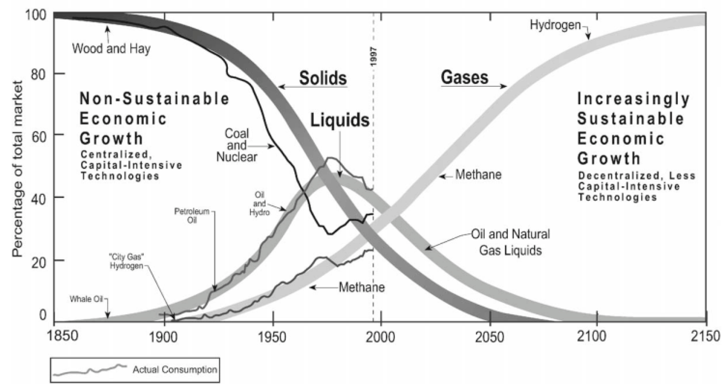
Figure 2.
Aux-GSH-sensitized TiO2 film as photoanode of PEC. Reproduced with permission from [13]. Copyright American Chemical Society, 2014.
Figure 2.
Aux-GSH-sensitized TiO2 film as photoanode of PEC. Reproduced with permission from [13]. Copyright American Chemical Society, 2014.
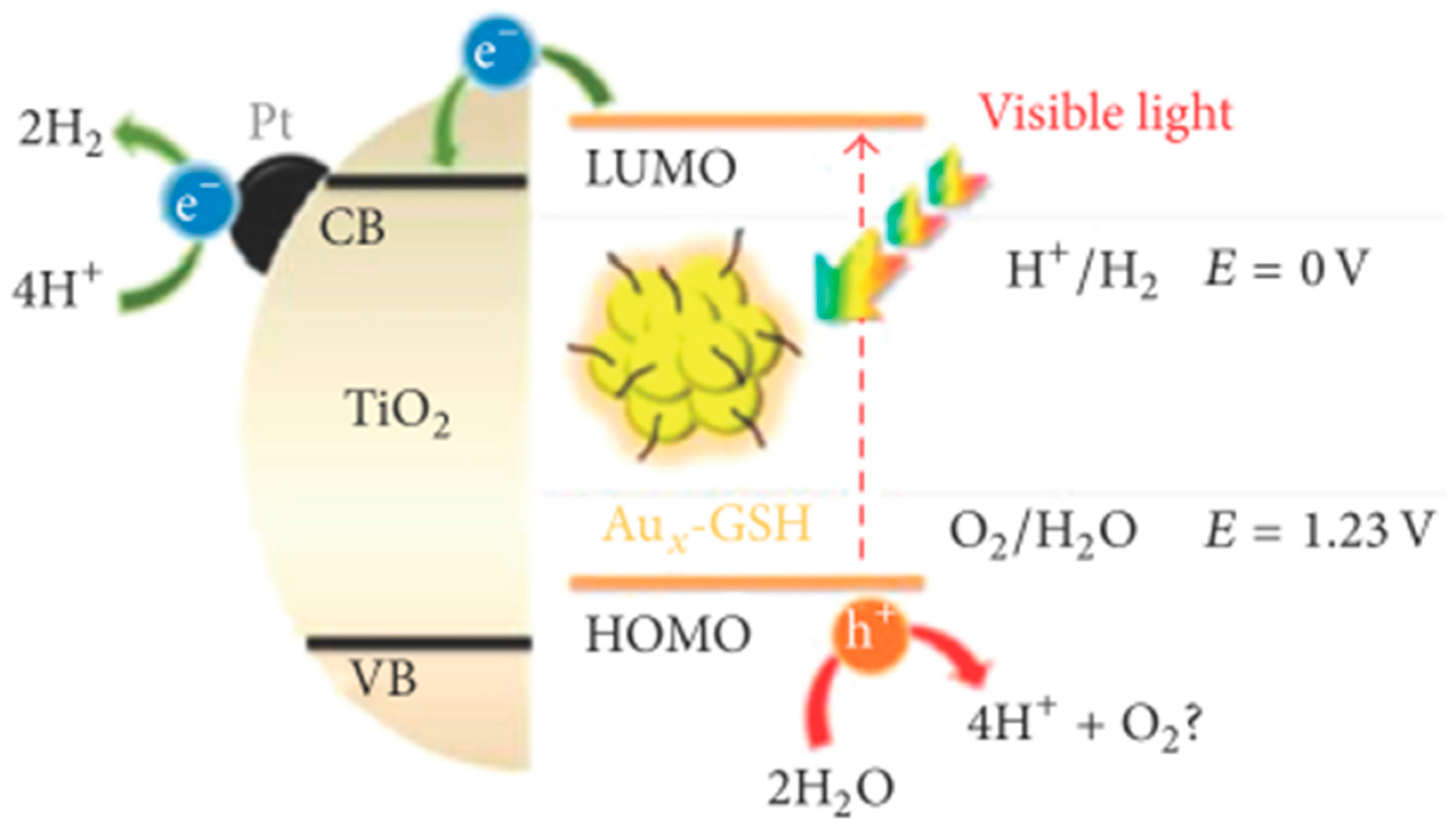
Figure 3.
Aux-GSH-sensitized Pt/TiO2 NPs photocatalytic system for water splitting reaction under visible light illumination. Reproduced with permission from [13]. Copyright American Chemical Society, 2014.
Figure 3.
Aux-GSH-sensitized Pt/TiO2 NPs photocatalytic system for water splitting reaction under visible light illumination. Reproduced with permission from [13]. Copyright American Chemical Society, 2014.
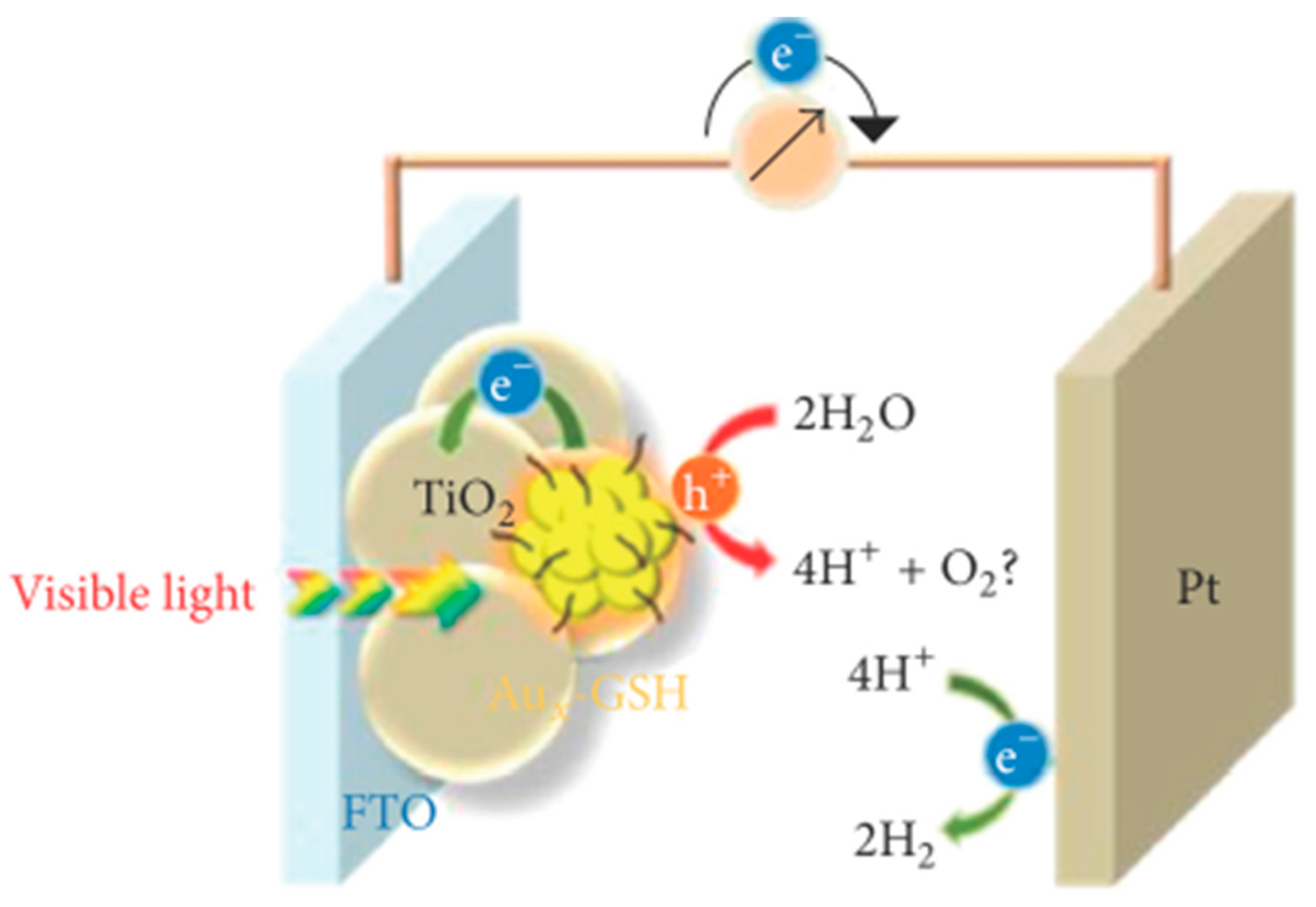
Figure 4.
Band position of different photocatalyst material in presence of aqueous electrolyte at pH = 1. Reproduced with permission from [3]. Copyright Springer, 2008.
Figure 4.
Band position of different photocatalyst material in presence of aqueous electrolyte at pH = 1. Reproduced with permission from [3]. Copyright Springer, 2008.

Figure 5.
Energy level diagram of the dye-silver bromide system. Reproduced with permission from [31]. Copyright American Chemical Society, 1965.
Figure 5.
Energy level diagram of the dye-silver bromide system. Reproduced with permission from [31]. Copyright American Chemical Society, 1965.

Figure 6.
Schematic diagram of the dye-sensitized photovoltaic cell to indicate the electron energy level in the different phases. Reproduced with permission from [32]. Copyright Nature Publishing Group, 1991.
Figure 6.
Schematic diagram of the dye-sensitized photovoltaic cell to indicate the electron energy level in the different phases. Reproduced with permission from [32]. Copyright Nature Publishing Group, 1991.
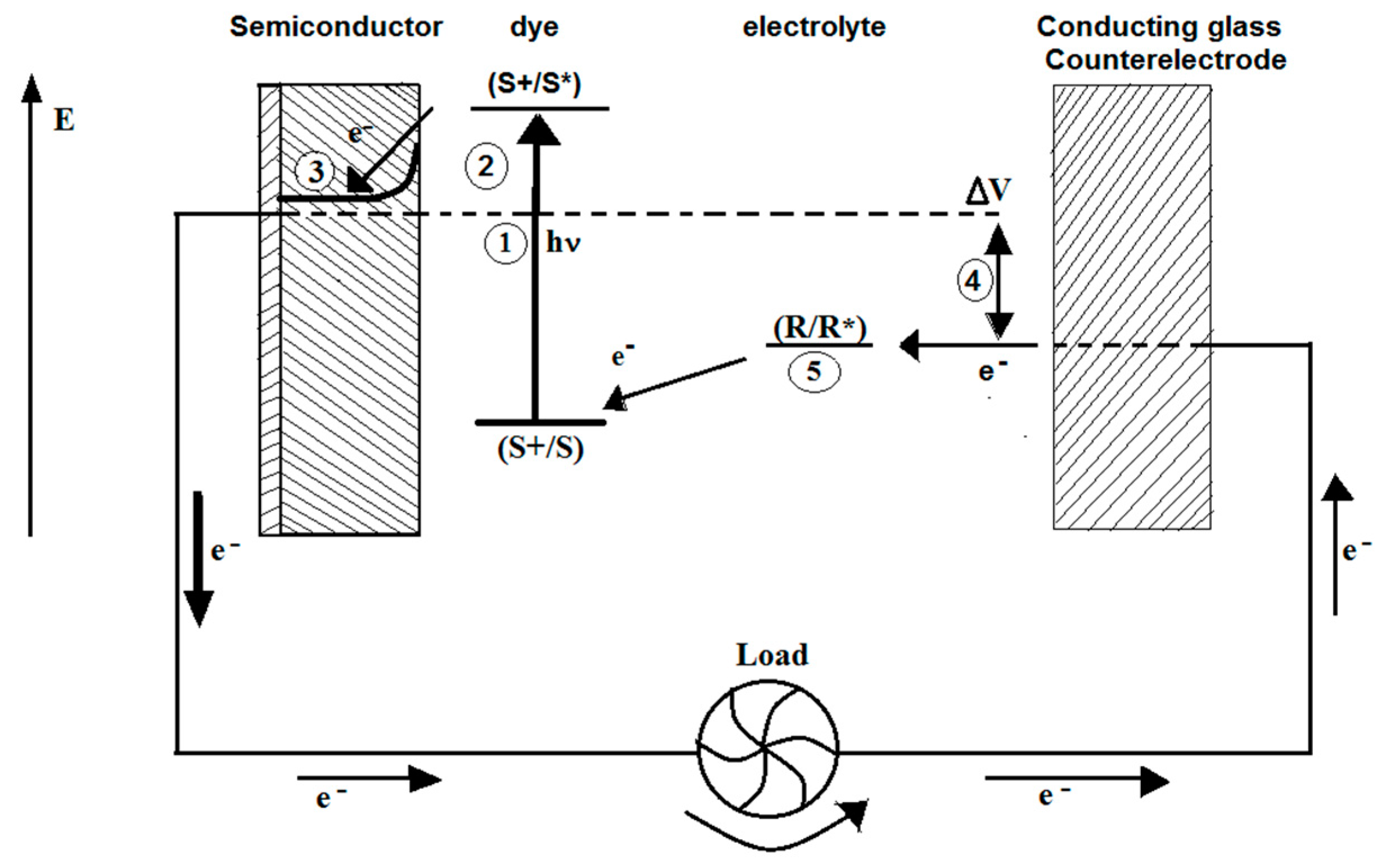
Figure 7.
Kinetic scheme for forward electron transfer and charge recombination pathway in sensitized semiconductors containing H2 and O2 evolving catalyst. Reproduced with permission from [33]. Copyright American Chemical Society, 2009.
Figure 7.
Kinetic scheme for forward electron transfer and charge recombination pathway in sensitized semiconductors containing H2 and O2 evolving catalyst. Reproduced with permission from [33]. Copyright American Chemical Society, 2009.
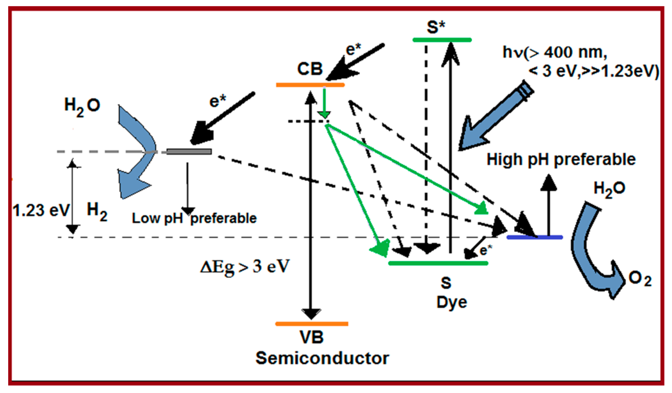
Figure 8.
Schematic diagram of linkers to bind sensitizer to metal oxide (MO). b: bridge, A: anchoring group. Reproduced with permission from [35]. Copyright Elsevier, 2004.
Figure 8.
Schematic diagram of linkers to bind sensitizer to metal oxide (MO). b: bridge, A: anchoring group. Reproduced with permission from [35]. Copyright Elsevier, 2004.
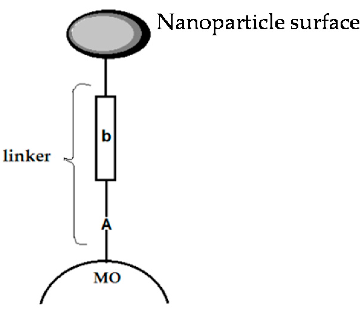
Figure 9.
Visible-light-induced water splitting using dye-adsorbed Pt/H4Nb6O17 photocatalyst in the presence of I3/I− shuttle redox mediator. Reproduced with permission from [38]. Copyright American Chemical Society, 2013.
Figure 9.
Visible-light-induced water splitting using dye-adsorbed Pt/H4Nb6O17 photocatalyst in the presence of I3/I− shuttle redox mediator. Reproduced with permission from [38]. Copyright American Chemical Society, 2013.
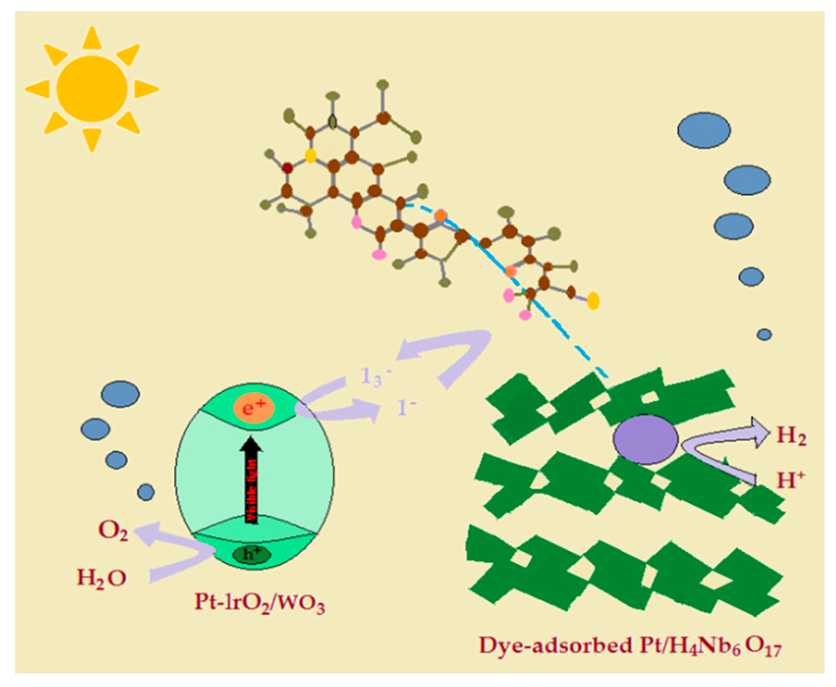
Figure 10.
Conceptual reaction scheme for declining backward reaction using nanostructured layered semiconductor. Reproduced with permission from [38]. Copyright American Chemical Society, 2013.
Figure 10.
Conceptual reaction scheme for declining backward reaction using nanostructured layered semiconductor. Reproduced with permission from [38]. Copyright American Chemical Society, 2013.
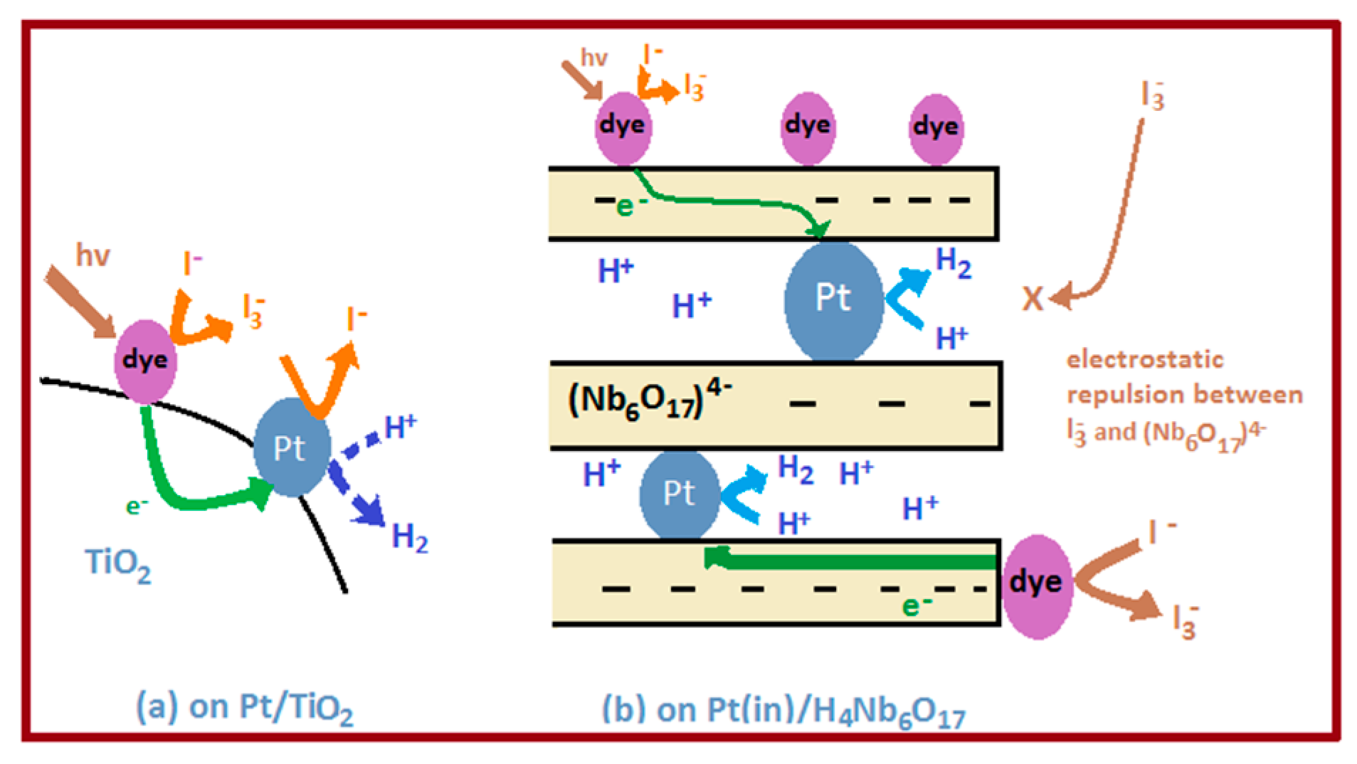
Figure 11.
Cartoon is representing an atomic layer deposition (ALD) core/shell electrode surface with ALD overlayer stabilization of a surface-bound assembly. Reproduced with permission from [40]. Copyright National Academy of Sciences, 2015.
Figure 11.
Cartoon is representing an atomic layer deposition (ALD) core/shell electrode surface with ALD overlayer stabilization of a surface-bound assembly. Reproduced with permission from [40]. Copyright National Academy of Sciences, 2015.

Figure 12.
A two-absorber Z-scheme with an 8-photon, 4-electron water splitting system. Reproduced with permission from [41]. Copyright Royal Society of Chemistry, 2012.
Figure 12.
A two-absorber Z-scheme with an 8-photon, 4-electron water splitting system. Reproduced with permission from [41]. Copyright Royal Society of Chemistry, 2012.

Figure 13.
Basic molecular structures of typical porphyrins and phthalocyanines used in dye-sensitized photocatalytic H2 production. Reproduced with permission from [63]. Copyright Royal Society of Chemistry, 2015.
Figure 13.
Basic molecular structures of typical porphyrins and phthalocyanines used in dye-sensitized photocatalytic H2 production. Reproduced with permission from [63]. Copyright Royal Society of Chemistry, 2015.

Figure 14.
Typical molecular structures of some xanthene dyes and cation-organic dyes used in dye-sensitized photocatalytic H2 production. Reproduced with permission from [63]. Copyright Royal Society of Chemistry, 2015.
Figure 14.
Typical molecular structures of some xanthene dyes and cation-organic dyes used in dye-sensitized photocatalytic H2 production. Reproduced with permission from [63]. Copyright Royal Society of Chemistry, 2015.

Figure 15.
Visible/near-IR-light-induced H2 production over g-C3N4 co-sensitized by organic dyes and the zinc phthalocyanine derivative. Reproduced with permission from [75]. Copyright American Chemical Society, 2015.
Figure 15.
Visible/near-IR-light-induced H2 production over g-C3N4 co-sensitized by organic dyes and the zinc phthalocyanine derivative. Reproduced with permission from [75]. Copyright American Chemical Society, 2015.

Figure 16.
(a) Photocatalytic H2 production rates over Zn-tri-PcNc/g-C3N4 in the presence of various electron donors under different light irradiation conditions. Conditions: 10 mg 1.0 wt % Pt-loaded catalyst with 5.0 μmol·g−1 Zn-tri-PcNc, 10 mL of water containing 50 mM AA, 10 vol % TEOA or 10 mM EDTA; (b) the relative positions of the sacrificial reagents’ redox potentials and the CB/VB (for g-C3N4), as well as the HOMO/LUMO (for Zn-tri-PcNc) levels. Reproduced with permission from [62]. Copyright American Chemical Society, 2014.
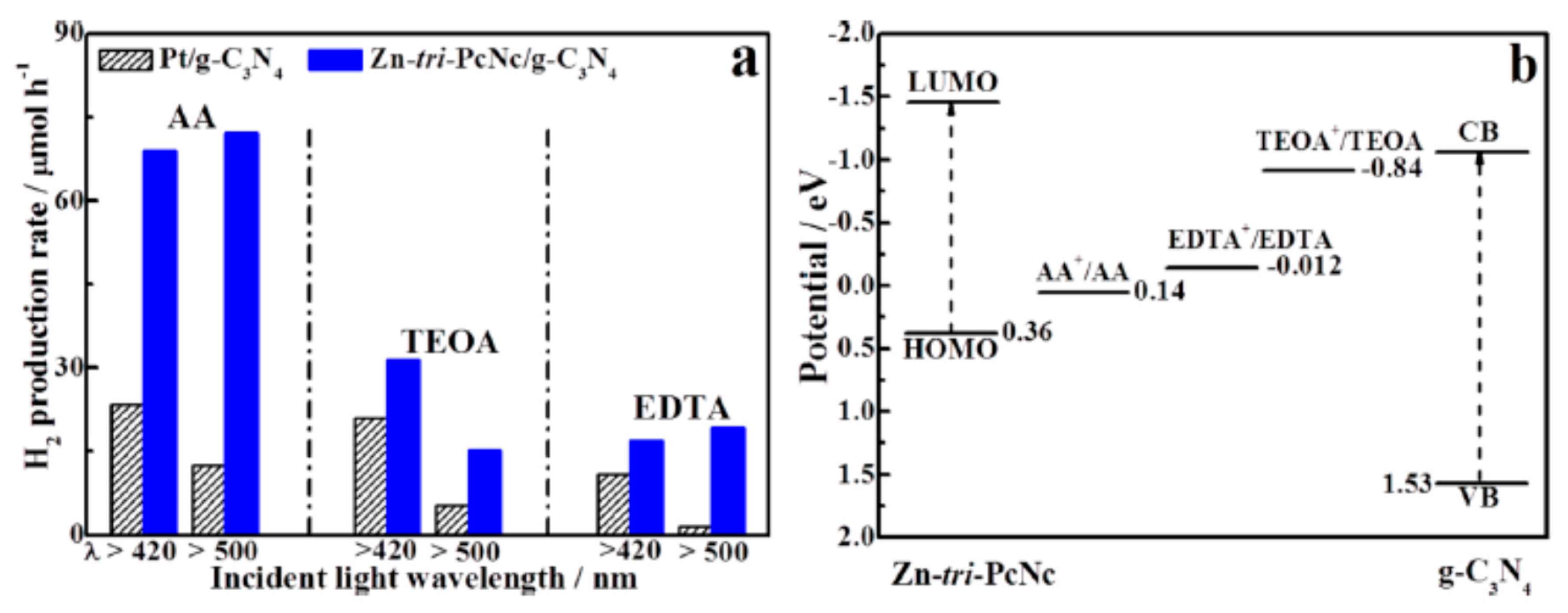
Figure 17.
PL spectra of Eosin Y/DMWCNT (a), Eosin Y/CMWCNT (b), Eosin Y/UMWCNT (c), and Eosin Y (d) in TEOA solution at pH 7. The excitation wavelength is 450 nm. Reproduced with permission from [84]. Copyright American Chemical Society, 2007.
Figure 17.
PL spectra of Eosin Y/DMWCNT (a), Eosin Y/CMWCNT (b), Eosin Y/UMWCNT (c), and Eosin Y (d) in TEOA solution at pH 7. The excitation wavelength is 450 nm. Reproduced with permission from [84]. Copyright American Chemical Society, 2007.
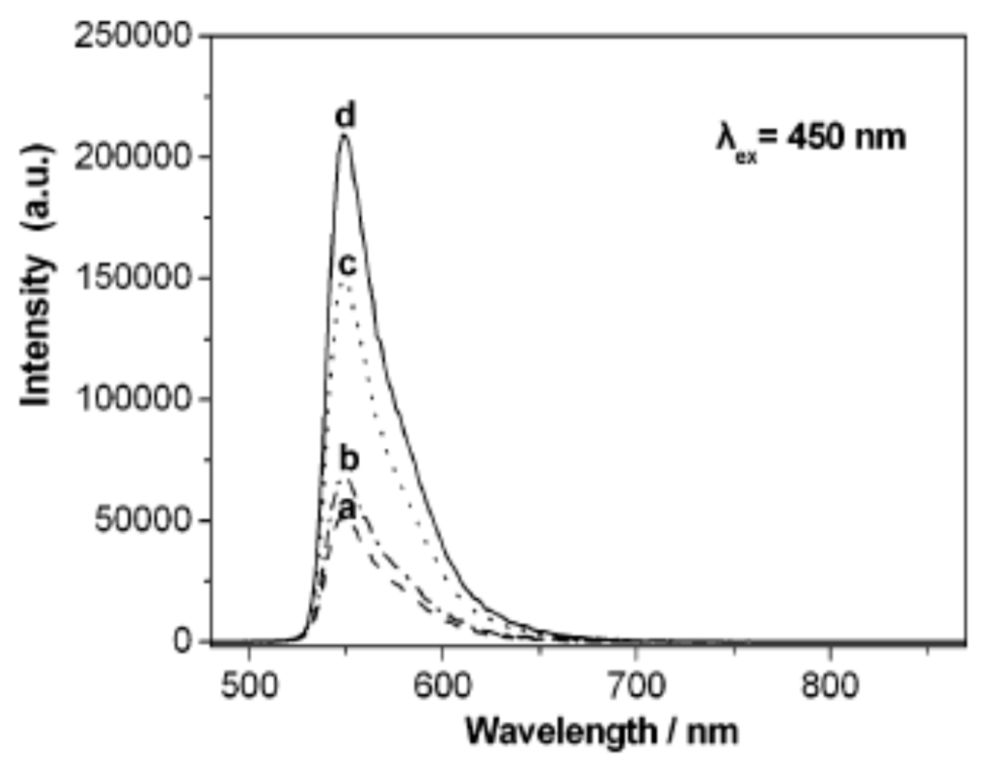
Figure 18.
The proposed photocatalytic mechanism for efficient hydrogen evolution over a dye-sensitized graphene/metal photocatalyst under visible light irradiation. Reproduced with permission from [86]. Copyright Elsevier, 2013.
Figure 18.
The proposed photocatalytic mechanism for efficient hydrogen evolution over a dye-sensitized graphene/metal photocatalyst under visible light irradiation. Reproduced with permission from [86]. Copyright Elsevier, 2013.

Figure 19.
(a) Schottky junction with energy level alignment and (b) electron transfer across the metal–semiconductor junction. Reproduced with permission from [90]. Copyright Royal Society of Chemistry, 2014.
Figure 19.
(a) Schottky junction with energy level alignment and (b) electron transfer across the metal–semiconductor junction. Reproduced with permission from [90]. Copyright Royal Society of Chemistry, 2014.

Figure 20.
Hydrogen production from CoOx, Co(OH)2, NiOx, Ni(OH)2, Fe(OH)3 and Cu(OH)2, respectively in EY solution at pH 9 for 5 h. Using 300 W Xenon arc lamp as the light source and a cut filter to eliminate the photons below 420 nm. Reproduced with permission from [95]. Copyright Elsevier, 2014.
Figure 20.
Hydrogen production from CoOx, Co(OH)2, NiOx, Ni(OH)2, Fe(OH)3 and Cu(OH)2, respectively in EY solution at pH 9 for 5 h. Using 300 W Xenon arc lamp as the light source and a cut filter to eliminate the photons below 420 nm. Reproduced with permission from [95]. Copyright Elsevier, 2014.

Figure 21.
Interaction effect plot for electron donor (TEOA), sensitizer (Eosin Y dye), platinum, and visible light irradiation time (I-time) for the percent increment in H2 generation. Reproduced with permission from [5]. Copyright Elsevier, 2011.
Figure 21.
Interaction effect plot for electron donor (TEOA), sensitizer (Eosin Y dye), platinum, and visible light irradiation time (I-time) for the percent increment in H2 generation. Reproduced with permission from [5]. Copyright Elsevier, 2011.
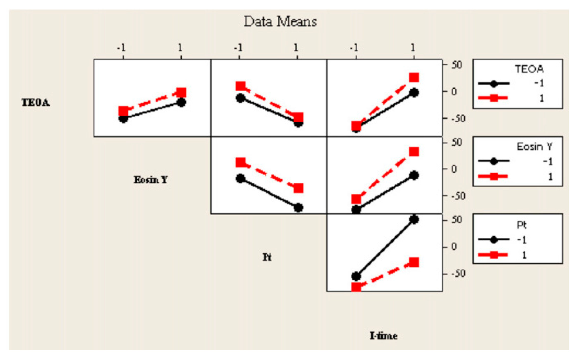
Figure 22.
Response surface and contour plot for solution pH and (NH4)2MoS4 concentration. Reproduced with permission from [100]. Copyright Elsevier, 2016.
Figure 22.
Response surface and contour plot for solution pH and (NH4)2MoS4 concentration. Reproduced with permission from [100]. Copyright Elsevier, 2016.
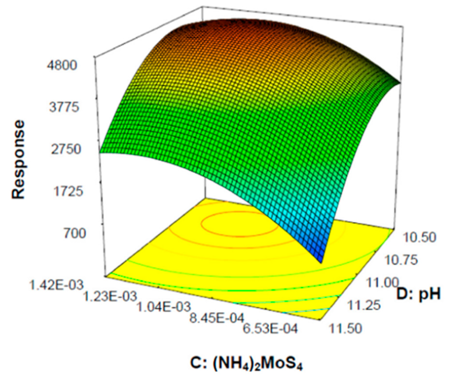
Figure 23.
A connected twin photoreactor with a modified Nafion membrane. Reproduced with permission from [112]. Copyright Elsevier, 2011.
Figure 23.
A connected twin photoreactor with a modified Nafion membrane. Reproduced with permission from [112]. Copyright Elsevier, 2011.

Figure 24.
Diagram of the H-type photoreactor for the separation of H2 and O2. Reproduced with permission from [114]. Copyright Elsevier, 2006.
Figure 24.
Diagram of the H-type photoreactor for the separation of H2 and O2. Reproduced with permission from [114]. Copyright Elsevier, 2006.

Figure 25.
Membrane-based photoreactor for the separation of H2 and O2 generated from water splitting using solar light. Reproduced with permission from [115]. Copyright American Chemical Society, 2013.
Figure 25.
Membrane-based photoreactor for the separation of H2 and O2 generated from water splitting using solar light. Reproduced with permission from [115]. Copyright American Chemical Society, 2013.
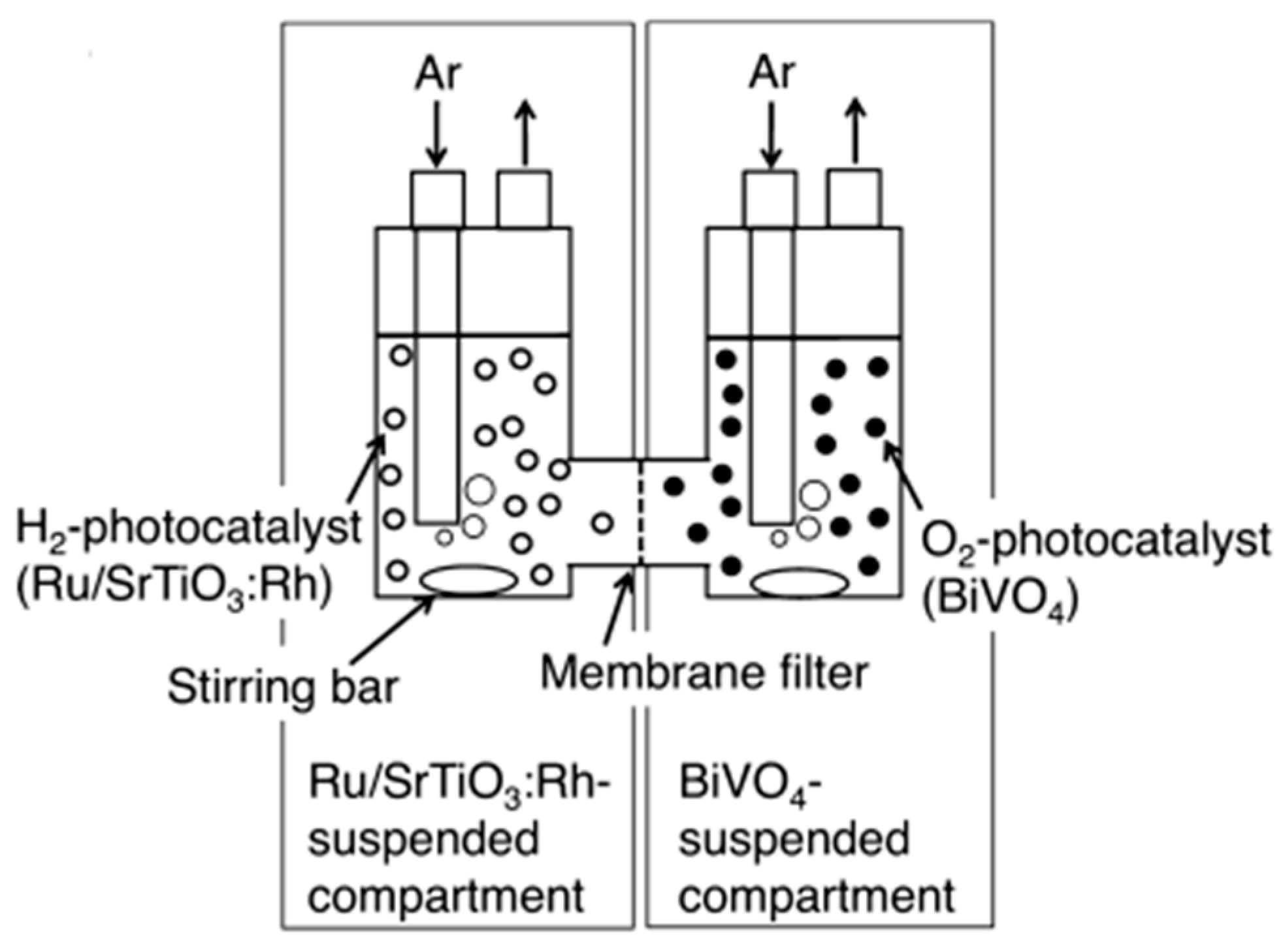
Figure 26.
Schematic diagram of a dual bed photoreactor for water splitting. Reproduced with permission from [116]. Copyright Elsevier, 2011.
Figure 26.
Schematic diagram of a dual bed photoreactor for water splitting. Reproduced with permission from [116]. Copyright Elsevier, 2011.

Figure 27.
H2 and O2 generation in a simulated dual-bed photoreactor under visible light. Reproduced with permission from [117]. Copyright Elsevier, 2009.
Figure 27.
H2 and O2 generation in a simulated dual-bed photoreactor under visible light. Reproduced with permission from [117]. Copyright Elsevier, 2009.
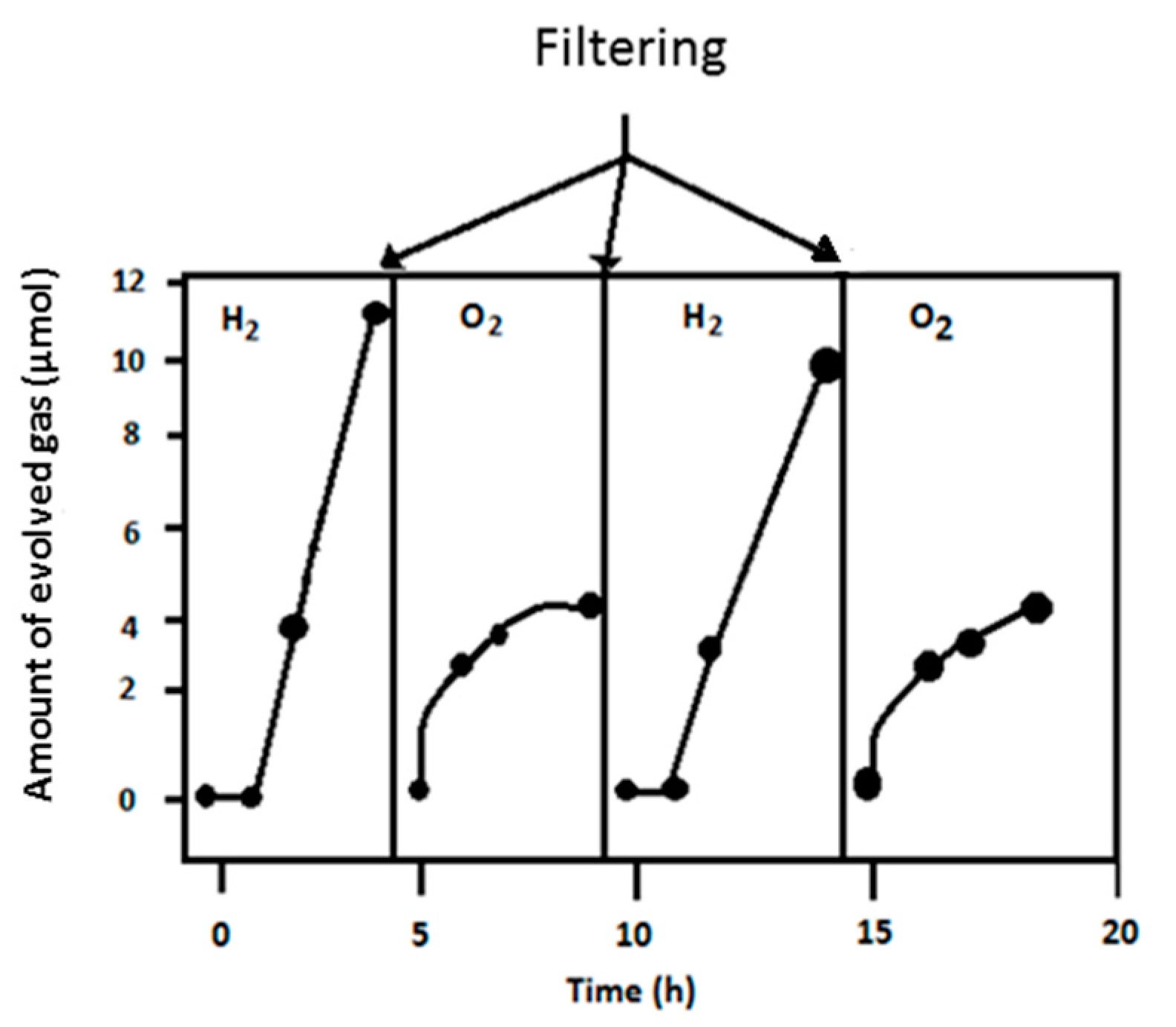
Figure 28.
Flow diagram of a three-neck-flask photoreactor with passive mixing. Reproduced with permission from [118]. Copyright Elsevier, 2011.
Figure 28.
Flow diagram of a three-neck-flask photoreactor with passive mixing. Reproduced with permission from [118]. Copyright Elsevier, 2011.

Figure 29.
Solar photocatalytic hydrogen production reactor set up. Description: (1) support; (2) storage tank; (3) gas chromatography (GC); (4) gas flow meter; (5) gas collection apparatus; (6) feeding pump; (7) circulating pump; (8) nitrogen; (9) temperature sensor; (10) pressure sensor; and (11) connecting tube. Reproduced with permission from [119]. Copyright Elsevier, 2009.

Figure 30.
CPC based direct solar photoreactor for hydrogen poduction. Reproduced with permission from [120]. Copyright Elsevier, 2010.
Figure 30.
CPC based direct solar photoreactor for hydrogen poduction. Reproduced with permission from [120]. Copyright Elsevier, 2010.
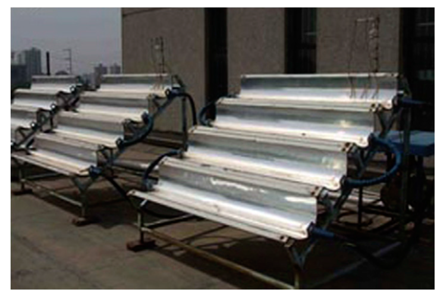
Figure 31.
Pilot plant scale hybrid photoreactor for continuous operation, artificial illumination, and natural sunlight. Reproduced with permission from [122]. Copyright Elsevier, 2012
Figure 31.
Pilot plant scale hybrid photoreactor for continuous operation, artificial illumination, and natural sunlight. Reproduced with permission from [122]. Copyright Elsevier, 2012


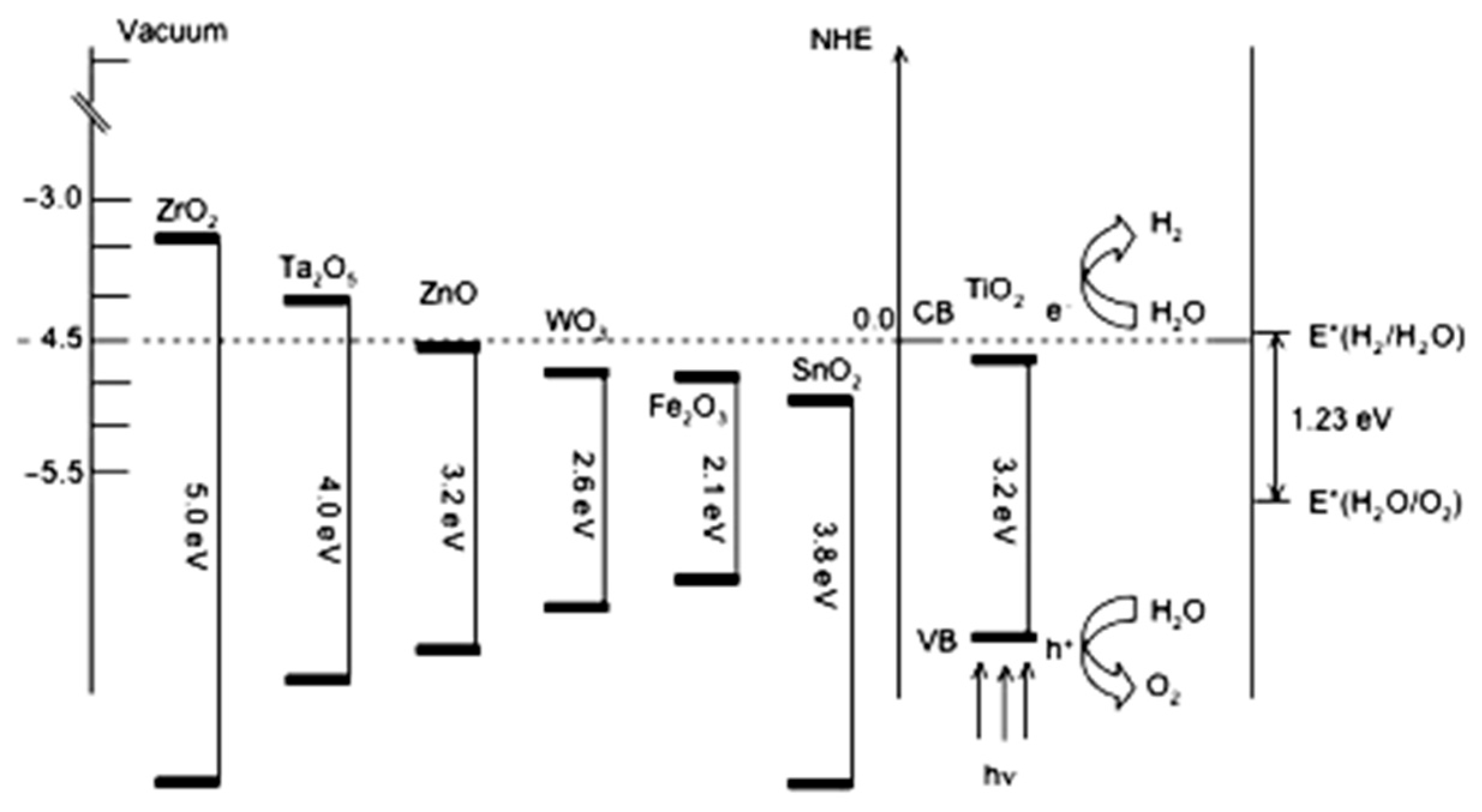
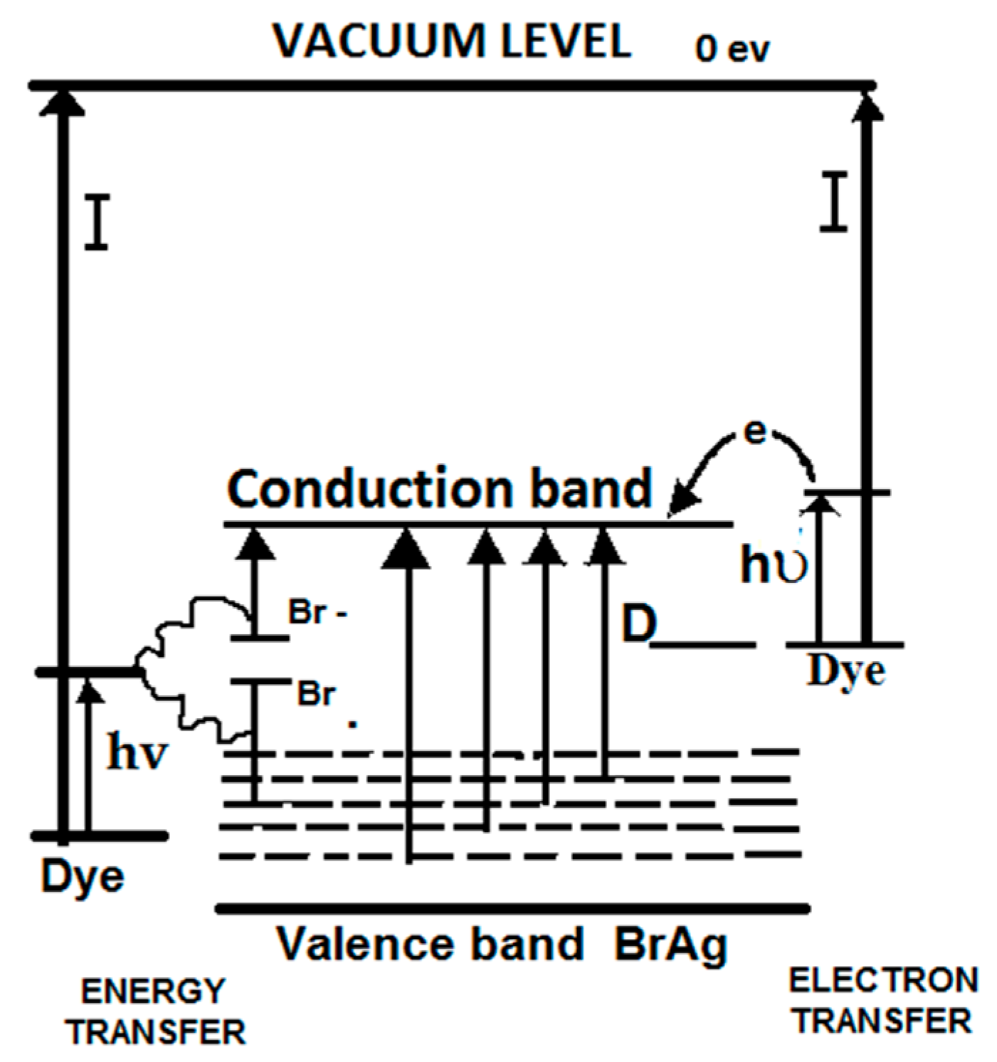
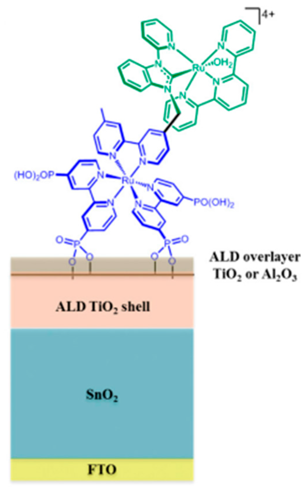
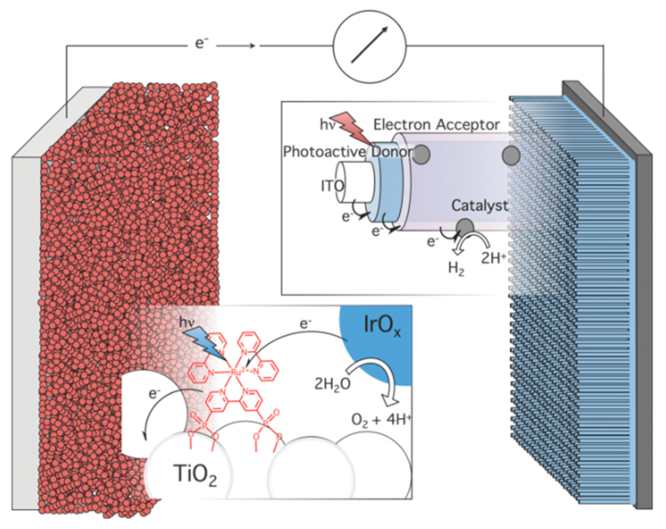
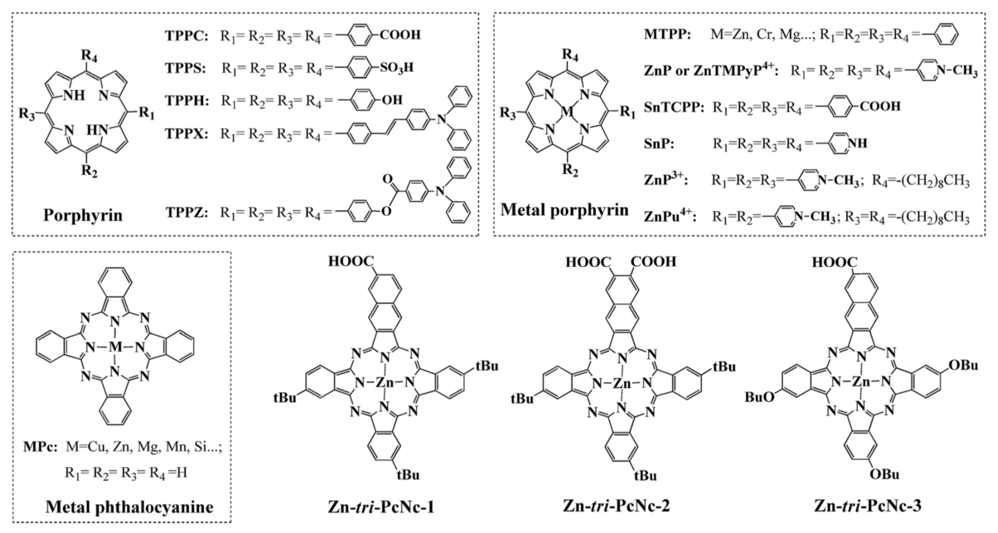
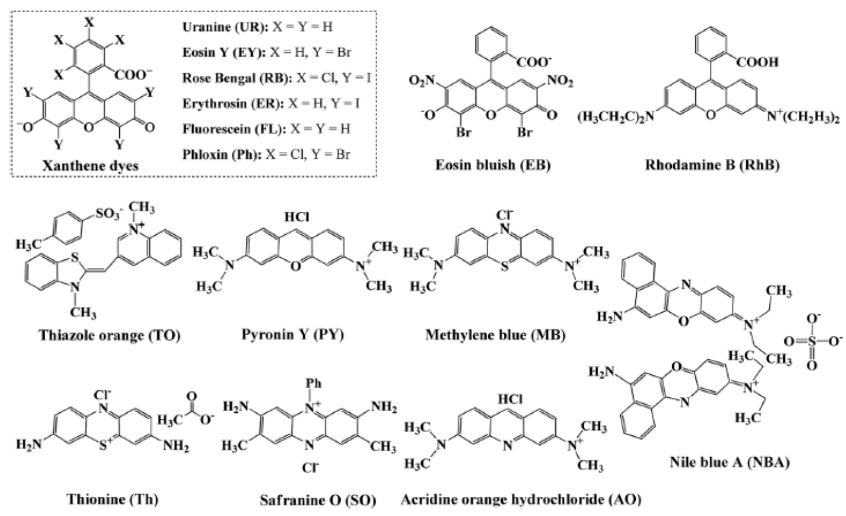
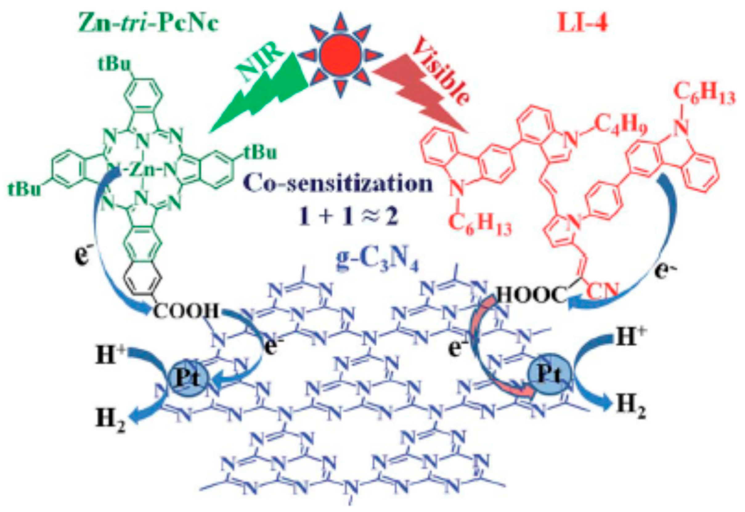
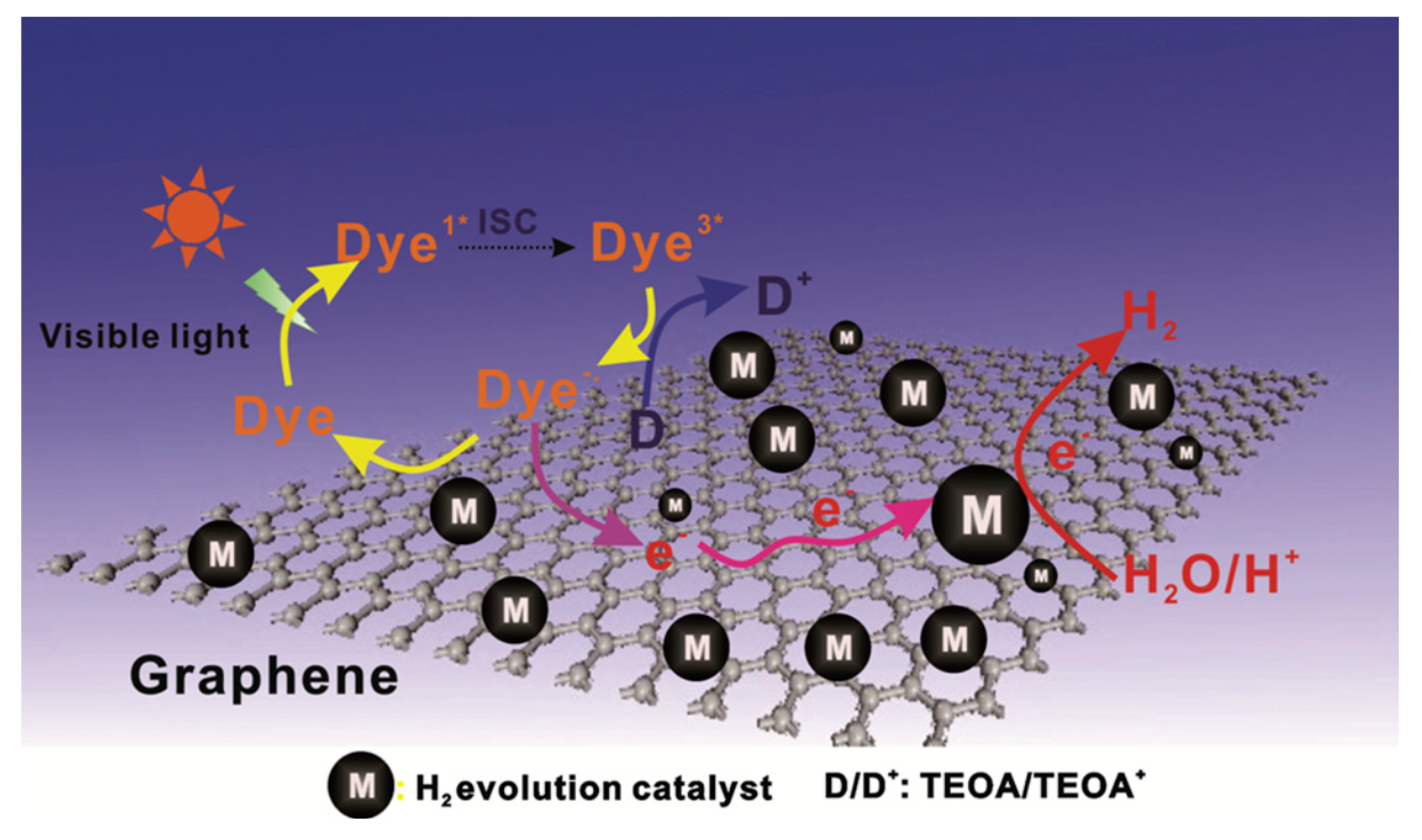
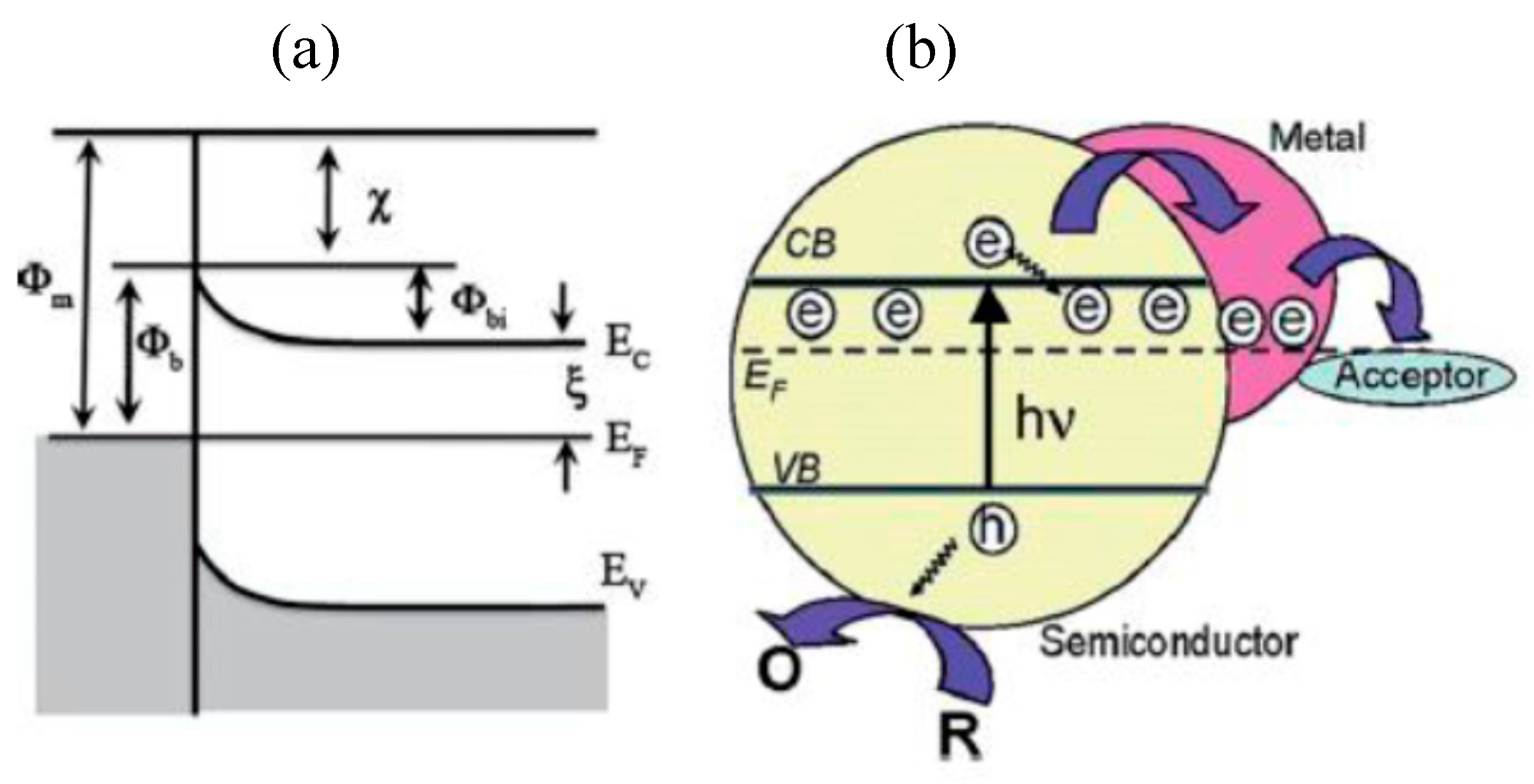
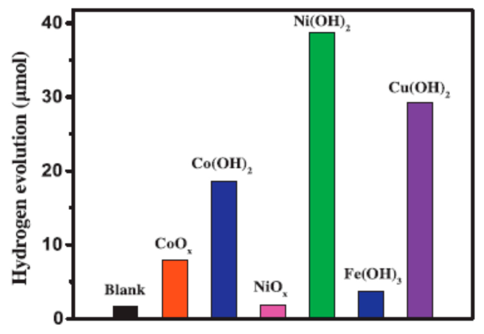
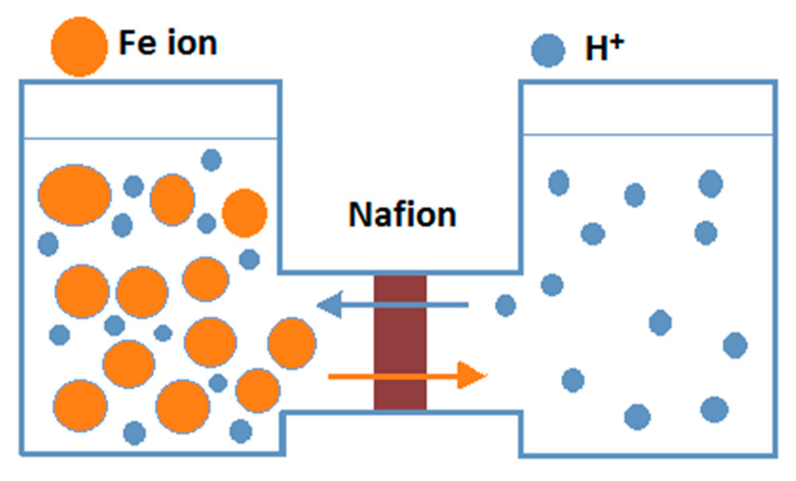
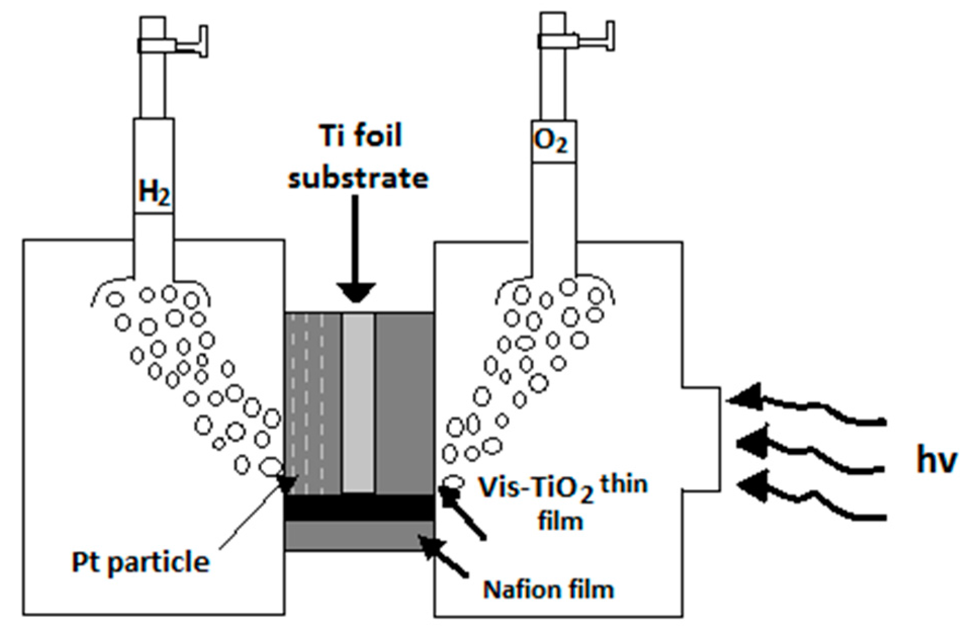
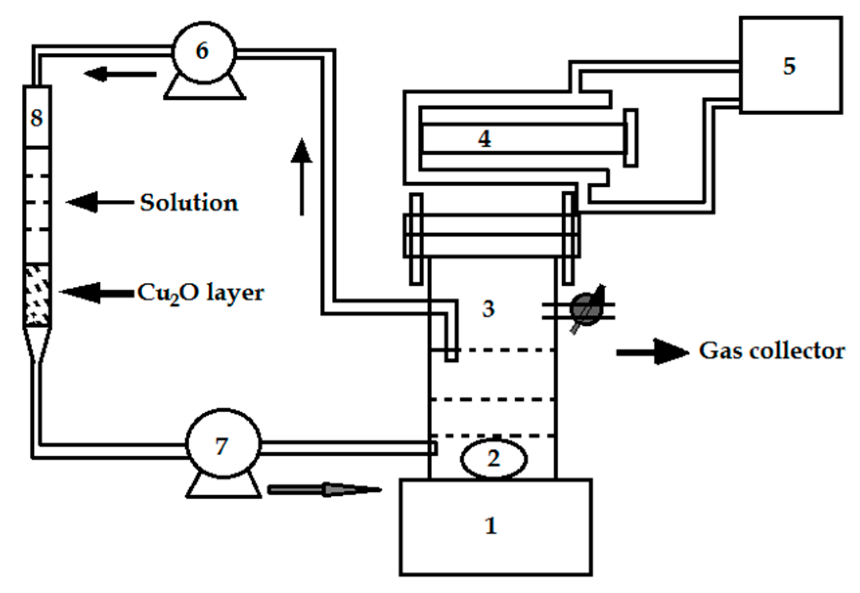
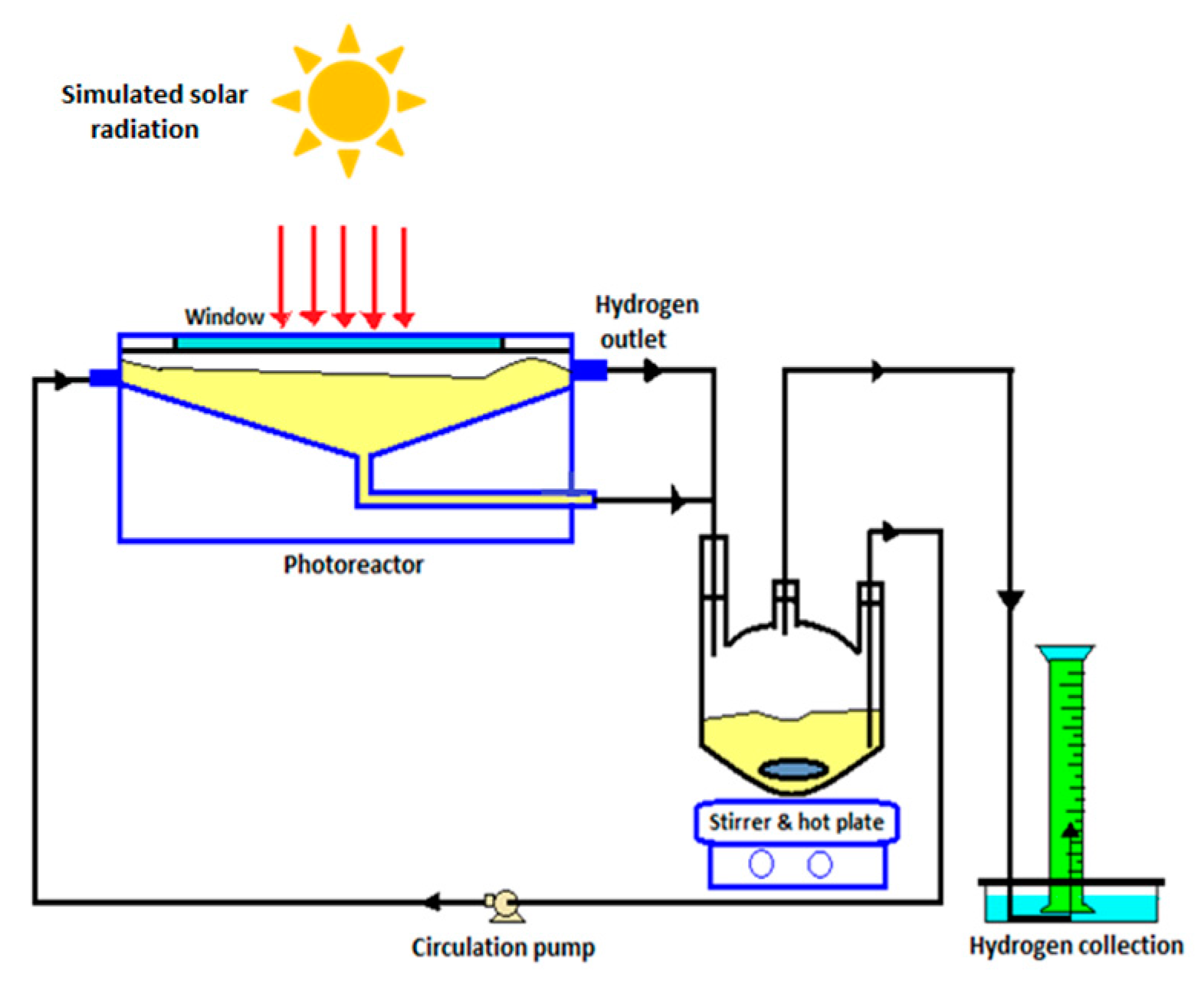
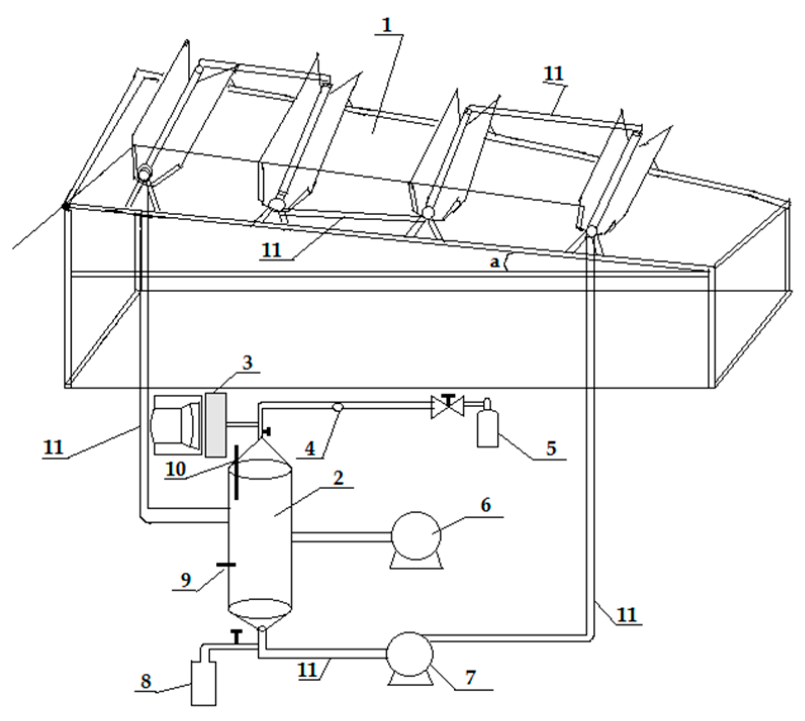
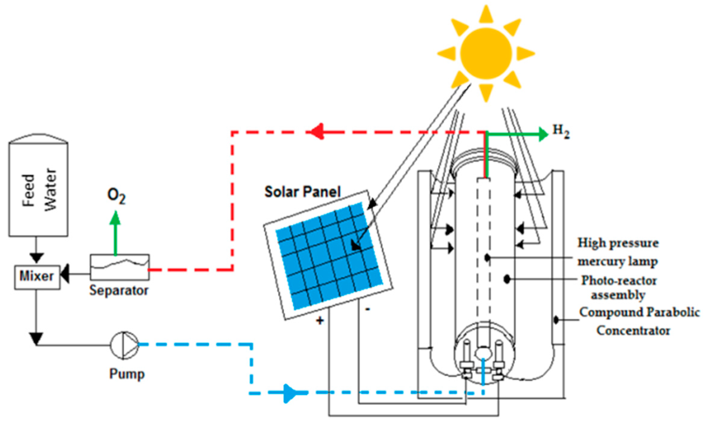
Table 1.
Modification of photocatalyst materials for visible light activity.
| No. | Photocatalyst Modification Technique | Mechanism of the Process | Advantage/Disadvantage | Results/Comments | References |
|---|---|---|---|---|---|
| 1. | Noble metal (Au, Ag, Cu, Pt, Ru, etc.) loading | Fermi levels of the noble metals are less than the semiconductor, and thus the conduction band electron transfer occurs more easily to the metal particles deposited on the surface of the semiconductor | (i) suppress the e−/h+ recombination (ii) help electron transfer in water-splitting (iii) noble metals are expensive (iv) much higher metal deposition results lower efficiency | platinum and gold loading is beneficial than palladium loading due to their opposite work function and electron affinity | [17,18,19,20,21] |
| 2. | Doping with transition metal ions such as Cr, Co, Ni, Mn, and Fe | Upon incorporation of metal ion into semiconductor photocatalyst, an impurity energy level is formed in the band gap of semiconductor | (i) doping with transition metal ions expand the photo-response of semiconductor photocatalyst into the visible region (ii) deep doping create recombination centers | Metal ions doped near the semiconductor photocatalyst surface for efficient charge transfer | [17,22] |
| 3. | Doping with anions such as C, P, S, N, O, and F | Upon doping band gap narrowing occurs in the semiconductor photocatalyst | (i) doping with anions in TiO2 shift its photo-response to the visible region (ii) anions hardly form any recombination centers like cations | TiO2 band gap narrow down occurs due to the overlapping of 2p orbitals of O with p orbitals of N | [17,23] |
| 4. | Composite semiconductor; small band gap CdS (2.4 eV) and large band gap semiconductors such as TiO2 (3.2 eV), SnO2 (3.5 eV) | A large band gap semiconductor is attached to a small band gap semiconductor; conduction band electrons are injected from the small band gap semiconductor to the large band gap semiconductor | (i) combination of small and large band gap semiconductors provide improved photocatalytic performance due to adequate charge separation | CdS–SnO2 system produces hydrogen under visible light irradiation in the presence of EDTA; CdS–TiO2 system produces hydrogen under visible light in the presence of Na2S. | [17,24,25] |
| 5. | Valence band controlled photocatalyst | Metals such as bismuth (6s orbital), tin (5s orbital) and silver (4d orbital) contribute to the formation of valence band of these photocatalysts above the 2p orbital of oxygen | (i) this process makes the photocatalysts visible light active | BiVO4 and AgNbO3 are suitable for O2 evolution, and Pt/SnNb2O6 is suitable for H2 evolution | [17,26,27,28] |
| 6. | Metal ion implantation | In this method, high energy ions are injected into the semiconductor which modifies the electronic structure | (i) overlapping of the d-orbital of Titanium with implant metal d-orbital occurs and that leads to a reduction of the band gap | Metal ion implantation is very efficient for red shift, and no electron mediator is required | [17] |
| 7. | Dye-sensitization | Upon visible light illumination, the excited dye molecule introduce electron into the conduction band of semiconductor to begin the photocatalytic reaction; the conduction band electron is transmitted to noble metal at the semiconductor surface to undertake water reduction | (i) hydrogen generation rate is improved by dye absorption onto photocatalyst surface (ii) careful design of dye and semiconductor couple is necessary to prevent charge trapping and recombination which lowers the efficiency of the dye-sensitized semiconductor | Transition metal-based dyes are the best dyes regarding intense charge transfer in the visible spectral range | [8,17] |
Table 2.
Dye-sensitized overall water splitting under visible light: photocatalytic and photoelectrochemical processes.
Table 2.
Dye-sensitized overall water splitting under visible light: photocatalytic and photoelectrochemical processes.
| No. | Process Details | Light Source and Accessories | Other Experimental Details | Results/Comments | References |
|---|---|---|---|---|---|
| 1. | Photocatalytic water splitting on organic dye-sensitized KTa(Zr)O3 photocatalyst | Xenon lamp (300 or 500 W) | A total of 17 sensitizers (dye) were used to modify the photocatalytic activity of PtO x/KTa(Zr)O3 for water splitting | Modification with cyanocobalamin (B12) was the most promising with energy conversion efficiency of about 0.013% | [43] |
| 2. | Ruthenium polypyridyl-sensitized solar cells for water splitting in the presence of a biometric electron transfer mediator; | Filtered white light illumination (λ = 450 nm light) at 4.5 mW·cm−2 intensity | Iridium oxide nanoparticles are bonded to benzimidazole-phenol mediator and 2-carboxyethylphosphonic acid anchoring molecule | QY (2.3%) is more than doubled with the use of an electron transfer mediator | [42] |
| 3. | Heteroleptic ruthenium dye-sensitized photoelectrochemical cell for water splitting | 450 nm light at 7.8 mW·cm−2 | Modified ruthenium dye adsorbed on IrO2·nH2O nanoparticles in aqueous solution (1 M) of Na2S2O8; this system undergoes rapid electron transfer into anatase TiO2 | QY of approximately 0.9% | [33] |
| 4. | Water splitting from bipolar Pt/dye-sensitized TiO2 photoanode arrays | Xenon lamp (2500 W) with IR filter, light intensity 100 mW·cm−2 | Anode: Ru-dye Z-907 coated TiO2, Electrolyte: iodide/iodine, Cathode: Pt | QY 3.7% | [44] |
| 5. | Water splitting in a photoelectrochemical device with a molecular Ru catalyst assembled on dye-sensitized nano-TiO2 | Xenon lamp (500 W) with 400 nm cut-off filter | Sensitizer: [Ru(bpy)2(4,4′-(PO3H2)2bpy)]2+; Nafion membrane was used to immobilize the hydrophobic catalyst; Pt cathode | Strong acidic pH of commercial Nafion membrane led to a fast decay of the photocurrent | [45] |
| 6. | Organic dye-sensitized Tandem photoelectrochemical cell for water splitting | White LED light (λ > 400 nm), light intensity 100 mW·cm−2 | Photocathode: organic dye P1 as photo absorber and a complex molecular Co1 as H2 generation catalyst on nano-NiO; Photoanode: organic dye L0 as photosensitizer and a molecular complex Ru1 as O2 generation catalyst on mesoporous TiO2 | IPCE of 25% at 380 nm under neutral condition without bias | [46] |
| 7. | Water splitting on Rhodamine-B dye-sensitized Co-doped TiO2 catalyst | Ozone-free Xenon arc lamp (300 W) with UV cut-off filter | Photocatalytic reaction was carried out in an outer irradiated Pyrex cell with Rh–B–Co/TiO2 photocatalyst powder (50 mg) dispersed in pure water (70 mL) | Dye-sensitized photocatalyst achieved stoichiometric evolution of H2 and O2 gas; the H2 generation was six times higher than sensitized photocatalyst | [39] |
© 2017 by the authors. Licensee MDPI, Basel, Switzerland. This article is an open access article distributed under the terms and conditions of the Creative Commons Attribution (CC BY) license (http://creativecommons.org/licenses/by/4.0/).
Share and Cite
MDPI and ACS Style
Chowdhury, P.; Malekshoar, G.; Ray, A.K. Dye-Sensitized Photocatalytic Water Splitting and Sacrificial Hydrogen Generation: Current Status and Future Prospects. Inorganics 2017, 5, 34. https://doi.org/10.3390/inorganics5020034
AMA Style
Chowdhury P, Malekshoar G, Ray AK. Dye-Sensitized Photocatalytic Water Splitting and Sacrificial Hydrogen Generation: Current Status and Future Prospects. Inorganics. 2017; 5(2):34. https://doi.org/10.3390/inorganics5020034
Chicago/Turabian StyleChowdhury, Pankaj, Ghodsieh Malekshoar, and Ajay K. Ray. 2017. "Dye-Sensitized Photocatalytic Water Splitting and Sacrificial Hydrogen Generation: Current Status and Future Prospects" Inorganics 5, no. 2: 34. https://doi.org/10.3390/inorganics5020034
Note that from the first issue of 2016, this journal uses article numbers instead of page numbers. See further details here.