Hydrogen Storage Stability of Nanoconfined MgH2 upon Cycling
by
 , and
, and
Priscilla Huen
1, 
Mark Paskevicius
2,
Bo Richter
1,
Dorthe B. Ravnsbæk
3 and
Torben R. Jensen
1,* 1
Center for Materials Crystallography, Interdisciplinary Nanoscience Center and Department of Chemistry, Aarhus University, Langelandsgade 140, 8000 Aarhus C, Denmark
2
Department of Physics and Astronomy, Fuels and Energy Technology Institute, Curtin University, Kent Street, Bentley, WA 6102, Australia
3
Department of Physics, Chemistry and Pharmacy, University of Southern Denmark, Campusvej 55, 5230 Odense M, Denmark
*
Author to whom correspondence should be addressed.
Inorganics 2017, 5(3), 57; https://doi.org/10.3390/inorganics5030057
Submission received: 4 July 2017
/
Revised: 18 August 2017
/
Accepted: 18 August 2017
/
Published: 23 August 2017
(This article belongs to the Special Issue Functional Materials Based on Metal Hydrides)
Abstract
:It is of utmost importance to optimise and stabilise hydrogen storage capacity during multiple cycles of hydrogen release and uptake to realise a hydrogen-based energy system. Here, the direct solvent-based synthesis of magnesium hydride, MgH2, from dibutyl magnesium, MgBu2, in four different carbon aerogels with different porosities, i.e., pore sizes, 15 < Davg < 26 nm, surface area 800 < SBET < 2100 m2/g, and total pore volume, 1.3 < Vtot < 2.5 cm3/g, is investigated. Three independent infiltrations of MgBu2, each with three individual hydrogenations, are conducted for each scaffold. The volumetric and gravimetric loading of MgH2 is in the range 17 to 20 vol % and 24 to 40 wt %, which is only slightly larger as compared to the first infiltration assigned to the large difference in molar volume of MgH2 and MgBu2. Despite the rigorous infiltration and sample preparation techniques, particular issues are highlighted relating to the presence of unwanted gaseous by-products, Mg/MgH2 containment within the scaffold, and the purity of the carbon aerogel scaffold. The results presented provide a research path for future researchers to improve the nanoconfinement process for hydrogen storage applications.
1. Introduction
The development of a cleaner and more sustainable energy system is urgently needed to meet our increasing energy demand, and to avoid global warming and environmental pollution due to increasing levels of carbon dioxide and other toxic gases. Hydrogen is considered a potential energy carrier, since it is an abundant, non-greenhouse gas and can be produced by the electrolysis of water [1,2,3,4]. However, gaseous hydrogen at ambient conditions has a low density of 0.082 g/L, which is a disadvantage for mobile applications, even with compression [5]. Therefore, the solid state storage of hydrogen in a metal hydride has been investigated [3,4,6,7]. Magnesium hydride, MgH2, as one of the most extensively studied hydride materials, has a moderately high theoretical gravimetric H2 density of ρm(MgH2) = 7.6 wt % H2, and a volumetric H2 density of ρv(MgH2) = 110 g H2/L [8]. However, the practical application of an MgH2-based system is hindered from the unfavourable thermodynamics and the typically slow kinetics of the hydrogen release and uptake [9,10].
To improve the hydrogen storage properties of MgH2, nanoconfinement in porous materials can be considered [11,12,13,14,15,16,17]. Preparing nanosized MgH2 from this bottom-up approach can reduce the hydrogen diffusion distance and increase the amount of hydrogen in the grain boundaries, leading to improved kinetics of hydrogenation/dehydrogenation [18]. Nanoconfinement has also been employed for other hydride materials (e.g., NaAlH4, LiBH4, and NH3BH3) and demonstrates an improvement in gas release properties [15,19,20,21,22]. Nanoconfined MgH2 in mesoporous scaffolds can be prepared through an Mg melt infiltration process followed by hydrogenation, or by a direct synthesis route using a precursor (e.g., dibutyl magnesium, MgBu2) [11,12,13,23,24,25]. The loading of MgH2 in the scaffold is between 3.6 wt % and 22.0 wt % [19].
Previous work reveals that smaller pore sizes within resorcinol-formaldehyde carbon aerogel (CA) scaffolds lead to improved hydrogen release kinetics of nanoconfined MgH2, by reducing the particle size and increasing the surface area of MgH2 [11]. However, mainly the first hydrogen release cycle has been investigated up to now. Therefore, this present study includes multiple cycles of hydrogen release and uptake. Thermal treatment of the CA scaffold in a gas flow (often CO2) can increase the surface area, up to >2000 m2/g, and the total pore volume to 2–3 mL/g, but has almost no effect on the pore size distribution. This procedure is often denoted scaffold “activation”. Therefore, CA scaffolds are considered very customisable and may possess a wide range of porosity parameters. Previous investigations of sodium aluminium hydride, NaAlH4, nanoconfined in activated scaffolds reveal that more material can be infiltrated onto an activated scaffold, i.e., there is a larger hydrogen storage capacity due to a larger pore volume, but these materials show slower kinetics for hydrogen release as compared to nonactivated scaffold [26]. Nanoconfined hydrides are mostly shown to exhibit improved kinetics of hydrogen release and uptake, but a change in thermodynamics is only observed when the scaffolds have pore sizes smaller than 2–3 nm [27].
There are a number of studies that have investigated the effect of nanoconfinement on the dehydrogenation properties of MgH2, but there is little information about the reversible hydrogen storage capacity of nanoconfined MgH2 upon cycling (hydrogen release and uptake). In addition, it has been discovered that butane gas is released (in conjunction with hydrogen) in the thermal treatment of nanoconfined MgH2, which may refer to the incomplete hydrogenation of MgBu2 after infiltration [28]. Here, we maximize the hydrogen storage capacity of nanoconfined MgH2 through multiple infiltrations and use a variety of carbon aerogel scaffolds with different pore networks. The properties of nanoconfined MgH2 samples are then compared with a focus on their hydrogen storage capacity after multiple hydrogen release and uptake cycles.
2. Results and Discussion
2.1. Porosity of the Nanoporous Scaffolds and Confinement of Magnesium Hydride
Magnesium hydride, MgH2, was nanoconfined in four different carbon aerogel scaffolds with different texture properties as shown in Table 1. The porosities of the as-synthesised scaffolds X1 and X2 are similar except for the average pore sizes, Dmax, of 16.6 ± 0.5 and 27.1 ± 2.7 nm, respectively. The surface area, SBET, and total pore volume, Vtot, of the activated scaffolds CX1 and CX2 increase significantly after heat treatment in a flow of carbon dioxide, but Dmax remains almost constant.
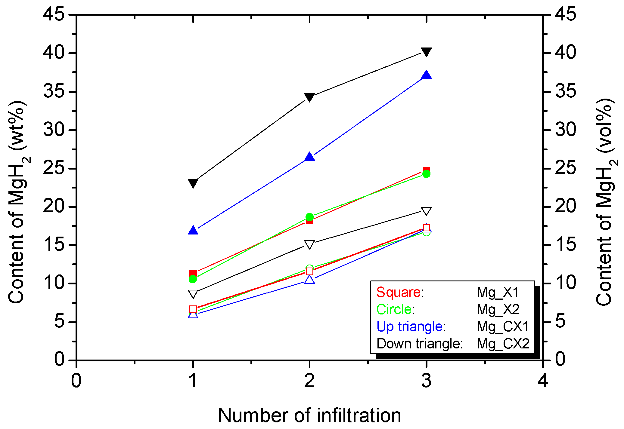
The procedures for the direct synthesis of nanoconfined magnesium hydride, MgH2 utilised in this investigation are a new modification of a previously described approach using monoliths of carbon aerogel scaffold [11,12]. The aim of this investigation is to explore new approaches to prepare high hydrogen capacity materials based on nanoconfined magnesium hydride. A total of three dibutyl magnesium infiltrations, each with three hydrogenations, were conducted in order to increase the loading of MgH2 in the porous scaffolds, with details provided in Table 1 and Table S1. The infiltrated amount of dibutyl magnesium, MgBu2, is measured gravimetrically after mechanically removing excess dibutyl magnesium that was crystallised on the surface of the scaffolds. Scaffolds X2 and CX2 show decreasing amounts of infiltrated MgBu2 for each consecutive cycle of infiltration, see Table S1, assigned to increasing amounts successfully infiltrated in each cycle. In contrast, the amount of infiltrated MgBu2 in X1 and CX1 vary more so, possibly due to difficulties in efficiently removing MgBu2 from the surface. A graphical presentation of the results from the infiltrations is presented in Figure 1. Dibutyl magnesium is assumed to be completely converted to MgH2 following the reaction Scheme (1):
Mg(C4H9)2(s) + 2H2(g) → MgH2(s) + 2C4H10(g)
The gravimetric and volumetric quantity of infiltrated magnesium hydride is calculated using the mass of scaffold, total pore volume, and bulk density of MgH2. The volumetric loading of MgH2 in the three scaffolds X1, X2, and CX1 are similar, ~17 vol %, whereas CX2 is slightly larger, ~20 vol %. However, the gravimetric hydride content varies more significantly, ~24 wt % for X1 and X2, ~37 wt % for CX1, and ~40 wt % for CX2. Recall that three independent infiltrations of MgBu2 were conducted in this work, each with three individual hydrogenations. However, this work reveals that only a moderate increase in the infiltrated amount of MgH2 is obtained after three infiltrations as compared to 12 vol % MgH2 after one infiltration in a previous work [11]. That is mainly assigned to the large difference in molar volume of MgH2 (18.2 cm3/mol) and MgBu2 (188.2 cm3/mol). As such, MgBu2 takes up a large volume after the infiltration, and only one-tenth of this volume is converted to MgH2. This is similar to the utilisation of butyllithium for the direct synthesis of nanoconfined LiH, where loadings in the range of 12–17 wt % were obtained [29]. Secondly, MgH2 may have a tendency to block the pores and stop further infiltration, which may hamper the full infiltration of the smaller pores.
2.2. Hydrogen Storage Capacity upon Cycling
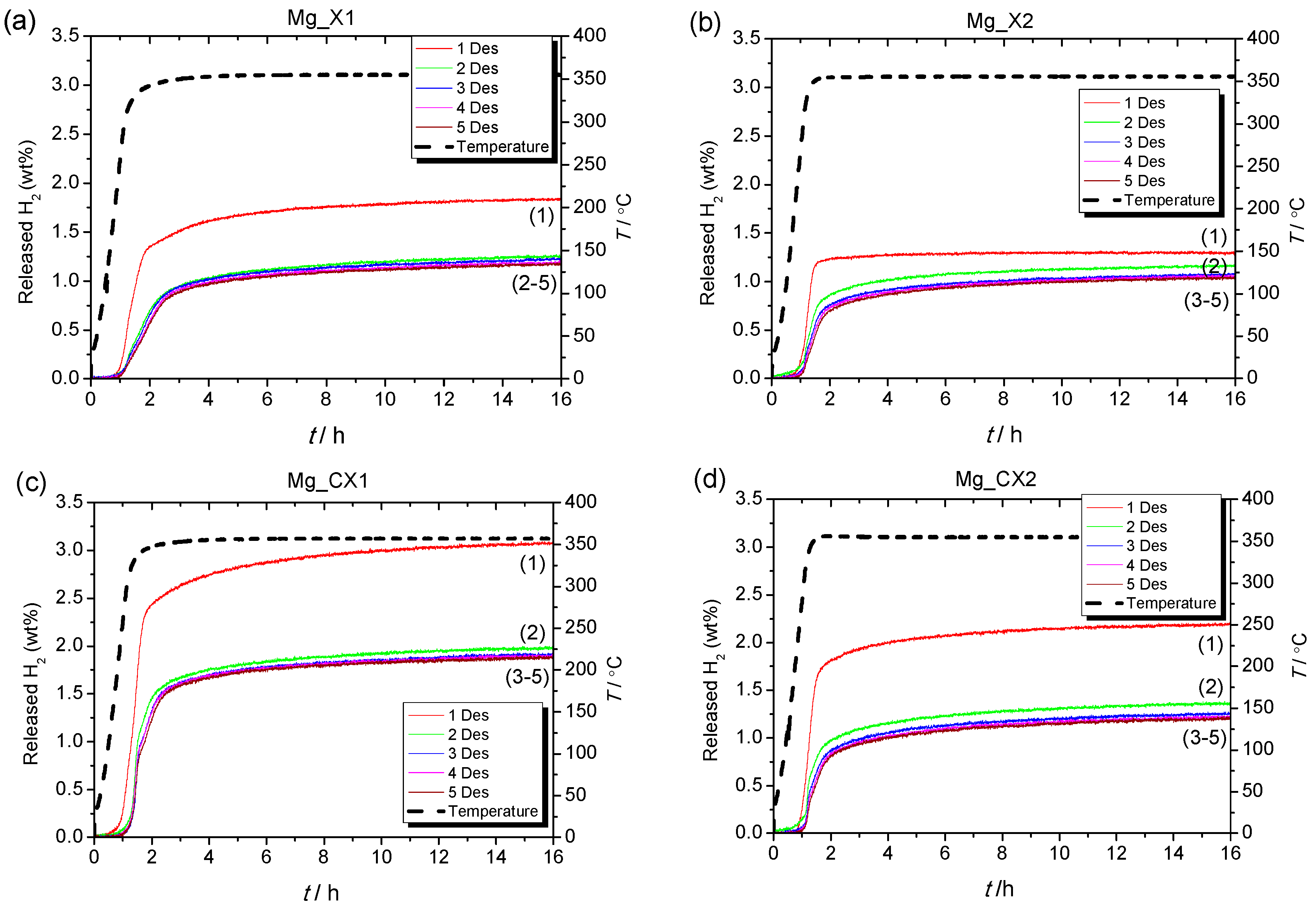
Reversible hydrogen storage properties were investigated for five cycles of hydrogen release (T = 355 °C, t = 15 h in vacuum) and uptake (T = 355 °C, t = 15 h in p(H2) = 50 bar), i.e., ∆p(H2) = 50 bar, denoted condition 1, for the four nanoconfined MgH2 samples (see Figure 2). In the first decomposition, Mg_CX1 released 3.1 wt % H2, which is slightly higher than the calculated hydrogen content of the sample based on the calculated quantity of MgH2, 2.82 wt % (see Table 2). The observed hydrogen release from Mg_X1, 1.8 wt % H2, is in accordance with the calculated value (1.88 wt % H2). Samples Mg_X2 and Mg_CX2, with larger average pore sizes, release a lower quantity of gas, 1.3 and 2.2 wt % H2, which corresponds to 68% and 71% of the calculated hydrogen content, respectively. For the following cycles, Table 2 and Figure 2 reveal a general stabilisation of the hydrogen storage capacity after the second desorption cycle.
For all four samples, the hydrogen release temperature is lower for the first cycle in comparison to further cycles. This may indicate that other reactions, besides the release of hydrogen, mainly occur in the first cycle. A thermal analysis using mass spectroscopy revealed that butane release occurs in addition to hydrogen release. This is unexpected due to the rigorous infiltration procedure, where a total of nine hydrogenation and evacuation steps are undertaken. In fact, butane is typically released at lower temperatures than hydrogen, generally in the range of 100 to 350 °C (this is further discussed later).
A similar investigation of the reversible hydrogen storage properties of the four nanoconfined samples was conducted using condition 2, i.e., the same temperature and time but a higher back-pressure for hydrogen release (p(H2) = 4–5 bar) and lower hydrogen pressure for uptake (p(H2) = 12 bar), i.e., ∆p(H2) ~7.5 bar. Figure S1 shows a dramatic difference in the hydrogen release properties in comparison to Figure 2, where hydrogen desorption was conducted under vacuum and hydrogen absorption was conducted under 50 bar.
2.2.1. Thermodynamic Considerations
Conditions 1 and 2 for hydrogen release and uptake were selected so that condition 2 was just above/below the thermodynamic equilibrium pressure for hydrogen absorption/release of Mg/MgH2 at 355 °C, i.e., peq(H2) = 6.4 bar [30], whereas condition 1 operates at a considerable “over-pressure”. The hydrogen release data is presented in Figure 2 and Figure S1, respectively, showing dramatically different hydrogen release properties. Specifically, Figure S1 displays much lower gravimetric hydrogen release (i.e., 0.4 wt % vs. 1.8 wt % for the same sample and same cycle).
For condition 2, hydrogen is absorbed at p(H2) = 11–12 bar and desorbed at p(H2) < 5.2 bar, which is well above/below the thermodynamically limiting equilibrium pressure of peq(H2) = 6.4 bar [30]. Thus, from a thermodynamic point of view, conditions 1 and 2 should provide the same hydrogen storage properties, including hydrogen capacity. The hydrogen release profiles of conditions 1 and 2 (Figure 2 and Figure S1) are similar, which suggest that hydrogen release kinetics are similar and the majority of hydrogen release is within the first 3 h in all cases. However, the amount of hydrogen release is much lower in condition 2.
The very different pressures during hydrogenation, 50 or 12 bar for conditions 1 and 2, may lead to large differences in the degree of hydrogenation for several reasons: (i) Hydrogen is known to have slow diffusion in bulk Mg and MgH2; (ii) The larger molar volume of magnesium hydride, ρmol(MgH2) = 18.15 cm3/mol as compared to magnesium ρmol(Mg) = 13.98 cm3/mol may lead to core/shell formation during the hydrogenation of magnesium particles. Thus, a magnesium hydride layer may retard further hydrogenation; (iii) The material expansion of Mg to MgH2 could lead to the blocking of the smaller pores in the scaffold, which may also retard further hydrogenation. A larger “over-pressure” as applied in condition 1 may limit the above mentioned drawbacks, (i) to (iii), and lead to complete hydrogenation of the samples.
2.2.2. Kinetics of Hydrogen Release of Nanoconfined MgH2
For all the nanoconfined magnesium hydride samples, the majority of hydrogen is desorbed during heating from room temperature to 355 °C. Furthermore, in all cases, the first H2 release profile is significantly different to the following ones, whereas the second is similar to the third, and then the H2 release profiles become almost identical. This is clearly observed in Figure 2. For all four samples, the first decomposition has faster kinetics for hydrogen release and also a lower onset temperature. The initial 10 to 50% H2 for the first cycle is released at a rate of 0.024, 0.030, 0.046, and 0.046 wt % H2/min for the samples Mg_X1, Mg_X2, Mg_CX1 and Mg_CX2, respectively. The later hydrogen release profiles, cycle no. 2 to 5, consist of two regimes, see Figure S2. Initially, the hydrogen release rate appears to increase exponentially and then linearly at higher temperatures (see Figure S2). This suggests that the hydrogen release mechanism consists of more than one process, which is also observed for Mg1−xTixH2 nanoparticles [31]. Here, we assume that the individual hydrogen release processes are independent and are due to differences in particle size, location in small or large pores or being located outside the scaffold, or consisting of Mg/MgH2/MgBu2 core–shell particles [32]. Assuming independent individual processes for hydrogen release, then the fastest process would occur at lower temperatures.
The data presented here for hydrogen release is not measured under isothermal conditions, which makes the kinetic analysis more challenging. The overall hydrogen release profile has a distorted sigmoidal shape, which cannot be modelled using Avrami-type kinetic equations, which have previously successfully been used to evaluate hydrogen release from Mg–Al–H, Mg–Cu–H, and Mg–Ni–H systems [33,34,35]. The first exponentially increasing hydrogen release does not match a power law, but the linear part of the profile can be fitted to a linear equation of the type, α(t) = b + kt, where k is assigned an apparent rate constant. Apparent kinetic data is useful to compare similar samples in a more quantitative way. The degree of hydrogen release, α(t), from the normalised hydrogen release profiles (see Figure 3) also expresses the degree of magnesium formation. For the two as-synthesised scaffolds, the linear part of the curve is approximately in the range 0.3 < α(t) < 0.6. The apparent rate constants for these two samples, Mg_X1 and Mg_X2, are k1 = 1.33(4) × 10−4 s−1 and k2 = 2.3(1) × 10−4 s−1, respectively. The carbon dioxide activated sample, Mg_CX2, is somewhat similar, 0.37 < α(t) < 0.62, with k4 = 1.65(7) × 10−4 s−1, whereas the linear hydrogen release profile occurs at a higher degree of formation, 0.50 < α(t) < 0.75, for Mg_CX1, with k3 = 1.23(2) × 10−4 s−1. The linear regime for the hydrogen release rates have onsets in the temperature range 300 to ~330 °C and in some cases continue into the isothermal heating at T = 355 °C. We note that the calculated values for the apparent rate constants have the same order of magnitude as the values for bulk- and nickel-doped magnesium hydride, i.e., 1.0 < k < 5.3 × 10⁻⁴ s−1, but at significantly higher temperatures, 370 to 390 °C [35].
The first gas release with an exponential increasing rate is assigned to MgH2 confined in the smaller pores, whereas hydrogen release at higher temperatures in the linear regime is assigned to MgH2 confined in the larger cavities or outside the scaffold. Clearly, the rate of hydrogen release is lower for the larger particles as compared to the initial hydrogen release for the smaller in all cases, despite the significantly higher temperatures in the linear regime, which is illustrated in Figure S2. Accordingly, the four samples have similar apparent rate constants. However, the hydrogen storage capacities for the nanoconfined samples presented in Table 2 are significantly lower as compared to well-known magnesium hydride–metal oxide systems, which may also show fast kinetics, e.g., MgH2–Nb2O5 [36,37]. However, this is due to a reduction of the metal and the formation of a solid solution, MgxNb1−xO [38].
2.3. Analysis of the Released Gases and Samples after Cycling
TGA-MS reveals that nanoconfined MgH2 samples release hydrogen in accordance with Sievert’s measurements (see Figure 4). However, there is also a significant quantity of butane gas that is also released, not just in the first cycle but also small but still detectable amounts on the fifth desorption cycle. However, after five desorption/absorption cycles under condition 1, the amount of butane released by Mg_X2 is about 100 times less compared to the as-prepared Mg_X2. It should again be reiterated that the sample preparation in this study was meticulous in pre-cycling a hydrogen reduction step three times in an attempt to completely transform the MgBu2 precursor, but the release gas stream is still contaminated with butane. The conversion of the MgBu2 precursor to MgH2 was conducted at T = 150 °C during sample preparation. This treatment appears more efficient for scaffolds with larger pores, which release less butane. Scaffolds with smaller pores may more effectively contain and isolate MgBu2, preventing it from hydrogenating during activation. This leads to butane release in the later hydrogenation cycles. In terms of hydrogen release, the temperature of maximum hydrogen release shifts to a higher temperature due to the particle growth of MgH2, as revealed by powder X-ray diffraction (see Section 2.4).
The minor increase in the measured mass at low temperature is caused by buoyancy. The total mass loss of the as-prepared Mg_X2 upon decomposition was 7.3 wt %, which is significantly higher than the calculated hydrogen content (1.85 wt %). Larger than expected mass loss is also observed for other samples. In addition to hydrogen and butane, other types of gas (e.g., observed as m/z ratio = 28, 36, and 38) are also released from the samples in the first decomposition (see Figure S3). The impurities may come from the organic solvent or from the scaffolds above 250 °C [11]. In the first decomposition cycles, impurities in the as-prepared samples vaporize. Thus, in further cycles, the gas stream is more pure hydrogen whilst other gases are absent and do not contribute to extra mass loss.
2.4. Comparison of As-Prepared and Cycled Nanoconfined MgH2
The four nanoconfined magnesium hydride samples were examined by powder X-ray diffraction (PXD) before and after five cycles of hydrogen release and uptake. Figure 5 reveals that the as-prepared nanoconfined sample and the five-times cycled sample Mg_CX1 contain crystalline MgH2 and MgO. Figure 5 also reveals an extreme difference in the diffraction peak width for MgH2 in the two samples. All the diffraction data was analysed quantitatively for the composition of the crystalline fraction of the sample and the average crystallite sizes using Rietveld refinement (see Table 3). In the as-prepared samples, the crystallite size of MgH2 is significantly smaller than the average pore size of the scaffold. This is due to the relatively low temperature for conversion of MgBu2 to MgH2 (150 °C), and the fact that the molar volume of MgBu2 is a factor ten larger than that of MgH2. However, only 38% to 48% of the crystalline fraction is MgH2; the major part is nanocrystalline MgO.
For sample Mg_CX2, the distribution of MgH2 and MgO is 23% and 77%, respectively. This decrease in active hydrogen storage material is in accordance with the decrease in hydrogen storage capacity measured by Sievert’s method (see Figure 2 and Figure 3). For all investigated samples, magnesium oxide is present as stable nanocrystallites (~1 nm). This can be ascribed to the fact that MgO is a much more refractory material, which does not take part in any reactions at temperatures used in the present study. The presence of oxygen is obviously a significant problem for the long term stability of nanoconfined MgH2. The primary source of oxygen appears to be the “inert” carbon aerogel scaffold. It has been found that a carbon aerogel synthesised by a variety of routes has a significant oxygen content (C–O and C=O) [39]. Typically, the oxygen content is a few percent, with much higher oxygen content reported on the surface (~10%). Magnesium is an excellent oxygen scavenger, and the results here show that it strongly reacts with the oxygen within the carbon aerogel scaffold during synthesis and hydrogen cycling at an elevated temperature.
After five cycles of hydrogen release/uptake, the Bragg peaks of MgH2 are much sharper, revealing an average crystallite size that is one order of magnitude or two orders of magnitude greater than in the as-prepared samples (Table 3). These average crystallite sizes are also much larger than the average pore sizes in the scaffolds, which demonstrates the high mobility of Mg/MgH2 during cycling (hydrogen release and uptake) at 350 °C. Thus, Mg/MgH2 tends to migrate or agglomerate in larger pore voids or outside of the scaffold. Particle growth contributes to increasing temperatures for hydrogen release due to hindered kinetics. Nanoparticles have a well-known tendency to grow to larger particles. Previous work demonstrates that sodium alanate, NaAlH4, prefers to crystallise in the larger pores in CA scaffolds [26], and may also migrate out of the scaffold upon cycling [40].
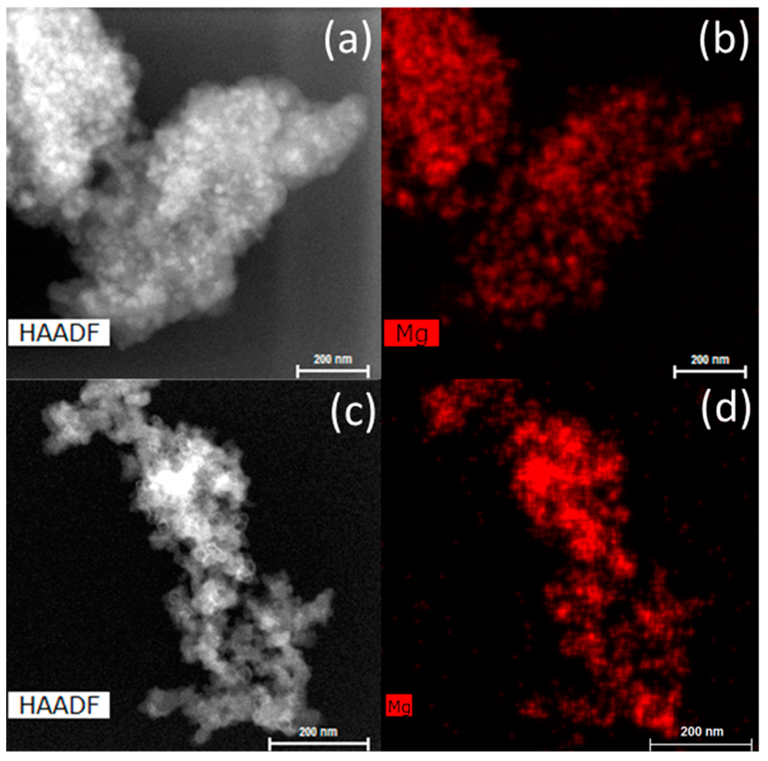
The infiltrated scaffolds, before and after hydrogen cycling, were investigated by transmission electron microscopy (TEM) (see Figure 6). After infiltration, the MgH2 is well-dispersed in the carbon scaffold (<25 nm). After five desorption/absorption cycles, MgH2 particles appear to form larger agglomerations (~100 nm). However, it is difficult to determine if the agglomerates of MgH2 are still within the scaffold or on the surface from the TEM data given that it is a transmission-based technique. Given the average carbon aerogel pore size of 25 nm, it seems likely that Mg/MgH2 has migrated to the surface of the scaffold outside of the pore network.
3. Materials and Methods
3.1. Synthesis of Carbon Scaffolds
Two batches (denoted X1 and X2) of resorcinol-formaldehyde carbon aerogel were synthesized as described previously [11,41]. Resorcinol (41.3 g, Sigma-Aldrich, Brøndby, Denmark, ≥99.0%) and formaldehyde (56.9 mL, 37 wt % in H2O, stabilized by 10–15% methanol, Sigma-Aldrich) were added to deionized water (56.6 mL) under stirring. Sodium carbonate, Na2CO3 (65 mg, Sigma-Aldrich, 99.999%) was added to the synthesis of X1 (pH = 6.47) and 40 mg to that of X2 (pH = 6.20). The mixtures were kept in sealed containers at room temperature for 24 h, then at 50 °C for 24 h, and finally at 90 °C for 72 h. The depth of the solution in the sealed containers was less than 0.5 cm to ensure the homogeneity of the carbon aerogel. After cooling, the solid gels were immersed in an acetone bath to exchange all the water inside the pores. The solid gels were then cut into small pieces with average dimension 1 cm × 0.5 cm × 0.4 cm and pyrolysed at 800 °C (ΔT/Δt = 3 °C/min) in N2 for 6 h. A portion of both samples X1 and X2 underwent further heat treatment from room temperature (RT) to 950 °C (ΔT/Δt = 6 °C/min) followed by an isothermal step at 950 °C for 5 h in a constant CO2 flow in order to increase the surface area (SBET) and total pore volume (Vtot) [42]. These samples are denoted CX1 and CX2. The average dimension of the monoliths decreased significantly to only 10–20% of their initial volume. All the synthesized carbon aerogels were degassed in vacuum at 350 °C for several hours and stored inside an argon-filled glovebox.
3.2. Direct Synthesis of Nanoconfined Magnesium Hydride
Monoliths of carbon aerogel with an average volume of 0.2 cm3 were immersed in 1 M di-n-butylmagnesium, Mg(CH2CH2CH2CH3)2, denoted MgBu2 (~5 mL, in ether and hexanes, Sigma-Aldrich) for two days. The solvent was removed using Schlenk techniques and the monoliths were dried for several hours in an inert argon atmosphere. Excess white MgBu2 on the surface of the black scaffold was removed mechanically. The amount of infiltrated dibutyl magnesium was determined from the weight gain of the monoliths before and after each infiltration. Afterwards, the infiltrated monoliths were placed in an autoclave (Swagelok, Esbjerg, Denmark) and heated to 150 °C (ΔT/Δt = 5 °C/min) under p(H2) = 100 bar and kept at 150 °C for 1 h to convert MgBu2 to MgH2 and butane. The autoclave was then evacuated and kept in dynamic vacuum for 30 min to remove the released butane gas. The hydrogenation and evacuation procedures were repeated two further times at 150 °C to ensure a high conversion of MgBu2 to MgH2. Finally, the samples were cooled to room temperature under hydrogen pressure. These MgBu2 infiltration and consequent hydrogenation procedures were repeated three times (3×) for each of the four monolithic samples, and finally the prepared samples were hand ground into powder for further characterisation. The infiltrated volumetric quantity of hydrogen storage material, MgH2, is calculated from the weight gain of the scaffold and the bulk densities ρ(MgH2) = 1.45 g/cm3 and ρ(MgBu2) = 0.736 g/cm3. Table S1 provide details about the amounts of MgBu2 infiltrated in each procedure and the total amounts of magnesium hydride in each scaffold. The magnesium hydride-containing scaffolds are denoted Mg_X1, Mg_X2, etc. The samples were stored and handled inside an argon-filled glovebox with H2O/O2 levels below 1 ppm.
3.3. Characterisation
The porosity analysis was performed using a Nova 2200e surface area and pore size analyser (Quantachrome Instruments, Odelzhausen, Germany). The properties of the carbon aerogels were deduced from N2 adsorption/desorption measurements at 77 K. The surface area (SBET) was measured using the Brunauer–Emmett–Teller (BET) method, and the micropore volume (Vmicro) was determined by the t-plot method [43,44]. The average pore size (Dmax) and mesopore volume (Vmeso) were recorded by the Barrett–Joyner–Halenda (BJH) method during desorption [45]. The total pore volume (Vtot) of the scaffold was obtained from the point at maximum p/p0 ~1.
The thermal properties of nanoconfined MgH2 before and after the desorption/absorption cycles were studied by thermogravimetric analysis (TGA) coupled with mass spectroscopy (MS). TGA was carried out using a STA 6000 (Perkin Elmer, Skovlunde, Denmark), and the evolved gases were detected by a HPR-20 QMS Mass Spectrometer (Hiden Analytical, Warrington, UK). A few milligrams of sample was placed in an aluminium crucible and heated (ΔT/Δt = 5 °C/min) in an argon flow of 40 mL/min.
The stability of the hydrogen storage capacity of nanoconfined MgH2 samples was investigated over five cycles of hydrogen release and uptake by Sievert’s measurements using an in-house custom apparatus [30]. Approximately 100 mg of sample was sealed in an autoclave and studied for five desorption and absorption cycles under two different conditions. For condition 1, the samples were heated in vacuum from room temperature to 355 °C (ΔT/Δt = 5 °C/min) and kept isothermal for 15 h during hydrogen release. Then, hydrogen absorption was conducted at p(H2) = 50 bar for 15 h at 355 °C, i.e., ∆p(H2) = 50 bar. The sample was then cooled to room temperature under the same hydrogen pressure. For condition 2, the samples were heated to 355 °C (ΔT/Δt = 5 °C/min) and kept at 355 °C for five cycles. Hydrogen release was conducted at p(H2) = 4–5 bar for 15 h at 355 °C and hydrogen absorption at p(H2) = 12 bar for 15 h at 355 °C, i.e., ∆p(H2) ~ 7.5 bar. The hydrogen equilibrium pressure for Mg/MgH2 at 355 °C is peq(H2) = 6.4 bar [30].
Powder X-ray diffraction was conducted to characterize the nanoconfined MgH2 samples before and after five desorption/absorption cycles. This was done by using a SmartLab diffractometer (Cu Kα1 source, λ = 1.5406 Å, Rigaku, Ettlingen, Germany). The samples were mounted in 0.5 mm-diameter Lindemann glass capillaries, and the diffraction patterns were collected with an angular step of 3° per minute. The Rietveld analysis was performed in Topas (Bruker, Cambridge, UK) along with crystallite size refinement using fundamental parameters after an instrument calibration using LaB6. The crystallite size was calculated using the LVol-IB method (volume averaged column height calculated from the integral breadth), which provides a measure of the volume-weighted crystallite size.
The distribution of MgH2 in the samples before and after five desorption/absorption cycles was studied using an Talos F200X (S)TEM-microscope (FEI, Copenhagen, Denmark) equipped with an advanced energy dispersive X-ray spectroscopy (EDS) system operated at 200 kV. Samples were dispersed on a copper grid coated in a holey carbon film after suspension in (dry) cyclohexane. Sample grids were attached to the TEM sample holder in ambient conditions, i.e., exposing the sample to air for several minutes.
4. Conclusions
MgH2 was infiltrated into four different carbon aerogel scaffolds using a comprehensive activation process. Multiple infiltrations showed a limited increase in the amount of MgH2 (18.2 cm3/mol) due to the large molar volume of MgBu2 (188.2 cm3/mol). The volumetric loading of MgH2 after three loading steps was 17–20 vol % in the various scaffolds. Despite the vigilant infiltration and activation procedure, hydrogen cycling resulted in the production of butane from the conversion of residual MgBu2 in the scaffold. It appears as though batch-wise hydrogenation of MgBu2 is inefficient in fully converting it to MgH2, and future studies may benefit from high pressure flow-through hydrogenation to decrease the MgBu2 content. The nanoconfined MgH2 samples also displayed significant hydrogen capacity loss after cycling that appears to be due to the formation of large quantities of MgO from interactions between MgH2 and the carbon aerogel scaffold. Carbon aerogel scaffolds are not pure carbon, and can contain C–O and C=O groups that could be reduced by Mg at high temperature. Overall, we observe hydrogen release of 1.3 to 3.1 wt % in the first cycle, which for some samples is higher than previously reported ref. [11,12,13], and 1.0 to 1.9 in the fifth cycle, which may be slightly lower. Further work must be directed towards further purifying carbon aerogel scaffolds or finding alternative, less reactive scaffolds. Hydrogen kinetics was also found to decrease due to Mg/MgH2 growth after cycling at high temperature. It is likely that Mg is able to migrate out of the pore network under vacuum (or low pressure) at high temperature. Other nanoconfinement studies should focus on unreactive scaffold design, improved flow-through MgH2 activation procedures, and work towards understanding the migration of active metal hydride material within the scaffold at high temperature.
Supplementary Materials
The following are available online at www.mdpi.com/2304-6740/5/3/57/s1, Table S1: The mass of scaffold, initial pore volume, and gain in mass of each infiltration of MgBu2 for the four nanoconfined samples, Figure S1: Sievert’s measurements of nanoconfined samples under condition 2, Figure S2: Sievert’s measurements of the first 3 h of nanoconfined samples under condition 1, Figure S3: Mass spectroscopic analysis of the gas release from the as-prepared Mg_X1 at 348 °C, Figure S4: Rietveld refinement and difference plots of as-prepared and cycled Mg_CX1.
Acknowledgments
This research project received funding from the People Program (Marie Curie Actions) of the European Union’s Seventh Framework Program FP7/2007–2013/ under REA grants agreement No. 607040 (Marie Curie ITN ECOSTORE). Furthermore, the work was supported by the Danish National Research Foundation, Center for Materials Crystallography (DNRF93), The Innovation Fund Denmark (project HyFill-Fast), and by the Danish Research Council for Nature and Universe (Danscatt). We are grateful to the Carlsberg Foundation.
Author Contributions
Priscilla Huen was involved in all stages of the work, including planning, conducting experiments, and analyzing the data; Mark Paskevicius conducted part of the Sievert’s measurements and the Rietveld refinement of diffraction patterns; Bo Richter performed the TEM-EDS experiments; Dorthe B. Ravnsbæk acted as co-supervisor and was involved in the discussion of the results and work planning; Torben R. Jensen acted as the main supervisor and helped with the data analysis and work planning; Priscilla Huen, Mark Paskevicius, and Torben R. Jensen wrote the paper; and all the authors contributed to the revision of the paper.
Conflicts of Interest
The authors declare no conflict of interest.
References
- Mazloomi, K.; Gomes, C. Hydrogen as an energy carrier: Prospects and challenges. Renew. Sustain. Energy Rev. 2012, 16, 3024–3033. [Google Scholar] [CrossRef]
- Holladay, J.D.; Hu, J.; King, D.L.; Wang, Y. An overview of hydrogen production technologies. Catal. Today 2009, 139, 244–260. [Google Scholar] [CrossRef]
- Ley, M.B.; Jepsen, L.H.; Lee, Y.-S.; Cho, Y.W.; Bellosta von Colbe, J.M.; Dornheim, M.; Rokni, M.; Jensen, J.O.; Sloth, M.; Filinchuk, Y.; et al. Complex hydrides for hydrogen storage—New perspectives. Mater. Today 2014, 17, 122–128. [Google Scholar] [CrossRef] [Green Version]
- Møller, K.T.; Jensen, T.R.; Akiba, E.; Li, H. Hydrogen—A sustainable energy carrier. Prog. Nat. Sci. Mater. Int. 2017, 27, 34–40. [Google Scholar] [CrossRef]
- Haynes, W.M. CRC Handbook of Chemistry and Physics, 95th ed.; CRC Press: Boca Raton, FL, USA, 2014; ISBN 9781482208689. [Google Scholar]
- Lai, Q.; Paskevicius, M.; Sheppard, D.A.; Buckley, C.E.; Thornton, A.W.; Hill, M.R.; Gu, Q.; Mao, J.; Huang, Z.; Liu, H.K.; et al. Hydrogen Storage Materials for Mobile and Stationary Applications: Current State of the Art. ChemSusChem 2015, 8, 2789–2825. [Google Scholar] [CrossRef] [PubMed]
- Paskevicius, M.; Jepsen, L.H.; Schouwink, P.; Černý, R.; Ravnsbæk, D.B.; Filinchuk, Y.; Dornheim, M.; Besenbacher, F.; Jensen, T.R. Metal borohydrides and derivatives—Synthesis, structure and properties. Chem. Soc. Rev. 2017, 46, 1565–1634. [Google Scholar] [CrossRef] [PubMed]
- Webb, C.J. A review of catalyst-enhanced magnesium hydride as a hydrogen storage material. J. Phys. Chem. Solids 2015, 84, 96–106. [Google Scholar] [CrossRef]
- Crivello, J.-C.; Denys, R.V.; Dornheim, M.; Felderhoff, M.; Grant, D.M.; Huot, J.; Jensen, T.R.; de Jongh, P.; Latroche, M.; Walker, G.S.; et al. Mg-based compounds for hydrogen and energy storage. Appl. Phys. A 2016, 122, 85. [Google Scholar] [CrossRef]
- Crivello, J.-C.; Dam, B.; Denys, R.V.; Dornheim, M.; Grant, D.M.; Huot, J.; Jensen, T.R.; de Jongh, P.; Latroche, M.; Milanese, C.; et al. Review of magnesium hydride-based materials: Development and optimisation. Appl. Phys. A 2016, 122, 97. [Google Scholar] [CrossRef]
- Nielsen, T.K.; Manickam, K.; Hirscher, M.; Besenbacher, F.; Jensen, T.R. Confinement of MgH2 Nanoclusters within Nanoporous Aerogel Scaffold Materials. ACS Nano 2009, 3, 3521–3528. [Google Scholar] [CrossRef] [PubMed]
- Zhang, S.; Gross, A.F.; Van Atta, S.L.; Lopez, M.; Liu, P.; Ahn, C.C.; Vajo, J.J.; Jensen, C.M. The synthesis and hydrogen storage properties of a MgH2 incorporated carbon aerogel scaffold. Nanotechnology 2009, 20, 204027. [Google Scholar] [CrossRef] [PubMed]
- Gross, A.F.; Ahn, C.C.; Van Atta, S.L.; Liu, P.; Vajo, J.J. Fabrication and hydrogen sorption behaviour of nanoparticulate MgH2 incorporated in a porous carbon host. Nanotechnology 2009, 20, 204005. [Google Scholar] [CrossRef] [PubMed]
- Jia, Y.; Sun, C.; Cheng, L.; Abdul Wahab, M.; Cui, J.; Zou, J.; Zhu, M.; Yao, X. Destabilization of Mg–H bonding through nano-interfacial confinement by unsaturated carbon for hydrogen desorption from MgH2. Phys. Chem. Chem. Phys. 2013, 15, 5814. [Google Scholar] [CrossRef] [PubMed]
- Nielsen, T.K.; Javadian, P.; Polanski, M.; Besenbacher, F.; Bystrzycki, J.; Jensen, T.R. Nanoconfined NaAlH4: Determination of Distinct Prolific Effects from Pore Size, Crystallite Size, and Surface Interactions. J. Phys. Chem. C 2012, 116, 21046–21051. [Google Scholar] [CrossRef]
- De Jongh, P.E.; Adelhelm, P. Nanosizing and Nanoconfinement: New Strategies Towards Meeting Hydrogen Storage Goals. ChemSusChem 2010, 3, 1332–1348. [Google Scholar] [CrossRef] [PubMed]
- Gosalawit-Utke, R.; Thiangviriya, S.; Javadian, P.; Laipple, D.; Pistidda, C.; Bergemann, N.; Horstmann, C.; Jensen, T.R.; Klassen, T.; Dornheim, M. Effective nanoconfinement of 2LiBH4–MgH2 via simply MgH2 premilling for reversible hydrogen storages. Int. J. Hydrogen Energy 2014, 39, 15614–15626. [Google Scholar] [CrossRef]
- Bérubé, V.; Radtke, G.; Dresselhaus, M.; Chen, G. Size effects on the hydrogen storage properties of nanostructured metal hydrides: A review. Int. J. Energy Res. 2007, 31, 637–663. [Google Scholar] [CrossRef]
- Nielsen, T.K.; Besenbacher, F.; Jensen, T.R. Nanoconfined hydrides for energy storage. Nanoscale 2011, 3, 2086–2098. [Google Scholar] [CrossRef] [PubMed]
- Gutowska, A.; Li, L.; Shin, Y.; Wang, C.M.; Li, X.S.; Linehan, J.C.; Smith, R.S.; Kay, B.D.; Schmid, B.; Shaw, W.; et al. Nanoscaffold Mediates Hydrogen Release and the Reactivity of Ammonia Borane. Angew. Chem. 2005, 117, 3644–3648. [Google Scholar] [CrossRef]
- Ngene, P.; van Zwienen, M.; de Jongh, P.E. Reversibility of the hydrogen desorption from LiBH4: A synergetic effect of nanoconfinement and Ni addition. Chem. Commun. 2010, 46, 8201. [Google Scholar] [CrossRef] [PubMed]
- Paskevicius, M.; Filsø, U.; Karimi, F.; Puszkiel, J.; Pranzas, P.K.; Pistidda, C.; Hoell, A.; Welter, E.; Schreyer, A.; Klassen, T.; et al. Cyclic stability and structure of nanoconfined Ti-doped NaAlH4. Int. J. Hydrogen Energy 2016, 41, 4159–4167. [Google Scholar] [CrossRef]
- Zhao-Karger, Z.; Hu, J.; Roth, A.; Wang, D.; Kübel, C.; Lohstroh, W.; Fichtner, M. Altered thermodynamic and kinetic properties of MgH2 infiltrated in microporous scaffold. Chem. Commun. 2010, 46, 8353. [Google Scholar] [CrossRef] [PubMed]
- De Jongh, P.E.; Wagemans, R.W.P.; Eggenhuisen, T.M.; Dauvillier, B.S.; Radstake, P.B.; Meeldijk, J.D.; Geus, J.W.; de Jong, K.P. The Preparation of Carbon-Supported Magnesium Nanoparticles using Melt Infiltration. Chem. Mater. 2007, 19, 6052–6057. [Google Scholar] [CrossRef]
- Utke, R.; Thiangviriya, S.; Javadian, P.; Jensen, T.R.; Milanese, C.; Klassen, T.; Dornheim, M. 2LiBH4–MgH2 nanoconfined into carbon aerogel scaffold impregnated with ZrCl4 for reversible hydrogen storage. Mater. Chem. Phys. 2016, 169, 136–141. [Google Scholar] [CrossRef]
- Nielsen, T.K.; Javadian, P.; Polanski, M.; Besenbacher, F.; Bystrzycki, J.; Skibsted, J.; Jensen, T.R. Nanoconfined NaAlH4: Prolific effects from increased surface area and pore volume. Nanoscale 2014, 6, 599–607. [Google Scholar] [CrossRef] [PubMed]
- Fichtner, M. Nanoconfinement effects in energy storage materials. Phys. Chem. Chem. Phys. 2011, 13, 21186. [Google Scholar] [CrossRef] [PubMed]
- Roedern, E.; Hansen, B.R.S.; Ley, M.B.; Jensen, T.R. Effect of Eutectic Melting, Reactive Hydride Composites, and Nanoconfinement on Decomposition and Reversibility of LiBH4–KBH4. J. Phys. Chem. C 2015, 119, 25818–25825. [Google Scholar] [CrossRef]
- Bramwell, P.L.; Ngene, P.; de Jongh, P.E. Carbon supported lithium hydride nanoparticles: Impact of preparation conditions on particle size and hydrogen sorption. Int. J. Hydrogen Energy 2017, 42, 5188–5198. [Google Scholar] [CrossRef]
- Paskevicius, M.; Sheppard, D.A.; Buckley, C.E. Thermodynamic Changes in Mechanochemically Synthesized Magnesium Hydride Nanoparticles. J. Am. Chem. Soc. 2010, 132, 5077–5083. [Google Scholar] [CrossRef] [PubMed]
- Cuevas, F.; Korablov, D.; Latroche, M. Synthesis, structural and hydrogenation properties of Mg-rich MgH2–TiH2 nanocomposites prepared by reactive ball milling under hydrogen gas. Phys. Chem. Chem. Phys. 2012, 14, 1200–1211. [Google Scholar] [CrossRef] [PubMed]
- Pasquini, L.; Boscherini, F.; Callini, E.; Maurizio, C.; Pasquali, L.; Montecchi, M.; Bonetti, E. Local structure at interfaces between hydride-forming metals: A case study of Mg-Pd nanoparticles by X-ray spectroscopy. Phys. Rev. B 2011, 83, 184111. [Google Scholar] [CrossRef]
- Andreasen, A.; Sørensen, M.B.; Burkarl, R.; Møller, B.; Molenbroek, A.M.; Pedersen, A.S.; Vegge, T.; Jensen, T.R. Dehydrogenation kinetics of air-exposed MgH2/Mg2Cu and MgH2/MgCu2 studied with in situ X-ray powder diffraction. Appl. Phys. A 2006, 82, 515–521. [Google Scholar] [CrossRef]
- Andreasen, A.; Sørensen, M.B.; Burkarl, R.; Møller, B.; Molenbroek, A.M.; Pedersen, A.S.; Andreasen, J.W.; Nielsen, M.M.; Jensen, T.R. Interaction of hydrogen with an Mg–Al alloy. J. Alloys Compd. 2005, 404–406, 323–326. [Google Scholar] [CrossRef]
- Jensen, T.; Andreasen, A.; Vegge, T.; Andreasen, J.; Stahl, K.; Pedersen, A.; Nielsen, M.; Molenbroek, A.; Besenbacher, F. Dehydrogenation kinetics of pure and nickel-doped magnesium hydride investigated by in situ time-resolved powder X-ray diffraction. Int. J. Hydrogen Energy 2006, 31, 2052–2062. [Google Scholar] [CrossRef]
- Dornheim, M.; Eigen, N.; Barkhordarian, G.; Klassen, T.; Bormann, R. Tailoring Hydrogen Storage Materials Towards Application. Adv. Eng. Mater. 2006, 8, 377–385. [Google Scholar] [CrossRef]
- Barkhordarian, G.; Klassen, T.; Bormann, R. Catalytic Mechanism of Transition-Metal Compounds on Mg Hydrogen Sorption Reaction. J. Phys. Chem. B 2006, 110, 11020–11024. [Google Scholar] [CrossRef] [PubMed]
- Nielsen, T.K.; Jensen, T.R. MgH2–Nb2O5 investigated by in situ synchrotron X-ray diffraction. Int. J. Hydrogen Energy 2012, 37, 13409–13416. [Google Scholar] [CrossRef]
- Alegre, C.; Sebastián, D.; Baquedano, E.; Gálvez, M.E.; Moliner, R.; Lázaro, M. Tailoring Synthesis Conditions of Carbon Xerogels towards Their Utilization as Pt-Catalyst Supports for Oxygen Reduction Reaction (ORR). Catalysts 2012, 2, 466–489. [Google Scholar] [CrossRef]
- Chumphongphan, S.; Filsø, U.; Paskevicius, M.; Sheppard, D.A.; Jensen, T.R.; Buckley, C.E. Nanoconfinement degradation in NaAlH4/CMK-1. Int. J. Hydrogen Energy 2014, 39, 11103–11109. [Google Scholar] [CrossRef]
- Li, W.-C.; Lu, A.-H.; Weidenthaler, C.; Schüth, F. Hard-Templating Pathway to Create Mesoporous Magnesium Oxide. Chem. Mater. 2004, 16, 5676–5681. [Google Scholar] [CrossRef]
- Lin, C.; Ritter, J.A. Carbonization and activation of sol-gel derived carbon xerogels. Carbon 2000, 38, 849–861. [Google Scholar] [CrossRef]
- Brunauer, S.; Emmett, P.H.; Teller, E. Adsorption of Gases in Multimolecular Layers. J. Am. Chem. Soc. 1938, 60, 309–319. [Google Scholar] [CrossRef]
- Deboer, J. Studies on pore systems in catalysts VII. Description of the pore dimensions of carbon blacks by the t method. J. Catal. 1965, 4, 649–653. [Google Scholar] [CrossRef]
- Barrett, E.P.; Joyner, L.G.; Halenda, P.P. The Determination of Pore Volume and Area Distributions in Porous Substances. I. Computations from Nitrogen Isotherms. J. Am. Chem. Soc. 1951, 73, 373–380. [Google Scholar] [CrossRef]
Figure 1.
The cumulative gravimetric (solid symbols) and volumetric (open symbols) infiltration of magnesium hydride MgH2 after each infiltration procedure in the four different carbon aerogel (CA) scaffolds.
Figure 1.
The cumulative gravimetric (solid symbols) and volumetric (open symbols) infiltration of magnesium hydride MgH2 after each infiltration procedure in the four different carbon aerogel (CA) scaffolds.

Figure 2.
Sievert’s measurements of (a) Mg_X1; (b) Mg_X2; (c) Mg_CX1; (d) Mg_CX2 under condition 1. Samples heated in vacuum from room temperature to 355 °C (ΔT/Δt = 5 °C/min) for 15 h and reabsorbed for 15 h under p(H2) = 50 bar.
Figure 2.
Sievert’s measurements of (a) Mg_X1; (b) Mg_X2; (c) Mg_CX1; (d) Mg_CX2 under condition 1. Samples heated in vacuum from room temperature to 355 °C (ΔT/Δt = 5 °C/min) for 15 h and reabsorbed for 15 h under p(H2) = 50 bar.

Figure 3.
Normalized Sieverts gas release profiles of the four samples of nanoconfined magnesium hydride, (a) first desorption cycle; (b) second desorption cycle; and (c) fifth desorption cycle.
Figure 3.
Normalized Sieverts gas release profiles of the four samples of nanoconfined magnesium hydride, (a) first desorption cycle; (b) second desorption cycle; and (c) fifth desorption cycle.
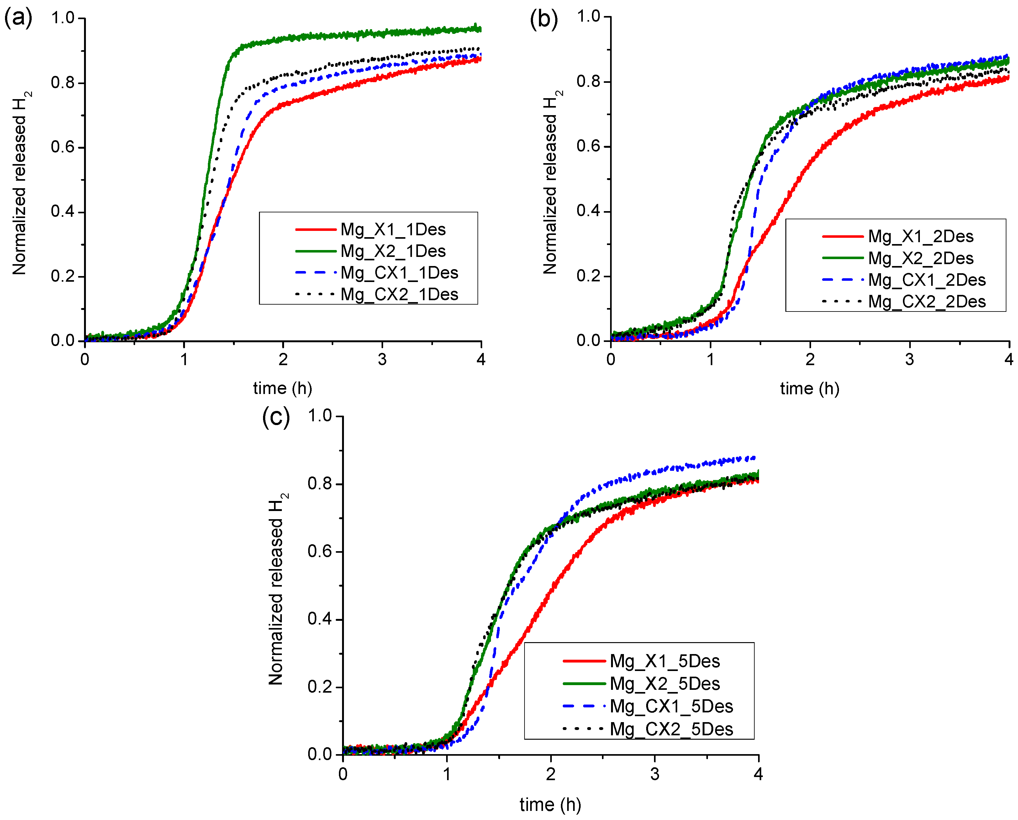
Figure 4.
Thermogravimetric and mass spectroscopic analysis of the hydrogen and butane release from as-prepared Mg_X2 (solid line) and cycled Mg_X2 (dash line) during constant heating from room temperature (RT) to 500 °C (ΔT/Δt = 5 °C/min).
Figure 4.
Thermogravimetric and mass spectroscopic analysis of the hydrogen and butane release from as-prepared Mg_X2 (solid line) and cycled Mg_X2 (dash line) during constant heating from room temperature (RT) to 500 °C (ΔT/Δt = 5 °C/min).
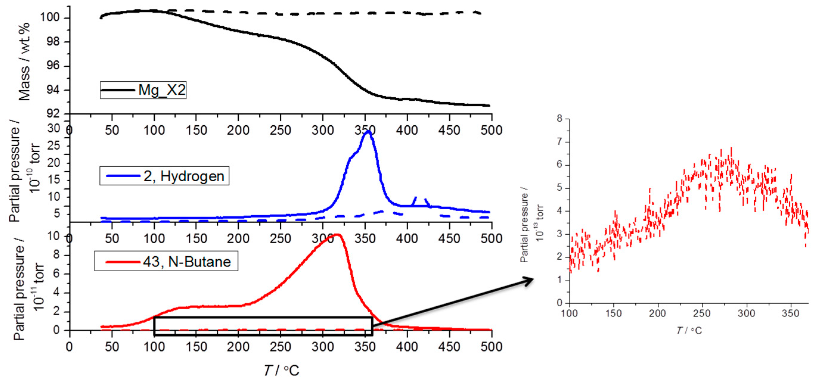
Figure 5.
Powder X-ray diffraction (PXD) of Mg_CX1 (a) before; and (b) after five desorption/absorption cycles. * MgH2; # MgO.
Figure 5.
Powder X-ray diffraction (PXD) of Mg_CX1 (a) before; and (b) after five desorption/absorption cycles. * MgH2; # MgO.

Figure 6.
Scanning transmission electron microscope-high-angle annular dark-field (STEM-HAADF) images and elemental mapping of the as-prepared Mg_CX2 (a,b) and Mg_CX2 after five desorption/absorption cycles (c,d).
Figure 6.
Scanning transmission electron microscope-high-angle annular dark-field (STEM-HAADF) images and elemental mapping of the as-prepared Mg_CX2 (a,b) and Mg_CX2 after five desorption/absorption cycles (c,d).

Table 1.
Texture properties of the carbon aerogel scaffolds and amount of magnesium hydride present after three infiltrations.
Table 1.
Texture properties of the carbon aerogel scaffolds and amount of magnesium hydride present after three infiltrations.
| Carbon Aerogels | SBET (m2/g) | Davg (nm) | Vmicro (cm3/g) | Vmeso (cm3/g) | Vtot (cm3/g) | MgH2 (wt %) a | MgH2 (vol %) b |
|---|---|---|---|---|---|---|---|
| X1 | 829 ± 16 | 16.6 ± 0.5 | 0.23 ± 0.01 | 1.13 ± 0.03 | 1.32 ± 0.04 | 24.8 | 17.3 |
| X2 | 801 ± 16 | 27.1 ± 2.7 | 0.25 ± 0.01 | 1.11 ± 0.08 | 1.32 ± 0.10 | 24.3 | 16.7 |
| CX1 | 1940 ± 131 | 14.7 ± 0.6 | 0.54 ± 0.07 | 1.85 ± 0.06 | 2.37 ± 0.12 | 37.1 | 17.1 |
| CX2 | 1803 ± 30 | 25.0 ± 0.8 | 0.56 ± 0.02 | 1.89 ± 0.04 | 2.38 ± 0.05 | 40.3 | 19.6 |
a Calculated stoichiometrically from the uptake of di-n-butylmagnesium; b Calculated from the volume of the empty scaffold and the bulk density of MgH2.
Table 2.
Calculated hydrogen content in infiltrated carbon aerogels and the hydrogen release measured by Sievert’s method in desorption one (Des1) to five (Des5) using condition 1. The percentages in parentheses correspond to the retained hydrogen storage capacity compared to the initial values in Des1.
| Sample | Dmax (nm) | ρm (H2)/(wt %) | Des1 (H2 wt %) | Des2 (H2 wt %) | Des3 (H2 wt %) | Des4 (H2 wt %) | Des5 (H2 wt %) |
|---|---|---|---|---|---|---|---|
| Mg_X1 | 17 | 1.88 | 1.8 (100%) | 1.3 (72%) | 1.2 (67%) | 1.2 (67%) | 1.2 (67%) |
| Mg_X2 | 26 | 1.85 | 1.3 (100%) | 1.2 (92%) | 1.1 (85%) | 1.1 (85%) | 1.0 (77%) |
| Mg_CX1 | 15 | 2.82 | 3.1 (100%) | 2.0 (67%) | 1.9 (61%) | 1.9 (61%) | 1.9 (61%) |
| Mg_CX2 | 25 | 3.06 | 2.2 (100%) | 1.4 (64%) | 1.3 (59%) | 1.2 (55%) | 1.2 (55%) |
Table 3.
Calculated average MgH2 crystallite size and crystalline weight fraction from PXD as infiltrated and after five desorption cycles using condition 1. The remaining crystalline weight fraction is from MgO, which in all cases exists with ~1 nm crystallites.
Table 3.
Calculated average MgH2 crystallite size and crystalline weight fraction from PXD as infiltrated and after five desorption cycles using condition 1. The remaining crystalline weight fraction is from MgO, which in all cases exists with ~1 nm crystallites.
| Sample | Dmax (nm) | As Infiltrated | After Five Cycles | ||
|---|---|---|---|---|---|
| MgH2 Cryst. Size (nm) | MgH2 Cryst. wt % | MgH2 Cryst. Size (nm) | MgH2 Cryst. wt % | ||
| Mg_X1 | 17 | 13 | 0.38 | 210 | 0.21 |
| Mg_X2 | 26 | 10 | 0.40 | 248 | 0.19 |
| Mg_CX1 | 15 | 8 | 0.48 | 300 | 0.35 |
| Mg_CX2 | 25 | 13 | 0.23 | 95 | 0.12 |
© 2017 by the authors. Licensee MDPI, Basel, Switzerland. This article is an open access article distributed under the terms and conditions of the Creative Commons Attribution (CC BY) license (http://creativecommons.org/licenses/by/4.0/).
Share and Cite
MDPI and ACS Style
Huen, P.; Paskevicius, M.; Richter, B.; Ravnsbæk, D.B.; Jensen, T.R. Hydrogen Storage Stability of Nanoconfined MgH2 upon Cycling. Inorganics 2017, 5, 57. https://doi.org/10.3390/inorganics5030057
AMA Style
Huen P, Paskevicius M, Richter B, Ravnsbæk DB, Jensen TR. Hydrogen Storage Stability of Nanoconfined MgH2 upon Cycling. Inorganics. 2017; 5(3):57. https://doi.org/10.3390/inorganics5030057
Chicago/Turabian StyleHuen, Priscilla, Mark Paskevicius, Bo Richter, Dorthe B. Ravnsbæk, and Torben R. Jensen. 2017. "Hydrogen Storage Stability of Nanoconfined MgH2 upon Cycling" Inorganics 5, no. 3: 57. https://doi.org/10.3390/inorganics5030057
Note that from the first issue of 2016, this journal uses article numbers instead of page numbers. See further details here.