The Versatile SALSAC Approach to Heteroleptic Copper(I) Dye Assembly in Dye-Sensitized Solar Cells


Department of Chemistry, University of Basel, Building 1096, Mattenstrasse 24a, CH-4058 Basel, Switzerland
*
Author to whom correspondence should be addressed.
Inorganics 2018, 6(2), 57; https://doi.org/10.3390/inorganics6020057
Submission received: 8 May 2018
/
Revised: 23 May 2018
/
Accepted: 23 May 2018
/
Published: 25 May 2018
(This article belongs to the Collection Coordination Complexes for Dye-Sensitized Solar Cells (DSCs))
Abstract
:Surface-bound heteroleptic copper(I) dyes [Cu(Lanchor)(Lancillary)]+ are assembled using the “surfaces-as-ligands, surfaces as complexes” (SALSAC) approach by three different procedures. The anchoring and ancillary ligands chosen are ((6,6′-dimethyl-[2,2′-bipyridine]-4,4′-diyl)-bis(4,1-phenylene))bis(phosphonic acid) (3) and 4,4′-bis(4-iodophenyl)-6,6′-diphenyl-2,2′-bipyridine (4), respectively. In the first SALSAC procedure, the FTO/TiO2 electrode is functionalized with 3 in the first dye bath, and then undergoes ligand exchange with the homoleptic complex [Cu(4)2][PF6] to give surface-bound [Cu(3)(4)]+. In the second method, the FTO/TiO2 electrode functionalized with 3 is immersed in a solution containing a 1:1 mixture of [Cu(MeCN)4][PF6] and 4 to give surface-anchored [Cu(3)(4)]+. In the third procedure, the anchor 3, copper(I) ion and ancillary ligand 4 are introduced in a sequential manner. The performances of the DSSCs show a dependence on the dye assembly procedure. The sequential method leads to the best-performing DSSCs with the highest values of JSC (7.85 and 7.73 mA cm−2 for fully masked cells) and overall efficiencies (η = 2.81 and 2.71%, representing 41.1 and 39.6% relative to an N719 reference DSSC). Use of the 1:1 mixture of [Cu(MeCN)4][PF6] and 4 yields DSSCs with higher VOC values but lower JSC values compared to those assembled using the sequential approach; values of η are 2.27 and 2.29% versus 6.84% for the N719 reference DSSC. The ligand exchange procedure leads to DSSCs that perform relatively poorly. The investigation demonstrates the versatile and powerful nature of SALSAC in preparing dyes for copper-based DSSCs, allowing the photoconversion efficiency of dye to be optimized for a given dye. The SALSAC strategy provides alternative hierarchical strategies where the isolation of the homoleptic [Cu(Lancillary)2]+ is difficult or time-consuming; stepwise strategies are more atom-economic than ligand exchange involving the homoleptic [Cu(Lancillary)2]+.
1. Introduction
Dye-sensitized solar cells (DSSCs) [1] harvest solar photons and convert them to electrical energy using a wide-bandgap semiconductor on which a dye is adsorbed [2,3,4]. The n-type semiconductor is usually nanoparticulate anatase (TiO2) and, ideally, the dye should be panchromatic, absorbing from the UV to near infrared. Photoconversion efficiencies (η) of up to ca. 14% have been achieved using organic, ruthenium(II) or zinc(II) porphyrin dyes [5,6,7,8,9,10]. However, ruthenium is not abundant in the Earth’s crust and this has encouraged us and others to explore the use of inorganic sensitizers containing more sustainable first-row metals such as copper(I) [11,12,13,14] and iron(II) [15,16]. Values of η in the range 3–5% [17,18,19] have been achieved for DSSCs containing copper(I) dyes. Although these values are lower than those for state-of-the-art ruthenium(II) dyes, we must appreciate that it has taken over 20 years to optimize ruthenium dye structures and their combination with I3−/I− electrolytes. In contrast, DSSCs sensitized with copper(I) dyes have only emerged in the last few years [11,12,13,14] and enhanced performances are gradually being achieved as a result of systematic modifications of dye and electrolyte components [17,20,21,22,23,24] and the use of co-sensitization [19]. The data points for 2017 in Figure 1 demonstrate that copper(I)-based DSSCs have achieved a relative photoconversion efficiency of 65.6% with respect to a reference DSSC sensitized with the ruthenium dye N719 (Scheme 1) [19].
Figure 1 summarizes the improvement in photoconversion efficiencies in copper-containing DSSCs relative to N719 reference cells. We include only our own results for sake of meaningful comparison, and data points are chosen for the best performing cells reported each year. Since 2013 [25], all DSSCs in Figure 1 have been fully masked [26]. Use of unmasked DSSCs leads to significant overestimation of performance; for example, Dragonetti et al. report a 25–30% decrease in η when a mask is applied to DSSCs containing copper dyes coupled with Cu2+/Cu+ electrolytes [23]. Figure 1 demonstrates that 2011 saw a landmark increase in η and this corresponded to a change from surface-bound homoleptic to surface-bound heteroleptic bis(diimine)copper(I) dyes. This approach predicates the use of heteroleptic complexes containing an anchoring ligand to bind to and facilitate electron-transfer to the semiconductor, and an ancillary ligand which influences the direction of electron flow from the excited state and facilitates hole-transfer to the electrolyte. Unfortunately, copper(I) complexes are labile and attempts to prepare heteroleptic [Cu(L1)(L2)]+ complexes in solution typically result in equilibrium mixtures of [Cu(L1)(L2)]+ and the homoleptic species [Cu(L1)2]+ and [Cu(L2)2]+ (Equation (1)) as shown by NMR spectroscopy [27].
2[Cu(L1)(L2)]+ ⇌ [Cu(L1)2]+ + [Cu(L2)2]+
To facilitate the preparation of heteroleptic complexes, Odobel and coworkers capitalized [18,28] upon the HETPHEN (HETeroleptic PHENanthroline) approach [29] in which bulky groups in the 6,6′-positions of a 2,2′-bipyridine (bpy) ligand stabilize the heteroleptic [Cu(L1)(L2)]+ with respect to ligand redistribution. Similar approaches have been introduced previously by, for example, Sauvage [30], Rehahn [31] and Swager [32]. Our analysis addressed the problem of ligand redistribution in a different manner. Instead of prioritizing the isolation of discrete heteroleptic complexes from solution, we recognized that the device relevant species was the surface-bound heteroleptic compound. This is encompassed in our “surfaces-as-ligands, surfaces as complexes” (SALSAC) approach in which the heteroleptic dye is assembled on the FTO/TiO2 electrode is a stepwise manner [11]. In this approach, the heteroleptic complex is essentially removed from equilibrium as a solid-state species with a solution activity of zero. In Figure 1, the first significant rise in photoconversion efficiency for DSSCs with copper(I) dyes was achieved [33] using SALSAC. For performance enhancement, heteroleptic dyes are essential. The SALSAC strategy is extremely adaptable, and has the added benefit of permitting dye regeneration [34,35].
Starting from a [Cu(bpy)2]+ core, the first requirements for the dye are substituents in the 6,6′-positions to stabilize the tetrahedral coordination geometry preferred by copper(I), and militate against the formation of square-planar copper(II) in both the ground and excited states [36]. Methyl groups are often selected, but use of 6,6′-diphenyl-2,2′-bipyridine has the advantage of extending the absorption range of the copper(I) complex towards the red as observed in the absorption spectrum of [Cu(dpp)2]+ (dpp = 2,9-diphenyl-1,10-phenanthroline) [37,38]. The second design feature to consider is the anchoring domain. Of the different anchors that we have investigated in copper(I) dyes, phosphonic acids (or phosphonates because the protonation state of the adsorbed anchor is not clear [39]) with a phenyl spacer between the PO(OH)2 and bpy units are superior to carboxylic and cyanoacrylic acids if one considers both synthetic accessibility and DSSC performance [40,41,42]. Finally, we come to the ancillary ligand where there is near-infinite scope for functional group modification. Despite investigating a wide range of functionalities for realizing “push–pull” dyes with improved DSSC performances, we have found that simple ancillaries often prove to be the most promising. Halo-substituents in Lancillary are not obvious contenders for inclusion in dyes, but DSSCs containing dyes with peripheral halo-substituents [17] or CF3 groups in the 6- or 6,6′-positions of the bpy unit [43] function surprisingly well.
We have previously demonstrated the beneficial effects of using ligands 1 and 2 (Scheme 2) as ancillary ligands with 3 as the anchoring ligand [17,40]. We now present an investigation of the effects on DSSC performance of combining 4,4′-bis(iodophenyl) and 6,6′-diphenyl substitution patterns in a bpy ancillary ligand 4, and also demonstrate the superiority of the SALSAC approach to the hierarchical assembly of copper(I) sensitizers on mesoporous TiO2 to optimize DSSC performance.
2. Results and Discussion
2.1. Ligand Synthesis and Characterization
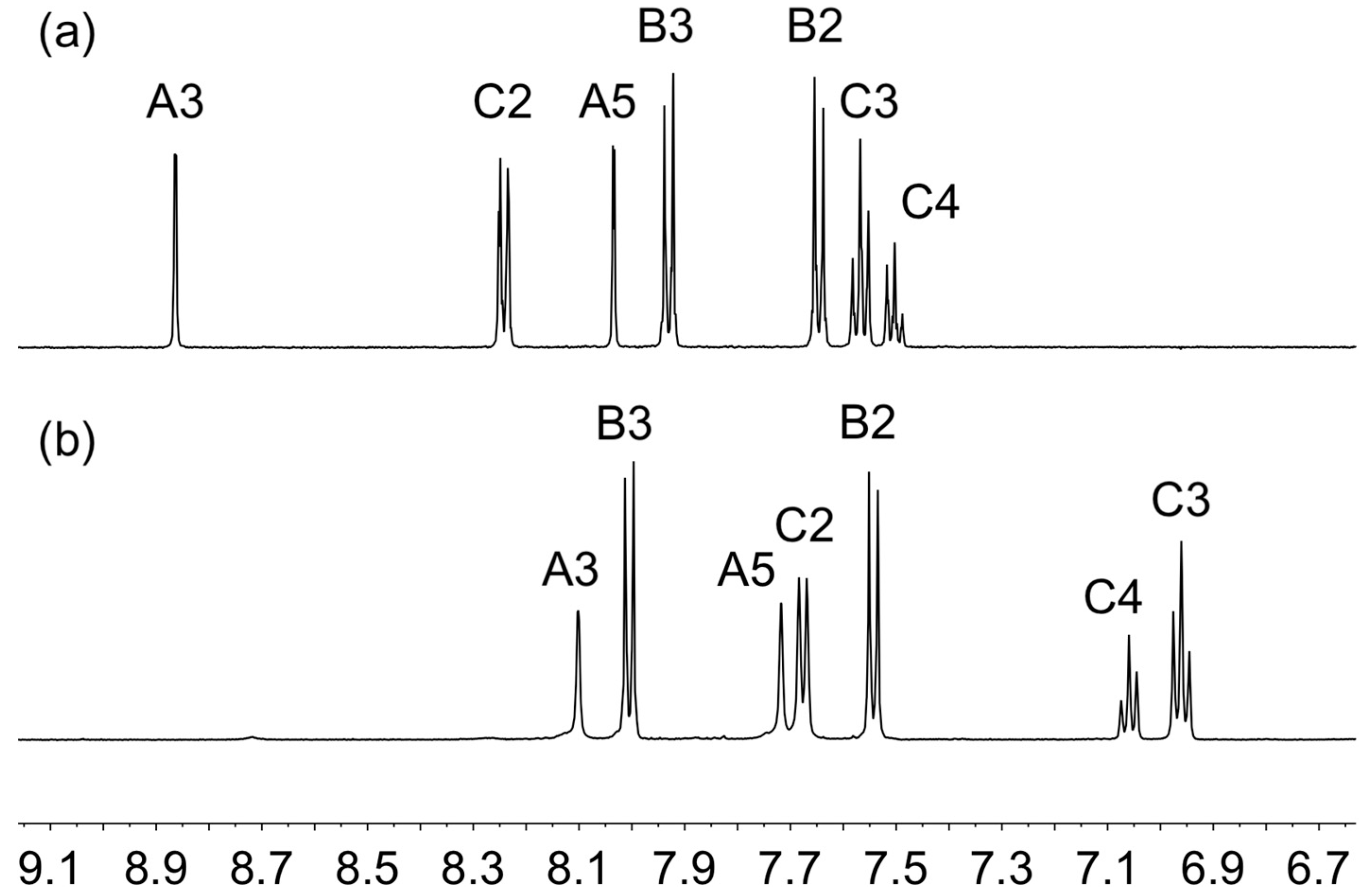
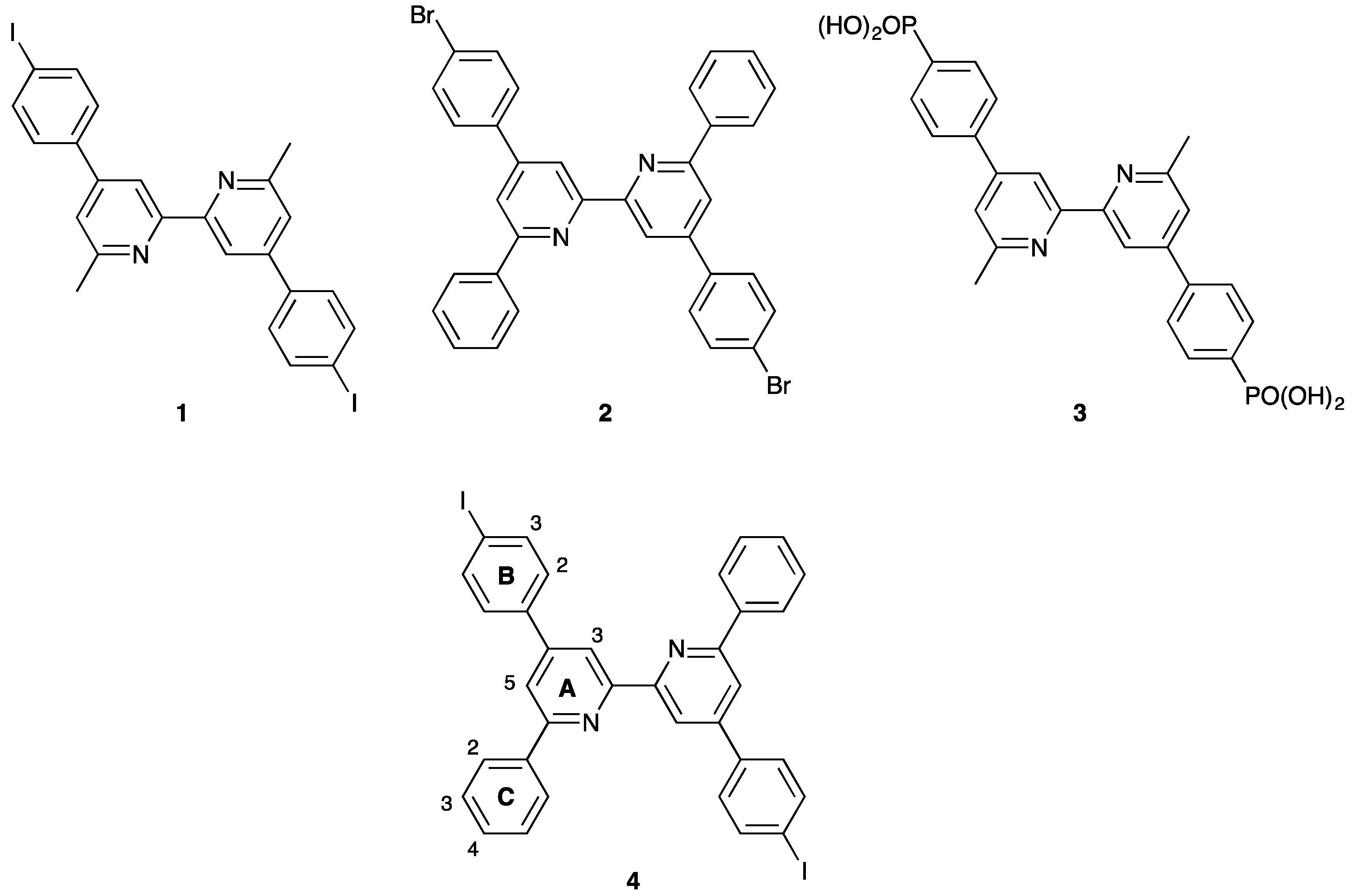
Anchoring ligand 3 was synthesized as previously described [40]. Ancillary ligand 4 was prepared using Kröhnke [44] methodology. The 1H NMR spectrum of 4 is shown in Figure 2a and this and the 13C NMR spectrum were assigned by COSY, NOESY, HMQC and HMBC methods; the atom labeling for assignments is given in Scheme 2. Signals for protons HA3 and HA5 were distinguished by the appearance of NOESY cross peaks between HC2 and HA5, and HB2 and HA3 (Figure S1). The electrospray mass spectrum of 4 exhibited a base peak at m/z = 713.3 arising from the [M + H]+ ion.
2.2. Synthesis and Characterization of [Cu(4)2][PF6]
The syntheses of homoleptic bis(bpy)copper(I) complexes with various bpy derivatives are typically carried out in a mixture of MeCN and CH2Cl2. However, when 4 and [Cu(MeCN)4][PF6] were combined in MeCN and CH2Cl2, no colour change was observed indicating that [Cu(4)2][PF6] was not formed. Significantly, reaction of two equivalents of 1 (Scheme 2) with [Cu(MeCN)4][PF6] in MeCN and CH2Cl2 resulted in a mixture of [Cu(1)2][PF6] and [Cu(1)(MeCN)2][PF6], rather than selective formation of [Cu(1)2][PF6] [17]. Nevertheless, the reaction of two equivalents of 4 with [Cu(MeCN)4][PF6] in CH2Cl2 yielded the dark red homoleptic complex [Cu(4)2][PF6] in quantitative yield.
The electrospray mass spectrum of [Cu(4)2][PF6] in the positive mode exhibited a base peak at m/z 1487.0 corresponding to the [Cu(4)2]+ ion. The 1H NMR spectrum of the compound is shown in Figure 2b. Assignments of the 1H and 13C NMR spectra were made using 2D techniques. A comparison of Figure 2a and 2b reveals significant shifts in proton signals on going from the free ligand 4 to [Cu(4)2][PF6]. The presence of the 6,6′-diphenyl substituents should lead to considerable flattening of the tetrahedral coordination sphere caused by π-stacking interactions between the phenyl substituents of one ligand with arene rings of the adjacent ligand, as has been crystallographically demonstrated for the related complex [Cu(1)2][PF6] (Scheme 1 shows ligand 1) [32]. The absorption spectrum of a CH2Cl2 solution of [Cu(4)2][PF6] (Figure 3) consists of intense bands in the UV region arising from ligand-centred π*←π transitions. As expected, the presence of the 6,6′-diphenyl substituents extends the absorption range giving two bands in the visible region (435 and 585 nm) as observed for the bromo-analogue [Cu(2)2][PF6] [40]. Similar dual bands in the visible have been described for [Cu(dpp)2]+ (dpp = 2,9-diphenyl-1,10-phenanthroline) and arise from the highly distorted and flattened structure caused by intramolecular π-stacking involving the phenyl substituents [37,38]. Interestingly, when a CH2Cl2 solution of [Cu(4)2][PF6] was left standing at room temperature, the colour changed from dark red to yellow over a 10 day period, and the dual absorptions in the visible were replaced with one, lower intensity maximum at 452 nm (Figure 3). This is consistent with the loss of the flattened structure and loss of one ligand 4 from the [Cu(4)2]+ ion. After 14 days, the solution was colourless with a small amount of greenish precipitate, and the absorption spectrum (Figure 3) showed complete loss of the MLCT band. The shift in the ligand-centred band to 270 nm (Figure 3) was consistent with the dominant solution species being compound 4 (Figure S5). An ESI mass spectrum of the 14 day old solution was dominated by a peak at m/z 713 corresponding to 4 (calculated [M + H]+ = 713).
The electrochemical behaviour of [Cu(4)2][PF6] was investigated by cyclic voltammetry and a comparison with the bromo-analogue [Cu(2)2][PF6] is given in Table 1. A reversible process at +0.36 V is assigned to the copper(I) oxidation in both cases. The oxidation potential is the same as for [Cu(2)2][PF6], consistent with the negligible effect of the remote iodo (in 4) versus bromo (in 2) substituents. An irreversible ligand-centred reduction is observed at −1.96 V.
2.3. The SALSAC Approach to On-Surface Dye Assembly
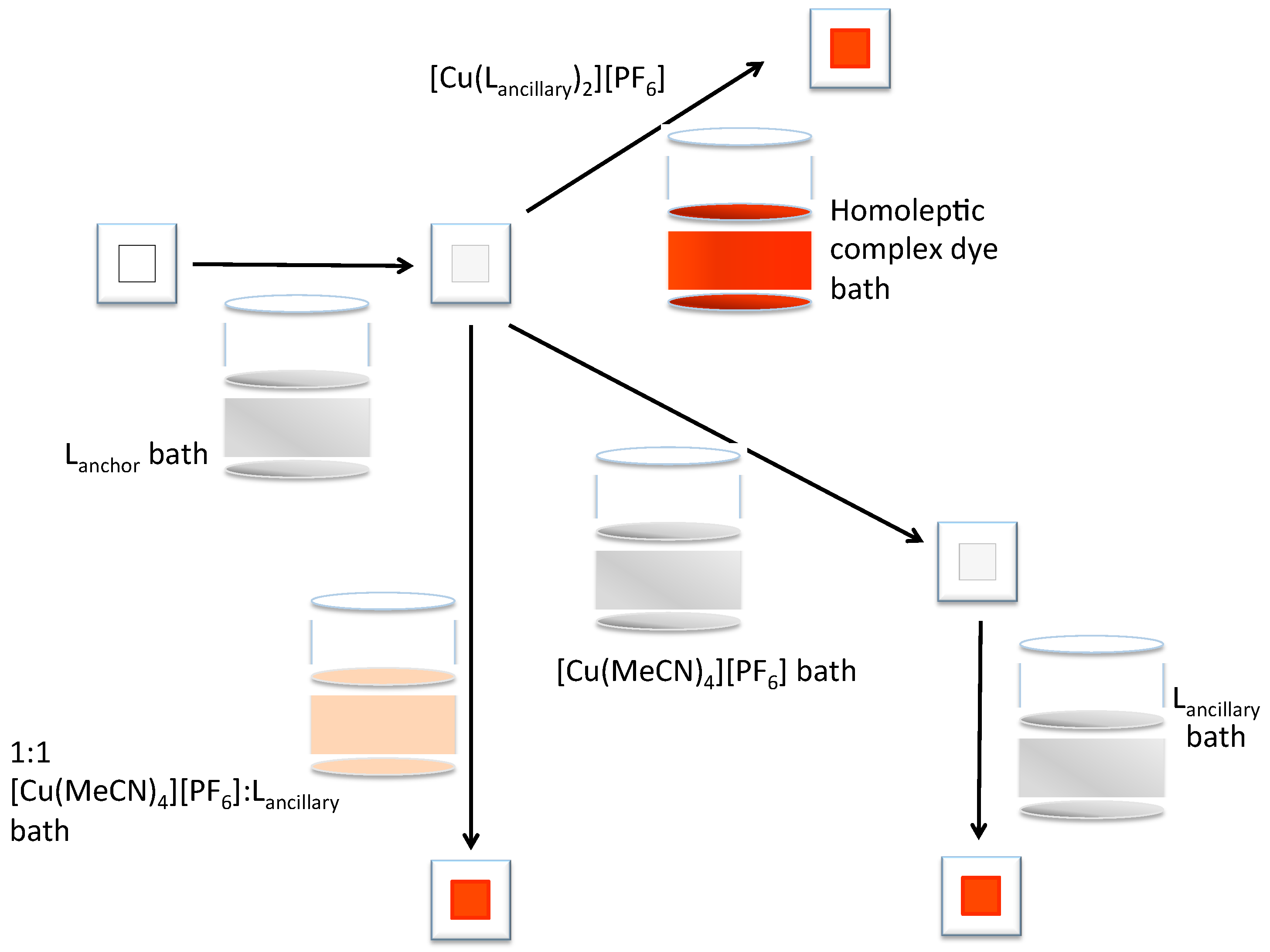
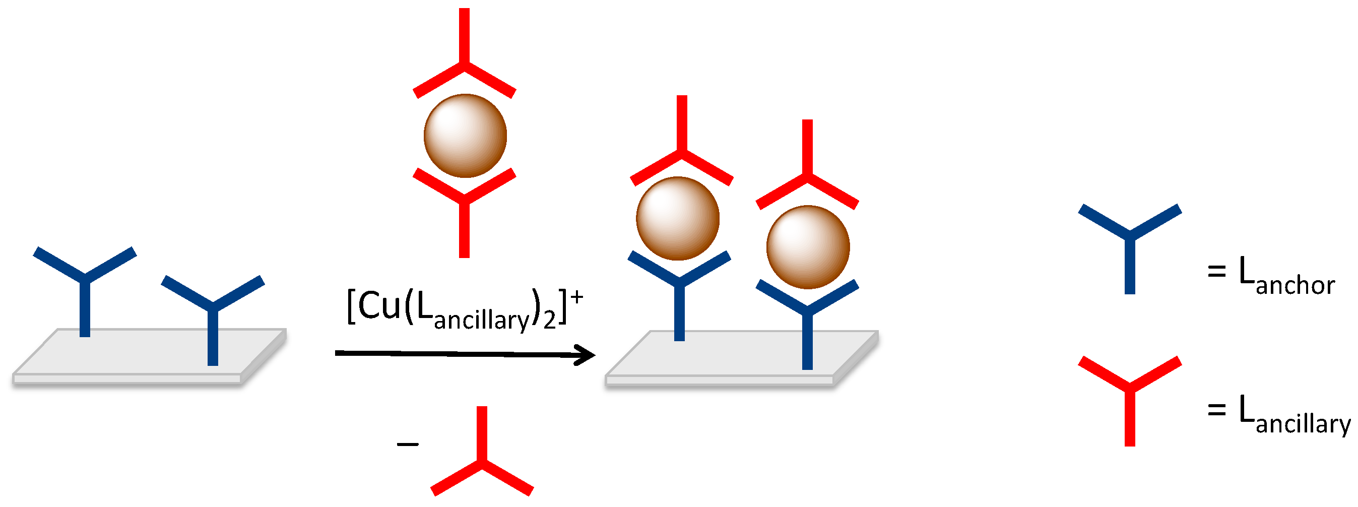
The first step in the SALSAC strategy for on-surface heteroleptic copper(I) dye assembly is the functionalization of the semiconductor surface with an anchoring ligand (Figure 4, top left). We have typically followed this with exposure of the ligand-functionalized surface to a solution of a homoleptic complex [Cu(Lancillary)2][PF6] which results in ligand exchange and the formation of a surface-bound heteroleptic species (Figure 4). This is a simple procedure that allows rapid screening of surface-bound heteroleptic dyes. A disadvantage, however, is that one equivalent of ancillary ligand is lost (Figure 5) and this is particularly detrimental if ligand synthesis is time-consuming, for example for ligands incorporating multiple-generation hole-transporting dendrons [25].
We have previously demonstrated that a mixture of [Cu(1)2][PF6] and [Cu(1)(MeCN)2][PF6] (see Scheme 1 for 1) can be used in place of pristine [Cu(1)2][PF6] in the assembly step shown at the top of Figure 4 using 3 as the anchoring ligand, Lanchor [17]. Furthermore, heteroleptic dyes may also be assembled by treating the anchor-functionalized TiO2 surface with a 1:1 mixture of [Cu(MeCN)4][PF6] and ancillary ligand (Figure 4, left) [17]. This procedure has the advantage of optimizing atom efficiency because no ancillary ligand is lost during surface-bound heteroleptic dye assembly. We confirmed that values of the current density (JSC) were similar for DSSCs with dyes assembled using a mixture of [Cu(1)2][PF6] and [Cu(1)(MeCN)2][PF6] or a 1:1 mixture of [Cu(MeCN)4][PF6] and 1 in the second dye bath (Figure 4). Values of the open-circuit voltage (VOC) were not significantly affected (range 551 to 582 mV). Overall, the photoconversion efficiencies did not show a significant dependence on the dye-assembly method [17]. The data are reproduced in Table 2 for convenience. While the data in Table 2 illustrate two variations of the SALSAC approach, a third variant is also possible involving the sequential exposure of the FTO/TiO2 electrode to anchoring ligand, followed by [Cu(MeCN)4][PF6], and finally the ancillary ligand (Figure 3, lower right). We were therefore motivated to compare the performances of DSSCs with dyes assembled using all three dipping processes shown in Figure 4, and chose to investigate the combination of anchor 3 with ancillary ligand 4. As a control, we also looked at the effects of treating the FTO/TiO2 working electrodes only with only [Cu(MeCN)4][PF6].
2.4. The SALSAC Approach to On-Surface Dye Assembly
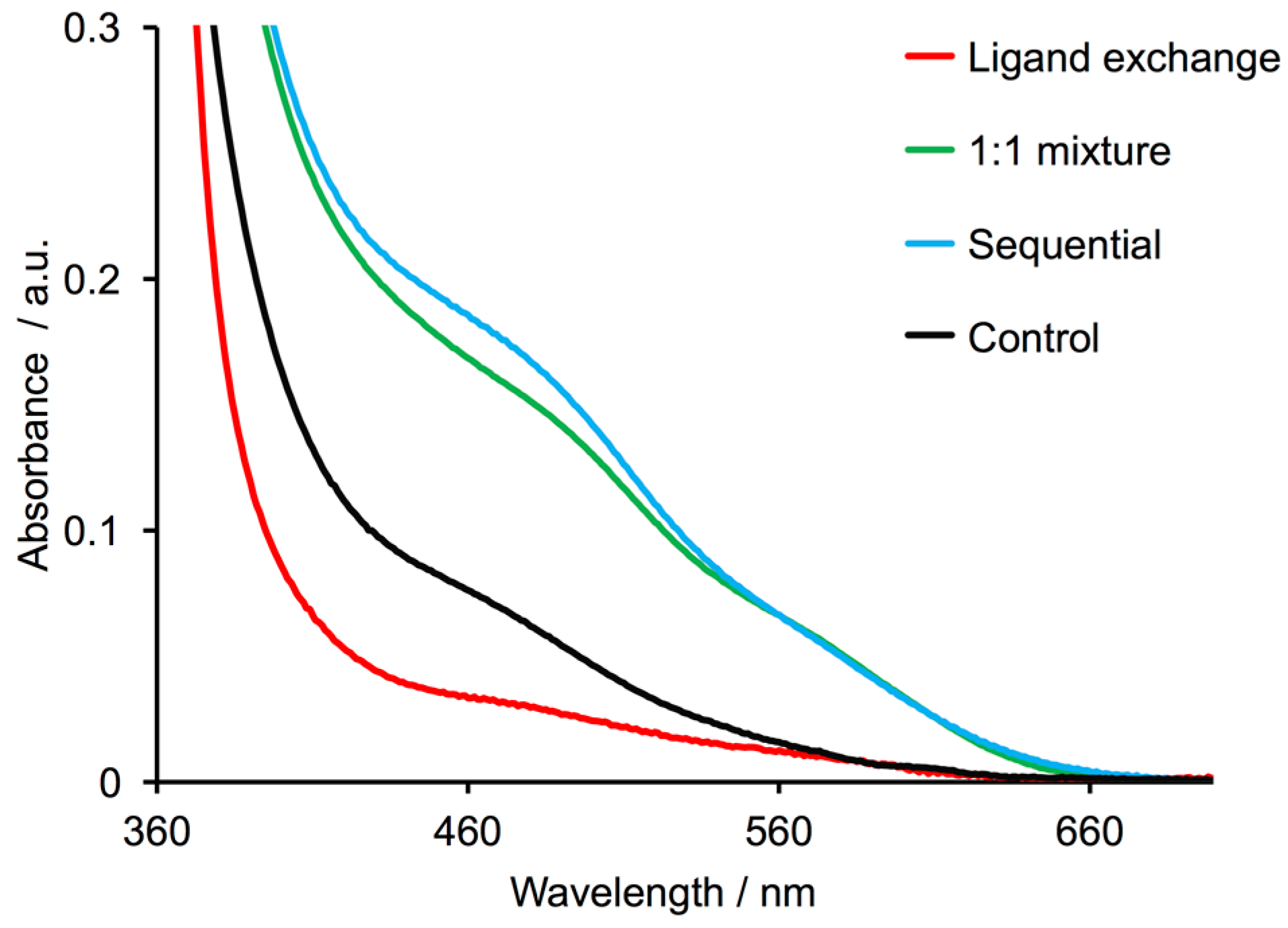
Figure 6 compares the solid-state absorption spectra of FTO/TiO2 electrodes (without a scattering layer) functionalized with anchor 3 followed by a solution of homoleptic complex [Cu(4)2][PF6] (ligand exchange strategy), or a 1:1 mixture of [Cu(MeCN)4][PF6] and 4, or sequential dye baths with [Cu(MeCN)4][PF6] and then 4. Use of the 1:1 dye bath or the sequential approach (Figure 4) leads to maxima in the absorption spectra at 480 nm arising from MLCT transitions of the anchored dye [Cu(3)(4)]+. Although the electrode functionalized using ligand exchange appeared orange to the eye, the corresponding absorption band at 480 nm is barely visible in Figure 6. The single absorption maximum is consistent with the heteroleptic complex [Cu(3)(4)]+ rather than [Cu(4)2]+ (see Section 2.2) because of the different 6,6′-substituents in ligands 3 and 4. As detailed in Section 2.2, the four phenyl substituents around the copper centre in [Cu(4)2]+ lead to a flattened structure and two bands in the visible region of the absorption spectrum. Ligand 3 has 6,6′-dimethyl substituents and the coordination environment around the copper(I) centre in [Cu(3)(4)]+ will be close to tetrahedral.
Given the mesoporous nature of the semiconductor surface and different orientations of anchored ligands 3 on the functionalized surface after the first dipping step (Figure 2), it is possible that some of the surface-anchored ligand 3 initially binds copper(I) to give anchored [Cu(3)2]+ in which both ligands 3 are bound to TiO2. Control experiments were carried out in which FTO/TiO2 electrodes without a scattering layer were immersed in a DMSO solution of anchor 3, followed by one day in a MeCN solution of [Cu(MeCN)4][PF6]. The appearance of an MLCT band at ca. 480 nm (Figure 6) indicates the formation of [Cu(3)2]+, presumably arising from the closure of two surface-bound ligands 3 around a Cu+ ion.
2.5. DSSC Performances
DSSCs sensitized with [Cu(3)(4)]+ were fabricated with working electrodes assembled using the three dipping procedures detailed in Figure 4. FTO/TiO2 electrodes with a scattering layer were subjected to the same dye-bath sequences detailed in Section 2.4 for the solid-state absorption spectroscopic measurements. For device measurements, the DSSCs were fully masked to prevent overestimation of their performance [26].
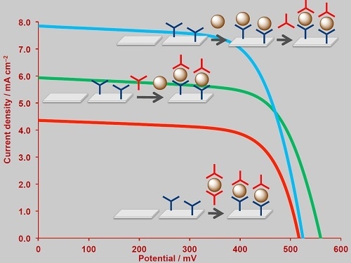
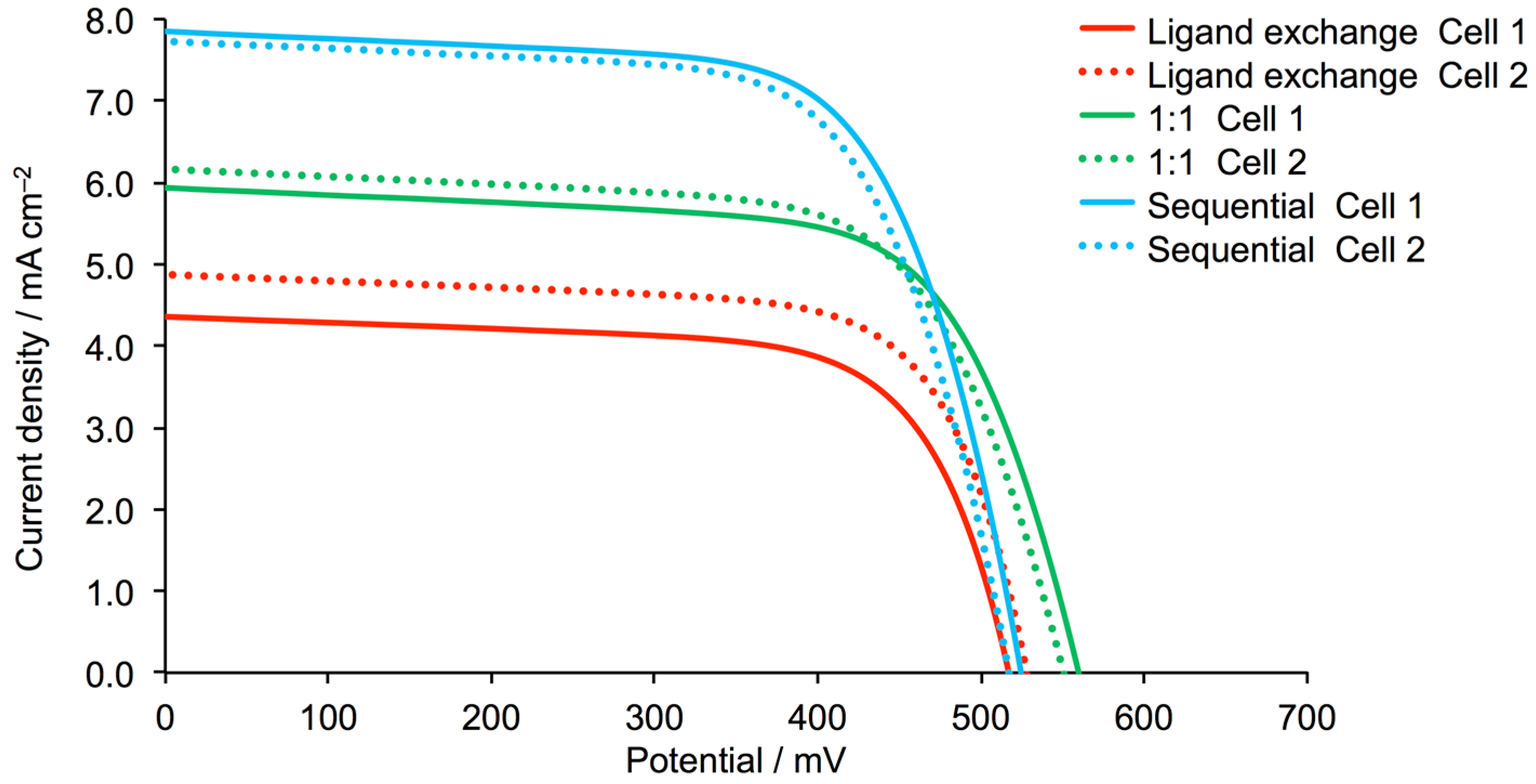
DSSC performance parameters for duplicate cells containing [Cu(3)(4)]+ are given in Table 3, and J–V curves measured on the day of device fabrication (day 0) are displayed in Figure 7. Figure S1 shows the J–V curves compared to that of an N719 reference cell. All fill factors are around 70%, providing approximately equal contributions to the global efficiencies (Equation (2)). Comparisons with a reference cell containing N719 are best made by setting the photoconversion efficiency of this cell to 100% (Table 3, right column). The trends in dependence of DSSC performance on method of dye assembly are confirmed by the use of multiple cells. The best-performing devices are those made using the three-step assembly process, with subsequent steps introducing sequentially the anchor 3, copper(I) centre and ancillary ligand 4. These DSSCs achieve values of JSC = 7.73 and 7.85 mA cm−2, respectively, and VOC = 524 and 517 mV, leading to overall conversion efficiencies of η = 2.81 and 2.71%, respectively. These values convert to 41.1 and 39.6% of η for the N719 reference. Significantly lower values of JSC are obtained by using a 1:1 mixture of [Cu(MeCN)4][PF6] and 4 in CH2Cl2 for the second dye-bath step, although a gain of ca. 35 mV in VOC is observed (Table 3). Overall, these DSSCs show photoconversion efficiencies relative to N719 of 33.2 and 33.4% (Table 3). Use of the ligand exchange procedure (Figure 4) leads to the lowest performing DSSCs. Although values of VOC are close to those of the DSSCs assembled by the sequential protocol, values of JSC are significantly lower (4.36 and 4.88 mA cm−2, Table 3 and Figure 7). The trends in JSC are consistent with the external efficiency (EQE) spectra (Figure 8 and Table 4). The observation that DSSC performance is significantly affected by the method used to assemble the dye on the semiconductor surface underlines a key advantage of the SALSAC approach in that the strategy can be adjusted to optimize DSSC performance on the day of cell fabrication.
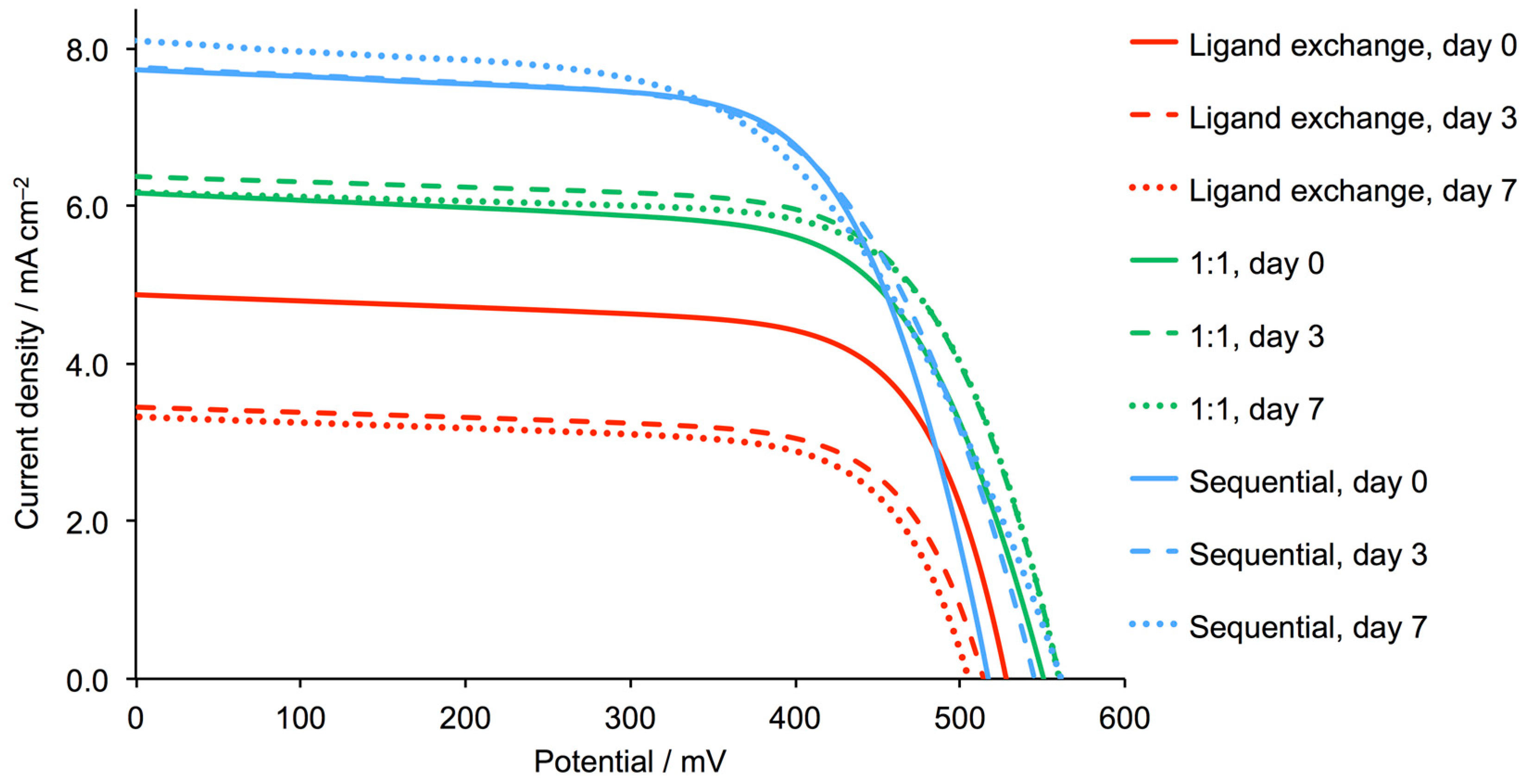
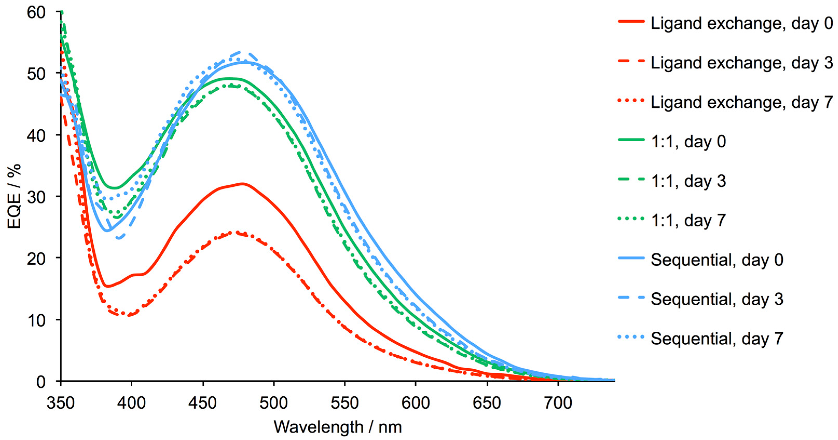
Performance parameters and EQE spectra for DSSCs sensitized by [Cu(3)(4)]+ were also measured after 3 and 7 days (Table 3 and Table S1). The devices were stored in the dark between measurements. DSSCs with dyes assembled using the sequential procedure or with the 1:1 mixture of [Cu(MeCN)4][PF6] and 4 are reasonably stable over a period of 7 days (Figure 9) whereas DSSCs containing dyes assembled using the homoleptic complex [Cu(4)2]+ exhibit reduced values of JSC after 3 days leading to lower photoconversion efficiencies. The reason for this is not clear. The fill factors remained around 68–70% indicating that cell integrity remained constant. The EQE spectra shown in Figure 10 are consistent with the trends in JSC values observed in the J–V curves in Figure 9. Table S1 gives values of EQEmax and λmax for the spectra in Figure 10.
As discussed in Section 2.3, solid-state absorption spectra indicated that [Cu(3)2]+ was present on the semiconductor surface after FTO/TiO2/3 electrodes were immersed in solutions of [Cu(MeCN)4][PF6]. A working electrode with a scattering layer was therefore prepared using this assembly procedure and incorporated into a DSSC. This control assesses the contribution of any [Cu(3)2]+ present in DSSCs. In principle, all the dye-assembly methods shown in Figure 4 could result in the formation of [Cu(3)2]+ as well as the desired [Cu(3)(4)]+. The control DSSC performed poorly, achieving values of JSC = 0.46 mA cm−2, VOC = 433 mV, ff = 41.6% and η = 0.08% on the day of sealing the cell. After 3 days, the same device exhibited values of JSC = 0.67 mA cm−2, VOC = 473 mV, ff = 51.2% and η = 0.16%. The J–V curves and EQE spectrum (λmax = 460 nm, EQEmax = 4.4%) are shown in Figures S3 and S4. The control experiment allows us to rule out [Cu(3)2]+ as an important active dye in DSSCs which use the SALSAC strategy with ligand 3 as an anchoring domain.
3. Materials and Methods
3.1. General
1H and 13C NMR spectra were recorded on a Bruker Avance III-500 NMR spectrometer (Bruker BioSpin AG, Fällanden, Switzerland); 1H and 13C chemical shifts were referenced to residual solvent peaks with respect to δ(TMS) = 0 ppm. Solution and solid-state absorption spectra were recorded using a Cary 5000 spectrophotometer (Agilent Technologies Inc., Santa Clara, CA, USA). Electrospray ionization (ESI) and high resolution ESI mass spectra were measured on a Shimadzu LCMS-2020 (Shimadzu Schweiz GmbH, Roemerstr, Switzerland), or Bruker maXis 4G QTOF instrument (Bruker Daltonics GmbH, Faellanden, Switzerland), respectively. Electrochemical measurements were made using a CH Instruments 900B potentiostat (CH Instruments, Inc., Austin, TX, USA) with glassy carbon, platinum wire and leakless AgCl/Ag+ electrode (eDAQ ET069, eDAQ Europe, Warszawa, Poland) as the working, counter and reference electrodes, respectively. Samples were dissolved in dry CH2Cl2 (10−4 to 10−5 mol dm−3) containing [nBu4N][PF6] (0.1 mol dm−3) as the supporting electrolyte; all solutions were degassed with argon. Cp2Fe was the internal reference.
3.2. Compound 4
1-(2-Oxo-2-phenylethyl)pyridin-1-ium bromide (0.814 g, 2.93 mmol, 2.5 equiv.) was dissolved in EtOH (30 mL) with vigorous stirring. (1E,5E)-1,6-bis(4-iodophenyl)hexa-1,5-diene-3,4-dione (0.600 g, 1.17 mmol, 1.0 equiv.) and ammonium acetate (1.35 g, 17.6 mmol, 15 equiv.) were added followed by additional EtOH (10 mL). The reaction mixture was then heated to reflux overnight (ca. 16 h). The reaction mixture was cooled to room temperature with stirring, and the precipitate that formed was separated by filtration and washed with cold EtOH. The precipitate was dried under an air stream, then redissolved in CH2Cl2. By adding EtOH, a white precipitate was formed that was filtered and washed with CH2Cl2. The solid was dried under vacuum. Compound 4 was isolated as an off-white solid (194 mg, 0.272 mmol, 23.3%). m.p. 334 °C. 1H NMR (500 MHz, CD2Cl2) δ/ppm 8.86 (d, J = 1.5 Hz, 2H, HA3), 8.24 (m, 4H, HC2), 8.03 (d, J = 1.5 Hz, 2H, HA5), 7.93 (d, J = 8.4 Hz, 4H, HB3), 7.65 (d, J = 8.5 Hz, 4H, HB2), 7.57 (t, J = 7.4 Hz, 4H, HC3), 7.50 (t, J = 7.3 Hz, 2H, HC4). 13C NMR (126 MHz, CDCl3) δ/ppm: 157.4 (CA6), 156.1 (CA2), 149.5 (CA4), 139.1 (CC1), 138.5 (CB3), 138.4 (CB1), 129.3 (CC4+B2), 129.0 (CC3), 127.4 (CC2), 118.8 (CA5), 118.0 (CA3), 95.3 (CB4). UV-VIS (CH2Cl2, 1.0 × 10⁻⁵ mol dm−3) λ/nm 270 (ε/dm3 mol−1 cm−1 90,600), 323 (18,800). ESI MS m/z positive mode 713.3 [M + H]+ (calc. 713.0). Found: C, 55.97, H, 3.20, N, 3.97; C34H22I2N2·H2O requires C, 55.91, H, 3.31, N, 3.84%.
3.3. Compound [Cu(4)2][PF6]
Compound 4 (15.0 mg, 0.0211 mmol) and [Cu(MeCN)4][PF6] (3.91 mg, 0.0105 mmol) were dissolved in CH2Cl2 (6 mL). The reaction mixture was stirred until full dissolution was observed. The solvent was removed under reduced pressure and the product was obtained as a dark red solid (17.1 mg, 0.0105 mmol, 100%). 1H NMR (500 MHz, CD2Cl2) δ / ppm 8.10 (s, 1H, HA3), 8.00 (d, J = 8.4 Hz, 2H, HB3), 7.72 (s, 1H, HA5), 7.68 (d, J = 7.3 Hz, 2H, HC2), 7.54 (d, J = 8.4 Hz, 2H, HB2), 7.06 (t, J = 7.4 Hz, 1H, HC4), 6.96 (t, J = 7.6 Hz, 2H, HC3). 13C NMR (126 MHz, CD2Cl2) δ/ppm 157.4 (CA6), 153.6 (CA2), 149.7 (CA4), 139.1 (CB3), 138.0 (CC1), 136.4 (CB1), 129.7 (CC4), 129.0 (CB2), 128.0 (CC2), 127.9 (CC3), 122.9 (CA5), 119.4 (CA3), 96.5 (CB4). UV-VIS (CH2Cl2, 1.0 × 10⁻⁵ mol dm−3) λ/nm 279 sh (ε/dm3 mol−1 cm−1 92,400), 299 (109,000), 340 sh (38,200), 435 (7270), 585 (4970). ESI MS m/z positive mode 1487.0 [M − PF6]+ (calc. 1486.9), negative mode 145.0 [PF6]− (calc. 145.0). HR ESI-MS m/z positive mode 1486.9011 [M − PF6]+ (calc. 1486.9035).
3.4. DSSC Fabrication
TiO2 electrodes (Solaronix Test Cell Titania Electrodes, Solaronix SA, Aubonne, Switzerland) were washed with milliQ water and HPLC grade EtOH, heated at 450 °C for 30 min, then cooled to ca. 80 °C. The electrodes were placed in a DMSO solution of 3 (1.0 mM) for 24 h at ambient temperature. The electrodes were taken out of the solution, washed with DMSO and EtOH, then dried in an N2 stream. For the ligand exchange method, each electrode was then immersed in a CH2Cl2 solution of [Cu(4)2][PF6] for 3 days at room temperature. For the 1:1 dipping procedure, each electrode was then immersed in a CH2Cl2 solution of a 1:1 mixture (each 0.1 mM) of 4 and [Cu(MeCN)4][PF6] for 3 days at room temperature. For the sequential assembly, each electrode was immersed in a MeCN solution of [Cu(MeCN)4][PF6] (2.0 mM) for 1 day followed by immersion in a CH2Cl2 solution of 4 (0.1 mM) for 3 days at room temperature. For the control, each FTO/TiO2/3 electrode was immersed for a day in a MeCN solution of [Cu(MeCN)4][PF6]. After removal from the final dye-bath, the electrodes were washed with CH2Cl2 and dried in an N2 stream. For N719 (Solaronix SA, Aubonne, Switzerland), TiO2 electrodes (Solaronix Test Cell Titania Electrodes, Solaronix SA, Aubonne, Switzerland) were soaked in a solution of N719 (EtOH, 0.3 mM) for 3 days. The electrodes were removed from the dye-bath, washed with EtOH and dried in a stream of N2. Counter electrodes (Solaronix Test Cell Platinum Electrodes, Solaronix SA, Aubonne, Switzerland) were washed with EtOH and then heated for 30 min at 450 °C to remove volatile organics.
Thermoplast hot-melt sealing foil (Solaronix Test Cell Gaskets, 60 µm, Solaronix SA, Aubonne, Switzerland) was used to connect the working and counter-electrodes, and the gap between them was filled with electrolyte (LiI (0.1 M), I2 (0.05 M), 1-methylbenzimidazole (0.5 M), 1-butyl-3-methylimidazolinium iodide (0.6 M) in 3-methoxypropionitrile) by vacuum backfilling through a hole in the counter-electrode. The hole was then sealed (Solaronix Test Cell Sealings and Solaronix Test Cell Caps, Solaronix SA, Aubonne, Switzerland).
3.5. Electrodes for Solid-State Absorption Spectroscopy
Dye-functionalized electrodes were assembled using the immersion procedures above (the same solution concentrations and times), but using Solaronix Test Cell Titania Electrodes Transparent (Solaronix SA, Aubonne, Switzerland).
3.6. DSSC and External Quantum Efficiency (EQE) Measurements
The DSSCs were masked; the mask was made from a black-coloured copper sheet with an aperture (ca. 0.06 cm2, each mask accurately calibrated) smaller than the surface area of TiO2. Black tape was used to complete the top and side masking of each DSSC. Performance measurements were made by irradiating the DSSC from behind with a LOT Quantum Design LS0811 instrument (LOT-QuantumDesign GmbH, Darmstadt, Germany, 100 mW cm−2 = 1 sun, AM1.5 G conditions) and the simulated light power was calibrated with a silicon reference cell.
EQE measurements were made using a Spe Quest quantum efficiency setup (Rera Systems, Nijmegen, The Netherlands) operating with a 100 W halogen lamp (QTH) and a lambda 300 grating monochromator (LOT-Oriel GmbH & Co. KG, Darmstadt, Germany). The monochromatic light was modulated to 3 Hz using a chopper wheel (ThorLabs Inc., Newton, NJ, USA), and the cell response was amplified with a large dynamic range IV converter (Melles Griot B.V., Didam, The Netherlands) and measured with a SR830 DSP Lock-In amplifier (Stanford Research Systems Inc., Sunnyvale, CA, USA).
4. Conclusions
We have reported the synthesis and characterization of ligand 4 and its homoleptic copper(I) complex. The solution absorption spectrum of [Cu(4)2][PF6] exhibits two MLCT bands at 435 and 585 nm, consistent with a flattened, tetrahedral structure in which there is intramolecular π-stacking involving the 6- and 6′-phenyl substituents. We have fabricated DSSCs in which the photoanode is sensitized with the heteroleptic copper(I) dye [Cu(3)(4)]+; the adsorbed dye is characterized by an MLCT band at ca. 480 nm. The FTO/TiO2 electrode surface was first functionalized with the phosphonic acid anchor 3, and then the dyes were assembled by ligand exchange using the homoleptic complex [Cu(4)2][PF6] or in a hierarchical manner using a 1:1 mixture of [Cu(MeCN)4][PF6] and 4, or sequential exposure to [Cu(MeCN)4][PF6] and then 4, thereby demonstrating the versatility of the SALSAC approach to the formation of surface-bound copper(I) dyes. The performances of the DSSCs show a marked dependence on the dye assembly procedure. Use of the sequential method leads to the best-performing DSSCs with the highest values of JSC (7.85 and 7.73 mA cm−2) and overall efficiencies (2.81 and 2.71% for masked cells versus 6.84% for a reference N719 DSSC). Using a 1:1 mixture of [Cu(MeCN)4][PF6] and 4 in the second dye bath (Figure 4) leads to DSSCs that have higher VOC values but lower JSC values compared to those assembled using the sequential dye baths. The net result is slightly reduced global efficiencies (2.27 and 2.29% versus 6.84% for the reference cell with N719). Both the sequential and 1:1 mixture approaches yield DSSCs that are stable over a 7 days period. In contrast, the ligand exchange procedure leads to devices that perform relatively poorly; values of JSC fall after 3 days from 4.36 and 4.88 mA cm−2 to 2.63 and 3.45 mA cm−2. Although the reasons why the ligand exchange protocol leads to inferior DSSCs are unclear, a contributing factor must be the presence of the 6,6′-diphenyl substitution pattern because, when phenyl groups are replaced by methyls (ligand 4 to 1, both the ligand exchange and use of the 1:1 mixture results in comparable DSSC performances (Table 3) [17].
This comparison of the three dye-assembly methods for surface-bound [Cu(3)(4)]+ demonstrates the powerful nature of SALSAC in preparing dyes for copper-based DSSCs. The approach allows us to optimize the conditions for the surface assembly of a particular dye and gives alternative hierarchical strategies where the isolation of the homoleptic [Cu(Lancillary)2]+ is difficult. The sequential approach has the advantage of being more atom-economic than ligand exchange involving the homoleptic [Cu(Lancillary)2]+.
Supplementary Materials
The following are available online at https://www.mdpi.com/2304-6740/6/2/57/s1. Figure S1: NOESY spectrum of ligand 4. Figure S2: J–V curves for duplicate DSSCs with photoanodes assembled using the three dipping methods (ligand exchange, 1:1 mixture and sequential). Figures S3 and S4: J–V curves and EQE spectra of the control DSSC. Figure S5: Solution absorption spectrum of 4. Table S1: EQE maxima for DSSCs on day 0, 3, and 7.
Author Contributions
F.J.M.: All experimental work and DSSC measurements, contributions to manuscript preparation; E.C.C.: group leader, project concepts and contributions to manuscript preparation; C.E.H.: group leader, project concepts and manuscript preparation.
Funding
We thank the Swiss National Science Foundation (Grant number 200020_162631) and the University of Basel for support.
Acknowledgments
Fabian Brunner (University of Basel) is thanked for assistance with electrochemical measurements.
Conflicts of Interest
The authors declare no conflicts of interest.
References
- O’Reagan, B.; Grätzel, M. A low-cost, high-efficiency solar cell based on dye-sensitized colloidal TiO2 films. Nature 1991, 353, 737–740. [Google Scholar] [CrossRef]
- Nazeeruddin, M.K.; Baranoff, E.; Grätzel, M. Dye-sensitized solar cells. A brief overview. Sol. Energy 2011, 85, 1172–1178. [Google Scholar] [CrossRef]
- Grätzel, M. Recent Advances in Sensitized Mesoscopic Solar Cells. Acc. Chem. Res. 2009, 42, 1788–1798. [Google Scholar] [CrossRef] [PubMed]
- Grätzel, M. Solar energy conversion by dye-sensitized photovoltaic cells. Inorg. Chem. 2005, 44, 6841–6851. [Google Scholar] [CrossRef] [PubMed]
- Yella, A.; Lee, H.W.; Tsao, H.N.; Yi, C.; Chandiran, A.K.; Nazeeruddin, M.K.; Diau, E.W.; Yeh, C.Y.; Zakeeruddin, S.M.; Grätzel, M. Porphyrin-sensitized solar cells with cobalt (II/III)-based redox electrolyte exceed 12 percent efficiency. Science 2011, 334, 629–634. [Google Scholar] [CrossRef] [PubMed]
- Higashino, T.; Imahori, H. Porphyrins as excellent dyes for dye-sensitized solar cells: Recent developments and insights. Dalton Trans. 2015, 44, 448–463. [Google Scholar] [CrossRef] [PubMed]
- Kakiage, K.; Aoyama, Y.; Yano, T.; Oya, K.; Kyomen, T.; Hanaya, M. Fabrication of a high-performance dye-sensitized solar cell with 12.8% conversion efficiency using organic silyl-anchor dyes. Chem. Commun. 2015, 51, 6315–6317. [Google Scholar] [CrossRef] [PubMed]
- Mathew, S.; Yella, A.; Gao, P.; Humphry-Baker, R.; Curchod, B.F.; Ashari-Astani, N.; Tavernelli, I.; Rothlisberger, U.; Nazeeruddin, M.K.; Grätzel, M. Dye-sensitized solar cells with 13% efficiency achieved through the molecular engineering of porphyrin sensitizers. Nat. Chem. 2014, 6, 242–247. [Google Scholar] [CrossRef] [PubMed] [Green Version]
- Xie, Y.; Tang, Y.; Wu, W.; Wang, Y.; Liu, J.; Li, X.; Tian, H.; Zhu, W.-H. Porphyrin Cosensitization for a Photovoltaic Efficiency of 11.5%: A Record for Non-Ruthenium Solar Cells Based on Iodine Electrolyte. J. Am. Chem. Soc. 2015, 137, 14055–14058. [Google Scholar] [CrossRef] [PubMed]
- Kakiage, K.; Aoyama, Y.; Yano, T.; Oya, K.; Fujisawa, J.-I.; Hanaya, M. Highly-efficient dye-sensitized solar cells with collaborative sensitization by silyl-anchor and carboxy-anchor dyes. Chem. Commun. 2015, 51, 15894–15897. [Google Scholar] [CrossRef] [PubMed]
- Housecroft, C.E.; Constable, C.E. The Emergence of copper(I)-based dye sensitized solar cells. Chem. Soc. Rev. 2015, 44, 8386–8398. [Google Scholar] [CrossRef] [PubMed] [Green Version]
- Magni, M.; Biagini, P.; Colombo, A.; Dragonetti, C.; Roberto, D.; Valore, A. Versatile copper complexes as a convenient springboard for both dyes and redox mediators in dyes sensiatized solar cells. Coord. Chem. Rev. 2016, 322, 69–93. [Google Scholar] [CrossRef]
- Lazorski, M.S.; Castellano, F.N. Advances in the light conversion properties of Cu(I)-based photosensitizers. Polyhedron 2014, 82, 57–70. [Google Scholar] [CrossRef]
- Sandroni, M.; Pellegron, Y.; Odobel, F. Heteroleptic bis-diimine copper(I) complexes for applications in solar energy conversion. Compt. Rendus Chim. 2016, 19, 79–93. [Google Scholar] [CrossRef]
- Jakubikova, E.; Bowman, D.N. Fe(II)-Polypyridines as Chromophores in Dye-Sensitized Solar Cells: A Computational Perspective. Acc. Chem. Res. 2015, 48, 1441–1449. [Google Scholar] [CrossRef] [PubMed]
- Liu, Y.; Persson, P.; Sundström, V.; Wärnmark, K. Fe N-Heterocyclic Carbene Complexes as Promising Photosensitizers. Acc. Chem. Res. 2016, 49, 1477–1485. [Google Scholar] [CrossRef] [PubMed]
- Malzner, F.J.; Brauchli, S.Y.; Constable, E.C.; Housecroft, C.E.; Neuburger, M. Halos show the path to perfection: Peripheral iodo-substituents improve the efficiencies of bis(diimine)copper(I) dyes in dye-sensitized solar cells. RSC Adv. 2014, 4, 48712–48723. [Google Scholar] [CrossRef]
- Sandroni, M.; Favereau, L.; Planchat, A.; Akdas-Kilig, H.; Szuwarski, N.; Pellegrin, Y.; Blart, E.; Le Bozec, H.; Boujtita, M.; Odobel, F. Heteroleptic copper(I)–polypyridine complexes as efficient sensitizers for dye sensitized solar cells. J. Mater. Chem. A 2014, 2, 9944–9947. [Google Scholar] [CrossRef]
- Malzner, F.J.; Willgert, M.; Constable, E.C.; Housecroft, C.E. The way to panchromatic copper(I)-based dye-sensitized solar cells: Co-sensitization with the organic dye SQ2. J. Mater. Chem. A 2017, 5, 13717–13729. [Google Scholar] [CrossRef]
- Fürer, S.O.; Bozic-Weber, B.; Schefer, T.; Wobill, C.; Constable, E.C.; Housecroft, C.E.; Willgert, M. Understanding why replacing I3–/I– by cobalt(II)/(III) electrolytes in bis(diimine)copper(I)-based dye-sensitized solar cells improves performance. J. Mater. Chem. A 2016, 4, 12995–13004. [Google Scholar] [CrossRef] [Green Version]
- Ashbrook, L.N.; Elliott, C.M. Dye-Sensitized Solar Cell Studies of a Donor-Appended Bis(2,9-dimethyl- 1,10-phenanthroline) Cu(I) Dye Paired with a Cobalt-Based Mediator. J. Phys. Chem. C 2013, 117, 3853–3864. [Google Scholar] [CrossRef]
- Fürer, S.O.; Luu, L.Y.N.; Bozic-Weber, B.; Constable, E.C.; Housecroft, C.E. Improving performance of copper(I)-based dye sensitized solar cells through I3–/I– electrolyte manipulation. Dyes Pigment. 2016, 132, 72–78. [Google Scholar] [CrossRef]
- Dragonetti, C.; Magni, M.; Colombo, A.; Melchiorre, F.; Biagini, P.; Roberto, D. Coupling of a Copper Dyes with a Copper Electrolyte: A Fascinating Springboard for Sustainable Dye-Sensitized Solar Cells. ACS Appl. Ener. Mater. 2018, 1, 751–756. [Google Scholar] [CrossRef]
- Karpacheva, M.; Malzner, F.J.; Wobill, C.; Büttner, A.; Constable, E.C.; Housecroft, C.E. Cuprophilia: Dye-sensitized solar cells with copper(I) dyes and copper(I)/(II) redox shuttles. Dyes Pigment. 2018, 156, 410–416. [Google Scholar] [CrossRef]
- Bozic-Weber, B.; Brauchli, S.Y.; Constable, E.C.; Fürer, S.O.; Housecroft, C.E.; Wright, I.A. Hole-transport functionalized copper(I) dye sensitized solar cells. Phys. Chem. Chem. Phys. 2013, 15, 4500–4504. [Google Scholar] [CrossRef] [PubMed]
- Snaith, H.J. How should you measure your excitonic solar cells? Energy Environ. Sci. 2012, 5, 6513–6520. [Google Scholar] [CrossRef]
- Hernandez Redondo, A.; Constable, E.C.; Housecroft, C.E. Towards sustainable dyes for dye-sensitized solar cells. Chimia 2009, 63, 205–207. [Google Scholar] [CrossRef]
- Sandroni, M.; Kayanuma, M.; Planchat, A.; Szuwarski, N.; Blart, E.; Pellegrin, Y.; Daniel, C.; Boujtita, M.; Odobel, F. First application of the HETPHEN concept to new heteroleptic bis(diimine) copper(I) complexes as sensitizers in dye sensitized solar cells. Dalton. Trans. 2013, 42, 10818–10827. [Google Scholar] [CrossRef] [PubMed]
- Kalsani, V.; Bodenstedt, H.; Fenske, D.; Schmittel, M. Supramolecular copper phenanthroline racks: Structures, mechanistic insight and dynamic Nature. Eur. J. Inorg. Chem. 2005, 10, 1841–1849. [Google Scholar] [CrossRef]
- Dietrich-Buchecker, C.O.; Sauvage, J.P.; Kintzinger, J.P. Une nouvelle famille de molecules: Les metallo-catenanes. Tetrahedron Lett. 1983, 24, 5095–5098. [Google Scholar] [CrossRef]
- Velten, U.; Rehahn, M. First synthesis of soluble, well defined coordination polymers from kinetically unstable copper(I) complexes. Chem. Commun. 1996, 23, 2639–2640. [Google Scholar] [CrossRef]
- Zhu, S.S.; Carroll, P.J.; Swager, T.M. Conducting polymetallorotazanes: A supramolecular approach to transition metal ion sensors. J. Am. Chem. Soc. 1996, 118, 8713–8714. [Google Scholar] [CrossRef]
- Bozic-Weber, B.; Constable, E.C.; Housecroft, C.E.; Kopecky, P.; Neuburger, M.; Zampese, J.A. The intramolecular aryl embrace: From light emission to light absorption. Dalton Trans. 2011, 40, 12584–12594. [Google Scholar] [CrossRef] [PubMed]
- Büttner, A.; Brauchli, S.Y.; Vogt, R.; Constable, E.C.; Housecroft, C.E. Combining phosphonic acid-functionalized anchoring ligands with asymmetric ancillary ligands in bis(diimine)copper(I) dyes for dye-sensitized solar cells. RSC Adv. 2016, 6, 5205–5213. [Google Scholar] [CrossRef] [Green Version]
- Brauchli, S.Y.; Malzner, F.J.; Constable, E.C.; Housecroft, C.E. Copper(I)-based dye-sensitized solar cells with sterically demanding anchoring ligands: Bigger is not always better. RSC Adv. 2015, 5, 48516–48525. [Google Scholar] [CrossRef]
- Eggleston, M.K.; McMillin, D.R.; Koenig, K.S.; Pallenberg, A.J. Steric Effects in the Ground and Excited States of Cu(NN)2+ Systems. Inorg. Chem. 1997, 36, 172–176. [Google Scholar] [CrossRef]
- Miller, M.T.; Gantzel, P.K.; Karpishin, T.B. Structures of the copper(I) and copper(II) complexes of 2,9-diphenyl-1,10-phenanthroline: Implications for excited-state structural distortion. Inorg. Chem. 1998, 37, 2285–2290. [Google Scholar] [CrossRef] [PubMed]
- Gushurst, A.K.I.; McMillin, D.R.; Dietrich-Buchecker, C.O.; Sauvage, J.P. Comparative studies of the photophysical properties of copper phenanthrolines: From Cu(dmp)2+ to the copper(I) catenates. Inorg. Chem. 1989, 28, 4070–4072. [Google Scholar] [CrossRef]
- Stephens, A.J.; Malzner, F.J.; Constable, E.C.; Housecroft, C.E. The influence of phosphonic acid protonation state on the efficiency of bis(diimine)copper(I) dye-sensitized solar cells. Sustain. Energy Fuels 2018, 2, 786–794. [Google Scholar] [CrossRef]
- Bozic-Weber, B.; Brauchli, S.Y.; Constable, E.C.; Fürer, S.O.; Housecroft, C.E.; Malzner, F.J.; Wright, I.A.; Zampese, J.A. Improving the photoresponse of copper(I) dyes in dye-sensitized solar cells by tuning ancillary and anchoring ligand modules. Dalton Trans. 2013, 42, 12293–12308. [Google Scholar] [CrossRef] [PubMed]
- Klein, Y.M.; Willgert, M.; Prescimone, A.; Constable, E.C.; Housecroft, C.E. Positional isomerism makes a difference: Phosphonic acid anchoring ligands with thienyl spacers in copper(I)-based dye-sensitized solar cells. Dalton Trans. 2016, 45, 4659–4672. [Google Scholar] [CrossRef] [PubMed] [Green Version]
- Baumgartner, Y.; Klein, Y.M.; Constable, E.C.; Housecroft, C.E.; Willgert, M. Cyanoacrylic- and (1-cyanovinyl)phosphonic acid anchoring ligands for application in copper-based dye-sensitized solar cells. RSC Adv. 2016, 6, 86220–86231. [Google Scholar] [CrossRef] [Green Version]
- Brunner, F.; Klein, M.; Keller, S.; Morris, C.D.; Prescimone, A.; Constable, E.C.; Housecroft, C.E. The beneficial effects of trifluoromethyl-substituents on the photoconversion efficiency of copper(I) dyes in dye-sensitized solar cells. RSC Adv. 2015, 5, 58694–58703. [Google Scholar] [CrossRef]
- Kröhnke, F. The specific synthesis of pyridines and oligopyridines. Synthesis. 1976, 1–24. [Google Scholar] [CrossRef]
- Kubas, G.J. Tetrakis(Acetonitrile)Copper(I) Hexafluorophosphate. Inorg. Synth. 1979, 19, 90–92. [Google Scholar] [CrossRef]
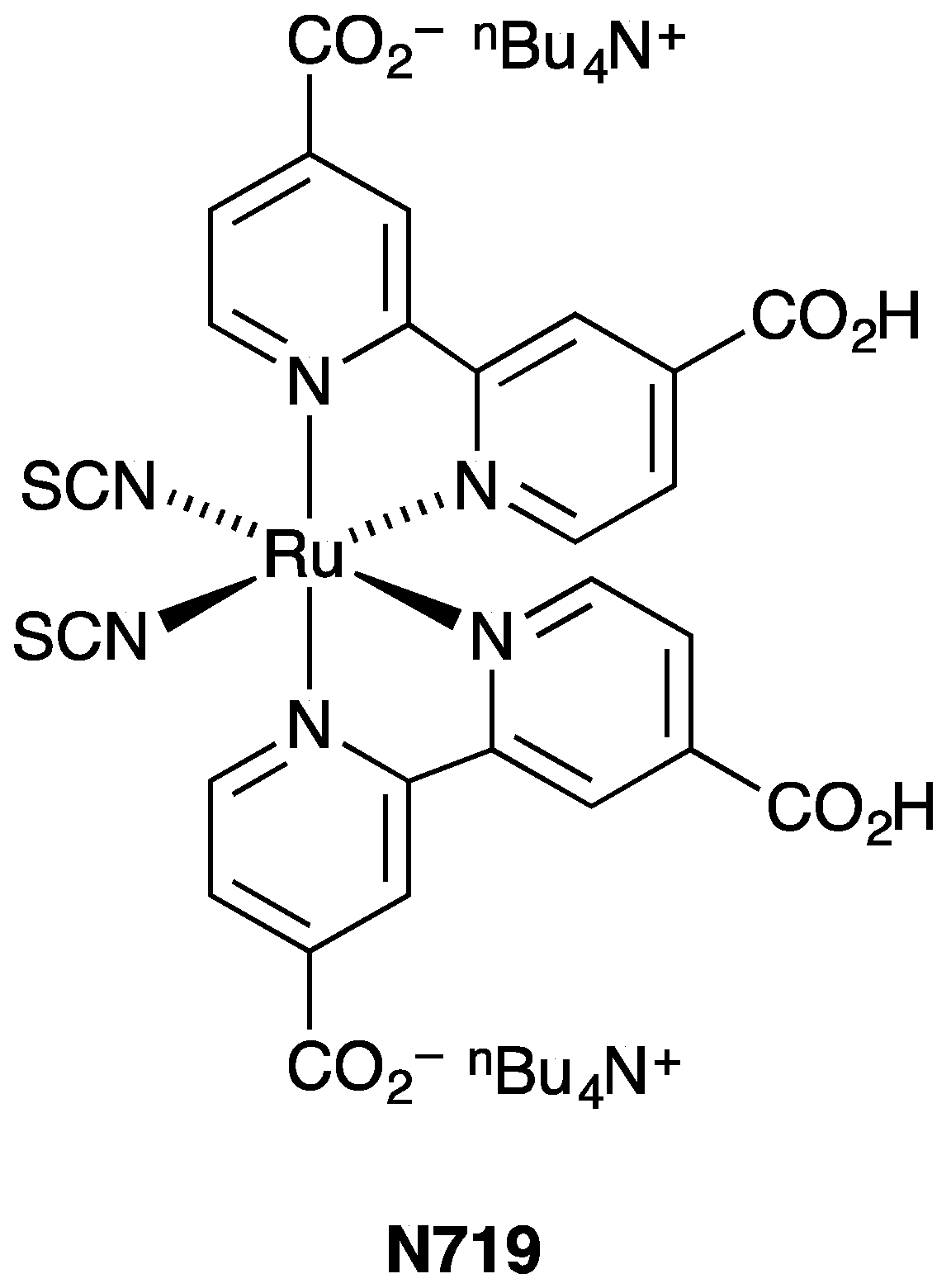
Scheme 1.
Structure of the reference dye N719.

Figure 1.
Progress of our own work in dye-sensitized solar cells (DSSCs) with copper(I) dyes presented in terms of photoconversion efficiencies relative to N719 set at 100%. Data points are chosen for the best performing cells reported each year.
Figure 1.
Progress of our own work in dye-sensitized solar cells (DSSCs) with copper(I) dyes presented in terms of photoconversion efficiencies relative to N719 set at 100%. Data points are chosen for the best performing cells reported each year.

Scheme 2.
Structures of ligands and atom labeling for NMR assignments of 4.

Figure 2.
1H NMR spectra (500 MHz, 298 K, CD2Cl2) of (a) 4 and (b) [Cu(4)2][PF6].

Figure 3.
Solution absorption spectra of (a) [Cu(4)2][PF6] (CH2Cl2, 1 × 10⁻⁵ mol dm−3) and (b) a comparison of CH2Cl2 solutions of [Cu(4)2][PF6] freshly made and after standing for 10 days.
Figure 3.
Solution absorption spectra of (a) [Cu(4)2][PF6] (CH2Cl2, 1 × 10⁻⁵ mol dm−3) and (b) a comparison of CH2Cl2 solutions of [Cu(4)2][PF6] freshly made and after standing for 10 days.


Figure 4.
Three approaches to heteroleptic copper(I) dye assembly using the “surfaces-as-ligands, surfaces as complexes” (SALSAC) strategy. See text for discussion.
Figure 4.
Three approaches to heteroleptic copper(I) dye assembly using the “surfaces-as-ligands, surfaces as complexes” (SALSAC) strategy. See text for discussion.

Figure 5.
The SALSAC approach to a TiO2-bound heteroleptic copper(I) dye using ligand exchange.

Figure 6.
Solid-state absorption spectra of FTO/TiO2 electrodes functionalized with anchor 3 followed by either a solution of homoleptic complex [Cu(4)2][PF6] (ligand exchange), or a 1:1 mixture of [Cu(MeCN)4][PF6] and 4, or sequential dye baths with [Cu(MeCN)4][PF6] and then 4, or only [Cu(MeCN)4][PF6] (control). See Materials and Methods for concentrations of solutions and times in the dye baths.

Figure 7.
J–V curves for duplicate DSSCs with photoanodes assembled using the three dipping methods (ligand exchange, 1:1 mixture and sequential) described in the Materials and Methods section.
Figure 7.
J–V curves for duplicate DSSCs with photoanodes assembled using the three dipping methods (ligand exchange, 1:1 mixture and sequential) described in the Materials and Methods section.

Figure 8.
External efficiency (EQE) spectra for DSSCs (cell 2 in each case, see Table 3) with photoanodes assembled using the three dipping methods (ligand exchange, 1:1 mixture and sequential) described in the Materials and Methods section.
Figure 8.
External efficiency (EQE) spectra for DSSCs (cell 2 in each case, see Table 3) with photoanodes assembled using the three dipping methods (ligand exchange, 1:1 mixture and sequential) described in the Materials and Methods section.

Figure 9.
J–V curves for DSSCs (cell 2 in each case, see Table 3) with photoanodes assembled using the three dipping methods described in the Materials and Methods section.
Figure 9.
J–V curves for DSSCs (cell 2 in each case, see Table 3) with photoanodes assembled using the three dipping methods described in the Materials and Methods section.

Figure 10.
EQE spectra for DSSCs (cell 2 in each case, see Table 3) with photoanodes assembled using the three assembly protocols described in the Materials and Methods section.
Figure 10.
EQE spectra for DSSCs (cell 2 in each case, see Table 3) with photoanodes assembled using the three assembly protocols described in the Materials and Methods section.


Table 1.
Cyclic voltammetric data for [Cu(4)2][PF6] compared to [Cu(2)2][PF6] with respect to Fc/Fc+; CH2Cl2 solutions with [nBu4N][PF6] as supporting electrolyte and scan rate of 0.1 V s−1. (irr = irreversible).
Table 1.
Cyclic voltammetric data for [Cu(4)2][PF6] compared to [Cu(2)2][PF6] with respect to Fc/Fc+; CH2Cl2 solutions with [nBu4N][PF6] as supporting electrolyte and scan rate of 0.1 V s−1. (irr = irreversible).
| Complex | /V (Epc − Epa/mV) | /V | Reference |
|---|---|---|---|
| [Cu(4)2][PF6] | +0.36 (49) | −1.96 irr | this work |
| [Cu(2)2][PF6] | +0.36 (86) | a | 40 |
a No reduction process observed within the solvent accessible window.
Table 2.
Performance parameters (under 1 sun illumination) of duplicate, masked DSSCs with [Cu(3)(1)]+ on the day of sealing the cells. The data are compared to a DSSC containing N719 and relative η values are with respect to N719 set at 100%. Data are from ref. [17].
Table 2.
Performance parameters (under 1 sun illumination) of duplicate, masked DSSCs with [Cu(3)(1)]+ on the day of sealing the cells. The data are compared to a DSSC containing N719 and relative η values are with respect to N719 set at 100%. Data are from ref. [17].
| Dye | Dipping Procedure a | Cell Number | On the Day of DSSC Fabrication | ||||
|---|---|---|---|---|---|---|---|
| JSC/mA cm−2 | VOC/mV | ff/% | η/% | Relative η/% | |||
| [Cu(3)(1)]+ | Ligand exchange | 1 | 6.68 | 582 | 74.0 | 2.88 | 38.8 |
| [Cu(3)(1)]+ | Ligand exchange | 2 | 6.92 | 576 | 72.6 | 2.89 | 38.9 |
| N719 b | - | - | 16.08 | 641 | 72.0 | 7.43 | 100 |
| [Cu(3)(1)]+ | 1:1 | 1 | 6.82 | 551 | 69.1 | 2.59 | 34.4 |
| [Cu(3)(1)]+ | 1:1 | 2 | 7.01 | 559 | 70.2 | 2.75 | 36.5 |
| N719 c | - | - | 16.88 | 641 | 69.6 | 7.54 | 100 |
a “Ligand exchange” uses a mixture of [Cu(1)2][PF6] and [Cu(1)(MeCN)2][PF6] in CH2Cl2; ‘1:1′ uses a 1:1 mixture of [Cu(MeCN)4][PF6] and 1 (Figure 2). b N719 DSSC used for the ligand exchange experiments. c N719 DSSC used for the 1:1 mixture experiments.
Table 3.
Performance parameters (under 1 sun illumination) of duplicate, masked DSSCs with [Cu(3)(4)]+ on the day of sealing the cells, and after 3 and 7 days. The data are compared to a DSSC containing N719 and relative η values are with respect to N719 set at 100%.
Table 3.
Performance parameters (under 1 sun illumination) of duplicate, masked DSSCs with [Cu(3)(4)]+ on the day of sealing the cells, and after 3 and 7 days. The data are compared to a DSSC containing N719 and relative η values are with respect to N719 set at 100%.
| Dye | Dipping Procedure a | Cell Number | On the Day of DSSC Fabrication | ||||
| JSC/mA cm−2 | VOC/mV | ff/% | η/% | Relative η/% | |||
| [Cu(3)(4)]+ | Ligand exchange | 1 | 4.36 | 517 | 69.0 | 1.55 | 22.7 |
| [Cu(3)(4)]+ | Ligand exchange | 2 | 4.88 | 528 | 70.1 | 1.80 | 26.4 |
| [Cu(3)(4)]+ | 1:1 | 1 | 5.95 | 560 | 68.2 | 2.27 | 33.2 |
| [Cu(3)(4)]+ | 1:1 | 2 | 6.17 | 550 | 67.3 | 2.29 | 33.4 |
| [Cu(3)(4)]+ | Sequential | 1 | 7.85 | 524 | 68.3 | 2.81 | 41.1 |
| [Cu(3)(4)]+ | Sequential | 2 | 7.73 | 517 | 67.8 | 2.71 | 39.6 |
| N719 | - | - | 15.33 | 615 | 72.6 | 6.84 | 100 |
| Dye | Dipping Procedure a | Cell Number | 3 Days after DSSC Fabrication | ||||
| JSC/mA cm−2 | VOC/mV | ff/% | η/% | Relative η/% | |||
| [Cu(3)(4)]+ | Ligand exchange | 1 | 2.63 | 499 | 67.8 | 0.89 | 12.2 |
| [Cu(3)(4)]+ | Ligand exchange | 2 | 3.45 | 514 | 69.4 | 1.23 | 16.8 |
| [Cu(3)(4)]+ | 1:1 | 1 | 5.69 | 560 | 69.4 | 2.21 | 30.2 |
| [Cu(3)(4)]+ | 1:1 | 2 | 6.38 | 560 | 68.9 | 2.46 | 33.7 |
| [Cu(3)(4)]+ | Sequential | 1 | 6.58 | 515 | 71.4 | 2.42 | 33.1 |
| [Cu(3)(4)]+ | Sequential | 2 | 7.77 | 545 | 63.7 | 2.69 | 36.8 |
| N719 | 15.73 | 638 | 72.9 | 7.31 | 100 | ||
| Dye | Dipping Procedure a | Cell Number | 7 Days after DSSC Fabrication | ||||
| JSC/mA cm−2 | VOC/mV | ff/% | η/% | Relative η/% | |||
| [Cu(3)(4)]+ | Ligand exchange | 1 | 2.61 | 501 | 68.1 | 0.89 | 12.1 |
| [Cu(3)(4)]+ | Ligand exchange | 2 | 3.33 | 505 | 69.0 | 1.16 | 15.7 |
| [Cu(3)(4)]+ | 1:1 | 1 | 5.60 | 561 | 70.6 | 2.22 | 30.1 |
| [Cu(3)(4)]+ | 1:1 | 2 | 6.18 | 560 | 70.2 | 2.43 | 32.9 |
| [Cu(3)(4)]+ | Sequential | 1 | 7.13 | 535 | 69.4 | 2.65 | 35.9 |
| [Cu(3)(4)]+ | Sequential | 2 | 8.10 | 561 | 57.6 | 2.61 | 35.5 |
| N719 | 15.16 | 672 | 72.4 | 7.37 | 100.0 | ||
a See text for definitions of “1:1” and “sequential” dipping procedures.
Table 4.
EQE maxima for duplicate DSSCs containing dyes [Cu(3)(4)]+ on the day of cell fabrication compared to N719.
Table 4.
EQE maxima for duplicate DSSCs containing dyes [Cu(3)(4)]+ on the day of cell fabrication compared to N719.
| Cell Number | Dipping Procedure a | λmax/nm | EQEmax/% |
|---|---|---|---|
| 1 | Ligand exchange | 480 | 29.8 |
| 2 | Ligand exchange | 480 | 31.9 |
| 1 | 1:1 | 470 | 47.0 |
| 2 | 1:1 | 470 | 49.1 |
| 1 | Sequential | 460 | 52.5 |
| 2 | Sequential | 480 | 51.7 |
| N719 | 540 | 68.5 |
a See text for definitions of ligand exchange, 1:1 and sequential dipping procedures.
© 2018 by the authors. Licensee MDPI, Basel, Switzerland. This article is an open access article distributed under the terms and conditions of the Creative Commons Attribution (CC BY) license (http://creativecommons.org/licenses/by/4.0/).
Share and Cite
MDPI and ACS Style
Malzner, F.J.; Housecroft, C.E.; Constable, E.C. The Versatile SALSAC Approach to Heteroleptic Copper(I) Dye Assembly in Dye-Sensitized Solar Cells. Inorganics 2018, 6, 57. https://doi.org/10.3390/inorganics6020057
AMA Style
Malzner FJ, Housecroft CE, Constable EC. The Versatile SALSAC Approach to Heteroleptic Copper(I) Dye Assembly in Dye-Sensitized Solar Cells. Inorganics. 2018; 6(2):57. https://doi.org/10.3390/inorganics6020057
Chicago/Turabian StyleMalzner, Frederik J., Catherine E. Housecroft, and Edwin C. Constable. 2018. "The Versatile SALSAC Approach to Heteroleptic Copper(I) Dye Assembly in Dye-Sensitized Solar Cells" Inorganics 6, no. 2: 57. https://doi.org/10.3390/inorganics6020057
Note that from the first issue of 2016, this journal uses article numbers instead of page numbers. See further details here.