The Effect of Illumination Direction and Temperature on Dye-Sensitized Solar Cells with Viscous Cobalt Complex-Based Electrolytes


Department of Chemistry-Ångström Laboratory, Uppsala University, 75120 Uppsala, Sweden
*
Authors to whom correspondence should be addressed.
Inorganics 2018, 6(2), 60; https://doi.org/10.3390/inorganics6020060
Submission received: 7 May 2018
/
Revised: 5 June 2018
/
Accepted: 6 June 2018
/
Published: 12 June 2018
(This article belongs to the Collection Coordination Complexes for Dye-Sensitized Solar Cells (DSCs))
Abstract
:The illumination direction and temperature can greatly affect the performance of dye-sensitized solar cells (DSSCs) when practical non-volatile solvents are used with bulky one-electron redox mediators such as cobalt tris(bipyridine). For higher performance, a tandem electrolyte system consisting of cobalt tris(bipyridine) with tris(4-methoxyphenyl)amine was used. Discrepancies in J–V hysteresis were investigated by using photocurrent turn-on transients, open-circuit voltage decay, and electrochemical impedance spectroscopy. The devices perform much better upon illumination form the counter electrode side and exhibit much less hysteresis and more stabilized power output as characterized by maximum power-point tracking (MPP) tracking.
1. Introduction
Research interest in dye-sensitized solar cells has recently peaked following the introduction of a cobalt tris(bipyridine) redox mediator. Traditionally, iodide/triiodide-based electrolytes have been used in dye-sensitized solar cells (DSSCs) to regenerate the oxidized dye molecules created after photoinduced electron injection as well as to transport the positive charge away from the mesoporous TiO2 electrode to the counter electrode [1,2]. Recent findings demonstrate that higher power conversion efficiencies (PCE) can be achieved in DSSCs with alternative one-electron redox mediators, which have exceeded efficiencies of 14% for cobalt tris(bipyridine) complex mediators [3,4,5]. More recently, it was demonstrated that a tandem redox system, which combines the Co(bpy)32+/3+ redox mediator with a redox intermediate, tris(4-methoxyphenyl)amine (TPAA), can greatly enhance dye regeneration (ns timescale) and boost device performance [6].
However, one major caveat is that all the record efficiencies in DSSC have been obtained using electrolytes based on volatile and toxic acetonitrile solvents (ACN), which provides better performance due to its lower viscosity. To upscale and commercialize, DSSC modules will need to be fabricated with more practical non-volatile and labile electrolytes, such as ionic liquids or 3-methoxypropionitrile (MPN) [7]. Furthermore, several studies have introduced additives into the electrolyte to reduce electrolyte volatility through gelation of the electrolyte [8,9,10]. These greatly improve the thermal stability of the electrolyte [11], albeit at the cost of increasing the viscosity, which substantially contributes to inferior mass transport of the redox mediator. Although such issues have long been present for monolithic iodide redox mediators, this becomes dramatically worse for the bulkier metal complex electrolytes, which tend to have much lower diffusion coefficients as well as lower solubility. Diffusion coefficients for Co(bpy)32+ in MPN and ACN are 2.6 and 8.7 × 10⁻⁶ cm2·s−1, respectively, and, in ionic liquids, about one order of magnitude lower than the MPN value [12,13].
Additionally, much of the above work dedicated towards reducing electrolyte volatility has been almost exclusively conducted on iodide-based electrolytes. Unfortunately, there has been relatively little progress towards replacing acetonitrile whilst maintaining high performance. There have been some attempts to reduce the volatility of cobalt-acetonitrile electrolytes through the addition of gelling agents [14,15]. A PCE of 7.37% was obtained for an ionic liquid electrolyte system with a dual redox system consisting of imidazolium functionalized cobalt trisbipyridine complexes and iodide/triiodide [16]. For aqueous cobalt-based electrolytes, a PCE of >5% has been obtained; however, further improvements have been limited by redox mediator solubility and compatible dyes, which can sufficiently facilitate electrolyte infiltration of the mesoporous TiO2 film [17,18,19]. Finally, in lower temperatures, which is a relevant real-world operating condition for DSSCs, the present limitations of mass transport mentioned in the abovementioned works would be further exacerbated. This is problematic, given that the performance of DSSCs can usually be enhanced by heating [14,18], and the majority of the literature does not usually disclose the temperature testing conditions for J–V measurements.
In recent work, we reported on the impact of non-uniform photogeneration in dye-sensitized solar cells with Co(bpy)3 electrolyte [20]. The spatial photogeneration profile of both electrons Co(bpy)33+ species throughout the mesoporous TiO2 electrode is highly dependent on the wavelength and direction of incoming light, which was found to have a marked impact on mass transport limitations.
In this work, we report on the effect of temperature on DSSC with tandem TPAA-cobalt complex-based electrolytes, with a viscous 3-methoxypropionitrile solvent. We demonstrate that, despite clear mass transport limitations, substantially greater device performance can be obtained by illumination from the counter electrode side. Also, the performance of solar cell device is typically determined from a linear voltage sweep measurement and compared as a current-voltage graph. However, inaccuracies can arise from an insufficiently long sampling delay time, which needs to exceed the time constant of the device. This particularly affects DSSCs, which tend to respond much slower to a step-wise change in voltage when compared to typical silicon-based solar cells [21,22,23]. Improper selection of additional parameters, such as the pre-scanning conditions, initial scan voltage and scan direction, can result in discrepancies between subsequent J–V measurements. The so-called J–V “hysteresis” typically compares such differences resulting from different scan directions, such as forward bias scan direction and reverse bias scan direction. In principle, J–V hysteresis can be minimized by lowering the voltage step and increasing the sampling time; however, this can lead to extremely long measurements. In this work, the effect of lower temperatures and illumination direction on subsequent J–V hysteresis and maximum power point stabilization is also examined.
2. Results and Discussion
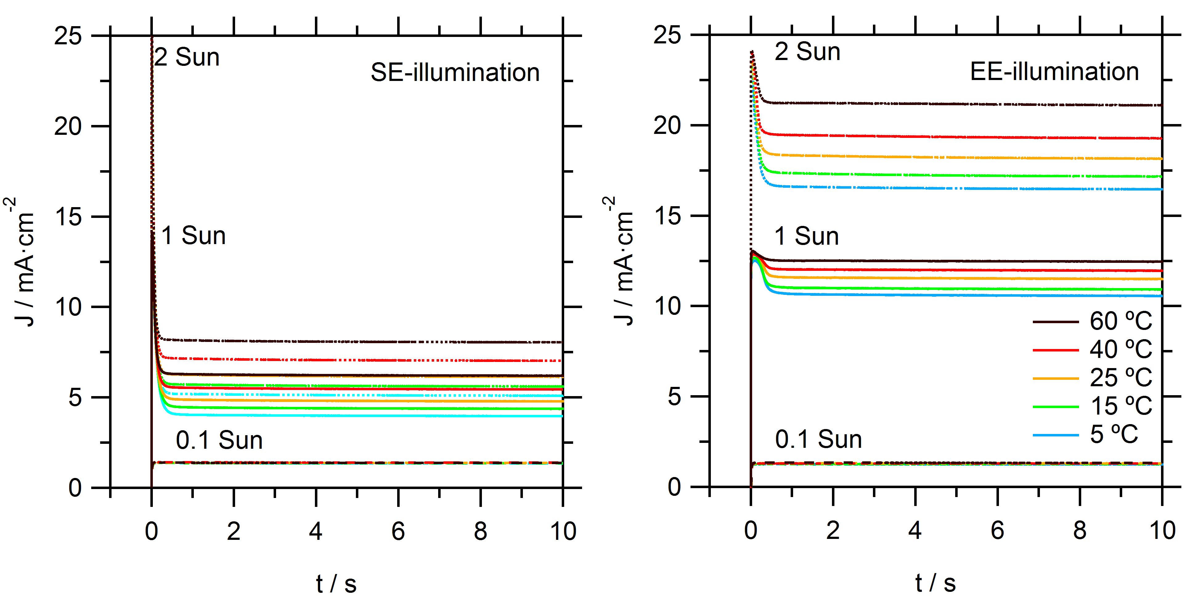
To assess the performance of DSSCs with cobalt tris(bipyridine)/MPN electrolytes, devices are first characterized using J–V curves in simulated sunlight and under a range of temperatures, see Figure 1. For consistency, all data presented is derived from one DSSC device with typical good performance. The illumination direction has a large effect on the performance for these cells. The conventional direction where light enters the cell at the fluorine-doped tin oxide (FTO) substrate of the dye-sensitized film (substrate-electrode or SE-direction) yielded much lower photocurrents than illumination though the counter electrode (electrolyte-electrode or EE-direction). Higher temperatures led to higher photocurrents but slightly lower open-circuit potentials, which is consistent with faster electron-back recombination. Because the photoinjected electron flux in the electrode is identical under all conditions, the differences in photocurrent can be attributed to recombination losses that are a result of mass transport limitations in the electrolyte. Specifically, if insufficient Co(bpy)33+ reached the counter electrode, not all electrons in the photoanode could be extracted, and recombination of electrons to the electrolyte (through both FTO and mesoporous TiO2) had to occur.
From the slope of the J–V curves near the open-circuit potential, it is apparent that there is a significant series resistance in the solar cell under 1 sun illumination. The series resistance increases with decreasing temperature. As will be shown later, a significant part of this series resistance comes from the diffusion resistance in the electrolyte.
On closer inspection, it can be seen in the J–V curves that there is significant hysteresis under SE-illumination and at low temperatures. This effect reduces with EE-illumination and at higher temperatures. It has been recognized that the sweep direction, scan rate, and sampling rate can affect the measured J–V curve for DSSC due to capacitive charging currents. When a negative potential is applied on the mesoporous TiO2 electrode, it displays a high chemical capacity. In the forward scan this can lead to capacitive charging currents resulting in a net current that is a lower value than the steady-state current; in contrast, the capacitive discharge in the reverse scan can lead to a measured current larger than the steady-state current [20]. In the current case, the selected scan settings excluded that capacitive (dis)charge, which is the reason for the observed hysteresis in the J–V curves. Instead, it must be attributed to effects of the mass transport in the electrolyte. Specifically, the concentration gradient of the redox mediator is not in equilibrium at every point of the J–V curve during the measurement. By performing very slow J–V scans, this hysteresis is avoided; however, this is at the cost of very long measurement times. These observations are consistent with trends in mass transport limitation, as will be discussed later. As a result of hysteresis effects, J–V measurements can either over- or under-estimate the true PCE of the DSSC device.
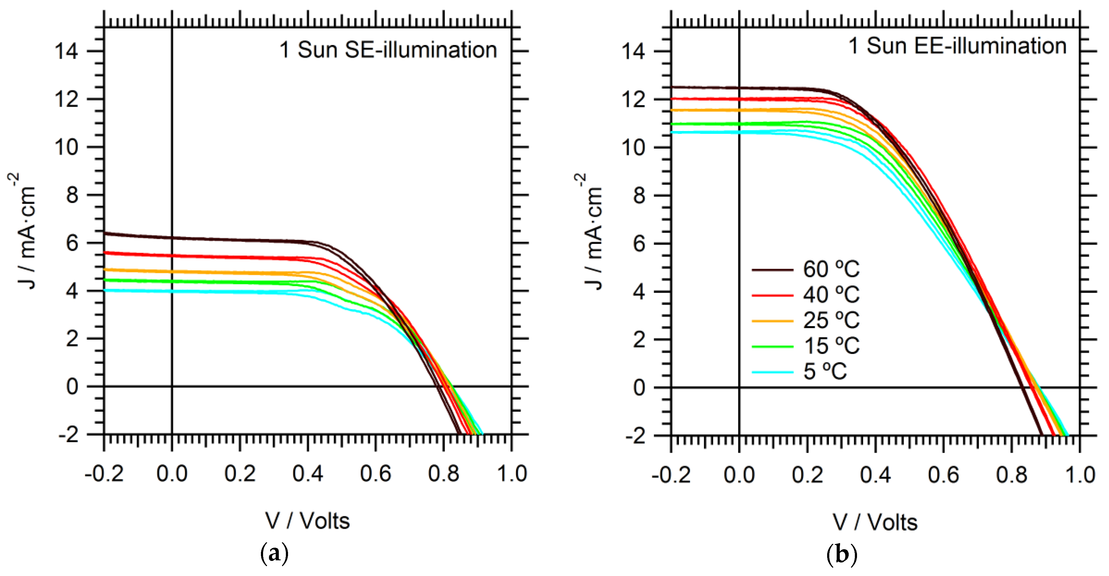
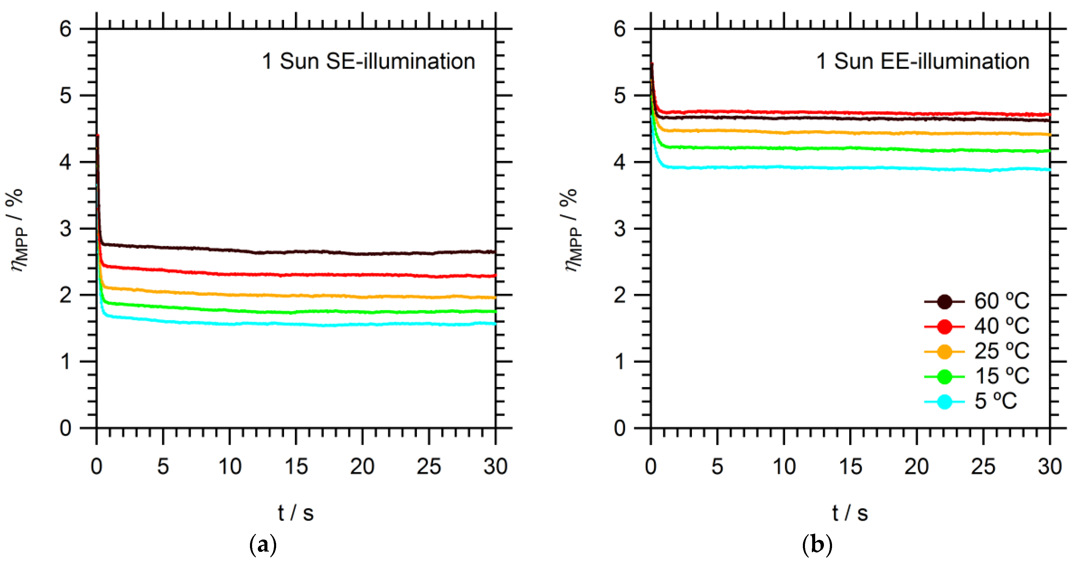
Maximum power point (MPP) tracking is a more accurate and reliable method for determining PCE. Assuming the cell is not prone to drift, the MPP can be determined in a few seconds. The MPP is found to stabilize rapidly (<1 s) under EE-illumination, irrespective of temperature, see Figure 2. On the other hand, under SE-illumination, the MPP continued to drift even after 20 s. This effect is exacerbated at lower temperatures. The long gradual drift in the photocurrent contributed to J–V hysteresis.
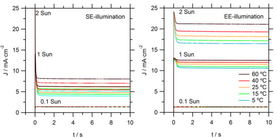
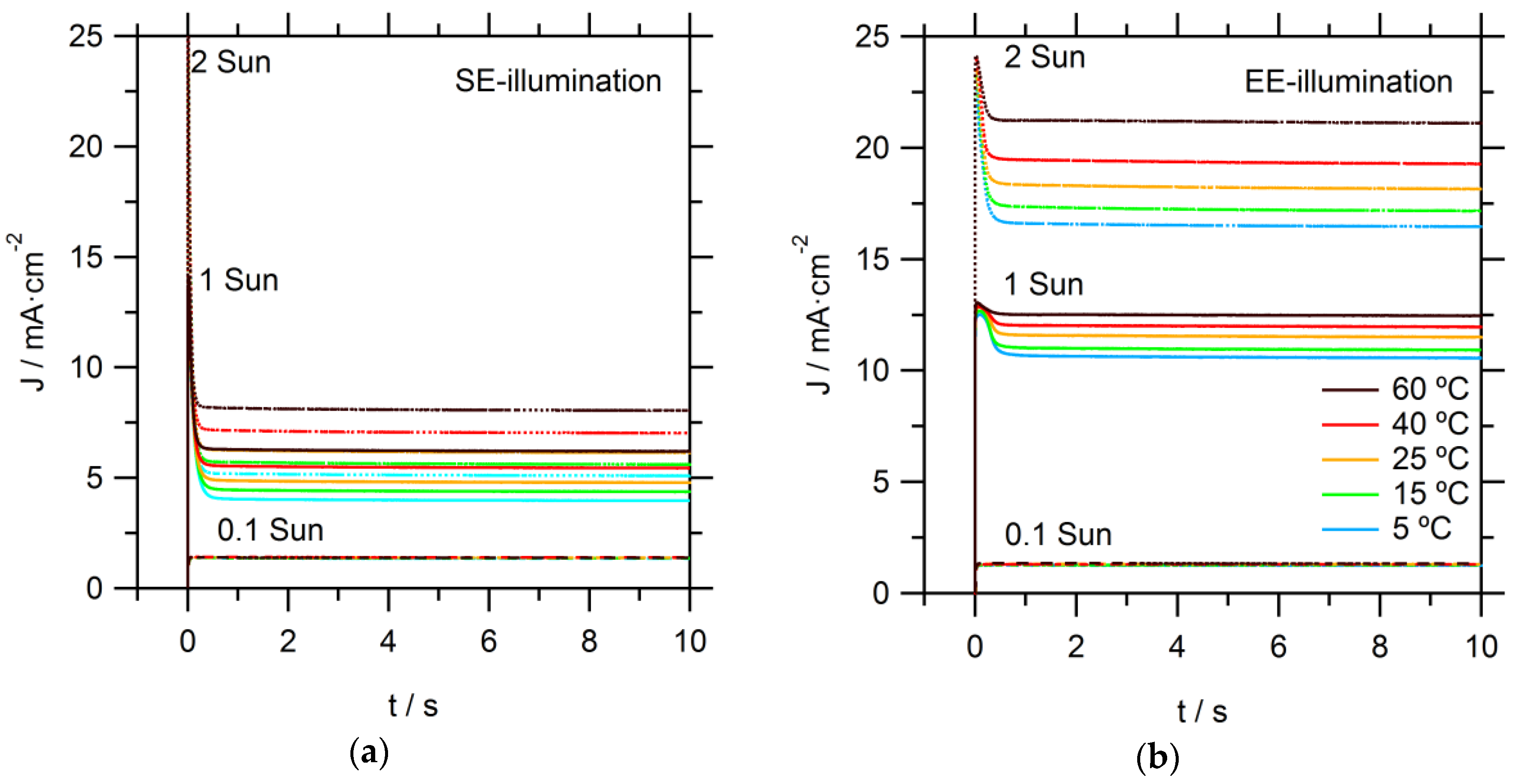
Photocurrent onset transients are recorded to provide more insight on the observed limitations in these DSSCs, as seen in Figure 3. At the relatively low light intensity of 0.1 sun, temperature and illumination direction did not have a significant effect on the recorded photocurrent transients. At the higher intensities (1 and 2 sun), significant spikes are observed: initially, the photocurrent rose rapidly to a high value; it then dropped to stabilize within a second at a significantly lower value. The steady-state photocurrent is much lower for SE than for EE illumination. These effects can be directly attributed to limitations in the mass transport of Co(bpy)33+ to the counter electrode (CE). Directly after the light is switched on, there is sufficient Co(bpy)33+ at the CE; however, its concentration decreased when electrons are collected at the FTO of the working electrode and simultaneous reduction of Co(bpy)33+ at the CE takes place. When the diffusion flux of Co(bpy)33+ to the CE is lower than the flux of electron to the FTO, not all electrons could enter the external circuit and the photocurrent becomes mass transport-limited. Again, it is obvious that EE-illumination conditions allow for much higher current due to a relatively shorter diffusion distance for the Co(bpy)33+. Specifically, under EE-illumination, the average path length for diffusion in the pores of the TiO2 film towards the bulk electrolyte is much shorter.
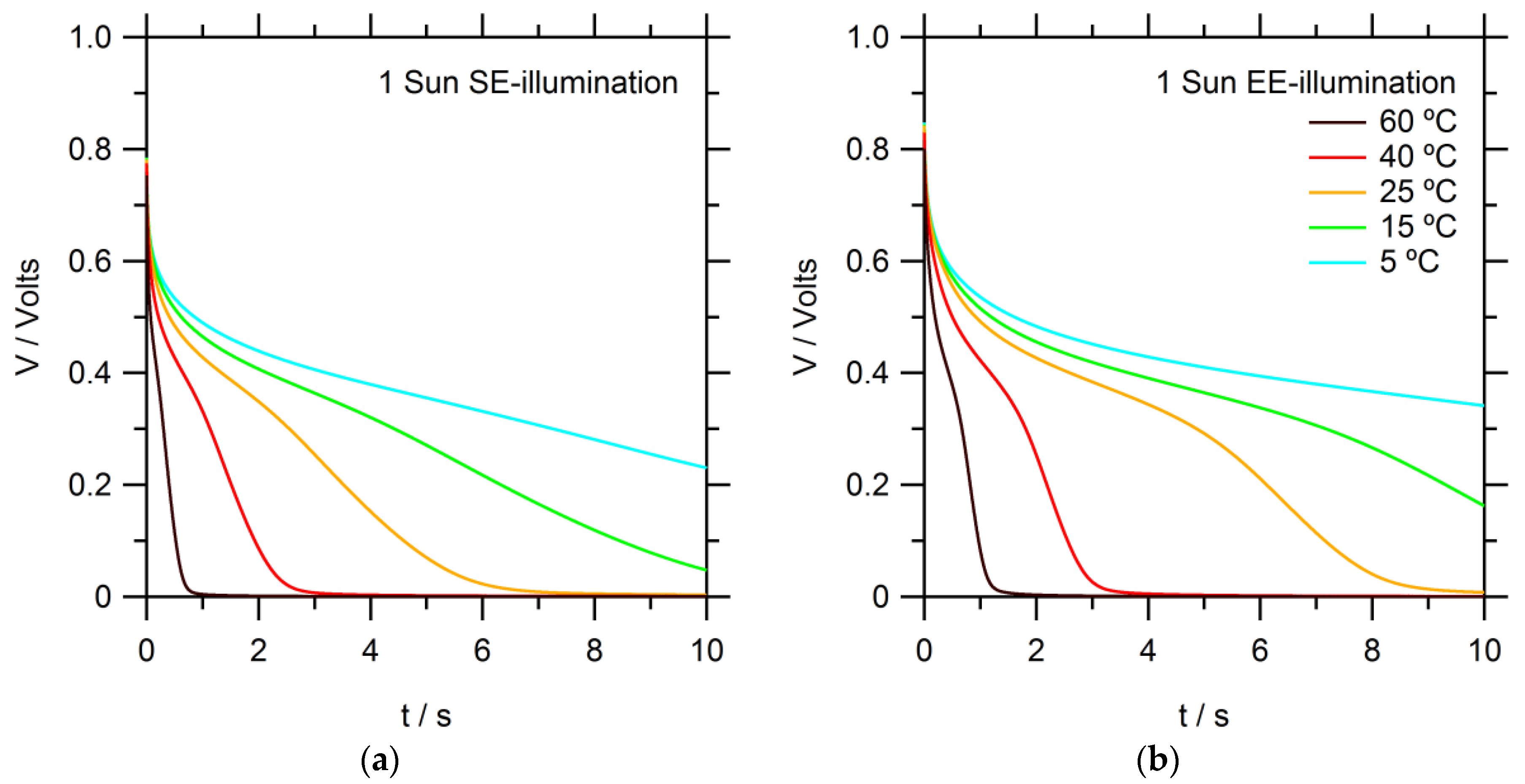
The electron recombination process is studied using open-circuit voltage (VOC) decay measurements in the dark after prior illumination, as seen in Figure 4. Several trends are evident: the voltage decayed faster at higher temperatures, demonstrating faster kinetics for the electron recombination processes. This implies that recombination is an activated process.
Furthermore, VOC decays for SE-illumination are somewhat faster than for EE. This can be explained by the difference in concentration profiles for electrons and Co(bpy)33+ in the mesoporous electrode for SE- and EE-illumination. The concentration of Co(bpy)33+ is higher near the FTO substrate for SE-illumination. The electron lifetime can be calculated from the derivative of the voltage decay transient [22], as follows:
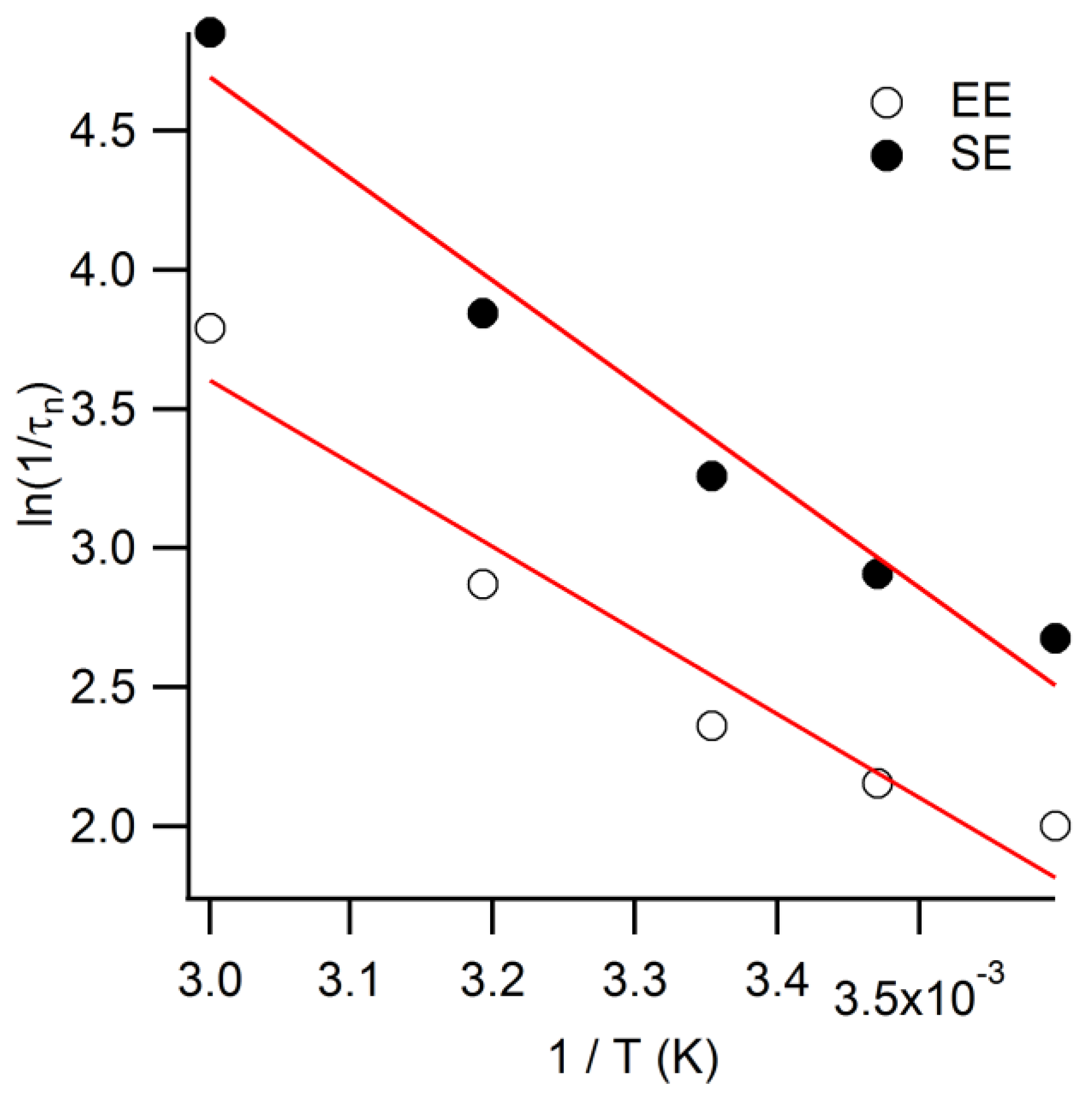
where τn is the electron lifetime for at a given voltage, kB is the Boltzmann constant, e is the elementary charge, T is the absolute temperature, and dVoc/dt is the derivative of the voltage decay transient. When compared at 0.6 V, the electron lifetimes of EE-illuminated counterparts are over two times longer; calculated in Appendix Figure A1 [24], the activation energies corresponded to 0.32 and 0.26 eV for SE- and EE-illumination, respectively.
τn = −(kBT/e)(dVoc/dt)−1,
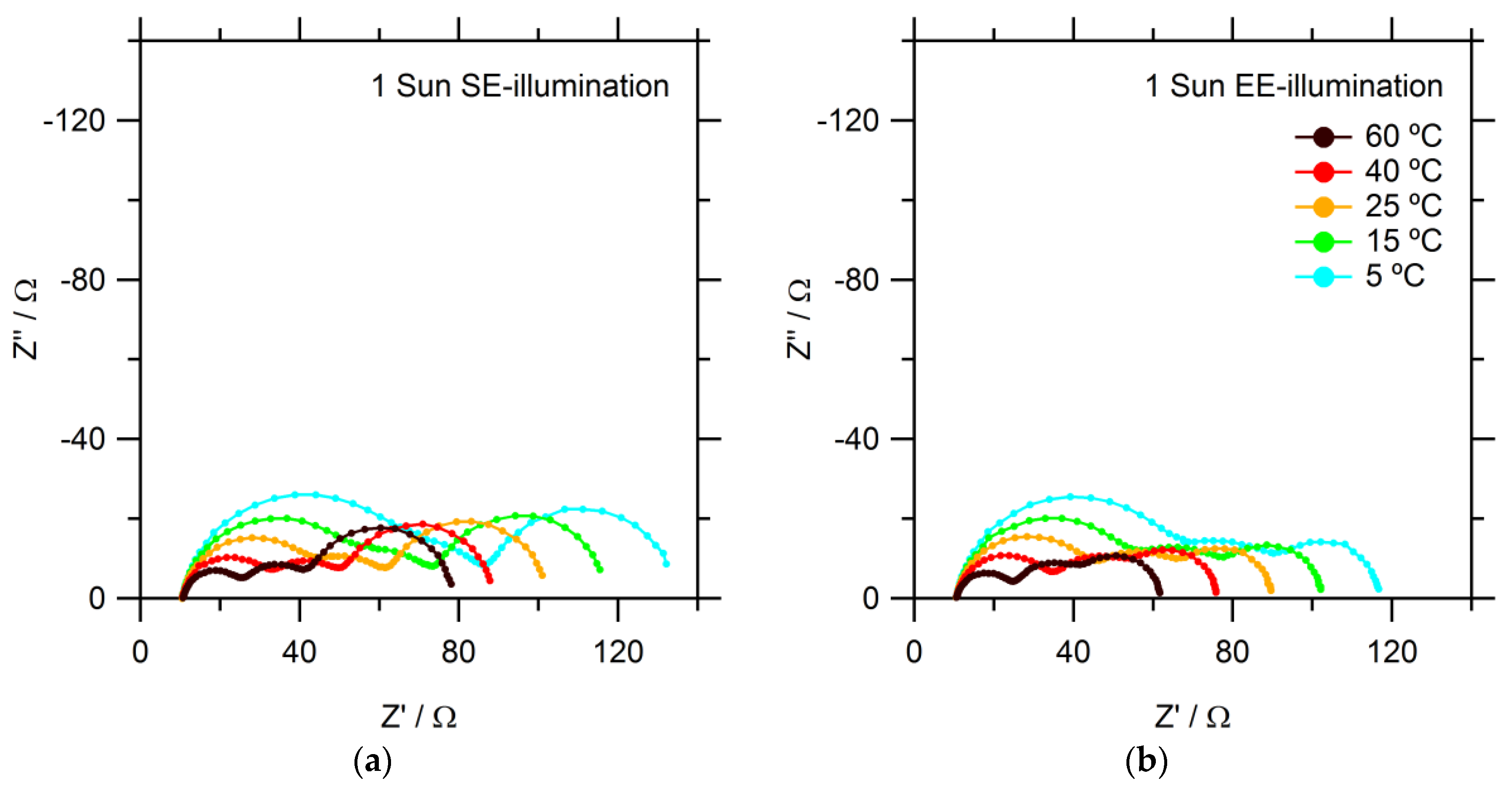
Finally, electrochemical impedance spectroscopy (EIS) measurements are performed. Typical Nyquist plots are shown in Figure 5. Three semicircles can be identified: on the left-hand side, at high frequencies, the response of the counter electrode is seen; at medium frequencies, the electron recombination at the mesoporous TiO2 electrode; finally, at low frequencies, the diffusion of the redox mediator. The charge transfer resistance of the counter electrode increases significantly with lower temperatures for both SE- and EE-illumination. The diffusion resistance is 40% lower for EE-illumination than for SE-illumination at all temperatures. This is consistent with improved overall Co(bpy)33+ diffusion to the CE because less Co(bpy)33+ is generated closer to the SE-side. Ideally, a replacement catalyst material should also exhibit low charge transfer resistance at lower temperatures, since commercial DSSC modules would likely be subjected to such conditions.
From the temperature-dependent EIS data, it is possible to calculate activation energies for several processes. At 25 °C, the charge transfer resistance between the Pt-coated FTO counter electrode and the Co(bpy)3 electrolyte is about 30 Ω, decreasing to 13 Ω at 60 °C. The improved catalytic activity of Pt counter electrodes with higher temperature is consistent with past literature findings [23]. Charge transfer is clearly an activated process, and an activation energy of 0.19 eV is determined for both EE- and SE- illumination. This shows that Pt nanoparticles are thus not very good catalysts for the Co(bpy)33+ + e− = Co(bpy)32+ redox reaction at lower temperatures.
The diffusion resistance is given by:
where R is the gas constant, T is the absolute temperature, l is the diffusion path length, z is the number of charges carried by the mediator (1), F is Faraday’s constant, A is the area, c is the concentration, and D is the diffusion coefficient of the mass transport limiting redox species. Further analysis of the diffusion coefficient (ln(D∝ (RdifT)−1)) vs. 1/T) yields the activation energy for diffusion, which is found to be 0.18 eV for both SE and EE data. The lower value of Rdif for SE data reflects the longer effective diffusion path length through the mesoporous TiO2 electrode when Co(bpy)33+ is generated closer to the FTO substrate of the photoanode.
Rdif = RTl/z2F2AcD,
In summary, dye-sensitized solar cells with Co(bpy)3/TPAA/MPN electrolyte gave good performance under illumination from the counter electrode side. To a large extent, this avoids the diffusion problems of the Co(bpy)33+ species inside the pores of the mesoporous TiO2 because it is generated closer to the bulk electrolyte. Furthermore, this contributed to a higher photocurrent, higher photovoltage, and much more stabilized power output.
3. Materials and Methods
All chemicals were purchased from Sigma Aldrich (Stockholm, Sweden) unless otherwise stated. Fluorine-doped SnO2 (FTO) glass substrates (TEC15, Pilkington, St Helens, Merseyside, UK). TiO2 paste (DSL 30NRD, Dyesol, Queanbeyan, Australia); Cobalt(II/III)tris(2,2′-bipyridyl) ([Co(bpy)3]2+/3+) with tetracyanoborate counter ions, tris(4-methoxyphenyl)amine (TPAA), LEG4 dye (3-(6-(4-[bis(2′,4′-dibutyloxybiphenyl-4-yl) amino-]phenyl)-4,4-dihexyl-cyclopenta-[2,1-b:3,4-b’]dithiophene-2-yl)-2-cyanoacrylic acid), all from Dyenamo (Stockholm, Sweden).
3.1. Device Fabrication
The procedure for device fabrication has been described elsewhere [6,20,26,27]. The electrolyte consisted of 0.2 M Co(bpy)3(B(CN)4)2, 0.1 M Co(bpy)3(B(CN)4)3, 0.1 M LiTFSI and 0.2 M 4-tert-butylpyridine (TBP) in 3-methoxypropionitrile (MPN). The TiO2 photoanode thickness was measured using a profilometer (Veeco Dektak 3, Veeco, Munich, Germany) and determined to be approximately 6.5 μm.
3.2. Device Characterization
All measurements were made using white LED (WLED) illumination (BXRC-27G10K0-L-03, Bridgelux, Fremont, CA, USA). The light intensity of the WLEDs was calibrated to produce the same photocurrent, using a certified reference Si Cell (Fraunhofer ISE, Freiburg, Germany), as measured under AM1.5 solar simulator illumination (Newport, CA, USA), to compare equivalent “sun” intensities in terms of the photon flux density. Temperature dependence measurements were carried out by using a water-cooled breadboard (Thorlabs, MöIndal, Sweden) connected to an immersion circulator (Ecoline RE106, Lauda-Brinkmann, Delran, NJ, USA) and included additional fan-cooling.
Maximum power point (MPP) tracking and J–Vs were acquired using a DAQ (NI6211, National Instruments, Stockholm, Sweden). J–Vs were measured with 5 mV step intervals and a sampling rate of 0.1 V·s−1. Electrochemical impedance spectroscopy (EIS) was measured using an Ivium Compactstat (Ivium technologies, Eindhoven, The Netherlands). Photocurrent turn-on transients and open-circuit voltage decay (OCVD) transients were measured using an in-house built system, which also is previously described elsewhere [26,27].
Author Contributions
Conceptualization, R.J.; Data curation, R.J.; Formal analysis, R.J.; Funding acquisition, G.B.; Investigation, R.J.; Methodology, R.J.; Project administration, R.J.; Resources, R.J.; Software, R.J.; Supervision, G.B.; Validation, Roger Jiang and G.B.; Visualization, R.J. and G.B.; Writing—original draft, R.J. and G.B.; Writing—review & editing, R.J. and G.B.
Funding
This research was funded by the Swedish Research Council [grant number 621-2012-4721], the Swedish Foundation for Strategic Research [grant number RMA15-0130], and the STandUp for Energy program.
Conflicts of Interest
The authors declare no conflict of interest.
Appendix
Figure A1.
Arrhenius plot comparing the inverse of electron lifetime values calculated from OCVD decay transients [24]. SE- and EE-illumination direction compared.
Figure A1.
Arrhenius plot comparing the inverse of electron lifetime values calculated from OCVD decay transients [24]. SE- and EE-illumination direction compared.

References
- O’Regan, B.; Grätzel, M. A low-cost, high-efficiency solar cell based on dye-sensitized colloidal TiO2 films. Nature 1991, 353, 737–740. [Google Scholar] [CrossRef]
- Hagfeldt, A.; Boschloo, G.; Sun, L.; Kloo, L.; Pettersson, H. Dye-Sensitized Solar Cells. Chem. Rev. 2010, 110, 6595–6663. [Google Scholar] [CrossRef] [PubMed]
- Feldt, S.M.; Gibson, E.A.; Gabrielsson, E.; Sun, L.; Boschloo, G.; Hagfeldt, A. Design of Organic Dyes and Cobalt Polypyridine Redox Mediators for High-Efficiency Dye-Sensitized Solar Cells. J. Am. Chem. Soc. 2010, 132, 16714–16724. [Google Scholar] [CrossRef] [PubMed]
- Kakiage, K.; Aoyama, Y.; Yano, T.; Oya, K.; Fujisawa, J.; Hanaya, M. Highly-efficient dye-sensitized solar cells with collaborative sensitization by Silyl-anchor and Carboxy-anchor dyes. Chem. Commun. 2015, 51, 15894–15897. [Google Scholar] [CrossRef] [PubMed]
- Zhou, D.; Yu, Q.; Cai, N.; Bai, Y.; Wang, Y.; Wang, P. Efficient organic dye-sensitized thin-film solar cells based on the tris(1,10-phenanthroline)cobalt(II/III) redox shuttle. Energy Environ. Sci. 2011, 4, 2030. [Google Scholar] [CrossRef]
- Hao, Y.; Yang, W.; Zhang, L.; Jiang, R.; Mijangos, E.; Saygili, Y.; Hammarström, L.; Hagfeldt, A.; Boschloo, G. A small electron donor in cobalt complex electrolyte significantly improves efficiency in dye-sensitized solar cells. Nat. Commun. 2016, 7, 13934. [Google Scholar] [CrossRef] [PubMed] [Green Version]
- Wang, P.; Zakeeruddin, S.M.; Moser, J.-E.; Grätzel, M. A New Ionic Liquid Electrolyte Enhances the Conversion Efficiency of Dye-Sensitized Solar Cells. J. Phys. Chem. B 2003, 107, 13280–13285. [Google Scholar] [CrossRef] [Green Version]
- Wang, P.; Zakeeruddin, S.M.; Comte, P.; Exnar, I.; Grätzel, M. Gelation of ionic liquid-based electrolytes with silica nanoparticles for quasi-solid-state dye-sensitized solar cells. J. Am. Chem. Soc. 2003, 125, 1166–1167. [Google Scholar] [CrossRef] [PubMed]
- Wang, P.; Zakeeruddin, S.M.; Moser, J.E.; Nazeeruddin, M.K.; Sekiguchi, T.; Grätzel, M. A stable quasi-solid-state dye-sensitized solar cell with an amphiphilic ruthenium sensitizer and polymer gel electrolyte. Nat. Mater. 2003, 2, 402–407. [Google Scholar] [CrossRef] [PubMed]
- Bella, F.; Gerbaldi, C.; Barolo, C.; Grätzel, M. Aqueous dye-sensitized solar cells. Chem. Soc. Rev. 2015, 44, 3431–3473. [Google Scholar] [CrossRef] [PubMed] [Green Version]
- Wang, P.; Klein, C.; Humphry-Baker, R.; Zakeeruddin, S.M.; Grätzel, M. Stable ≥8% efficient nanocrystalline dye-sensitized solar cell based on an electrolyte of low volatility. Appl. Phys. Lett. 2005, 86, 123508. [Google Scholar] [CrossRef]
- Cabral, D.; Howlett, P.C.; Pringle, J.M.; Zhang, X.; MacFarlane, D. Electrochemistry of tris(2,2′-bipyridyl) cobalt(II) in ionic liquids and aprotic molecular solvents on glassy carbon and platinum electrodes. Electrochim. Acta 2015, 180, 419–426. [Google Scholar] [CrossRef]
- Nelson, J.J.; Amick, T.J.; Elliott, C.M. Mass Transport of Polypyridyl Cobalt Complexes in Dye-Sensitized Solar Cells with Mesoporous TiO2 Photoanodes. J. Phys. Chem. C 2008, 112, 18255–18263. [Google Scholar] [CrossRef]
- Xiang, W.; Huang, W.; Bach, U.; Spiccia, L. Stable high efficiency dye-sensitized solar cells based on a cobalt polymer gel electrolyte. Chem. Commun. 2013, 49, 8997–8999. [Google Scholar] [CrossRef] [PubMed]
- Bella, F.; Vlachopoulos, N.; Nonomura, K.; Zakeeruddin, S.M.; Grätzel, M.; Gerbaldi, C.; Hagfeldt, A. Direct light-induced polymerization of cobalt-based redox shuttles: An ultrafast way towards stable dye-sensitized solar cells. Chem. Commun. 2015, 51, 16308–16311. [Google Scholar] [CrossRef] [PubMed]
- Xu, D.; Zhang, H.; Chen, X.; Yan, F. Imidazolium functionalized cobalt tris(bipyridyl) complex redox shuttles for high efficiency ionic liquid electrolyte dye-sensitized solar cells. J. Mater. Chem. A 2013, 1, 11933–11941. [Google Scholar] [CrossRef]
- Law, C.; Moudam, O.; Villarroya-Lidon, S.; O’Regan, B. Managing wetting behavior and collection efficiency in photoelectrochemical devices based on water electrolytes; improvement in efficiency of water/iodide dye sensitised cells to 4%. J. Mater. Chem. 2012, 22, 23387–23394. [Google Scholar] [CrossRef]
- Xiang, W.; Huang, F.; Cheng, Y.; Bach, U.; Spiccia, L. Aqueous dye-sensitized solar cell electrolytes based on the cobalt(II)/(III) tris(bipyridine) redox couple. Energy Environ. Sci. 2013, 6, 121–127. [Google Scholar] [CrossRef]
- Ellis, H.; Jiang, R.; Ye, S.; Hagfeldt, A.; Boschloo, G. Development of high efficiency 100% aqueous cobalt electrolyte dye-sensitised solar cells. Phys. Chem. Chem. Phys. 2016, 18, 8419–8427. [Google Scholar] [CrossRef] [PubMed]
- Jiang, R.; Boschloo, G. The Impact of Non-Uniform Photogeneration on Mass Transport in Dye-Sensitised Solar Cells. J. Mater. Chem. A 2018, 6, 10264–10276. [Google Scholar] [CrossRef]
- Koide, N.; Han, L. Measuring methods of cell performance of dye-sensitized solar cells. Rev. Sci. Instrum. 2004, 75, 2828–2831. [Google Scholar] [CrossRef]
- Yang, X.; Yanagida, M.; Han, L. Reliable evaluation of dye-sensitized solar cells. Energy Environ. Sci. 2013, 6, 54–66. [Google Scholar] [CrossRef]
- Takagi, K.; Magaino, S.; Saito, H.; Aoki, T.; Aoki, D. Measurements and evaluation of dye-sensitized solar cell performance. J. Photochem. Photobiol. C Photochem. Rev. 2013, 14, 1–12. [Google Scholar] [CrossRef]
- Zaban, A.; Greenshtein, M.; Bisquert, J. Determination of the Electron Lifetime in Nanocrystalline Dye Solar Cells by Open-Circuit Voltage Decay Measurements. ChemPhysChem 2003, 4, 859–864. [Google Scholar] [CrossRef] [PubMed]
- Petrocco, A.; Liberatore, M.; Di Carlo, A.; Reale, A.; Brown, T.M.; Decker, F. Thermal activation of mass transport and charge transfer at Pt in the I3−/I− electrolyte of a dye-sensitized solar cell. Phys. Chem. Chem. Phys. 2010, 12, 10786–10792. [Google Scholar] [CrossRef] [PubMed]
- Jiang, R.; Anderson, A.; Barnes, P.R.F.; Xiaoe, L.; Law, C.; O’Regan, B.C. 2000 hours photostability testing of dye sensitised solar cells using a cobalt bipyridine electrolyte. J. Mater. Chem. A 2014, 2, 4751–4757. [Google Scholar] [CrossRef]
- García-Rodríguez, R.; Jiang, R.; Canto-Aguilar, E.J.; Oskam, G.; Boschloo, G. Improving the mass transport of copper-complex redox mediators in dye-sensitized solar cells by reducing the inter-electrode distance. Phys. Chem. Chem. Phys. 2017, 19, 32132–32142. [Google Scholar] [CrossRef] [PubMed]
Figure 1.
J–V curves of a DSSC with Co(bpy)3/TPAA/MPN electrolyte for (a) SE- and (b) EE-illumination. The film thickness is 6.5 μm.
Figure 1.
J–V curves of a DSSC with Co(bpy)3/TPAA/MPN electrolyte for (a) SE- and (b) EE-illumination. The film thickness is 6.5 μm.

Figure 2.
Maximum power point tracking of a DSSC with Co(bpy)3/TPAA/MPN electrolyte under (a) SE- and (b) EE-illumination and at different temperatures.
Figure 2.
Maximum power point tracking of a DSSC with Co(bpy)3/TPAA/MPN electrolyte under (a) SE- and (b) EE-illumination and at different temperatures.

Figure 3.
Photocurrent onset transients of a DSSC with Co(bpy)3/TPAA/MPN electrolyte for (a) SE- and (b) EE-illumination.
Figure 3.
Photocurrent onset transients of a DSSC with Co(bpy)3/TPAA/MPN electrolyte for (a) SE- and (b) EE-illumination.

Figure 4.
Open-circuit voltage decay of a DSSC with Co(bpy)3/TPAA/MPN electrolyte in the dark after an illumination period of 10 s at 1 sun, comparing (a) SE- and (b) EE- illumination.
Figure 4.
Open-circuit voltage decay of a DSSC with Co(bpy)3/TPAA/MPN electrolyte in the dark after an illumination period of 10 s at 1 sun, comparing (a) SE- and (b) EE- illumination.

Figure 5.
Impedance spectra of a DSSC with Co(bpy)3/TPAA/MPN electrolyte at open circuit potential under 1 sun illumination for (a) SE- and (b) EE- illumination.
Figure 5.
Impedance spectra of a DSSC with Co(bpy)3/TPAA/MPN electrolyte at open circuit potential under 1 sun illumination for (a) SE- and (b) EE- illumination.

© 2018 by the authors. Licensee MDPI, Basel, Switzerland. This article is an open access article distributed under the terms and conditions of the Creative Commons Attribution (CC BY) license (http://creativecommons.org/licenses/by/4.0/).
Share and Cite
MDPI and ACS Style
Jiang, R.; Boschloo, G. The Effect of Illumination Direction and Temperature on Dye-Sensitized Solar Cells with Viscous Cobalt Complex-Based Electrolytes. Inorganics 2018, 6, 60. https://doi.org/10.3390/inorganics6020060
AMA Style
Jiang R, Boschloo G. The Effect of Illumination Direction and Temperature on Dye-Sensitized Solar Cells with Viscous Cobalt Complex-Based Electrolytes. Inorganics. 2018; 6(2):60. https://doi.org/10.3390/inorganics6020060
Chicago/Turabian StyleJiang, Roger, and Gerrit Boschloo. 2018. "The Effect of Illumination Direction and Temperature on Dye-Sensitized Solar Cells with Viscous Cobalt Complex-Based Electrolytes" Inorganics 6, no. 2: 60. https://doi.org/10.3390/inorganics6020060
Note that from the first issue of 2016, this journal uses article numbers instead of page numbers. See further details here.