1. Introduction
Fuel processing has long been studied for the decentralized production of H
2 from fossil and bio fuels for the feeding of H
2-fuel cells. The development of a network of hydrogen filling stations realized with small-scale fuel processor units fed with hydrocarbon fuels has been conceived as a strategy to take advantage of the existing fuel infrastructure and favor a smooth transition from a fossil-based to a future renewable-based hydrogen economy [
1,
2,
3,
4,
5]. In particular, small scale fuel processors have been studied for the auxiliary power units (APUs) which supply on-board energy for electrical uses other the vehicle motion, and for micro-combined heat and power units (micro-CHPs), the extension of the concept of cogeneration to small-scale applications [
6,
7]. Indeed, the penetration of advanced and efficient energy systems, based on fuel cells, was shown to have the potential for substantially contributing to the decarbonization of the energy system [
8], in line with the EU Energy Roadmap target for 2050 [
9].
Several R and D initiatives in Europe have driven the development and commercialization of APUs and micro-CHPs and have been recently reviewed by Specchia [
10].
In this paper, we report the design of a steam reforming unit as part of the development of a 10 kW combined heat and power system for residential applications, within the MICROGEN30 project funded by the Industria 2015 program. Indeed, micro-CHP systems may fit well with the energy demand of buildings, and the application of micro-CHP to residential heat and power supply has grown among stakeholders, including energy companies, gas distributors, independent power producers and end users [
7,
11].
A key issue related to micro-CHP systems is the reliability; the commercialization requires on one side, high efficiency and low environmental impact, and on the other side, stable, robust and easy-to-handle operability. This involves all the CHP components, and among them, the catalytic stages of the fuel processor, which typically consists of a series of steam reforming, water gas shift and final CO-elimination units.
Thus, the general objective of developing a small scale fuel processor through the intensification of the train of catalytic units cannot be decoupled from the verification of the catalyst stability during time on stream and of the robustness of the reactor design against possible deactivation processes [
12]. In this work, the development of the steam reforming unit is addressed by combining experimental investigations on the process kinetics and the catalyst stability and a modelling study, aiming at a conservative sizing of the reactor such that stability and robustness to perturbations are guaranteed.
The general objective of intensification of catalytic reactors calls for: (a) a reduction of the reactors volumes; (b) an improvement of the response dynamics; (c) an enhancement of heat and mass transfer through proper design of materials and reactors; (d) the optimization of heat recovery in order to maximize the process efficiency [
13]. Preliminary investigations within the research project and previous studies from the literature on catalysts (e.g., mixed oxides vs. noble metal based catalysts) [
14,
15], reactor designs (packed bed of pellets vs coated monoliths or foams) [
16,
17,
18,
19], fuel processor solution and layout (partial oxidations vs. steam reforming, H
2 purification stages vs. membrane reactors) [
19,
20,
21,
22,
23,
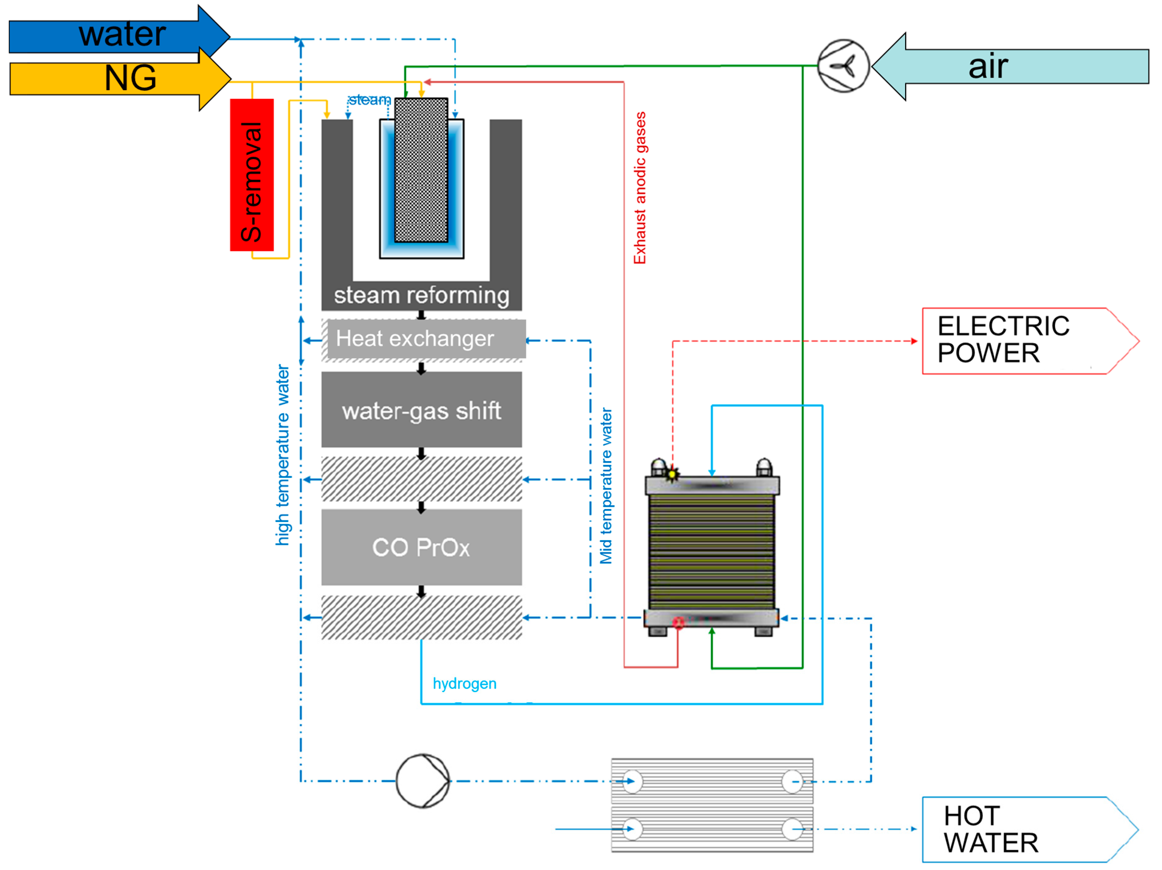
24], have led to the configuration schematically represented in
Figure 1.
Natural gas and H2O are fed to a steam reformer unit, heated by the burner which is co-fueled by the proton-exchanged membrane (PEM) stack tail gas. The syngas is treated in a series of units including high temperature and low temperature WGS reactors and a final CO-Prox unit for CO conversion down to the few ppm levels. Heat recovery stages provide the ‘Hot Water’ exit and the PEM-stack provides the ‘Power Exit’.
Concerning the steam reforming unit, the heart of the fuel processor, key design solutions included: (a) the use of a commercial precious metal catalyst, in view of future commercialization; (b) the design of an annular steam reforming reactor, packed with the catalyst particles diluted with SiC beads, as highly conductive medium; (c) a proprietary design of the burner developed by ICI-Caldaie.
In the following, we report the results of a lab-scale investigation on the activity and stability of the catalyst under conditions representative of the real operation and a modelling analysis on the expected performance of the SR unit of the CHP-prototype.
2. Experimental
A commercial catalyst was used for the investigation, provided in the form of small spheres with the average diameter of 2 mm. The catalyst was tested in two different rigs, one for steam reforming kinetic tests with diluted CH4/H2O/N2 feed mixtures, one for long term steam reforming tests with concentrated CH4/H2O feeds.
Kinetic testing—The rig for kinetic testing consisted several ¼ inches stainless-steel lines connected to high pressure cylinders and equipped with P-reducers, filters, P-gauges, smart Brooks mass flow controllers for the delivery of gases (CH4, N2, O2). H2O was fed by saturating a N2 stream in a H2O-saturator kept at the desired temperature (varying in between 45 and 60 °C, depending on the feed conditions) by a heating bath.
A quartz reactor with an inner diameter of 16 mm was packed with the catalyst beads, supported by a bed of pressed quartz wool. A stainless steel capillary was inserted along the reactor axis to host a sliding K-thermocouple. The reactor was externally heated by a Carbolite oven. All lines upstream and downstream from the reactor were electrically heated at 120 °C to avoid H2O condensation.
The wet product stream was analyzed by a SRA R-3000 microGC equipped with a MolSieve column using Ar as carrier gas (for the separation of H2, N2, CO, CH4) and a Poraplot Colum using He as carrier (for the separation of CO2 and H2O), both connected to TCDs.
The rig was first used to identify the main kinetic dependences of steam reforming over the commercial catalyst, in order to (i) develop a rate expression, suitable for modeling applications, and (ii) estimate the intrinsic rate of the fresh catalyst. At this scope, steam reforming experiments on the fresh catalyst were performed at variable space velocities from 5000 to 100,000 Nl/kgcat/h and increasing temperature from 300 to 850 °C; the effect of reactant concentration was investigated by varying CH4 (from 0.5% to 3.5%) and H2O concentration (0.5–2.0%).
Within this wide operating range, central operating conditions were identified as standard reference conditions: 0.5% CH4, steam/C = 3.5, GHSV = 75,000 Nl/kgcat/h. These conditions were periodically tested to verify the stability of the catalyst; notably, although long-term tests under concentrated CH4/steam mixtures were accompanied by a loss of activity, no significant change of performance was observed during the kinetic investigation, likely due to the highly diluted feed conditions. Still, the catalyst load was periodically changed in the reactor.
In a later phase of the work, the same reference conditions were adopted to run kinetically informative steam reforming tests over the samples unloaded from the long-term ageing runs, thus measuring the evolution of the intrinsic activity from the initial value. Any aged sample was subject to one single run.
All the activity tests (both with fresh and aged samples) were performed by setting the feed mixtures and changing step-wise the oven temperature from 300 to 850 °C. After each step change, steady state conditions of the oven-reactor assembly were reached within few minutes; multiple analyses were then repeated and averaged for the measure of the product stream composition. C-balances were checked and closed within an error of 3%.
Temperature-programmed oxidation (TPO) experiments were also performed by using the same rig, to verify the deposition of C during the steam reforming ageing tests. The analyses were performed by first heating the reactor in a N2 stream up to 150 °C, then switching N2 with air and further increasing temperature up to 650 °C.
Equilibrium calculations—Thermodynamic equilibrium calculations were performed at constant temperature and pressure by a MATLAB® code that minimizes the Gibbs function, where the gas phase was assumed a mixture of ideal gases. Ideality for all the gaseous species (CH4, N2, CO, CO2, H2 and H2O) was assumed. Formation of solid carbon (graphitic) was also included in the calculations.
Long term steam reforming testing—More representative operating conditions were realized in a second rig, equipped with stainless-steel lines and Bronkhorst mass flow controllers for the feeding of CH
4 and liquid H
2O and designed to test a larger sample of catalyst (3.5 g), typically mixed with SiC particles of the same diameter, with a SiC to catalyst weight ratio of 4 to minimize radial and axial temperature gradients.
Figure S1 in the
Supplementary Material reports a schematic drawing of the reactor.
The reactor consists of a stainless-steel tube with inner diameter of 29.5 mm and a total height of 500 mm. It is equipped with flanges; the upper flange allows for the separate feeding (not shown in
Figure S1) of the two reactants (gaseous CH
4 and liquid H
2O) as well as the loading and unloading of the reactor, the bottom flange allows for the separate collection of the dry product stream and the condensed water. At the bottom side of the reactor, in fact, this is equipped with a jacket for the circulation of a cooling fluid, in order to obtain the condensation of H
2O; the H
2O-free gaseous products are delivered to the GC analysis and vent, while the condensed water is collected in a drum equipped with an on-off discharge valve actuated by a level switch.
A perforated SS disk is soldered at mid height of the reactor and serves as the support for the catalyst bed; two TC-wells are then welded to it on the bottom side and allow for the measurement of the outlet bed temperature in the axial and mid-radius positions of the reactor. Several plates with small holes in different radial locations are then placed in between the inlet flange and the catalyst bed to allow for the mixing of the reactants and the even flow distribution across the reactor section. All void volumes were filled with quartz wool at this scope.
The upper part of reactor is externally heated by an annular oven which guarantees the vaporization of water and the heating of the catalyst bed at the desired temperature.
The analysis of the gaseous mixture was performed by sampling it and injecting into a microGC with the same configuration as above illustrated for the lab-scale rig.
3. Modelling of the Full-Scale Steam Reforming Reactor
A 2D pseudo-homogeneous model of the annular steam reformer of the full scale prototype was developed; it consists of the differential mass balances for the reacting species (CH
4, H
2O, CO, CO
2, H
2) and the differential enthalpy balance, across the annular volume element with radius
r, width
dr and length
dz. The differential equations are detailed in
Appendix A, together with initial and boundary conditions. They assume that the inner surface of the reactor is heated being q(
z) the assigned thermal load per unit length of the reactor. The outer surface was treated as an adiabatic wall.
Concerning the transport parameters, the effective radial thermal conductivity of the packed bed
and the heat transfer coefficient at the wall
have been estimated according to the correlation proposed by Specchia et al. [
25]. The conductivity of solid particles was assumed equal to 50 W/(mK) [
26]. The axial thermal conductivity
was estimated by accounting for the conductive and the convective contributions:
where the conductive contribution was estimated based on the correlation proposed by Bauer, Zehner and Schlunder (BTS model) [
27], while the convective contribution was estimated by assuming that the axial Peclet number is equal to 2 [
28].
Axial and radial dispersion coefficients were also estimated by assuming that the axial and radial mass Peclet number are equal to 2 and 10, respectively [
28].
Concerning the kinetic scheme, two reactions were accounted for, namely the steam reforming reaction with stoichiometry:
and the water gas shift reaction:
The kinetics of the two chemical processes were described based on the results of previous investigations from our laboratory. For the steam reforming reaction, we adopted the rate expression developed by Donazzi et al. [
29,
30].
This expression accounts for a first order dependence of the reaction rate from the concentration of CH4, a zero order dependence on water and the inhibiting effect from O2 adsorption (which is relevant in the case of autothermal reforming or partial oxidation processes) and CO adsorption; the term that multiplies the rate in (4) is a step function varying from unity to zero when the partial pressure of water becomes below 10−6 thus forcing the rate function to zero in the absence of water. The term accounts instead for the reversibility of the reaction; is in fact defined as the ratio between the reaction quotient () and the equilibrium constant . Thus the term approaches zero when the reaction approaches the chemical equilibrium.
Although developed for a home-made 2% by weight Rh/Al
2O
3 catalyst, the rate expression (4) described is coherent with the main kinetic dependences identified for the present catalyst. Experiments at varying concentrations of CH
4 (while keeping constant the concentration of H
2O) showed that the reaction intrinsic kinetics have an overall reaction order below unity, which suggests the relevance of adsorption phenomena from reactants and products especially at the lowest temperatures (results are reported in the
Supplementary Material, Figure S2). Experiments at varying H
2O concentration confirmed the substantial independence of the reaction rate from the concentration of the co-reactant (
Figure S3). Similar kinetic dependences (first order dependence on CH
4 concentration and independence from the concentration of the co-reactant H
2O) were found in the literature for Rh, Pt and Ni, although with no effects from adsorption phenomena [
31,
32].
The kinetic parameters of the original rate expression by Donazzi et al. [
29] were kept unchanged except for the intrinsic constant
which was adapted to the activity tests of the present catalyst; at this scope the lab-scale reactor was modelled as a pseudo-homogeneous plug flow reactor [
28]. The model fitting resulted in an intrinsic parameter
reduced by a factor of 0.25 with respect to the original parameter estimated in [
29].
Concerning the water gas shift reaction, the rate expression proposed in the same study was herein adopted.
In this case, no adjustment was done, since the reaction is expected to be under thermodynamic control at the operating conditions of the fuel processor. Since the reaction rate has a zeroth order dependence on CO partial pressure (coherently with the kinetics of WGS on several metal catalysts [
33]), then it is corrected by the function
that reduces to zero when
approaches zero.
4. Results
4.1. Performance of the Fresh Catalyst
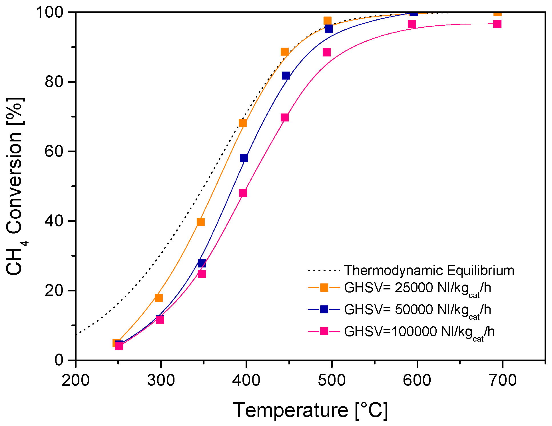
Figure 2 reports the results of SR tests over the fresh catalysts with highly diluted feed streams and varying space velocity, expressed in terms of measured CH
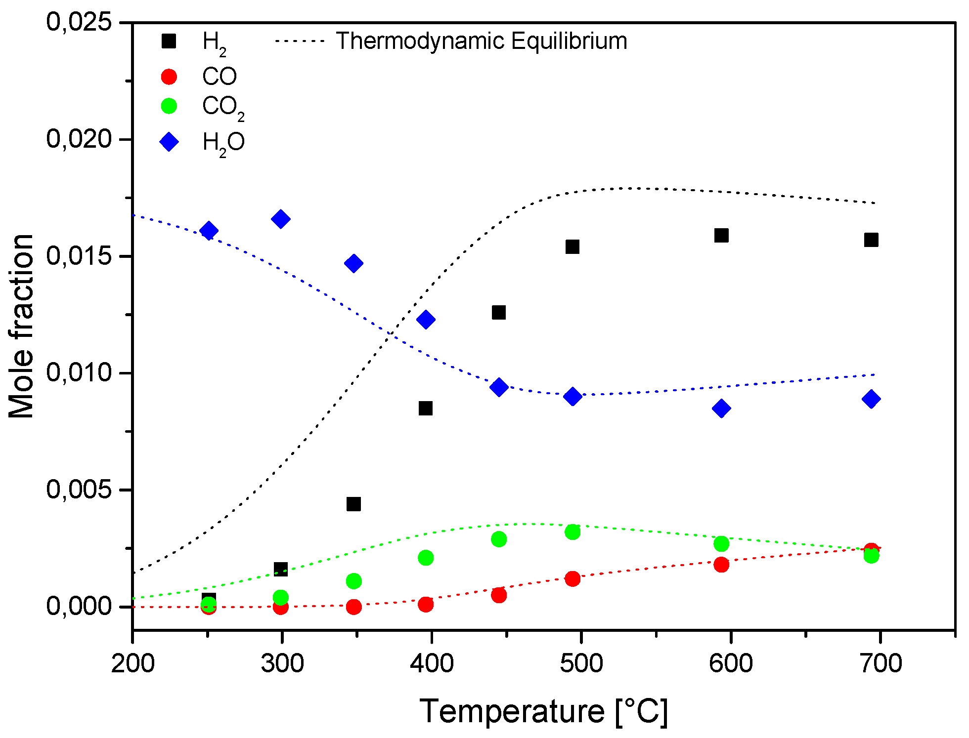
4 conversion, while
Figure 3 details the evolution of the product distribution at increasing temperature at the highest space velocity investigated. The large dilution of the feed stream (CH
4 concentration = 0.5%) allowed to minimize any temperature gradient across the catalyst bed and increasingly high space velocities were tested to identify conditions where (under such diluted feed conditions) the measured performance was significantly far from the thermodynamic control. Equilibrium conversion and concentrations are also reported in dotted lines for comparison. The commercial catalyst was highly active and at the space velocity of 25,000 Nl/kg
cat/h the conversion of CH
4 approached closely the equilibrium at temperatures above 400 °C. The thermodynamic control weakened only at values of space velocity (referred to the entire catalyst volume) higher than 50,000 Nl/kg
cat/h.
The process was characterized by the progressive formation H
2, CO and CO
2. The concentration of the latter species passed through a maximum at increasing temperature due to thermodynamics of WGS. The H
2/CO ratio decreased with temperature and it approached a value of six at the highest temperatures (
Figure S4 in the
Supplemetary Material).
Concerning the effect of space velocity, on the one side, it was estimated that a value of space velocity well below 25,000 Nl/kgcat/h is needed to reach a close approach to the thermodynamic conditions in the fuel processor (additional experiments at largely decreasing space velocity showed that equilibrium conversions were attained above 500 °C when operating below 5000 Nl/kgcat/h); on the other side, the reference condition of 75,000 Nl/kgcat/h was selected as the preferred value to test the catalysts far from thermodynamic constraints and, thus, measure the changes of the catalyst activity after long-term SR tests in the pilot scale reactor.
4.2. Catalyst Ageing
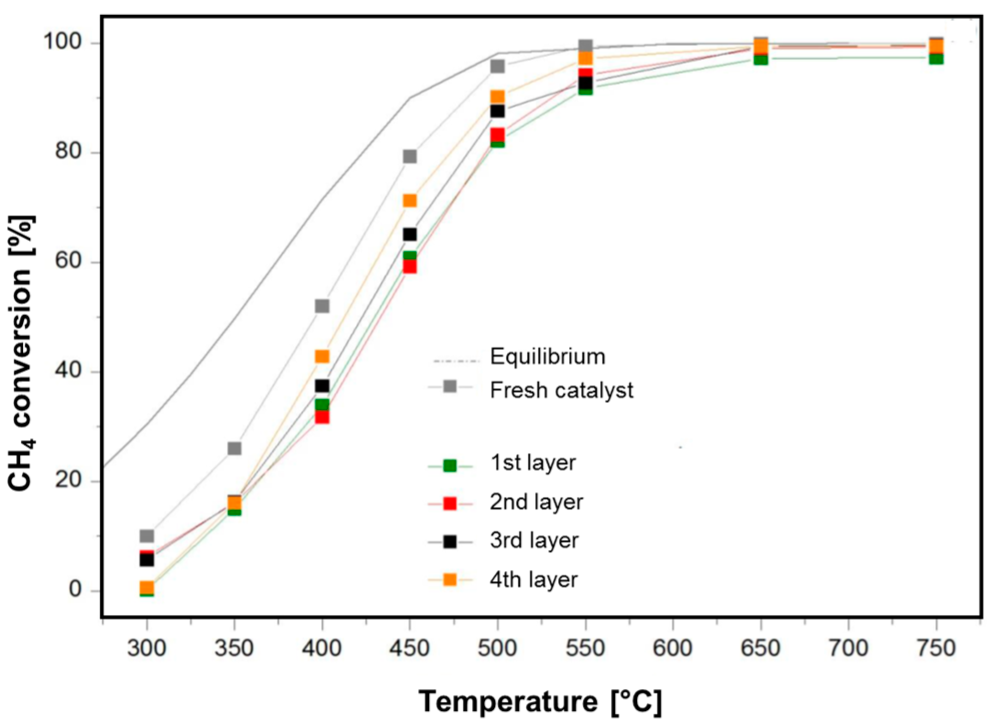
Long term tests were performed in the pilot scale rig with durations of 163, 336 and 720 h, respectively. After each test, the catalyst was unloaded from the reactor and sampled according to the axial coordinate of the bed. Four successive layers were collected, qualitatively corresponding to successive fourths of the bed. The samples were tested at the lab-scale rig under diluted feeds and the measured performances were compared with those of the fresh catalyst.
An example is given in
Figure 4, which reports the analyses performed over the catalyst unloaded after 163 h on stream. The Figure shows the comparison between the conversion curves of the fresh (grey) catalyst and the conversion curves of the four layers; it is evident that the catalyst located in the entering layer of the bed was mostly deactivated, while at increasing depth of the catalyst along the axial coordinate the loss of activity was milder.
Data were quantitatively analyzed by adapting a pseudo-homogeneous plug flow model of the reactor incorporating the kinetics for steam reforming and water gas shift, where only the kinetic constant of steam reforming was left as an adaptive parameter.
By obtaining a ratio of the estimated activity constant of the various samples to that of the fresh catalyst, we estimated the degree of deactivation. In particular we defined the following parameter:
representative of the ratio between measured activity of the tested sample and measured activity of the fresh catalyst at the temperature of 450 °C, which is a representative value of the kinetically controlled T-range.
For the samples unloaded from the reactor operated for 163 h, we estimated that the α parameter amounted to: α = 0.53 in the 1st layer and α = 0.72 in the 4th layer. In other words, the conversion curves of the aged catalysts can be explained by a deactivation process such that the catalyst at the very entrance of the reactor retained about 50% of the initial activity, while the catalyst in the ending portion of the bed retained about 70% of the initial activity.
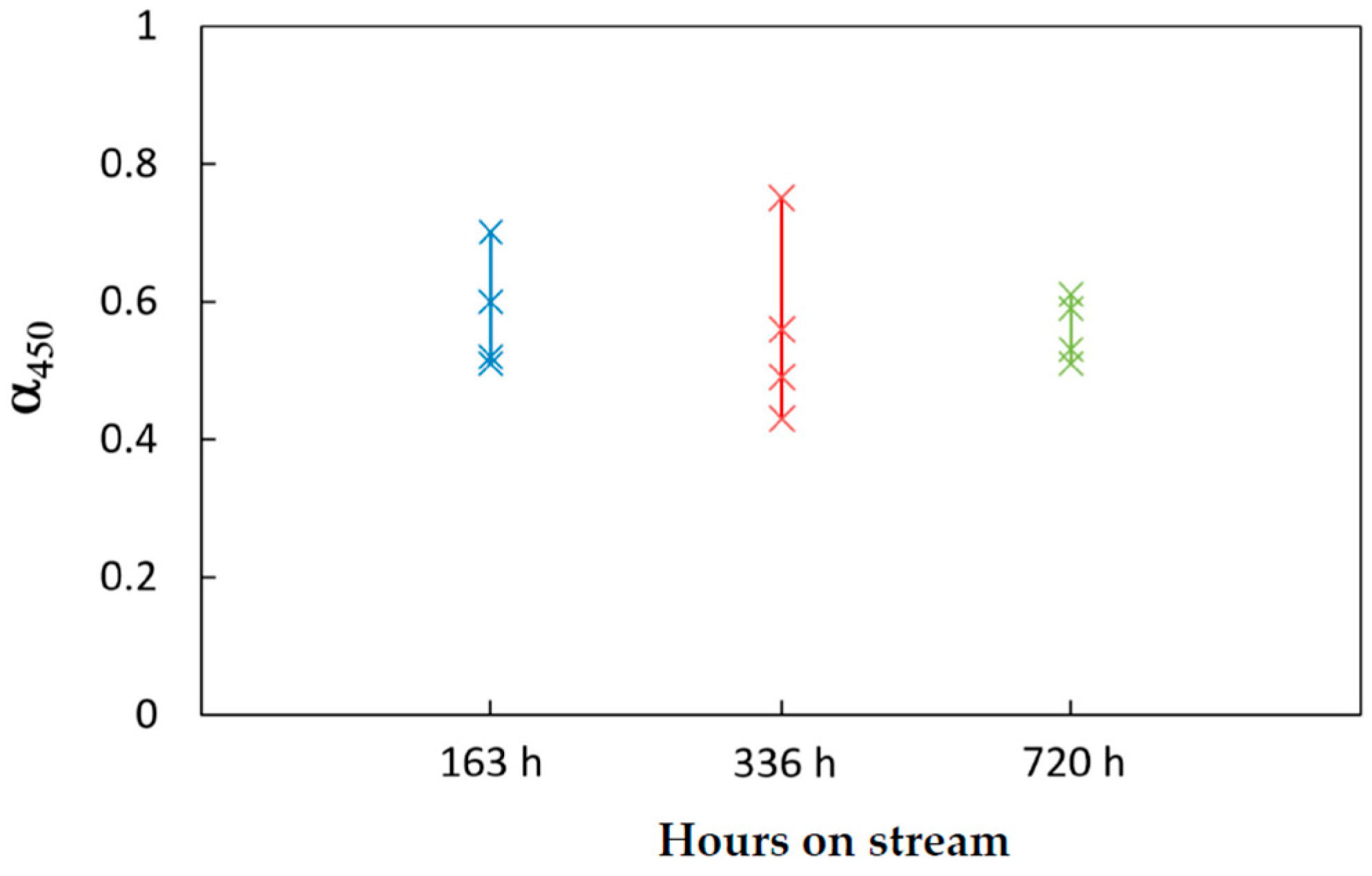
The same analyses were performed over the samples unloaded from the pilot scale reactor after 336 and 720 h on stream. The deactivation of the various layers was estimated accordingly, by the evaluation of the parameter α. An overall representation of the estimated values of the activity factor is reported in
Figure 5.
The largest variability was observed among the catalyst samples unloaded after 336 h, where a residual activity in between 43 and 75% was measured. However, the run had been characterized by several shut-downs and start-ups, which might make the long-term operation more “stressful” for the catalyst and the reactor. Instead, after 720 h on stream of a steady run, the residual activity of the catalyst varied in a narrow range, that is in between 50 and 62% throughout the bed.
An overall qualitative analysis of data suggests that while the deactivation was more pronounced at the reactor entrance, it was less pronounced across the bed. Remarkably, the deactivation of the top catalyst layer of the bed was kept at around 50% during time on stream; the activity profile of the rest of the bed narrowed above such a value. This spatial and temporal activity decay is coherent with deactivation kinetics due to sintering and coking [
34,
35].
TPO analyses confirmed that C-accumulation was more important at the reactor entrance and decreased progressively along the bed (examples of the adopted TPO procedure and evaluation of total evolved C are reported in
Figure S5 and
Table S1 in the
Supplementary Material). However, repetition of the kinetic test after TPO showed that the activity of the first layer remained almost unchanged after C-removal. This seems to suggest that stable changes of the catalyst surface, other than coking, had occurred.
Sintering, metal oxidation, volatilization or reactions with the support are some of the proposed deactivation mechanism for Ni-based or noble-metal-based steam reforming catalysts.
Ligthart et al. [
36] have studied the influence of particle size on the activity and stability of supported Rh catalysts and found that the initial intrinsic reaction rate has a linear correlation with the metal dispersion, independent of the nature of the support; these results, which confirmed previous results from Andersson et al. [
37] and Wei and Iglesia [
31], led the authors to conclude that the dissociative adsorption of CH
4 is the rate controlling step effecting dispersion related to the increasing density of defect (corner and edge) sites with decreasing particle size. The deactivation process would thus be related to a loss of such defect sites; this would occur via oxidation of very small particles under the steam reforming operating conditions and would be the cause of catalyst deactivation with metal nanoparticles below 2.5 nm. Sintering of metal particles was excluded.
These mechanistic results were later confirmed by Zhu et al. [
38] for Pt-based catalysts, in which case it was proposed that high temperature deactivation occurs due to poisoning by carbonaceous species such that the rate of surface OH/O species becomes too low compared to the rate of surface CH intermediate, thus hindering their gasification to CO and H
2. This mechanism of deactivation would occur at lower temperature for Pt than for Rh because of the lower Pt–O bond energy.
4.3. Full Reactor Modelling
The annular steam reforming reactor was modelled by assuming the following geometrical parameters: Rin = 0.11 m, Rout = 0.84 m, total length L = 0.75 m. A total volume of 6 l of catalyst, with an overall dilution ratio of SiC/catalyst = 4.2 by weight was considered. The reactor was modelled by assuming that the SiC particles were distributed unevenly, such that the dilution was increasing along the bed. Additionally, the input gas temperature of 600 °C, with a Steam/C ratio of 3.5 (which corresponds to an input molar concentration of CH4 of 22.2%) were assumed. The simulations explored the effect of load, catalyst activity and heat distribution.
In each simulation, the assigned total thermal load from the heating system (burner and flue gases) was derived from an independent thermodynamic calculation; in fact, the heat input necessary to obtain an outlet reformate at 650 °C, with a residual concentration of CH4 of 2% by volume and equilibrated WGS was calculated and assigned. Except for the cases where the effect of heat distribution was explored, q(z) was assumed constant along the axial coordinate.
The constraints on temperature and composition of the reformate were the results of an overall optimization of the thermal management of the fuel processor and of the stability of the carpentry. In fact, by partly limiting the NG conversion, and thus partly lowering the CO concentration in the reformate, a decrease of the heat release across the WGS reactor is expected. Besides, the values of 650 °C for the outlet reformate stream and 700 °C for the reactor skin have been identified as a maximum threshold to guarantee long term integrity of the fuel processor (e.g., materials, weldings) and best heat recovery in the heat exchanger was located in between the steam reformer and the WGS reactors.
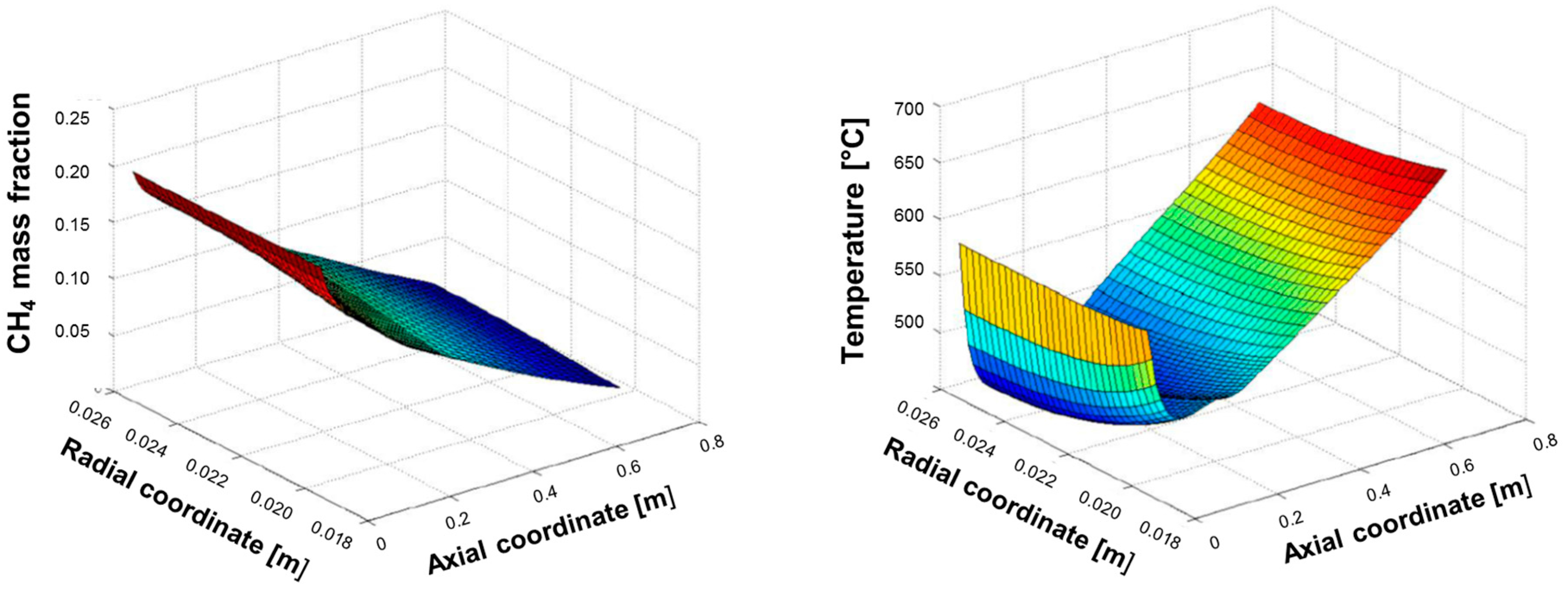
Figure 6 shows the spatial evolution of CH
4 concentration and temperature, calculated at the flow rate of CH
4 of 1.25 Nm
3/h corresponding to a total thermal load at the burner of 2.92 kW.
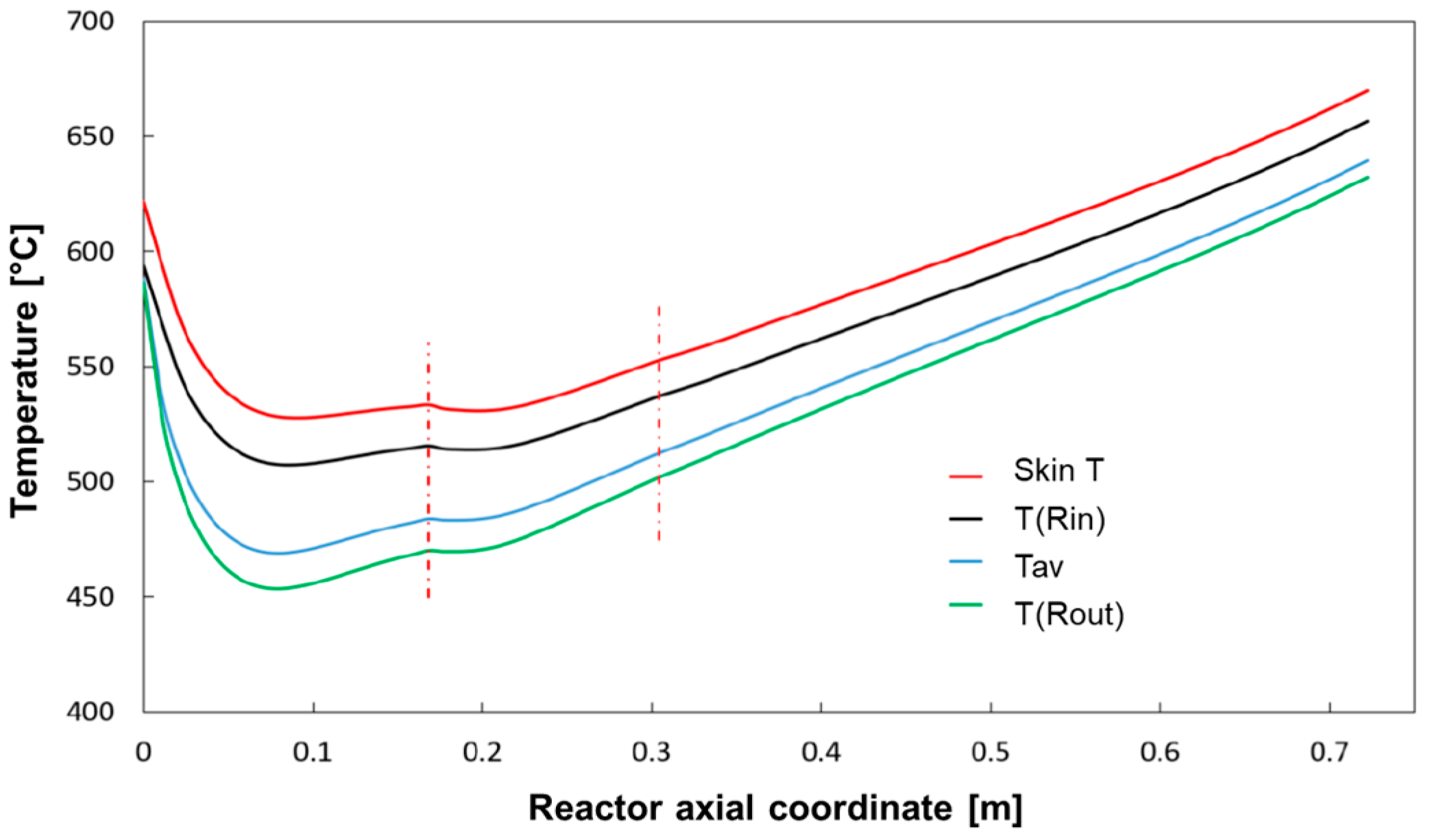
The simulation shows that methane consumption proceeded progressively across the catalyst bed length, and that the temperature of the reacting mixture passed through a minimum; for the sake of clarity, the same temperature distribution is represented in
Figure 7, where characteristic temperatures have been plotted:
Tw, that is the inner skin temperature,
T(
Rin) and
T(
Rout) that is the temperature at the radial boundaries of the catalytic bed, and
Tav, that is the average temperature of the bed across the section, was calculated as:
At the very entrance of the catalytic bed, the temperature of the reacting stream (entering the bed at 600 °C) is predicted to rapidly decrease and pass through a minimum at about 7 cm distance from the inlet; in this entry zone, the rate of steam reforming is so high that the heat consumed by the reaction prevails over the heat flux provided by the external source. Herein, important radial gradients are established; a gap of about 20 °C is predicted at the wall-bed interface at Rin and the bed average temperature is about 50 °C lower. Downstream from the entry zone, the temperature of the reactor rises progressively driven by the external heating and the importance of radial gradients becomes less important at increasing axial coordinate.
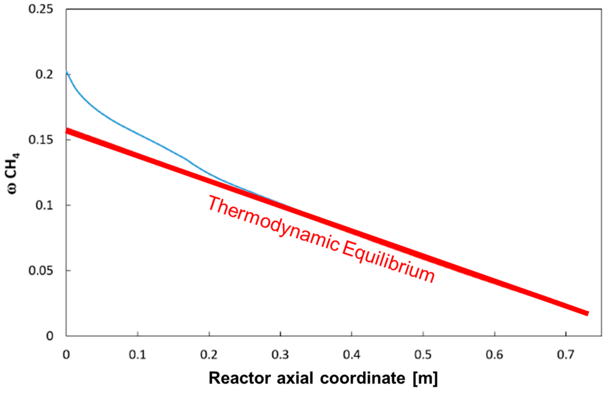
For the same case,
Figure 8 reports the calculated average methane concentration, evaluated according to the formula:
The Figure also plots the expected evolution of CH4 concentration when assuming thermodynamic equilibrium at the local value of the integral heat flux (the so-called Gibbs reactor). The comparison shows that the reactor operates under a kinetically controlled regime only in the inlet portion (which extends till the coordinate 20–25 cm), while it tends to become thermodynamically controlled along the rest of the bed.
In other words, under the operating conditions considered, the rate of the chemical process represents the controlling step of the reactor performance only in the first third of the bed, while the input heat flux becomes the limiting factor for the rising of temperature and the consumption of methane downstream.
4.4. Parametric Analysis of the Full Scale Reactor
A parametric analysis was then performed to evaluate the effects of load, catalyst deactivation and heat flow distribution.
4.4.1. Effect of the Input Load
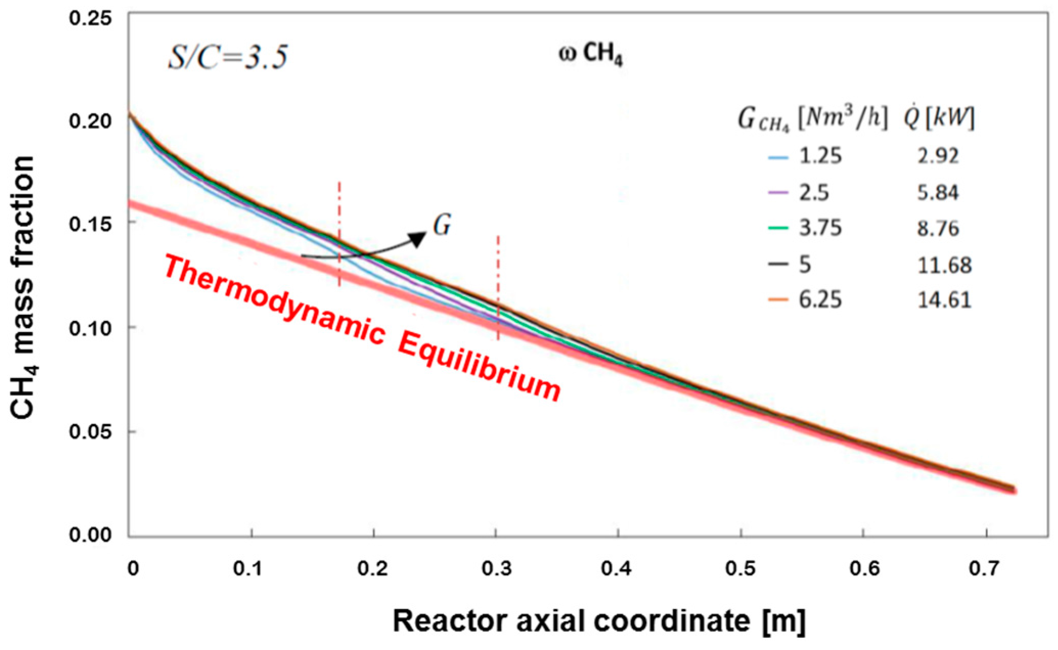
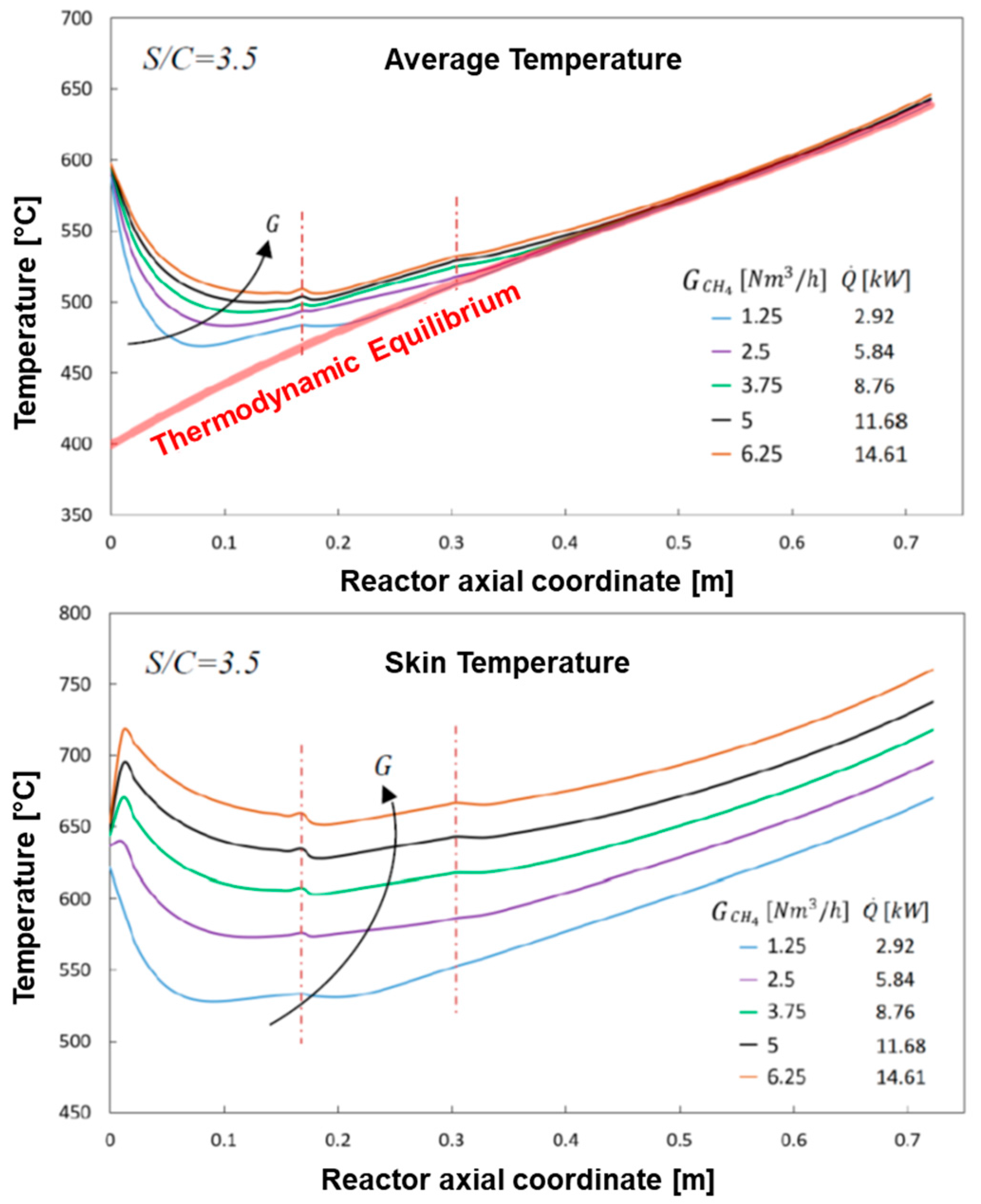
The cases of increase of the input flow up 6.25 Nm
3/h of CH
4, paired by the corresponding increase of the heat load up to 14.61 kW were simulated; the calculated profiles of methane concentration are reported in
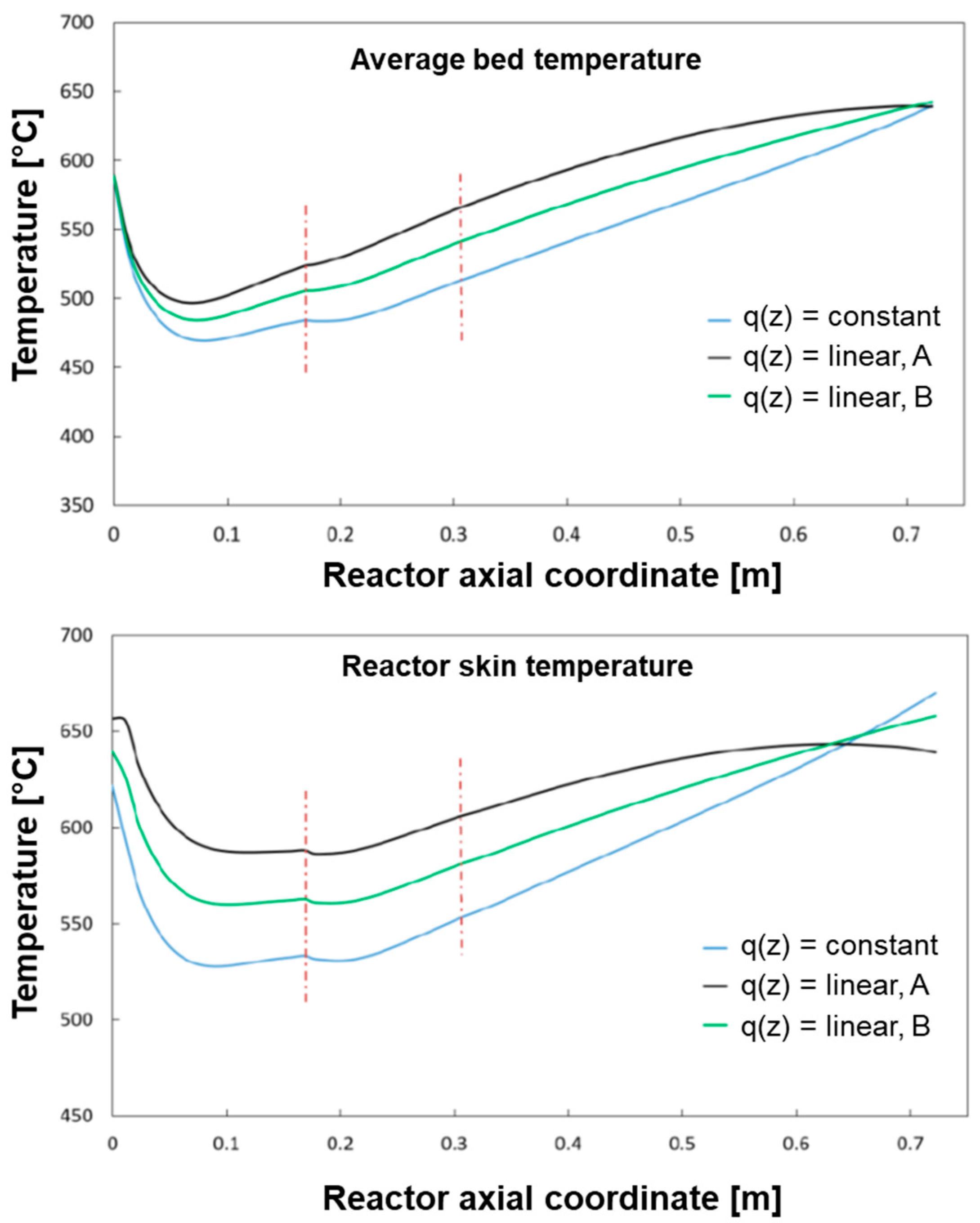
Figure 9, while the calculated temperature profiles of the gas stream (average) and of the reactor skin are reported in
Figure 10.
As expected, the progressive increase of space velocity reduces the consumption rate of CH4 such that the axial coordinate of the bed where the reactor enters in a thermodynamically controlled regime shifts progressively downward; still, the assumed sizing of the reactor is sufficient to guarantee the target of conversion. This is accompanied by a progressive change of the axial temperature profile of the bulk stream, where a smoothening of the minimum is observed; besides, the target of 650 °C outlet temperature for the reformate is guaranteed even at highest investigated load.
Remarkably, the skin temperature profile of the reactor changes in such a way that an initial temperature peak appears and becomes more and more pronounced at increasing load. At the CH4 flow rate of 5 Nm3/h and total heat load of 11.68 kW, the wall temperature approaches 700 °C at the reactor inlet and exceeds 700 °C in the ending portion, thus entering in an unsafe condition for the mechanical stability of the fuel processor.
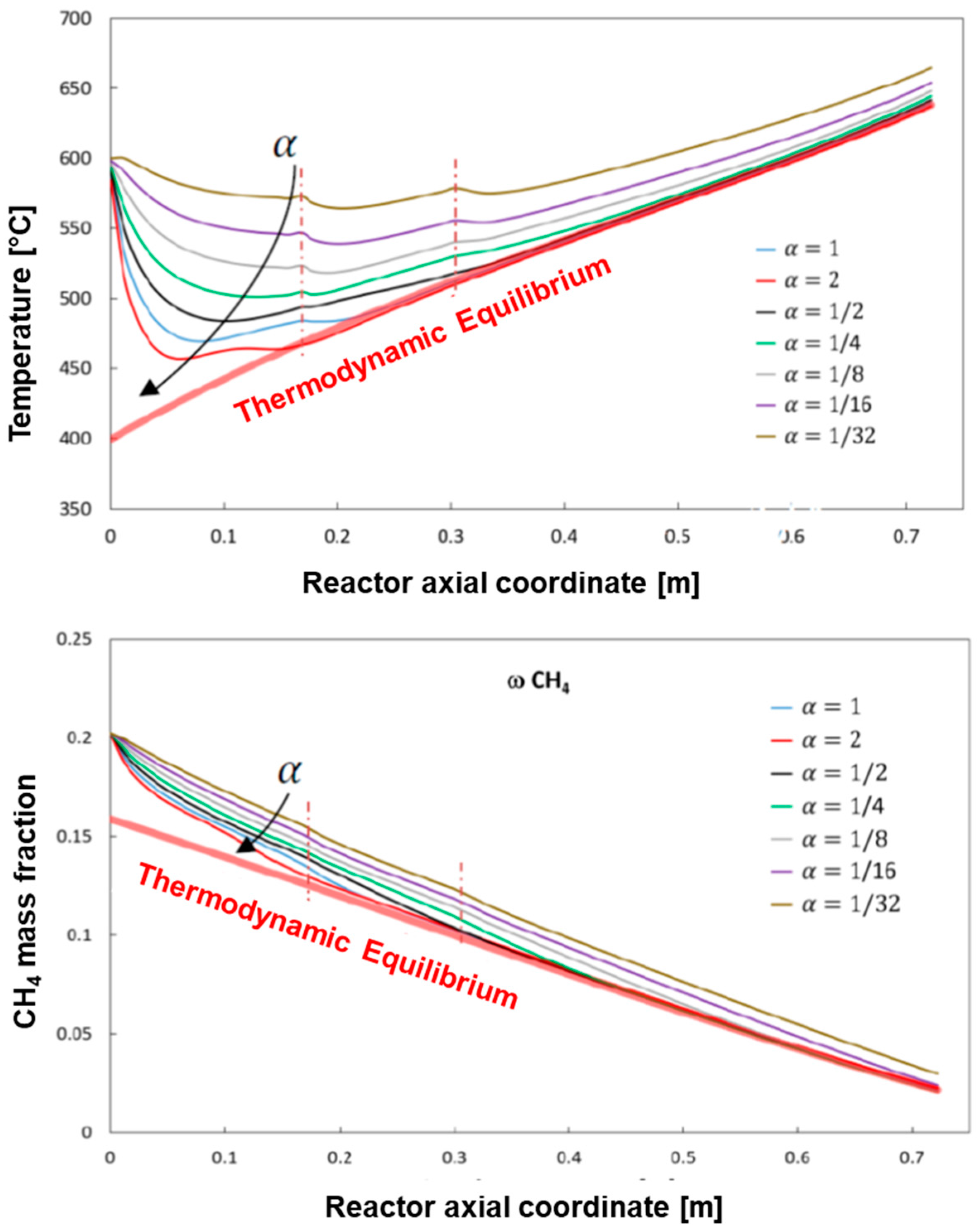
4.4.2. Effect of Deactivation
Figure 11 reports the results of simulations where, while keeping constant the input conditions of the reference case at low flow and heat load, the activity of the catalyst was varied by changing the value of α from 1 (fresh catalyst, reference case) down to 1/32. The case of α = 2 (catalyst with twice the reference intrinsic activity) is also represented for comparison.
At progressively decreasing activity, the reactor performance changes significantly, since less and less heat is consumed by the reaction process with consequent progressive increase of both the average gas temperature, and the reactor skin temperature (not reported). Besides, at decreasing catalyst activity the conversion of methane slows down along the reactor and longer bed lengths are needed to reach the thermodynamic control.
Considering the measured extent of deactivation during long term tests, the most interesting and representative cases are those where the residual activity (α) is in between ¼ and ½ of the fresh catalyst. The simulations show that the reactor is sufficiently oversized to face such a level of deactivation, still guaranteeing the target performance in terms of CH4 conversion and outlet gas and wall temperature.
Instead, the assumed sizing becomes insufficient to meet the specifications if a more severe deactivation occurs; if the residual activity approaches one order of magnitude reduction from the fresh catalyst, then the reference sizing becomes critically sufficient to guarantee the required conversion of CH4, but the calculated outlet temperature rises by 20–30 °C from the case of fully active catalyst.
A more demanding condition was simulated by assuming a CH4 flow of 3.75 Nm3/h and heat load of 8.76 kW. A reduction of the catalyst activity down to one fourth of the initial activity still meets the design specifications in terms of composition and temperature of the reformate as well as maximum temperature of the reactor skin. A further decrease of the catalyst activity brings the skin temperature above 700 °C. This constraint is then largely exceeded (about 30 °C) if a loss of activity down to 1/16 of the fresh catalyst is simulated; the loss of conversion and the increase of outlet temperature is less severe.
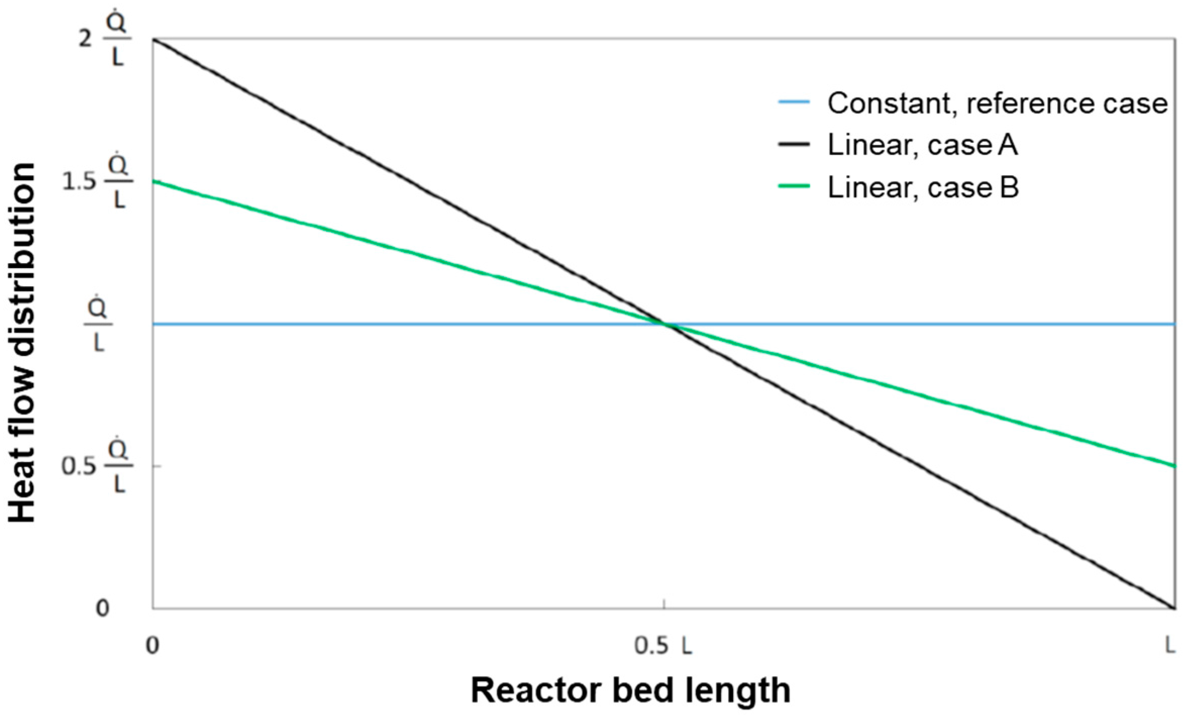
4.4.3. Effect of the Heat Flux Distribution
The base case of constant heat flux distribution was compared with the following two cases of linear heat distributions as represented in
Figure 12:
Case B is characterized by having twice the heat flux of the base case at z = 0 cm and zero heat flux at z = L. Case A represents an intermediate distribution in between the reference case of constant flux and case B.
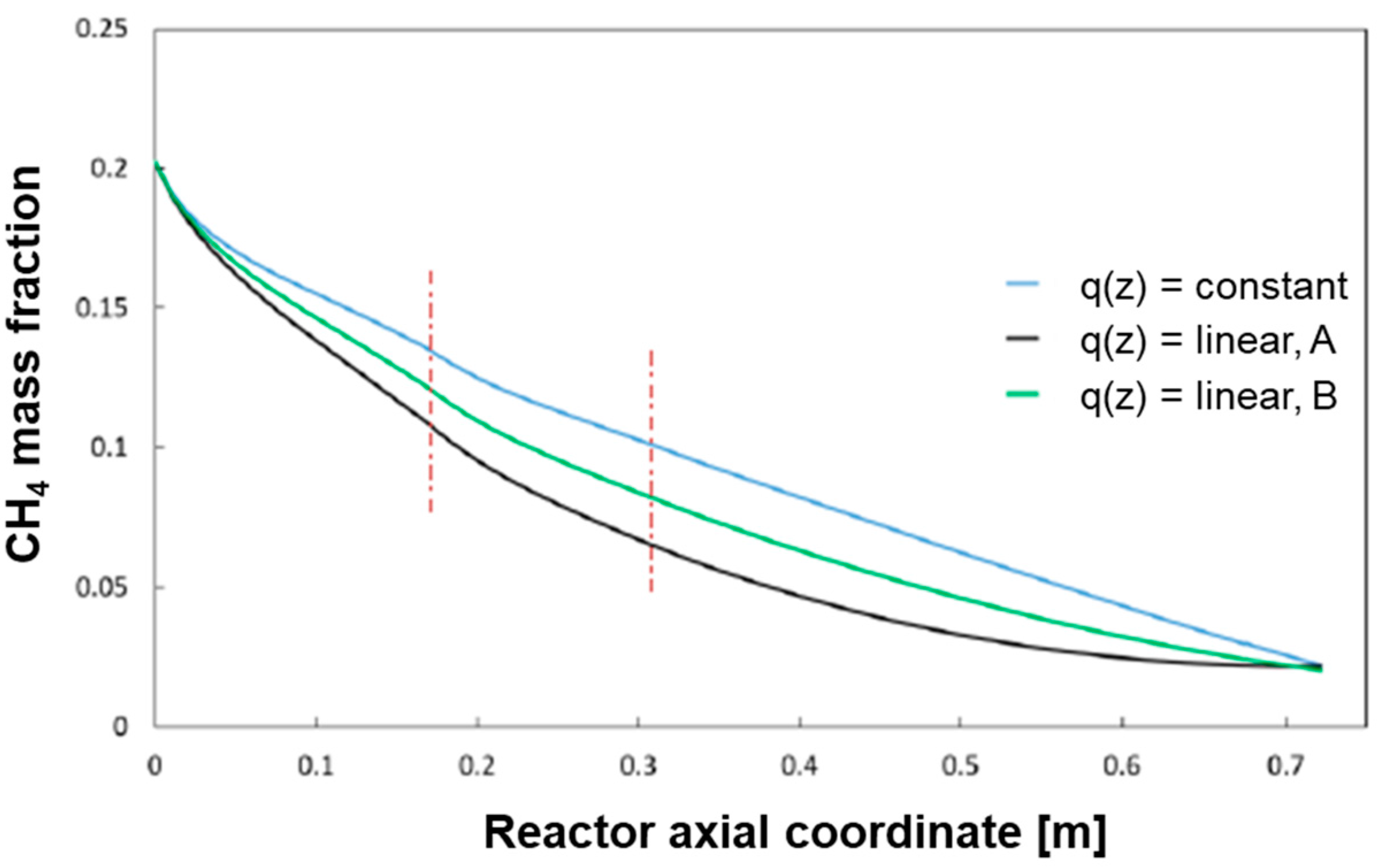
The results of the simulations (which refer to the case of CH
4 flow of 1.25 Nm
3/h and Steam/C = 3.5) are reported in
Figure 13 and
Figure 14.
The progressive “concentration” of the heat flux at the reactor entrance produces an increase of the temperature in the gas phase and, thus a more pronounced conversion of CH4 in the entrance zone of the reactor with respect to the reference case. The average temperature profile of the bed becomes more and more uniform.
Also, the wall temperature profile tends towards a condition of more even distribution; however, higher inlet temperatures are experienced by the reactor skin; although under the conditions herein simulated, this maintains below the threshold limit of 700 °C, it is recognized that, at increasing load, the respect of such a constraint could become critical.
5. Discussion
The study covers several aspects related to the development of a CHP prototype.
Long-term steam reforming tests were performed using an experimental set-up that mimics the operation of the full-scale unit; it consists of an externally heated tubular reactor that, with exclusion of the different nature of the heat source (an oven), operates under conditions (flow rate/catalyst volume, feed composition, 650° average heating temperature) representative of the operation of a real fuel processor reactor. However, this unit cannot be treated as a screening unit. The integral data obtained by analysis of the product mixtures did not provide any appreciable evidence of catalyst deactivation. This is due to the fact that the reactor was oversized, and, similarly to the full scale reactor, the outlet conversions and syngas composition were largely controlled by thermodynamics and not as sensitive to changes of the catalyst surface.
This is the reason why a lab-scale equipment and methodology for kinetic investigation were developed and applied to compare the activity of fresh (unused) and aged catalysts. Only by testing the steam reforming process at very high space velocity in order to contrast the effect of the reaction reversibility and at sufficiently high reactant dilution, in order to minimize any temperature gradient across the catalyst bed, reliable and informative data were obtained on the effective rate of the forward chemical process. Thus, only by performing experiments under operating conditions very distant from the real operation of the fuel processor, meaningful information on the extent of deactivation was obtained which were useful for the design of the full scale reactor.
Within the hours-on-stream intervals investigated, a decline of the catalyst activity was measured; this asymptotically tended towards a condition were the activity was about half the initial value. The commercial catalyst showed a satisfactory stability.
Although a detailed kinetic investigation was beyond the scope of the present work, few explorative experiments confirmed that steam reforming over the commercial catalyst is kinetically limited by CH
4 activation, but not limited by H
2O activation and was partly hindered by the formation of the products; this confirmed that a rate expression of the form of Equation (4) could be used for the reactor modelling. Notably, Equation (4) was developed in previous studies from our laboratory from a detailed kinetic investigation of the partial oxidation and steam reforming of CH
4 over a Rh/Al
2O
3 catalyst and analogous expressions were developed for several hydrocarbon fuels, suggesting that the activation of all the fuels have a common step of activation of the first C–H bond [
39,
40]. In view of design applications, it is important to observe that such rate expressions were successfully applied to the simulation of pilot scale autothermal reformers operating with undiluted hydrocarbon/air mixtures [
41,
42], proving also their numerical stability when used in the solution of differential and algebraic equations of mass and heat balances.
The model of the full-scale reactor was developed by imposing the external heat load necessary to satisfy the specifications of a residual concentration of CH4 in the reformate of 2% and output temperature of 650 °C. The additional constraint of maximum 700 °C for the reactor skin temperature was considered.
A reference case with low flow rate, where the space velocity (referred to as the catalyst volume) is about 1300 h−1, fully satisfies the specifications; indeed, the prototype layout is such that the volume occupied by the burner (steam reforming system) allows for an oversizing of the catalyst bed. The analysis of the calculated temperature and composition profiles of the reference case showed that only in the first third of the reactor the steam reforming process is kinetically controlled; in this zone, in fact, the temperature passes through a minimum, decreasing at the very inlet from the input pre-heat temperature due to the local unbalance between external heat flux and inner heat consumption due to the reaction. Further downstream, the evolution of temperature and conversion are instead limited by the external heat flux, such that the local value of conversion corresponds to the expected conversion in a Gibbs-reactor, where thermodynamic equilibrium is locally achieved and the reactor temperature gradually increases in response to the heat input.
A parametric analysis showed that the sizing of the reference case is robust and conservative since the reactor specifications are satisfied after the increase of the reactor load up to several times the reference flow and heat load, and even after an activity loss down to ¼ of the initial activity.
Eventually, though, the increase of the input loads and of the deactivation lead to an increase of the wall temperatures and an inefficient conversion of CH4.
It was then verified that, similar to the case of industrial steam reformers where the input heat load is maximum at the very entrance of the catalyst tubes where the reaction rate is maximum, also in the present small scale reformer the performance may be improved by increasing the heat load at the reactor entrance. This may be relevant for the operation and design of the burner.

 ,
, 