Effect of Concentration on Amine-Modified Kenaf as a Sorbent for Carbon Dioxide Adsorption in a Pressure Swing Adsorption System

1
Shizen Conversion and Separation Technology ikohza (SHIZEN), Department of Chemical Process Engineering, Malaysia-Japan International Institute of Technology (MJIIT), Universiti Teknologi Malaysia (UTM), Kuala Lumpur 54100, Malaysia
2
Department of Energy Engineering, Faculty of Chemical and Energy Engineering (FCEE), Universiti Teknologi Malaysia (UTM), Johor Bahru 81310, Malaysia
*
Author to whom correspondence should be addressed.
ChemEngineering 2018, 2(2), 23; https://doi.org/10.3390/chemengineering2020023
Submission received: 12 March 2018
/
Revised: 13 April 2018
/
Accepted: 10 May 2018
/
Published: 21 May 2018
Abstract
:Amongst the strategies applicable for CO2 capture and sequestration, the adsorption process has a high potential to be applied as an alternative CO2 separation strategy as it offers large adsorption capacity, requires low energy for regeneration with economical equipment cost, prevents corrosion problems, and provides ease of applicability. Inspired by the most applicable amine-based chemical absorption for CO2 capture, the modification of adsorbent by amine was first considered and then investigated. This study introduces kenaf (Hibiscus Cannabinus L.) as a potential low-cost material in evaluating the effect of amine functional group concentrations on CO2 adsorption capacity. Monoethanolamine (MEA) and tetraethylenepentamine (TEPA) were impregnated on kenaf via a wetness impregnation method to achieve the aim. The ratios of amine to kenaf were varied at 1:2, 7:10, 1:1, 2:1, 5:1, 7:1, and 10:1. Then, the prepared amine-modified kenaf core sorbent was characterized using different morphology and structural characterization techniques such as a field emission scanning electron microscope (FESEM) analyzer and Fourier transform infrared (FTIR) spectroscopy. Results obtained through the analyses showed that amine (MEA and TEPA) were successfully impregnated on the kenaf core surfaces, and that amine concentrations have a significant effect on the morphological structures of the kenaf core support. The study on CO2 adsorption capacity was conducted in a pressure swing adsorption system (PSA). Results revealed that the highest CO2 adsorption capacity for MEA-modified kenaf adsorbent was achieved at an amine to kenaf ratio of 1:1 (2.070 mmol/g), while for TEPA-modified kenaf adsorbent at a ratio of 2:1 (2.086 mmol/g). The study on the effect of amine concentration on kenaf adsorbent is beneficial in introducing kenaf as a sorbent in capturing CO2.
1. Introduction
Recently, the rising concentration of carbon dioxide (CO2) in the atmosphere has been linked with global climate changes [1]. It is widely alleged that CO2 is the main cause of the greenhouse effect, and a large portion of the CO2 in the atmosphere is from the process of burning of fossil fuels [2]. Additionally, extensive studies on global climate change have predicted that the average global surface temperature will rise by 2 °C between 1990 and 2100 [3]. Based on the prediction, efforts to mitigate the continuous emissions of CO2 into the atmosphere have been considered a key measure to reduce greenhouse gases emissions in the short-term [4]. The efforts have been deliberated and actively implemented and have become a global issue including in Malaysia. In line with this, carbon capture and storage (CCS) has been introduced as a key tool in the global commitment to mitigate climate change [5]. The mitigation of CO2 concentration using the CCS technology is a prominent option and was established in Malaysia under the Intergovernmental Panel on Climate Change (IPCC) in 2007 with attention directed on the integration of climate change into sustainable development policies and relationships between mitigation and adaptation. Indeed, the CCS project is a key technology that should assist Malaysia in achieving the goal to combat this global issue by reducing the percentage of CO2 emissions by 40% in 2020 based on its level in 2005 [3].
CCS can be successfully achieved using several techniques such as amine-based liquid absorption, solid adsorption by adsorbents, cryogenic distillation, and membrane technologies [6,7,8]. Among the highlighted techniques, amine-based liquid absorption is the most favored method and has been industrially practiced. Liquid absorption whether by chemical or physical methods is commonly regarded as the most mature technology that has been used for CO2 capture [5]. Nevertheless, amine-based liquid absorption for CO2 capture was revealed to suffer from some drawbacks such as requiring energy-intensive regeneration aside from needing a large absorber volume. It requires a low gas-liquid contact surface that leads to low CO2 loading, and among other problems, results in occurrences of solvent degradation, and production of corrosive products [9,10,11]. Thus, the adsorption process has been addressed as a promising alternative to tackle these drawbacks. Inspired by the most applicable amine-based liquid absorption method, adsorption by amine-impregnated adsorbent is presented in this paper. The adsorption process requires little energy for regeneration especially when the regeneration process is carried out through pressure reduction; other advantages include, low equipment cost, high CO2 adsorption capacity, corrosion prevention, and ease of applicability [12,13,14,15,16].
The success of this technique relies on the development of adsorbent. There are several materials that have been reported to show high affinity towards CO2 including porous carbonaceous materials, activated carbon (AC), zeolites, alumina silica, metal-organic frameworks (MOFs), carbon nanotubes (CNT), carbon molecular sieves (CMS), lithium zirconate, hydrotalcite, calcium oxide (CaO), and organic–inorganic hybrids [16,17]. In the pursuit of attaining low-cost adsorbent for capturing CO2, many researchers have investigated several agricultural materials such as ground coffee [18], almond shell [19], palm kernel [20], palm shell [21,22], coconut shell [22,23], olive stone [19], yeast [24], bean dreg [25], poplar anthers [26], bagasse [27], and chitosan [28,29]. A study found by Othman and Akil [30] revealed that the natural materials were potentially less harmful to the environment; have high affinity towards organic molecules mainly solvents and chemicals; operated well under a wide range of pressure, temperature, and humidity levels as well as being inert, safe to use, highly available, and cost-effective [30]. However, the utilization of these agricultural materials was restricted to the production of highly porous bio-carbon and activated carbon that involve energy and intensive time to be converted. In spite of this, a review conducted by Yu et al. [3] revealed that the CO2 adsorption and selectivity was improved by increasing the alkalinity of the sorbent surfaces via chemical modification.
In this study, kenaf (Hibiscus Cannabinus L.) was introduced as a potential green-based material for the production of low-cost adsorbent. Kenaf is a warm-season, short-day, and herbaceous annual plant that is related to cotton, okra, and hibiscus [31]. Kenaf belongs to the Malvaceae family that has a single, straight, and branchless stem that consists of soft and short fibers called the core, and outer fibrous bark comprising long fibers known as bast [31,32,33]. This study was conducted with the aims of preparing amine-based adsorbents derived from kenaf core and to determine the CO2 adsorption capacity. Thus, the production of a low-cost sorbent via chemical modification was one way forward. With regards to adsorption and desorption principles, a pressure swing adsorption (PSA) system was practiced. PSA is a cyclic adsorption process performed by periodical changes of pressure for continuous separation involving the gas stream [34]. This study concerns the preparation of amine-modified kenaf sorbent at different amine concentrations for the CO2 adsorption process. The CO2 adsorption capacity of the prepared samples was compared to the unmodified kenaf core (precursor) to determine the effect of amine modification on the CO2 adsorption capacities. The key criterion to define an efficient way to improve the CO2 adsorption capacity of a low-cost adsorbent was also pinpointed throughout this study.
2. Materials and Methods
2.1. Preparation of Materials
In this study, kenaf core without outer periphery bark (outer layer) was procured from the National Kenaf and Tobacco Board (NKTB), Kelantan, Malaysia. The kenaf core was presented in chip form in the sizes of 5 to 10 cm. The kenaf core in chip form was prepared to be used as a precursor by grinding and sieving into smaller particle sizes with a series of sequences, 125–249 µm, 250–299 µm, 300–499 µm, 500–999 µm, and ≥1000 µm, respectively. A study done by Zaini [35] revealed that kenaf core in the size range of 300–499 µm indicated the highest CO2 adsorption capacity rather than other compared sizes. The types of chemicals that were used are monoethanolamine (MEA) and tetraethylenepentamine (TEPA) which were procured from the QRec and Merck Companies, respectively. Both of these amine type chemicals are highly concentrated reagent grades with purity of more than 98%. Methanol solvent was also purchased from Merck Company to facilitate the preparation of the amine-modified samples. For the gas adsorption and desorption studies, a high concentration sources of carbon dioxide (CO2) and nitrogen (N2) were procured from Mega Mount Industrial Gases Sdn. Bhd. Besides, a high purity grade of helium gas (He) and air were also utilized in this study to act as a carrier gas and an injector gas for Gas Chromatography 7820A (GC, Agilent Technologies, Santa Clara, CA, USA).
2.2. Preparation of the Amine-Modified Kenaf Sample
In this study, kenaf core without outer periphery bark (bast) was selected as a precursor for the preparation of the amine-modified sample. The amine-modified kenaf sample was prepared via the conventional method known as the wet impregnation method. The types of amines chosen were monoethanolamine (MEA) and tetraethylenepentamine (TEPA). The ratios of amine to kenaf were varied at 1:2, 7:10, 1:1, 2:1, 5:1, 7:1, and 10:1. Methanol was selected as a solvent for the impregnation procedure. Firstly, kenaf core was ground and sieved to a particle range of 300–500 µm prior to being wetted out in methanol solvent with the ratio of solid to liquid of 1:20. The kenaf and methanol solvent were maintained in contact for 20 min in two stages before drying overnight. For the other part, the alcoholic amine solution was prepared by mixing amine with different concentrations of methanol solvent for 20 min. Then, the air-dried kenaf was added to the prepared alcoholic amine solution and kept for 15 min prior to being magnetically stirred for 5 h. Finally, the resulting amine-impregnated kenaf sample was filtered and air-dried, while the alcoholic amine-solution was decanted for further analysis. The dried kenaf modified with amine (MEA and TEPA) was kept in an air-tight container for further use.
2.3. Structural Characterization Analysis
The MEA-modified kenaf and TEPA-modified kenaf samples were subjected to structural characterization analysis by using Fourier transform infrared (FTIR) spectroscopy and a field emission scanning electron microscope (FESEM) analyzer. For the FTIR analysis, the sample underwent testing in the mid-infrared region positioned in the range of 4000–370 cm−1 (wavenumber in x-axis). FTIR analysis using standard IR spectra provides a quick and simple qualitative technique to detect the presence, absence, and/or shrinkage of the functional group existing in the amine-modified kenaf samples. The presence of N–H bonds is a major consideration to confirm the impregnation of the amine functional group on the kenaf surface support. The FESEM analysis conducted provided a view of the surface textures of the sample before and after the amine-impregnation procedure. The sample was coated with a thin layer of gold in order to prepare a suitable and necessary surface condition and prevent electrostatic charging during the scanning phase.
2.4. Elemental Characterization Analysis
The elemental compositions existing in the samples were determined using energy dispersive X-ray spectroscopy (EDX). The EDX quantification analysis was conducted using the MEA and TEPA modified kenaf core samples. The EDX analysis was initiated by coating the sample with a thin layer of gold film in order to prepare a conductive surface condition and to prevent electrostatic charging with the help of vacuum gold sputter coater (Model: Bio-Rad, Hercules, CA, USA) that operated at a pumping pressure of 0.8 mbar with current coating of 20 mA for 90 s. Then, the prepared sample was placed on the plate and the image was focused at the specified magnification. The elemental composition data was collected at three different locations to obtain the average value of the elemental data.
2.5. CO2 Adsorption and Regeneration Studies
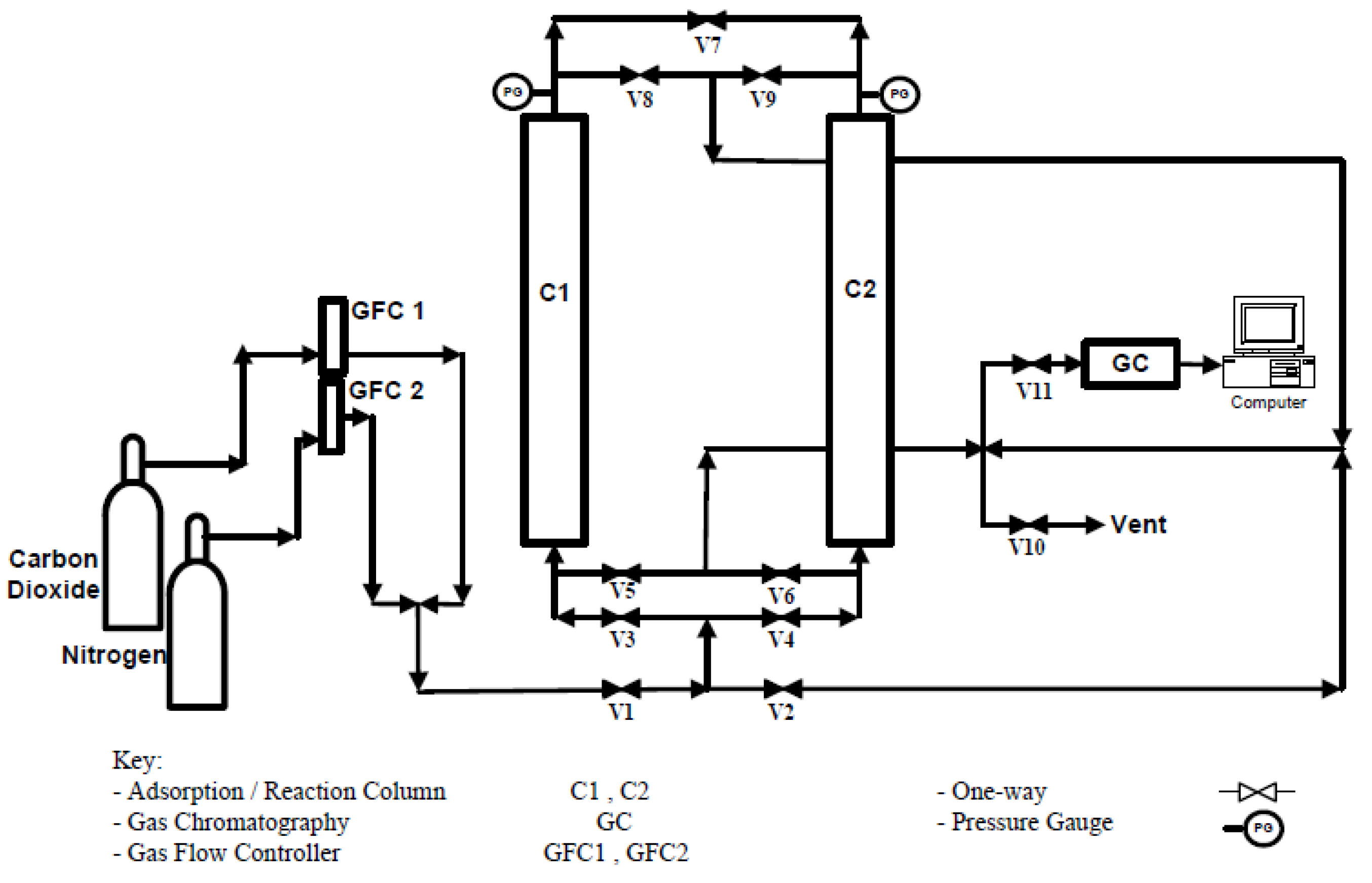
The CO2 adsorption and regeneration studies were conducted with the aid of a double-column pressure swing adsorption system (PSA). Each of the columns had specific dimensions as follows: internal diameter of 3.5 cm (1.378 inches), height of 15 cm (5.906 inches), and made of 3 mm (1/8 inch) stainless steel tube. The PSA system was connected to Gas Chromatography (Agilent 7820A GC system) to determine the peaks of the raffinate gases that left the adsorption system. The GC system was operated with the aid of carrier and injector gases. For this study, helium (He) and air functioned as a carrier and injector gas, respectively. Carbon dioxide (purity of 99.999%) and nitrogen (purity of 99.999%) gases were purchased from MegaMount Industrial Gases Sdn. Bhd. (Senai, Malaysia) and used for the adsorption and regeneration processes, respectively. The PSA operation system was operated in four steps, which were pressurization, adsorption, desorption, and purging. The adsorption process was fixed at 1.5 bars with a flowing rate of 300 cm3/min and retention time of 5 min. The regeneration process took over after the adsorption step by reducing the pressure to 1 bar. The schematic diagram of the double-column PSA system is represented in Figure 1.
3. Results and Discussion
3.1. Structural Characterization Analysis
3.1.1. FTIR Characterization Study
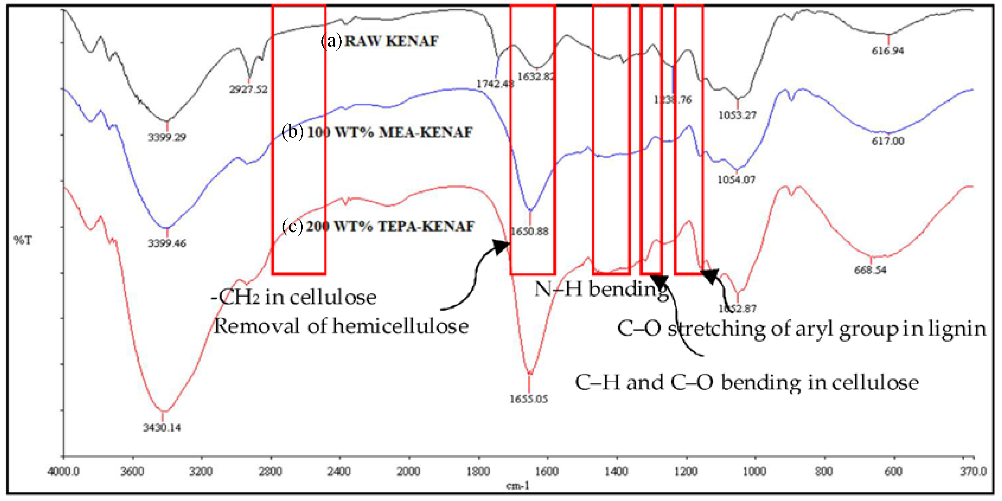
An FTIR characterization study was achieved to determine the presence of amine functional groups and the shrinkage of peaks after undergoing the amine wetting impregnation procedure. Figure 2 shows the IR spectra of the amine-modified kenaf sample. The IR spectra of amine-modified kenaf samples were compared to the IR spectra of raw kenaf core (precursor).
Referring to the presented IR spectra in Figure 2, the raw kenaf core and amine-modified kenaf samples had broad bands in the range of 3300–3400 cm−1 that represented the stretching of intra- and inter-hydroxyl groups (O–H) in the cellulose compound. The peak in the range of 2800–3000 cm−1 indicated the aliphatic alkyl group (C–H) stretching of –CH2 [36]. However, the disappearance of the sharp peak at 2861 cm−1 in the amine-modified kenaf samples was due to the shift of stretching –CH2 in cellulose. Moreover, the IR spectra at 1742 cm−1 in the raw kenaf core was associated with the C=O stretching of the acetyl and ester group of hemicellulose [37,38]. The absence of this peak in both amine-modified kenaf samples explains the elimination of hemicellulose after impregnation of the amine on the kenaf surface. In addition, the presence of a sharp peak at band position of 1500 cm−1 in both amine-modified kenaf samples was ascribed to the stretching vibration of N–H bending. The determination of N–H vibration proved impregnation of the amine functional groups on the kenaf surface. Moreover, the absorbance peak at 1377 cm−1 referred to the bending vibrations of C–H and C–O bonding of the aromatic ring in the polysaccharide [39,40]. The disappearance of this peak in amine-modified kenaf samples defined the shift of C–H and C–O bonds in the kenaf cellulose. The sharp peak at 1238 cm−1 in the raw kenaf sample represented the C–O stretching of the aryl group in the lignin [40]. The shrinkage of this peak after the impregnation of MEA and TEPA elucidated the shifted C–O stretching bond of lignin. Based on the FTIR analysis, there were several functional groups either shifting, appearing, or disappearing after the impregnation of MEA and TEPA that confirmed the presence of functional amine group on the kenaf structure surface.
3.1.2. FESEM Characterization Study
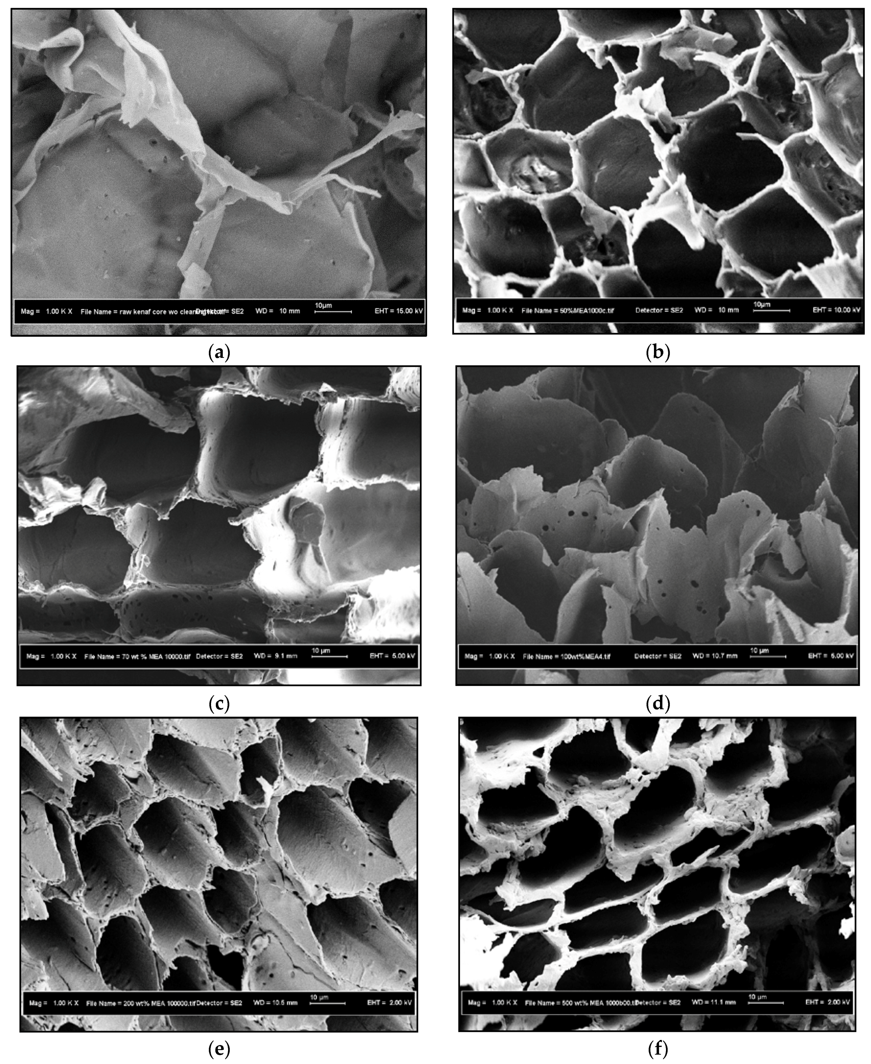
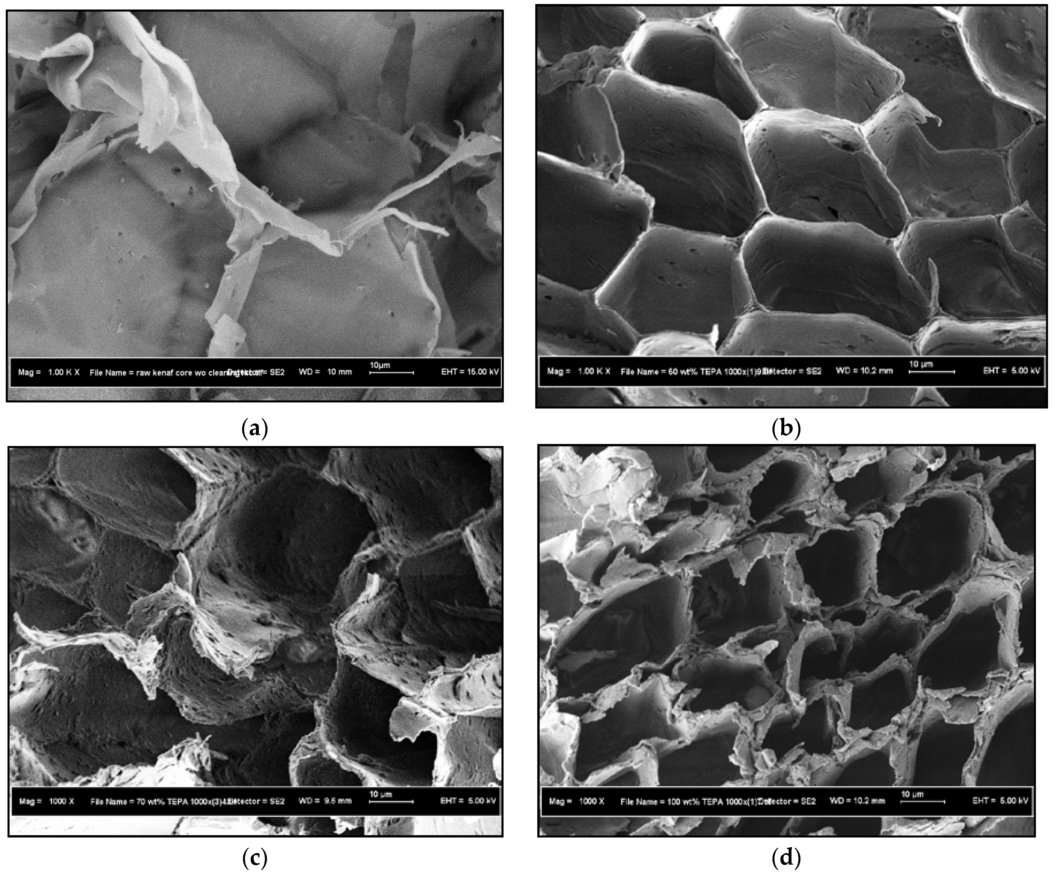
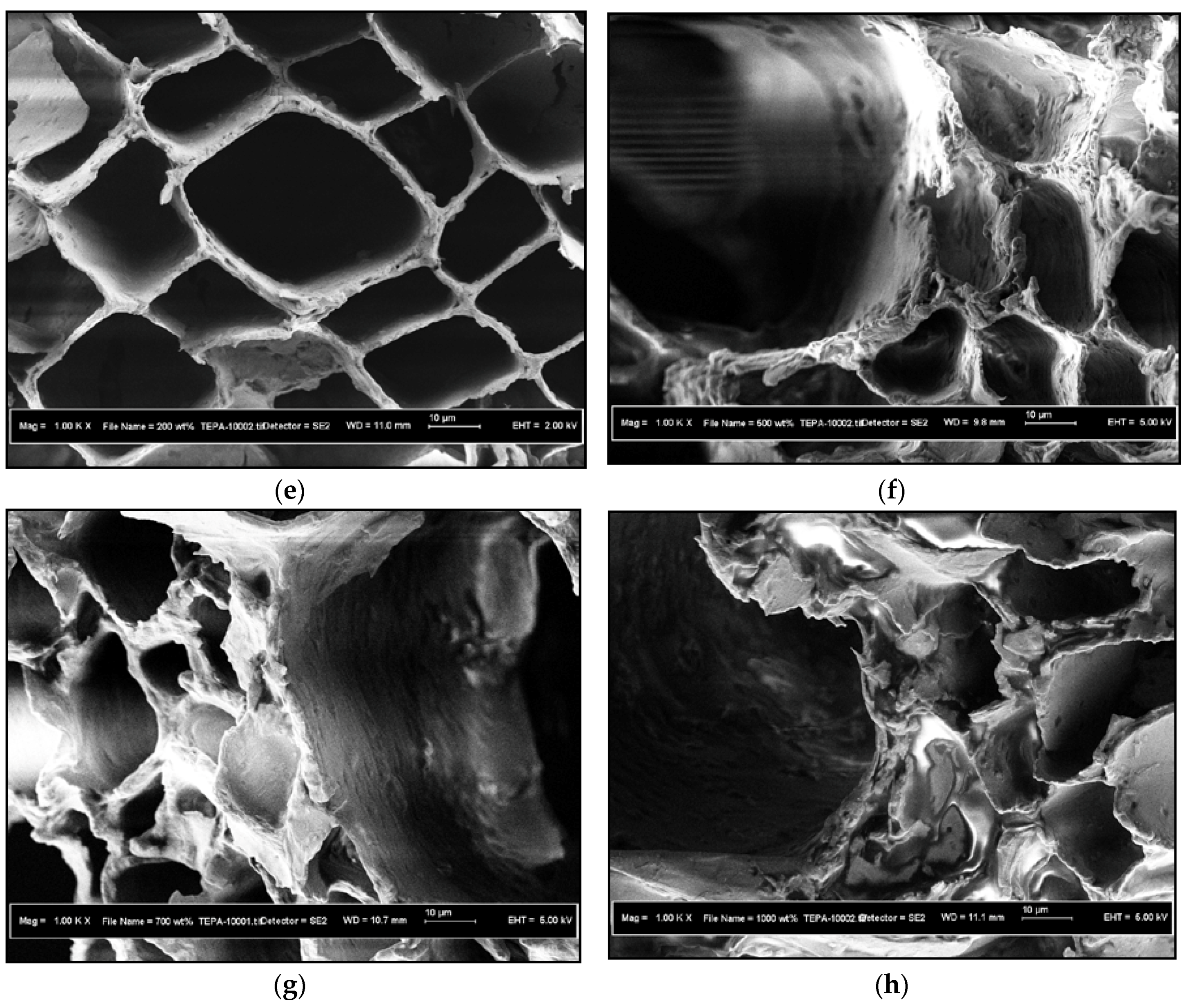
In this study, the effect of amine concentrations on kenaf material was evaluated by varying the ratio of amine to kenaf at 1:2, 7:10, 1:1, 2:1, 5:1, 7:1, and 10:1. The cross-sectional morphologies of MEA and TEPA-modified kenaf at different concentrations are presented in Figure 3 and Figure 4, respectively.
Based on the presented surface morphology in Figure 3, the impregnation of MEA with different concentrations affected the pore structure of the kenaf support. Different MEA concentrations would be expected to form different enlargements and pore structures of kenaf. As shown in Figure 3b, the MEA to kenaf ratio of 1:2 exhibited a clear and apparent pore structure. The addition of MEA in the ratio of 7:10 as shown in Figure 3c created a rough and jagged pore structure and became partially broken when the MEA concentration was increased to 1:1 ratio (Figure 3d). Then, further increase in the MEA concentration to kenaf of ratio 2:1 caused a clear and larger pore opening structure as presented in Figure 3e. The kenaf structure developed a thicker and large uneven pore opening after impregnation of MEA to kenaf with a ratio of 5:1 as shown in Figure 3f. The additional MEA concentration to kenaf with the ratio of 7:1 formed larger pore opening sizes as compared to 2:1 and 5:1. However, the smaller heterogeneous pore openings seemed to be broken and cracked. Finally, by increasing the MEA concentration to kenaf up to a ratio of 10:1 caused imminent destruction of some of the wall structures and formed a large pore size as indicated in Figure 3h. This result was in line with the study carried out by Anita et al. [41] who also revealed that higher MEA concentration induced agglomeration of a MEA-Si-MCM-41 support and blocked the sites for the adsorption process.
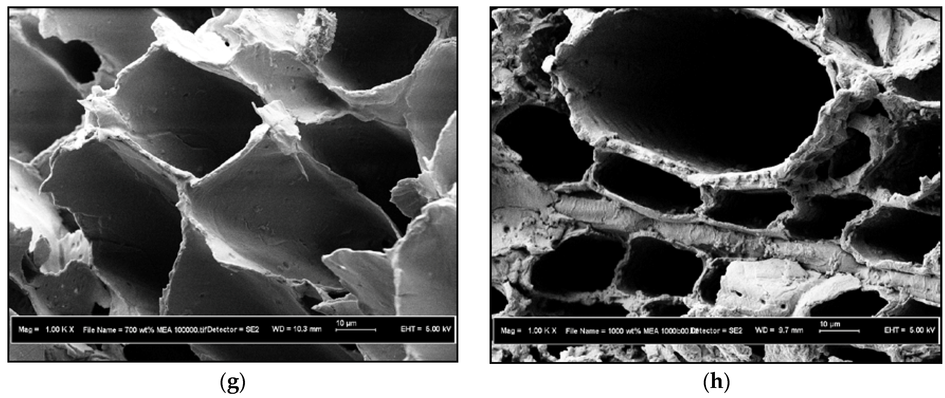
Results presented in Figure 4 also show that the impregnation of TEPA has affected the kenaf structure. Initially, the impregnation of TEPA to kenaf with a ratio of 1:2 produced honeycomb shaped gaps with different pores as represented in Figure 4b. The pore structure of kenaf appeared rough and partially ruptured as the TEPA concentration to kenaf increased to 7:10 (shown in Figure 4c). Further increase of TEPA concentration to a 1:1 ratio yields jagged and serrated pore structures. The larger and robust heterogeneous pore openings developed after the impregnation of TEPA to kenaf with a ratio of 2:1 as shown in Figure 4e. Then, the additional TEPA concentration to kenaf up to a ratio of 10:1 caused some of the heterogeneous pore openings to be larger and formed a destroyed and ruptured structure that might have blocked some of the pore openings of kenaf. The analysis performed via FESEM showed that higher amine concentration impregnated on kenaf could construct a breakable and weak pore structure, which would then be demolished to create larger pore openings. The SEM results provided preliminary knowledge on the prepared adsorbent for the CO2 adsorption process.
3.1.3. EDX Characterization Study
The EDX quantification analysis for each sample was determined by varying the effect of amine concentration from 0.5 up to 10 times the sample weight. The list of elemental compositions of each amine-modified kenaf core sample is summarized in Table 1 and Table 2, respectively. The initial weight of kenaf sample was 1.5g. The amounts of MEA impregnation required were based on the fixed ratio.
The pH value was also g considered on the table in order to measure the level of alkalinity of the prepared sample.
Table 1 and Table 2 tabulate the carbon (C), oxygen (O), and nitrogen (N) compositions contained in the MEA-modified kenaf and TEPA-modified kenaf samples at different amine concentrations. According to the elemental composition data, the amount of nitrogen (N) content in MEA and TEPA modified kenaf sample increased as the amine concentration increased. These results are in good agreement with the study done by Anita et al. [41] who found that the amount of nitrogen content in MEA functionalized Si–MCM–41 increases as the amine loading increases from 10 wt % to 50 wt %. Based on the elemental data shown, the amount of nitrogen content in TEPA-modified kenaf sample was higher than the MEA-modified kenaf sample for each equivalent loading. This is because the TEPA functional group comprises five nitrogen atoms bonded to the main chain, whilst the MEA functional group comprises only one nitrogen atom bonded to the main chain. Besides, TEPA has eight alkyl functional groups as compared to the single alkyl group present in MEA. This would increase the energy of the lone electron pair on nitrogen and improve the basicity character. Based on this chemistry principle, TEPA should present relatively higher basicity characteristic than MEA. In addition, a direct basicity measurement could be done by taking a power of hydrogen (pH) reading for each decanted alcoholic amine solution. Based on the presented pH readings, TEPA-modified kenaf has a higher pH value than MEA-modified kenaf at similar loadings. The pH reading indicates a higher number as the amine concentration increases. The higher pH reading is representative of the higher alkalinity/basicity characteristics of the prepared amine-modified kenaf samples which is also in line with the EDX elemental analysis.
3.2. Effect of Amine Concentration on CO2 Adsorption Study
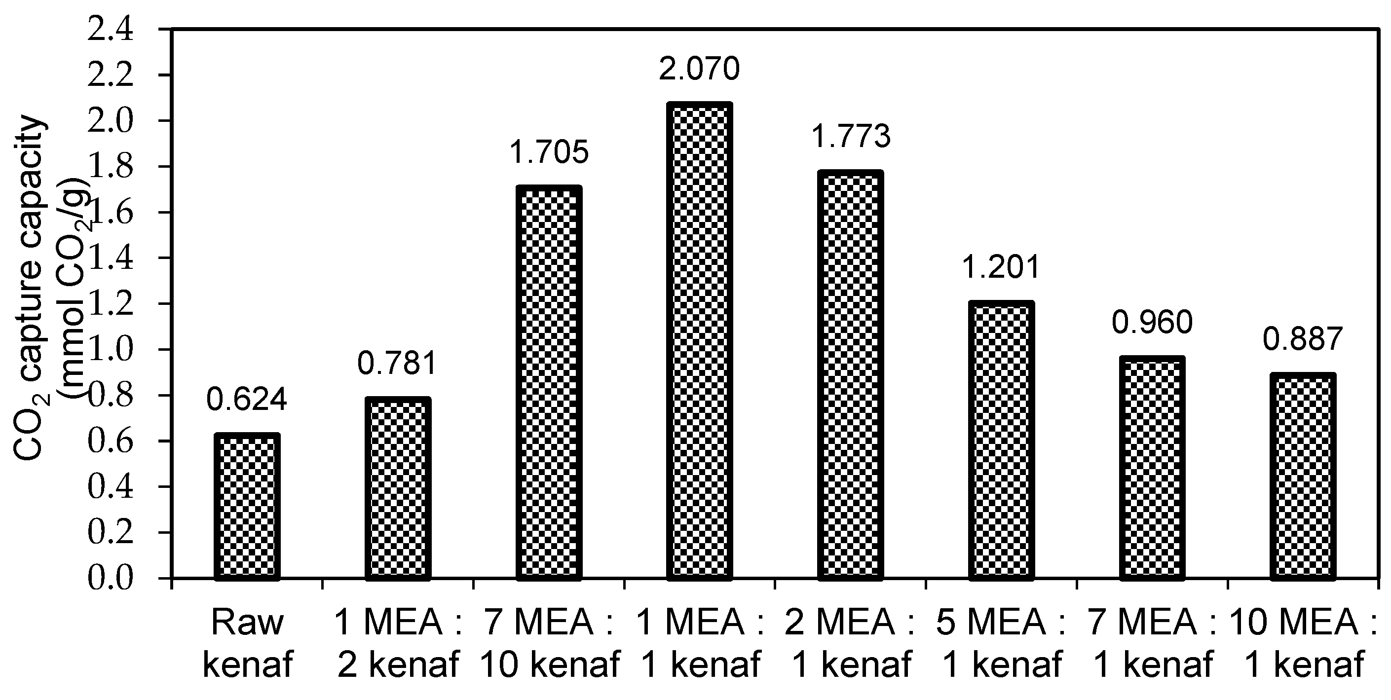
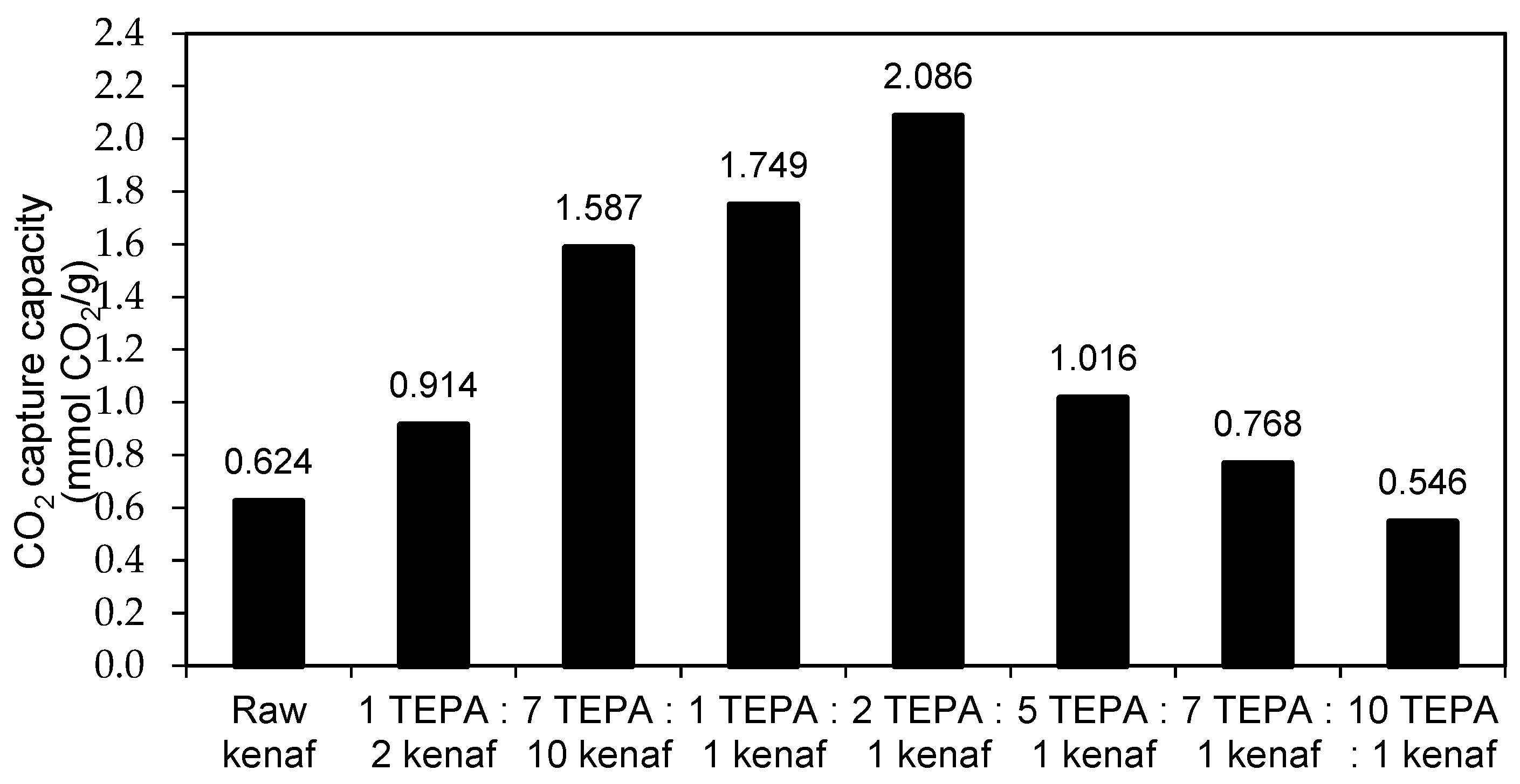
This section discusses the effect of amine concentration on the CO2 adsorption capacity of kenaf. The MEA and TEPA concentrations to kenaf varied in the ratios of 1:2, 7:10, 1:1, 2:1, 5:1, 7:1, and 10:1. Figure 5 and Figure 6 show the CO2 adsorption capacity of samples in pressure swing adsorption (PSA).
Figure 5 and Figure 6 elucidate the effect of different MEA and TEPA concentrations on kenaf. Based on the results, different amine concentrations would result in a different capacity of CO2 adsorption. As represented in Figure 5, the MEA to kenaf ratio of 1:1 has the highest CO2 adsorption capacity (2.070 mmol/g), while TEPA to kenaf at a ratio of 2:1 was able to adsorb the highest amount of CO2 as it achieved as high a value as 2.086 mmol/g in the first cycle. The different capacities of CO2 adsorption for both MEA-modified kenaf and TEPA-modified kenaf samples were due to the availability of adsorption sites. The availability of adsorption sites for MEA-modified kenaf and TEPA-modified kenaf samples are shown in Figure 3 and Figure 4, respectively. In fact, FESEM morphology indicated the effect of amine concentration on the structure of kenaf prior to CO2 adsorption process. It clearly shows that the presence of heterogeneous honeycomb shapes for MEA to kenaf sample at the ratios of 1:2, 7:10, and 1:1 facilitated the interaction of MEA on the kenaf surface with CO2 adsorbates. However, additional MEA to kenaf at the ratios of 2:1, 5:1, 7:1, and 10:1 created heterogeneous pore openings, of which some were partially broken and destroyed. The presence of these partially broken and destroyed pore openings might block the sites available for the amine-gas interaction during the adsorption process leading to the reduction of the CO2 adsorption capacity. In the case of TEPA-modified kenaf adsorbent, the samples of TEPA to kenaf at the ratio of 1:2, 7:10, 1:1, and 2:1 preserved the honeycomb shapes with different pore sizes which provided an appropriate site for the adsorption process. In this case, the higher concentration of amines (up to 2:1 ratio) provided sites for the interaction of CO2 that led to the higher CO2 adsorption process. However, the formation of partially ruptured and broken pore openings of the kenaf structure after the impregnation of TEPA to kenaf at the higher ratio (5:1, 7:1, and 10:1) caused blockages that reduced the available sites from interaction of CO2 adsorbates. It can be concluded that the higher TEPA to kenaf ratio (starting from 5:1 ratio) is not necessary for the CO2 adsorption process. It is also summarized that the presence of a highly porous structure would facilitate the CO2 adsorption process, while destroyed and blocked pore openings may reduce the available sites for the adsorption process.
From the results, it can be revealed that the amine concentration has a significant effect on CO2 adsorption capacity. A higher amine concentration destroyed the kenaf core structure and reduced the available adsorption sites for capturing CO2. However, the lower amount of amine loading on the structure of kenaf may not be sufficient to create the chemical bonds between amine-CO2 during the adsorption process. This also contributes to low CO2 adsorption capacity. Based on this study, it can be inferred that amine-modified kenaf adsorbents present the highest CO2 adsorption capacities at an MEA to kenaf ratio of 1:1 (2.070 mmol CO2/g) and TEPA to kenaf ratio of 2:1 (2.086 mmol CO2/g). This study showed that the amine-functionalized kenaf surface presents a promising candidate for the CO2 adsorption process and can be used as an alternative green-based adsorbent in CO2 adsorption studies.
4. Conclusions
This study introduced kenaf as one of the sustainable green-based adsorbents for CO2 capture. It highlighted the potential of kenaf as a precursor for the amine-impregnation method for CO2 adsorption application. This study revealed that MEA and TEPA impregnated on kenaf surface plays a significant role in the CO2 adsorption process. Results obtained revealed that the highest CO2 adsorption capacities for MEA-modified kenaf and TEPA-modified kenaf were achieved at a ratio of 1:1 (2.070 mmol/g) and 2:1 (2.086 mmol/g), respectively. This study also proved that the concentration of amine impregnated on kenaf affects the CO2 adsorption capacity.
Author Contributions
N.Z. and K.S.N.K. conceived and designed the experiments; N.Z. performed the experiments; N.Z. and K.S.N.K. analyzed the data; N.Z. wrote the paper. N.Z and K.S.N.K checked the final paper.
Acknowledgments
The authors would like to acknowledge and appreciate the financial support provided by the Ministry of Education (MOE) under MyBrain15 (MyPhD) scholarship, and Ministry of Science, Technology and Innovation (MOSTI) for the vote number of 4S047. A special appreciation goes to the National Kenaf and Tobacco Board (NKTB), Kelantan for the material supplied throughout this study.
Conflicts of Interest
The authors declare no conflict of interest.
References
- Yang, H.; Xu, Z.; Fan, M.; Gupta, R.; Slimane, R.B.; Bland, A.E.; Wright, I. Progress in carbon dioxide separation and capture: A review. J. Environ. Sci. 2008, 20, 14–27. [Google Scholar] [CrossRef]
- Zhang, Z.; Xiao, Y.; Wang, B.; Sun, Q.; Liu, H. Waste is a misplayed resource: Synthesis of zeolites from fly ash for CO2 capture. Energy Procedia 2017, 114, 2537–2544. [Google Scholar] [CrossRef]
- Yu, C.H.; Huang, C.H.; Tan, C.S. A review of CO2 capture by absorption and adsorption. Aerosol Air Qual. Res. 2012, 12, 745–769. [Google Scholar] [CrossRef]
- Zhang, Z.; Wang, B.; Sun, Q.; Zheng, L. A novel method for the preparation of CO2 sorption sorbents with high performance. Appl. Energy 2014, 123, 179–184. [Google Scholar] [CrossRef]
- Luca, R.; Olav, B. Overview on pressure swing adsorption (PSA) as CO2 capture technology: State-of-the-art, limits and potentials. Energy Procedia 2017, 114, 2390–2400. [Google Scholar]
- Gray, M.L.; Soong, Y.; Champagne, K.J.; Pennline, H.; Baltrus, J.P.; Stevens, R.W.; Khatri, R.; Chuang, S.S.C.; Filburn, T. Improved immobilized carbon dioxide capture sorbents. Fuel Process. Technol. 2005, 86, 1449–1455. [Google Scholar] [CrossRef]
- Zanganeh, K.E.; Shafeen, A.; Salvador, C. CO2 capture and development of an advanced pilot–scale cryogenic separation and compression unit. Energy Procedia 2009, 1, 247–252. [Google Scholar] [CrossRef]
- Brunetti, A.; Scura, F.; Barbieri, G.; Drioli, E. Membrane technologies for CO2 separation. J. Membr. Sci. 2010, 359, 115–125. [Google Scholar] [CrossRef]
- Resnik, K.P. Aqua ammonia process for simultaneous removal of CO2, SO2 and NOx. Int. J. Environ. Technol. Manag. 2004, 4, 89–104. [Google Scholar] [CrossRef]
- Haszeldine, R.S. Carbon capture and storage: How green can black be? Science 2009, 325, 1647–1652. [Google Scholar] [CrossRef] [PubMed]
- Bara, J.E.; Camper, D.E.; Gin, D.L.; Noble, R.D. Room-temperature ionic liquids and composite materials: Platform technologies for CO2 capture. Acc. Chem. Res. 2010, 43, 152–159. [Google Scholar] [CrossRef] [PubMed]
- Duffy, A.; Walker, G.M.; Allen, S.J. Investigations on the Adsorption of Acidic Gases using Activated Dolomite. Chem. Eng. J. 2006, 117, 239–244. [Google Scholar] [CrossRef]
- Mandal, B.P.; Bandyopadhyay, S.S. Simultaneous absorption of CO2 and H2S into aqueous blends of n–methyldiethanolamine and diethanolamine. Environ. Sci. Technol. 2006, 40, 6076–6084. [Google Scholar] [CrossRef]
- Plaza, M.G.; Pevida, C.; Arenillas, A.; Rubiera, F.; Pis, J.J. CO2 capture by adsorption with nitrogen enriched carbons. Fuel 2007, 86, 2204–2212. [Google Scholar] [CrossRef]
- Serna-Guerrero, R.; Belmabkhkout, Y.; Sayari, A. Influence of regeneration conditions on the cyclic performance of amine-grafted mesoporous silica for CO2 capture: An experimental and statistical study. Chem. Eng. Sci. 2010, 65, 4166–4172. [Google Scholar] [CrossRef]
- Samanta, A.; Zhou, A.; Shimizu, G.K.H.; Sarkar, P.; Gupta, R. Post–combustion CO2 capture using solid sorbents: A review. Ind. Eng. Chem. Res. 2011, 51, 1438–1463. [Google Scholar] [CrossRef]
- Choi, S.; Drese, J.H.; Jones, C.W. Adsorbent materials for carbon dioxide capture from large anthropogenic point sources. Chemsuschem 2009, 2, 796–854. [Google Scholar] [CrossRef] [PubMed]
- Plaza, M.G.; Gonzalez, A.S.; Pevida, C.; Pis, J.J.; Rubiera, F. Valorisation of spent coffee grounds as CO2 adsorbents for post combustion capture applications. Appl. Energy 2012, 99, 272–279. [Google Scholar] [CrossRef]
- González, A.S.; Plaza, M.G.; Rubiera, F.; Pevida, C. Sustainable biomass–based carbon adsorbents for post–combustion CO2 capture. Chem. Eng. J. 2013, 230, 456–465. [Google Scholar] [CrossRef]
- Nasri, N.S.; Hamza, U.D.; Ismail, S.N.; Ahmed, M.M.; Mohsin, R. Assessment of porous carbons derived from sustainable palm solid waste for carbon dioxide capture. J. Clean. Prod. 2013, 71, 148–157. [Google Scholar] [CrossRef]
- Lee, C.S.; Ong, Y.L.; Aroua, M.K.; Daud, W.M.A.W. Impregnation of palm shell based activated carbon with sterically hindered amines for CO2 adsorption. Chem. Eng. J. 2013, 219, 558–564. [Google Scholar] [CrossRef]
- Ello, A.S.; Luiz, K.C.; de Souza, A.T.; Mietek, J. Development of microporous carbons for CO2 capture by KOH activation of african palm shells. J. CO2 Util. 2013, 2, 35–38. [Google Scholar] [CrossRef]
- Vargas, D.P.; Giraldo, L.; Silvestre-Albero, J.; Moreno-Pirajan, J.C. CO2 adsorption on binderless activated carbon monoliths. Adsorption 2011, 17, 497–504. [Google Scholar] [CrossRef]
- Shen, W.; He, Y.; Zhang, S.; Li, J.; Fan, W. Yeast–based microporous carbon material for carbon dioxide capture. ChemSusChem 2012, 5, 1274–1279. [Google Scholar] [CrossRef] [PubMed]
- Qiao, J.; Liu, Y.; Hong, F.; Zhang, J. A review of catalysts for the electroreduction of carbon dioxide to produce low-carbon fuels. Chem. Soc. Rev. 2014, 43, 631–675. [Google Scholar] [CrossRef] [PubMed]
- Song, J.; Shen, W.; Wang, J.; Fan, W. Superior carbon–based CO2 adsorbents prepared from poplar anthers. Carbon 2014, 69, 255–263. [Google Scholar] [CrossRef]
- Boonpoke, A.; Chirakorn, S.; Laosiripojana, N.; Towprayon, S.; Chidthaisong, A. Synthesis of activated carbon and MCM–41 from bagasse and rice husk and their carbon dioxide adsorption capacity. J. Sustain. Energy Environ. 2011, 2, 77–81. [Google Scholar]
- Alhwaige, A.A.; Ishida, H.; Agag, T.; Qutubuddin, S. Biobased chitosan hybrid aerogels with superior adsorption: Role of graphene oxide in CO2 capture. RSC Adv. 2013, 3, 16011–16020. [Google Scholar] [CrossRef]
- Primo, A.; Forneli, A.; Corma, A.; Garci’a, H. From biomass wastes to highly efficient CO2 adsorption: Graphitisation of chitosan and alignates biopolymers. ChemSusChem 2012, 5, 2207–2217. [Google Scholar] [CrossRef] [PubMed]
- Othman, M.R.; Akil, H.M. The CO2 adsorptive and regenerative behaviors of rhizopus oligosporus and carbonaceous hibiscus cannabinus exposed to thermal swings. Microporous Mesoporous Mater. 2008, 110, 363–369. [Google Scholar] [CrossRef]
- Garcia, A.M.; Cuerda-Correa, E.M.; Marin, M.O.; Paralejo, A.D.; Diez, M.A.D. Development and characterization of carbon–honeycomb monoliths from kenaf natural fibers: A preliminary study. Ind. Crops Prod. 2011, 35, 105–110. [Google Scholar] [CrossRef]
- Murphy, P.T.; Moore, K.J.; Richard, T.L.; Bern, C.J. Enzyme enhanced solid-state fermentation of kenaf core fiber for storage and pretreatment. Bioresour. Technol. 2007, 98, 3106–3111. [Google Scholar] [CrossRef] [PubMed]
- Abdul Khalil, H.P.S.; Ireana Yusra, A.F.; Bhat, A.H.; Jawaid, M. Cell wall ultrastructure, anatomy, lignin distribution and chemical composition of malaysian cultivated kenaf fiber. Ind. Crops Prod. 2010, 31, 113–121. [Google Scholar] [CrossRef]
- Siqueira, R.M.; Freitas, G.R.; Peixoto, H.R.; do Nascimento, J.F.; Musse, A.P.S.; Torres, A.E.B.; Azevedo, D.C.S.; Bastos-Neto, M. Carbon dioxide capture by pressure swing adsorption. Energy Procedia 2017, 114, 2182–2192. [Google Scholar] [CrossRef]
- Zaini, N. Amine-Functionalized Kenaf as Carbon Dioxide Adsorbent in Pressure Swing Adsorption System. Ph.D. Thesis, Universiti Teknologi Malaysia, Johor Bahru, Malaysia, 2006. [Google Scholar]
- Khalil, H.P.A.; Ismail, H.; Roazman, H.D.; Ahmad, M.N. The effect of acetylation on interfacial shear strength between plant fiber and various matrices. Eur. Polym. J. 2001, 37, 1037–1045. [Google Scholar] [CrossRef]
- Sgriccia, N.; Hawley, M.; Misra, M. Characterization of natural fiber surfaces and natural fiber composites. Compos. Part A 2008, 39, 1632–1637. [Google Scholar] [CrossRef]
- Jonoobi, M.; Harun, J.; Tahir, P.M.; Zaini, L.H.; Azry, S.S.; Makinejad, M.D. Characteristics of nanofibers extracted from kenaf core. Bioresources 2010, 5, 2556–2566. [Google Scholar]
- Nacos, M.; Katapodis, P.; Pappas, C.; Daferera, D.; Tarantilis, P.A.; Christakopoulos, P.; Polissiou, M. Kenaf xylan–A source of biologically active acidic oligosaccharides. Carbohydr. Polym. 2006, 66, 126–134. [Google Scholar] [CrossRef]
- Troedec, M.; Sedan, D.; Peyratout, C.; Bonnet, J.; Smith, A.; Guinebretiere, R.; Gloaguen, V.; Krausz, P. Influence of various chemical treatments on the composition and structure of hemp fibers. Compos. Part A 2008, 39, 514–522. [Google Scholar] [CrossRef]
- Anita, R.; Sohail, A.; Suzana, Y. Effect of monoethanolamine loading on the physicochemical properties of amine–functionalized Si-MCM-41. Sains Malays. 2014, 43, 253–259. [Google Scholar]
Figure 1.
Schematic diagram of double-column PSA experimental unit.

Figure 2.
IR spectra: (a) raw kenaf core; (b) MEA-modified kenaf; (c) TEPA-modified kenaf.

Figure 3.
FESEM morphology of MEA-modified kenaf samples at different amine to kenaf ratios: (a) raw kenaf core; (b) 1:2; (c) 7:10; (d) 1:1; (e) 2:1; (f) 5:1; (g) 7:1; (h) 10:1.
Figure 3.
FESEM morphology of MEA-modified kenaf samples at different amine to kenaf ratios: (a) raw kenaf core; (b) 1:2; (c) 7:10; (d) 1:1; (e) 2:1; (f) 5:1; (g) 7:1; (h) 10:1.


Figure 4.
FESEM morphology of TEPA-modified kenaf samples at different amine to kenaf ratios: (a) raw kenaf core; (b) 1:2; (c) 7:10; (d) 1:1; (e) 2:1; (f) 5:1; (g) 7:1; (h) 10:1.
Figure 4.
FESEM morphology of TEPA-modified kenaf samples at different amine to kenaf ratios: (a) raw kenaf core; (b) 1:2; (c) 7:10; (d) 1:1; (e) 2:1; (f) 5:1; (g) 7:1; (h) 10:1.


Figure 5.
CO2 adsorption capacity of MEA-modified kenaf at different concentrations.

Figure 6.
CO2 adsorption capacity of TEPA-modified kenaf at different concentrations.


Table 1.
Elemental composition data for MEA-modified kenaf sample at different concentrations.
| Ratio MEA:Kenaf | Amount of MEA Needed (g) | Elemental Compositions (wt %) | pH Value | ||
|---|---|---|---|---|---|
| Carbon (C) | Oxygen (O) | Nitrogen (N) | |||
| 1:2 | 0.75 | 55.51 | 42.16 | 2.34 | 10.60 |
| 7:10 | 1.05 | 57.59 | 39.44 | 2.98 | 10.62 |
| 1:1 | 1.50 | 60.40 | 32.40 | 7.20 | 10.81 |
| 2:1 | 3.00 | 54.22 | 37.51 | 8.27 | 11.15 |
| 5:1 | 7.50 | 60.27 | 30.56 | 9.17 | 11.27 |
| 7:1 | 10.50 | 51.88 | 38.11 | 10.02 | 11.38 |
| 10:1 | 15.00 | 50.96 | 38.02 | 11.02 | 11.67 |
Table 2.
Elemental composition data for TEPA-modified kenaf sample at different concentrations.
| Ratio TEPA:Kenaf | Amount of TEPA Needed (g) | Elemental Compositions (wt %) | pH Value | ||
|---|---|---|---|---|---|
| Carbon (C) | Oxygen (O) | Nitrogen (N) | |||
| 1:2 | 0.75 | 63.52 | 29.09 | 7.39 | 10.82 |
| 7:10 | 1.05 | 57.27 | 35.09 | 7.65 | 11.02 |
| 1:1 | 1.50 | 56.89 | 34.72 | 8.39 | 11.14 |
| 2:1 | 3.00 | 54.51 | 33.08 | 12.41 | 11.39 |
| 5:1 | 7.50 | 51.55 | 32.99 | 15.46 | 11.83 |
| 7:1 | 10.50 | 51.90 | 29.84 | 18.27 | 12.01 |
| 10:1 | 15.00 | 48.15 | 31.94 | 19.91 | 12.05 |
© 2018 by the authors. Licensee MDPI, Basel, Switzerland. This article is an open access article distributed under the terms and conditions of the Creative Commons Attribution (CC BY) license (http://creativecommons.org/licenses/by/4.0/).
Share and Cite
MDPI and ACS Style
Zaini, N.; Kamarudin, K.S.N. Effect of Concentration on Amine-Modified Kenaf as a Sorbent for Carbon Dioxide Adsorption in a Pressure Swing Adsorption System. ChemEngineering 2018, 2, 23. https://doi.org/10.3390/chemengineering2020023
AMA Style
Zaini N, Kamarudin KSN. Effect of Concentration on Amine-Modified Kenaf as a Sorbent for Carbon Dioxide Adsorption in a Pressure Swing Adsorption System. ChemEngineering. 2018; 2(2):23. https://doi.org/10.3390/chemengineering2020023
Chicago/Turabian StyleZaini, Nabilah, and Khairul Sozana Nor Kamarudin. 2018. "Effect of Concentration on Amine-Modified Kenaf as a Sorbent for Carbon Dioxide Adsorption in a Pressure Swing Adsorption System" ChemEngineering 2, no. 2: 23. https://doi.org/10.3390/chemengineering2020023