
Laser-Induced Motion of a Nanofluid in a Micro-Channel

National Energy Technology Laboratory, U.S. Department of Energy, P.O. Box 10940, Pittsburgh, PA 15236, USA
*
Author to whom correspondence should be addressed.
Fluids 2016, 1(4), 35; https://doi.org/10.3390/fluids1040035
Submission received: 29 August 2016
/
Revised: 7 October 2016
/
Accepted: 21 October 2016
/
Published: 26 October 2016
(This article belongs to the Special Issue Fundamental Studies in Flow and Heat Transfer in Nanofluids)
Abstract
:Since a photon carries both energy and momentum, when it interacts with a particle, photon-particle energy and momentum transfer occur, resulting in mechanical forces acting on the particle. In this paper we report our theoretical study on the use of a laser beam to manipulate and control the flow of nanofluids in a micro-channel. We calculate the velocity induced by a laser beam for TiO2, Fe2O3, Al2O3 MgO, and SiO2 nanoparticles with water as the base fluid. The particle diameter is 50 nm and the laser beam is a 4 W continuous beam of 6 mm diameter and 532 nm wavelength. The results indicate that, as the particle moves, a significant volume of the surrounding water (up to about 8 particle diameters away from the particle surface) is disturbed and dragged along with the moving particle. The results also show the effect of the particle refractive index on the particle velocity and the induced volume flow rate. The velocity and the volume flowrate induced by the TiO2 nanoparticle (refractive index n = 2.82) are about 0.552 mm/s and 9.86 fL, respectively, while those induced by SiO2 (n = 1.46) are only about 7.569 μm/s and 0.135, respectively.
1. Introduction
Micro-channels are devices that are used to transport, process, and manipulate extremely small volumes of fluids ranging from 10−15 m3 to 10−6 m3. Such devices have been found to be of significant importance in a variety of technologies such as cooling of electronic chips, inkjet printers, drug delivery, biomedical diagnostics, and biochemical processing, etc.
Generally, transporting fluids (or nanofluids) in micro-sized devices is achieved by a pumping mechanism that can be generated either by an external mechanical pumping system or non-mechanical pumping techniques using electro-osmosis [1,2,3], electrophoresis [4], electromagnetics [5], electrowetting [6,7], etc. There are some drawbacks associated with the use of a conventional mechanical pump because it has many components that are typically large relative to the small dimensions of microchannels. Although micropumps that are able to provide sufficient pumping power are available, the small size of the moving parts makes them difficult to fabricate and maintain. Non-mechanical pumping techniques have many disadvantages. For example, a device that utilizes electro-osmosis needs to be electronically reconfigured in order to maintain an electric field of about 30 KV/m; this is high enough to electrolyze the water base generating hydrogen peroxide, hydrogen ions (acid) and hydroxide (base) as well as oxygen and hydrogen gas bubbles. The hydrogen peroxide and/or pH changes generated can adversely affect biological cells and biomolecules such as proteins, while the generated gas bubbles tend to “clog” the microfluidic systems.
In this paper, we explore the use of a laser beam to manipulate and control the flow of nanofluids in micro-scaled devices. The concept is based on the fact that, when a nanofluid is irradiated by a laser beam, if the fluid base is transparent to the laser beam, interactions between the laser beam and the suspended nanoparticles via reflection, transmission, and absorption occur. Since the laser beam carries both energy and momentum, such interactions create (mechanical) forces acting on the suspended particles. If the particles are absorptive, they are heated and temperature gradients on their surfaces prevail. The surrounding gas molecules are heated unevenly and rebound off the particles at different velocities, resulting in a force called photophoretic force acting on the particles. If the particles are non-absorptive, the momentum transfer during refraction and reflection of the photon become dominant. In this case, the resulting force is called the pressure force which is composed of two components: the gradient component acts transversely and the scattering (axial) component acts in the direction of the laser propagation. Thus, the particles will be pulled into the higher intensity region of the beam in the transverse direction by the gradient component of the force, and they will be simultaneously pushed along in the direction of the beam propagation by the scattering component. As the particles move they disturb and drag the surrounding fluid with them. As a result, a flow field, as shown in Figure 1, is generated.
Use of a laser beam to induce and manipulate the motion of micron/nano-size particles has been reported previously [8,9,10,11,12,13,14,15,16]. In these studies, laser-induced motion of transparent particles such as glass, silica, Poly(methyl methacrylate) (PMMA), polystyrene, nickel and aluminum oxides particles in water using a loosely focused Gaussian beam were investigated. The effects of various parameters including numerical aperture, focal length, laser power, particle size, refractive index, and medium velocity on the parting distance, and the number of particles separated per unit time were studied. Phuoc et al. [16] also reported a study on the laser-induced motion and the travel distances of some rare earth and mineral oxides that are commonly found in coal ashes. Their results indicated that, under laser action, these oxide particles were moving in the direction of the laser propagation and finally dropped out of the laser beam into two small areas that were several millimeters apart. The rare earth oxides were seen to concentrate in the area near the beam waist while the mineral oxides were mainly concentrated in the area further away from the beam waist.
In order to demonstrate that the flow of a nanofluid in a micro-channel can be controlled by a laser beam, we present some preliminary results on the particle velocity and its impact on the surrounding fluid in terms of its velocity and the flowrate. The calculations are carried out for five typical nanoparticles (TiO2, Fe2O3, Al2O3∙MgO, and SiO2) with water as the liquid medium. We use these typical particles because they are commonly used as the solid component in many nanofluids.
2. Forces Acting on a Single Particle
Tchen [17] synthesizes the work of Basset, Boussinesq, Stokes, and Oseen on the motion of a sphere settling under the force of gravity in a fluid at rest. The resulting force balance, sometimes known as the Basset-Boussinesq-Oseen (BBO) equation, is given by:
where u is the velocity of the particle, and are density of the fluid and particle, respectively, a is the particle radius, g is the acceleration of gravity, and are viscosity and kinematic viscosity of the fluid, respectively. The terms on the right-hand side of the above equation are related to the virtual mass effects, Stokes drag, Basset history effects, and buoyancy. Maxey and Riley [18], proposed a generalization of the above equation for the forces acting on a sphere in a nonuniform flow:
The terms involving correspond to the physical effect known as the Faxen forces. Although Equation (2) appears to be complete for a single particle in Stokes flow, there are, in general, other forces that must be considered (even for a purely mechanical system). For example, the spin of the particle is not taken into account in the above equations (see Massoudi [19,20]).
Briefly, the linear momentum equation for a single particle, using the vector notation is:
where is the density, u is the velocity vector, b the body force, and . represent the various forces acting on the particle which can include the terms on the right hand side of Equation (2) and also forces due to the electric current, magnetic field interactions (see Kim et al. [21]), and the radiation due to the laser, etc. In this paper, we ignore all the forces except that due to the laser. In the next section we discuss this force.
3. Forces Due to the Laser
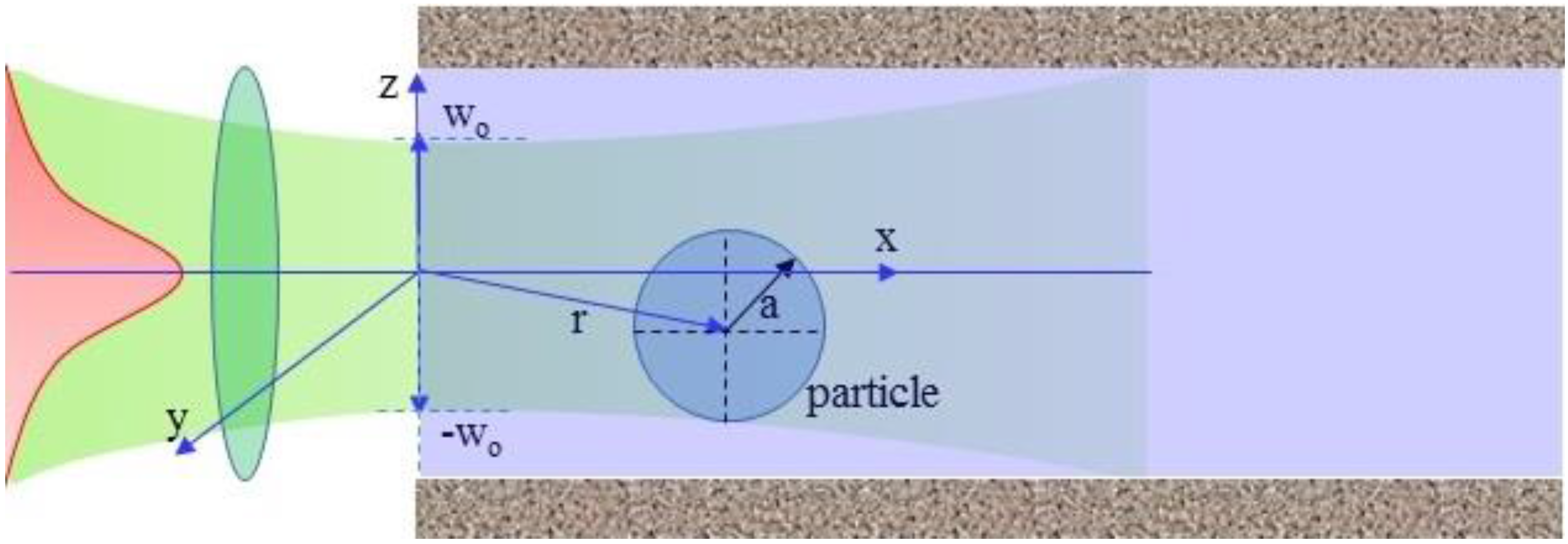
Here we consider the interaction between a CW Gaussian beam and a nanofluid (See Figure 2). The laser beam is slightly focused with a beam waist 2wo at the focal point located at x = 0. Its wavelength λ is very long compared to the suspended particle size and it is chosen so that the fluid base with the refractive index nf is transparent to it. The suspended nanoparticle of radius a is considered to be non-absorptive relative to the laser wavelength and it is located at a position r = (x, y, z) relative to the beam waist center. The particle refractive index is np. Since the particle is non-absorptive, the momentum transfer during refraction and reflection of the photon becomes dominant. In this case, the resulting forces are the scattering force, Fsctr, and the force due to the gradient of intensity, often called the gradient force. The scattering force acts in the direction of the photon propagation. In contrast, the gradient force has, in a Cartesian coordinate system, three components: two transverse components (Fgrad,y, and Fgrad,z) which act to restore the particle to the beam center and a longitudinal component, Fgrad,x which acts against the scattering force to pull the particle toward the beam waist. Since the size of the nano-particle is very small compared to the wavelength of the laser beam, these forces are in the Rayleigh scattering regime and they are given as [22,23]:
The scattering force
The gradient force components
where k = 2π/λ is the wave number, λ is the beam wavelength, c is the beam speed, a is the particle radius, m = np/nf is the particle relative refractive index, Po is the beam power, wo is the beam waist, and are the dimensionless coordinates. If the focal region of the beam is assumed to be cylindrical in shape, the focal spot size, in terms of the beam waist wo is given as
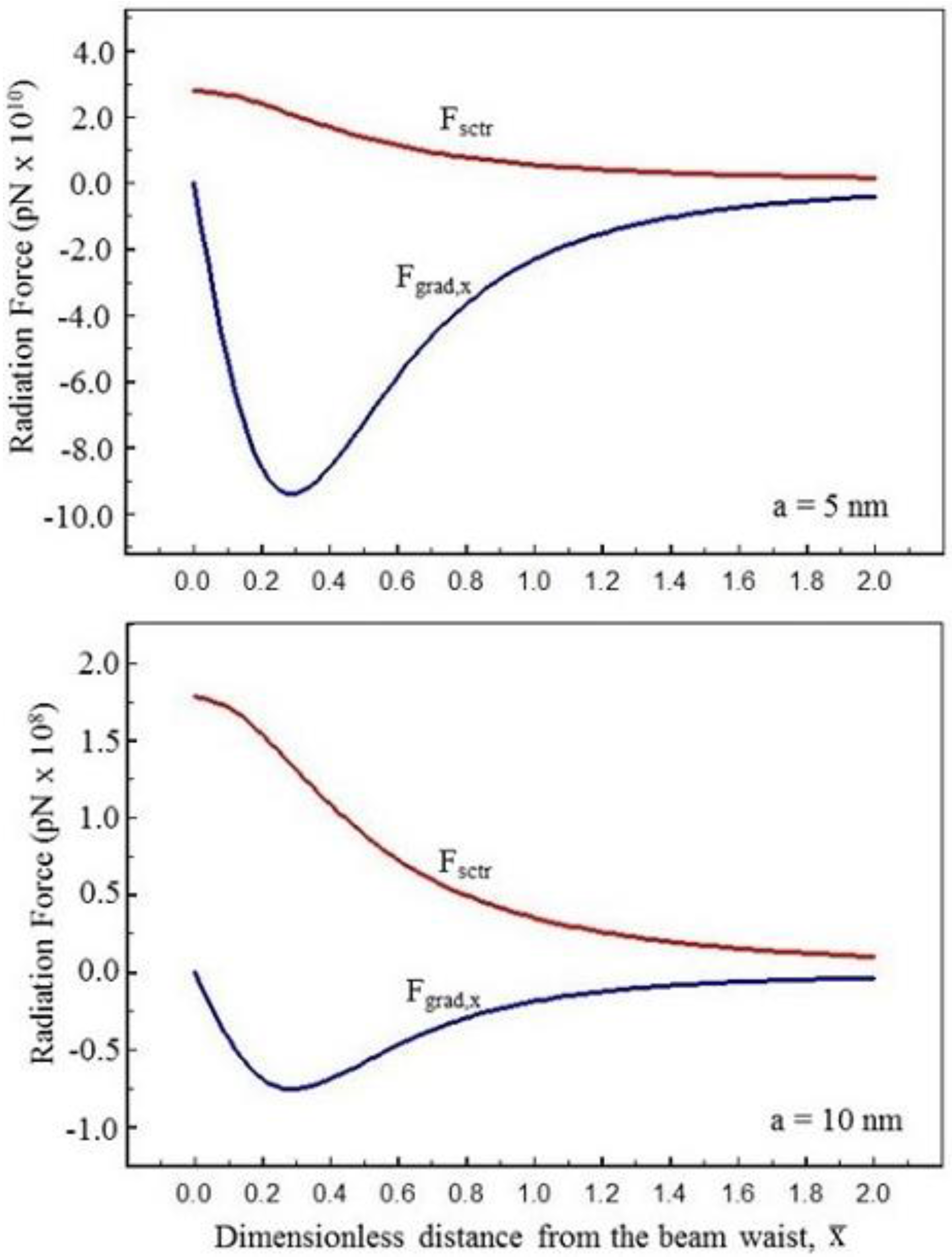
From the system of forces given above, we can see that the particles having m > 1 at any location of the beam center will be quickly attracted to the beam center due to the transvers components Fgrad,y and Fgrad,z where they are pushed along the direction of the beam propagation or pulled back to the beam waist depending on the magnitudes of the scattering force and the longitudinal component of the gradient force. The magnitudes of these forces depend significantly on the particle size, as shown in Figure 3.
In Figure 3 the radiation forces acting on a particle located at the beam center are presented. Since the particle is at the beam center, the force components Fgrad,y and Fgrad,z are zero and the remaining non-zero forces are the longitudinal component of the force due to the gradient of intensity, Fgrad,x and the scattering force, Fscat. The longitudinal component Fgrad,x is acting toward the beam waist, and its magnitude increases negatively from zero at the beam waist to a maximum value at () away from the beam waist. The scattering force is acting along the direction of the propagation of the laser beam. Its magnitude has a maximum value at the beam waist and decreases rapidly as the particle location moves in the direction of the laser propagation. For the particle sizes shown here, the longitudinal component of the gradient force is significantly larger than the scattering force for the particle size of ≤5 nm and it becomes less significant for the particle sizes larger than 10 nm. Thus, smaller particles are pulled back to the beam waist and the larger particles are pushed along the laser beam. Therefore, in order to induce the flow of a nanofluid in a micro-channel by a laser beam, the nanofluid must contain nanoparticles whose sizes are determined by the ratio of the scattering force Fsctr to the maximum backward longitudinal component of the gradient force. For a Gaussian beam of wavelength λ, a focal spot size wo, the maximum longitudinal component of the gradient force occurs at y = z = 0 and where this ratio becomes
If R > 1, the magnitude of Fsctr is greater than that of Fgrad,x. Thus, the required particle size to move in the direction of the laser propagation is
Under the action of the laser beam, if the particle size satisfies condition (12), the particle will move in the direction of the laser propagation against the surrounding fluid. If we assume that the resisting force by the fluid on the moving particle is described by the Stokes law, then the particle velocity can be calculated using
As the particle moves, the fluid surrounding it begins to move, with the streamlines represented in Figure 1 and the motion is given by [24] using the spherical coordinate system
where is the stream function. The corresponding velocity components of such a flow (Stokes flow) are given by
It is clear that the induced flow due to a moving particle can extend to a large distance away from the particle where the flow velocity approaches zero. As a result, for many general flow situations such as flow in pipes and channels, and where many particles are present, the motion can be modified significantly.
4. Results
We have carried out calculations for five typical nanoparticle materials. The fluid base is water with a refractive index of nf = 1.332 and viscosity μf = 0.98 × 10⁻³ kg/m-s. The particle velocity is calculated using Equation (11) with Fsctr and Fgrad,x given by Equations (4) and (5), respectively. Referring to Figure 1, the velocity profile of the surrounding water, vx (in the direction of the particle motion), across the flow field is calculated from the velocity field described by Equations (13) and (14). The flowrate due to the motion of the particle is where . We use the Simpson’s 1/3 rule to calculate its value from θ = 0 to θ where vx → 0. Typical results for the axial forces, the particles velocities, and the flowrate are shown in Table 1.
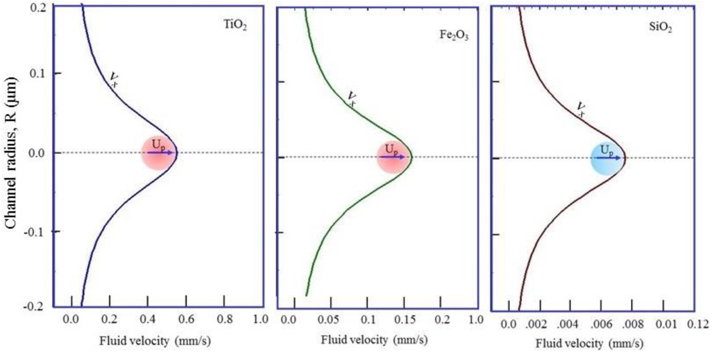
Velocity profiles for flow of water induced by the motion of TiO2 nanoparticle, Fe2O3 nanoparticle, and SiO2 nanoparticle are shown in Figure 4.
It is clear that, as the particle moves, a significant portion of the surrounding water is disturbed and dragged along with the moving particle. On the particle surface, the velocity of the water is equal to that of the moving particle (no-slip condition) and it decreases quickly to zero at a distance of about 8 particle diameters away from the particle surface. The results reported here indicate the significant effect of the particle refractive index on the radiation force and the particle velocity. For example, with the laser power and the optical configuration used in this work, the velocity and the flowrate induced by TiO2 nanoparticle, (refractive index n = 2.82), are about 0.552 mm/s and 9.86 fL, respectively, while those of SiO2 (n = 1.46) are only about 7.569 μm/s and 0.135, respectively. Thus, using a laser beam to activate the flow of a nanofluid in a microchannel is more effective if the fluid contains high refractive index nanoparticles.
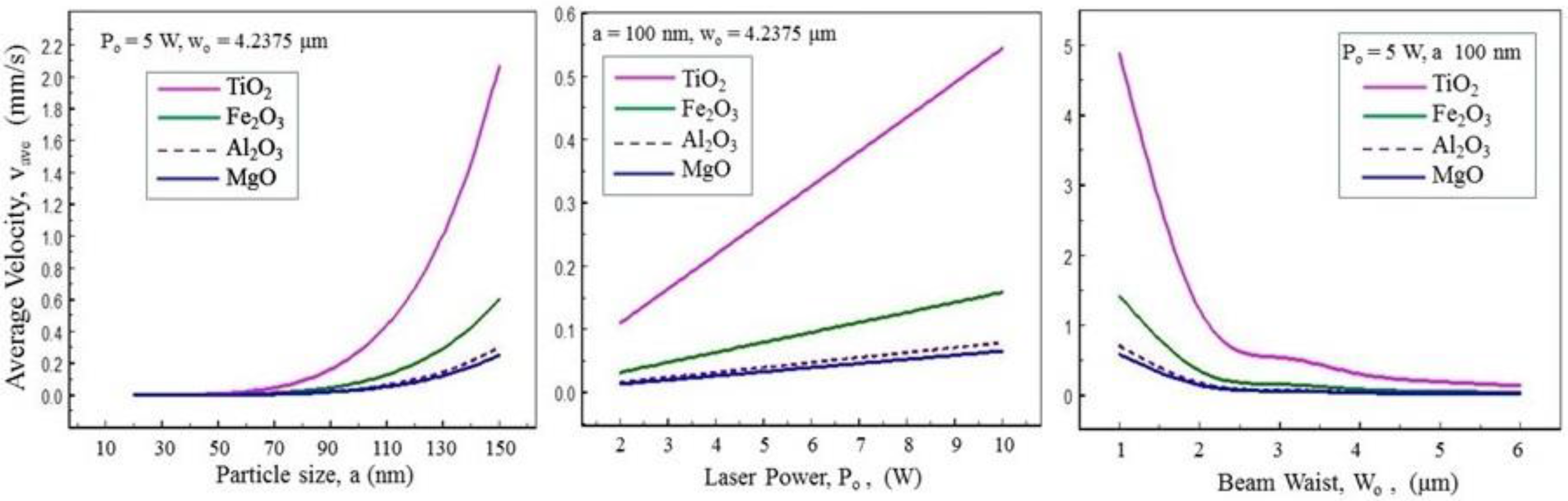
We have also performed a parametric study showing the effects of the laser conditions and particle size on the flowrate and the average velocity induced by the motion of TiO2, Fe2O3, Al2O2, and MgO nanoparticles; these are shown in Figure 5 and Figure 6, respectively. With the typical conditions used here, the results show that a volume up to 4 × 10⁻¹¹ L/s could be transported which depends significantly on the laser power, the particle size, and the beam waist. The effects of these parameters on the fluid average velocity can be seen in Figure 6. To consider the electroosmotic effect on the velocities Sinton and Li [25] and Sinton et al. [26] showed that velocities increased in a linear fashion in 100 μm and 200 μm diameter circular channels and in 100 μm and 50 μm width square channels from about 0.2 mm/s when the external applied field was 5 kV/m; whereas the velocity was 1.2 mm/s when the external applied field was 20 kV/m. A similar velocity range is also obtained in our present calculations for TiO2 and Fe2O3 particles. For example, for a 5 W laser power the fluid average velocity increases up to about 2.1 mm/s with a 150 nm particle while for the same laser power with a 1 μm beam waist, the velocity is about 5 mm/s for a 100 nm particle. However, for Al2O3 and MgO particles, due to their low refractive indexes, the average velocity up to 0.5 mm/s is calculated.
The parametric calculations presented here indicate that the particle refractive index, size, the laser power, and the laser beam waist are the important parameters that can be used to induce and control the flow in microchannels. Use of either high laser power or large particles for delivering high volume of fluid, however, is not of practical interest, since the high laser power can cause significant particle heating which, in turn, can vaporize or alter the integrity of the surrounding fluid. Most conventional nanofluids contain nanoparticles with sizes of 50 nm or less, and using larger particles will lead to other problems associated with the stability of the nanofluid. Thus, we can see that the remaining parameter that can be of practical importance is the beam waist. A beam delivery optics system can be designed to deliver the laser beam via a network of micro-sized fiber optics. In this case, even with a micro watts laser beam, the laser intensity at the output end of the fiber optics will be sufficient for many practical applications.
5. Conclusions
Our simple calculations presented here show that, under the action of a laser, a nanoparticle suspended in a fluid will move and drag a sizable volume of the fluid with it in the direction of the laser propagation. Thus, using a laser beam to manipulate the flow of a nanofluid in a microchannel is possible and it has many advantages over other conventional methods. Such advantages are deduced from the fact that there are no moving parts and no external pumps, which are required, and that there is no need to electronically reconfigure the channel. Additionally, using a fiberoptic cable, the laser beam can be distributed and delivered to multiple micro-channels which can be operated either sequentially or simultaneously. The location of the beam waist can be varied and thus the flow can be initiated at different locations throughout the micro-channel.
Author Contributions
Tran X. Phuoc and Mehrdad Massoudi conceived and developed the model. Tran X. Phuoc did the numeric. And all authors, Tran X. Phuoc, Mehrdad Massoudi, and Ping Wang contributed to the writing and editing of the manuscript.
Conflicts of Interest
The authors declare no conflict of interest.
References
- Buie, C.R.; Kim, D.; Litster, S.; Santiago, J.G. An electro-osmotic fuel pump for direct methanol fuel cells. Electrochem. Solid-State Lett. 2007, 10, B196–B200. [Google Scholar] [CrossRef]
- Wu, J. AC electro-osmotic micropump by asymmetric electrode polarization. J. Appl. Phys. 2008, 103, 024907. [Google Scholar] [CrossRef]
- Chakraborty, S.; Roy, S. Thermally developing electroosmotic transport of nanofluids in microchannels. Microfluid. Nanofluid. 2008, 4, 501–511. [Google Scholar] [CrossRef]
- Huang, W.-H.; Ai, F.; Wang, Z.-L.; Cheng, J.-K. Recent advances in single-cell analysis using capillary electrophoresis and microfluidic device. Chromatography B 2008, 866, 104–122. [Google Scholar] [CrossRef] [PubMed]
- Pamme, N. Magnetism and microfluidics. Lab Chip 2006, 6, 24–38. [Google Scholar] [CrossRef] [PubMed]
- Mugele, F.; Baret, C.J. Electrowetting from basics to applications. J. Phys. Condens. Matter 2005, 17, R705–R774. [Google Scholar] [CrossRef]
- Moon, H.; Cho, S.K.; Garrell, R.L.; Kim, C.-J. Low voltage electrowetting-on-dielectric. J. Appl. Phys. 2002, 92, 4080–4087. [Google Scholar] [CrossRef]
- Koyanaka, S.; Endoh, S. The effect of relative refractive index on monosized particle movement under laser radiation pressure. Adv. Powder Technol. 1999, 10, 205–222. [Google Scholar] [CrossRef]
- Koyanaka, S.; Endoh, S. Numerical simulation of the optical system and medium flow field suitable for particle separation using laser radiation pressure. Adv. Powder Technol. 2004, 15, 321–336. [Google Scholar] [CrossRef]
- Koyanaka, S.; Endoh, S. Effect of laser scanning on increase of throughput in particle separation using laser radiation pressure. Adv. Powder Technol. 2004, 15, 337–349. [Google Scholar] [CrossRef]
- Zhao, B.S.; Koo, Y.M.; Chung, D.S. Separations based on the mechanical forces of light. Anal. Chim. Acta 2006, 556, 97–103. [Google Scholar] [CrossRef] [PubMed]
- Koyanaka, S.; Endoh, S. Three-dimensional analysis of the movement of various micron-sized particles under laser radiation pressure. Powder Technol. 2013, 116, 13–22. [Google Scholar] [CrossRef]
- Lall, A.A.; Terray, A.; Hart, S.J. On-the-fly cross flow laser guided separation of aerosol particles based on size, refractive index and density–theoretical analysis. Opt. Express 2010, 18, 26775–26790. [Google Scholar] [CrossRef] [PubMed]
- Zabetian, M.; Saidi, M.S.; Shafii, M.B.; Saidi, M.H. Separation of microparticles suspended in a minichannel using laser radiation pressure. Appl. Opt. 2013, 52, 4950–4958. [Google Scholar] [CrossRef] [PubMed]
- Xin, H.; Bao, D.; Zhong, F.; Li, B. Photophoretic separation of particles using two tapered optical fibers. Laser Phys. Lett. 2013, 10, 036004. [Google Scholar] [CrossRef]
- Phuoc, T.X.; Wang, P.; McIntyre, D. Discovering the feasibility of using the radiation forces for recovering rare earth elements from coal power plant by-products. Adv. Powder Technol. 2015, 26, 1465–1472. [Google Scholar] [CrossRef]
- Tchen, C.M. Mean Value and Correlation Problems Connected with the Motion of Small Particles Suspended in a Turbulent Fluid; Martinus Nijhoff: The Hague, The Netherlands, 1947. [Google Scholar]
- Maxey, M.R.; Riley, J.J. Equation of motion for a small rigid sphere in a nonuniform flow. Phys. Fluids 1983, 26, 883. [Google Scholar] [CrossRef]
- Massoudi, M. On the importance of material frame-indifference and lift forces in multiphase flows. Chem. Eng. Sci. 2002, 57, 3687–3701. [Google Scholar] [CrossRef]
- Massoudi, M. Constitutive relations for the interaction force in multicomponent particulate flows. Int. J. Non-Linear Mech. 2003, 38, 313–336. [Google Scholar] [CrossRef]
- Kim, J.; Massoudi, M.; Antaki, J.F.; Gandini, A. Removal of malaria-infected red blood cells using magnetic cell separators: A computational study. Appl. Math. Comput. 2012, 218, 6841–6850. [Google Scholar] [CrossRef] [PubMed]
- Harada, Y.; Asakura, T. Radiation forces on a dielectric sphere in the Rayleigh scattering regime. Opt. Commun. 1996, 124, 529–541. [Google Scholar] [CrossRef]
- Zemanek, P.; Jonas, A.; Sramek, L.; Liska, M. Optical trapping of Rayleigh particles using a Haussian standing wave. Opt. Commun. 1988, 151, 273–285. [Google Scholar] [CrossRef]
- Batchelor, G.K. An Introduction to Fluid Dynamics; Cambridge University Press: Cambridge, UK, 2000. [Google Scholar]
- Sinton, D.; Li, D. Electroosmotic velocity profiles in microchannels. Colloids Surface A Physicochem. Eng. Asp. 2003, 222, 273–283. [Google Scholar] [CrossRef]
- Sinton, D.; Escobedo-Canseco, C.; Ren, L.; Li, D. Direct and indirect electroosmotic flow velocity measurements in microchannels. J. Colloids Surf. Sci. 2002, 254, 184–189. [Google Scholar] [CrossRef]
Figure 1.
Representation of the streamlines and the x-component velocity, vx (velocity along with the direction of the particle motion) for flow of the surrounding fluid due to the moving particle, r, θ, are the spherical coordinates of the surrounding fluid described by Equations (13) and (14), U: particle velocity, x: particle flow direction, R: radius of the flow channel relative to the centerline.
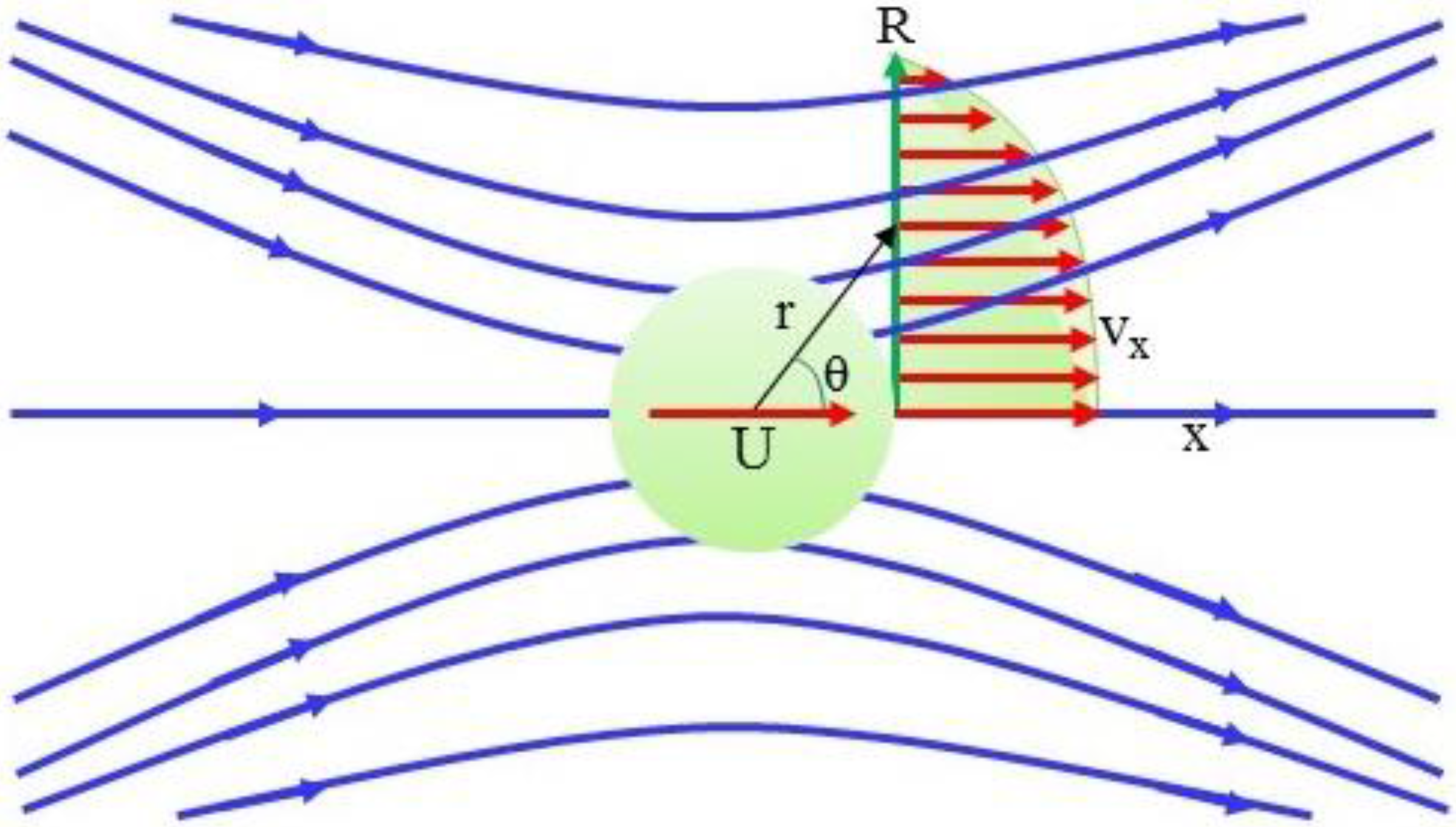
Figure 2.
Representation of the interaction between a Gaussian continuous laser beam and a nanofluid in a micro-channel. The laser beam is slightly focused using a focusing lens, wo is half of the beam waist which is at the channel entrance (x = 0), a is the particle radius, r is the location of the particle relative to center of the beam waist.

Figure 3.
Scattering force, Fsctr and the longitudinal component of the gradient force Fgrad,x as a function of the dimensionless acting on a particle in water located on the beam center , np = 1.592, nf = 1.332, Po = 100 mW, lens focal length f = 75 mm, beam diameter D = 4 mm, wavelength λ= 532 nm.

Figure 4.
Velocity profiles in axial plane of the flow of water induced by the moving particle (Po = 4 W, focal length = 75 mm, beam diameter d = 6 mm, λ = 532 nm, nm (wo = 4.2375 μm, Equation (8)), refractive index of water nf = 1.332, water viscosity μf = 0.98 × 10⁻³ kg/m-s, a = 50 nm, the particle is at the beam waist).

Figure 5.
Effects of the laser power, Po, beam waist, Wo, and particle size on the fluid volume flowrate (focal length = 75 mm, beam diameter d = 6 mm, λ = 532 nm, nm (wo = 4.2375 μm, Equation (8)), refractive index of water nf = 1.332, water viscosity μf =0.98 × 10⁻³ kg/m-s, the particle is at the beam waist).
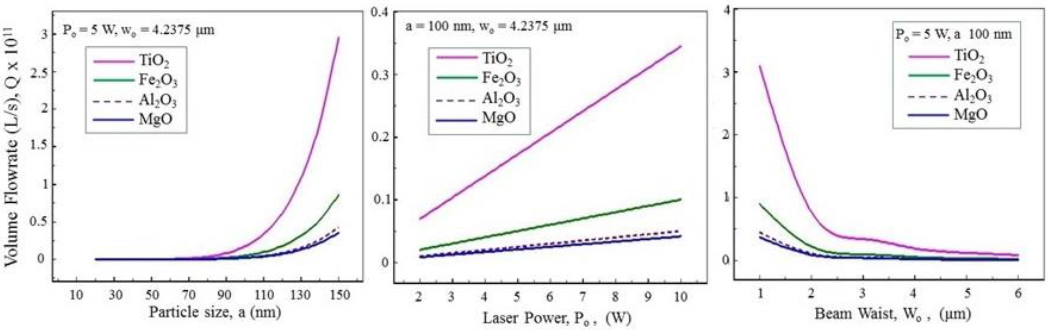
Figure 6.
Effects of the laser power, Po, beam waist, Wo, and particle size on the fluid average velocity (focal length = 75 mm, beam diameter d = 6 mm, λ = 532 nm (wo = 4.2375 μm, Equation (8)), refractive index of water nf = 1.332, water viscosity μf = 0.98 × 10⁻³ kg/m-s, the particle is at the beam waist).

Table 1.
Typical axial forces, particle velocities, and volume flowrate transported by nanoparticles under laser action, (Po = 4 W, focal length = 75 mm, beam diameter d = 6 mm, λ = 532 nm, refractive index of water nf = 1.332, water viscosity μf =0.98 x 10⁻³ kg/m-s, a = 50 nm, the particle is at the beam waist, vp: particle velocity, vf,ave: fluid average velocity, Q: fluid volume flowrate).
| Particle | Refractive Index | Fx(pN) | vp(mm/s) | Q(fl/s) | vf,ave(mm/s) |
|---|---|---|---|---|---|
| TiO2 | 2.82 | 0.4628 | 0.55182 | 9.86 | 0.009 |
| Fe2O3 | 1.986 | 0.1345 | 0.16039 | 2.867 | 0.0028 |
| Al2O3 | 1.773 | 0.0671 | 0.08006 | 1.431 | 0.0014 |
| MgO | 1.73 | 0.0557 | 0.06637 | 1.186 | 0.0015 |
| SiO2 | 1.46 | 0.00635 | 0.007569 | 0.135 | 0.00013 |
© 2016 by the authors; licensee MDPI, Basel, Switzerland. This article is an open access article distributed under the terms and conditions of the Creative Commons Attribution license ( http://creativecommons.org/licenses/by/4.0/).
Share and Cite
MDPI and ACS Style
Phuoc, T.X.; Massoudi, M.; Wang, P. Laser-Induced Motion of a Nanofluid in a Micro-Channel. Fluids 2016, 1, 35. https://doi.org/10.3390/fluids1040035
AMA Style
Phuoc TX, Massoudi M, Wang P. Laser-Induced Motion of a Nanofluid in a Micro-Channel. Fluids. 2016; 1(4):35. https://doi.org/10.3390/fluids1040035
Chicago/Turabian StylePhuoc, Tran X., Mehrdad Massoudi, and Ping Wang. 2016. "Laser-Induced Motion of a Nanofluid in a Micro-Channel" Fluids 1, no. 4: 35. https://doi.org/10.3390/fluids1040035