Relative Effects of Asymmetry and Wall Slip on the Stability of Plane Channel Flow

1
NPCU, Faculty of Sciences, Université Libre de Bruxelles, 1050 Bruxelles, Belgium
2
Department of Mathematics, SRM Research Institute, SRM University, Tamil Nadu 603203, India
Fluids 2017, 2(4), 66; https://doi.org/10.3390/fluids2040066
Submission received: 6 October 2017
/
Revised: 10 November 2017
/
Accepted: 27 November 2017
/
Published: 1 December 2017
Abstract
:The effect of wall velocity slip on the stability of a pressure-driven two-dimensional asymmetric channel flow is examined by considering Navier slip condition on the channel walls. The two-parameter families of mean velocity profiles are considered to approximate the underlying asymmetric basic flow. Competing effects of skewness and maximum velocity on the stability of the flow are explored for a range of model parameters. The Orr–Sommerfeld system of the asymmetric flow is solved using a Chebyshev spectral collocation method for both symmetric and non-symmetric type slip boundary conditions. Numerical results indicate that moderate asymmetry in the basic flow has a significant role on the stability of the Poiseuille-kind parallel/nearly parallel flows. Wall slip shows a passive control on the instability of the asymmetric flow by increasing or decreasing the critical Reynolds number and the set of unstable wave numbers. The stabilizing/destabilizing effect of slip velocity on the flow instability is weak or strong depending on the presence of velocity slip at the upper or lower wall. Velocity slip has a profound grip on the flow behaviour by changing the shear rate inside the perturbed flow.
1. Introduction
The paper deals with the linear stability of a nearly parallel asymmetric slippery channel flow by considering the Orr–Sommerfeld system derived from the Navier–Stokes equations linearized with respect to small disturbances [1,2]. The asymmetric channel flow with hydrophobic/rough/slippery walls can have many biological and industrial applications. Flows in renal tubules and movement of blood inside the blood-vessels may be the possible applications of such flow [3,4]. Linear stability theory has played an important role to develop many branches of fluid mechanics during much of the 20th century. It has been applied to understand the effects of flow parameters on the number of parallel flows, such as Couette- and Poiseuille-type flows, which are physically realisable and naturally important [1,2]. A similar analysis has also been used to approximate and solve nearly parallel flows [5,6,7,8]. A shear layer flow and a channel flow with cross velocity are the examples of nearly parallel flow for which a smooth transition between uniform velocity lines or path lines can be seen [8,9].
The stability analysis of pressure-driven flow has a long-term history, starting with the experiments of Reynolds (1883) on the transition to turbulence for a liquid flow through a circular pipe [10]. Such a flow consists of an incompressible fluid under isothermal conditions, usually contained in a very long channel, along which there is a constant pressure gradient. The fluid moves in a laminar way along the pressure gradient and produces a time-independent parabolic velocity profile for the case of symmetric flow. The linear instabilities of such laminar flow are governed by the Orr–Sommerfeld equation [1,10], an eigenvalue problem with phase speed of the waves as the eigenvalue and the Reynolds number () as a parameter. The solution of the eigenvalue problem estimates the range of wave numbers and the value of the smallest Reynolds number for which the flow is unstable [1,2].
The current study focuses on the Orr–Sommerfeld analysis of complex asymmetric slippery channel flows, which are in the class of nearly parallel flow [8,9,11,12]. It is known that the eigenvalues and eigenfunctions of a Orr–Sommerfeld system are very sensitive with respect to the mean/background flow profile and/or the boundary conditions [13,14,15]. Moreover, the behaviour of background/mean flow differs depending on the boundaries for the flow system. In this study, a family of asymmetric mean velocity profiles has been considered to understand the stability behaviour of the complicated wall-bounded Poiseuille-type flows.
The no-slip condition at the solid boundary/wall is a well-accepted and commonly used boundary condition in fluid mechanics to check the stability of a flow system through a channel or over an inclination [1,2,16]. The entity of this condition is that the relative velocity of the fluid particles on the solid boundary/wall is zero. The assumption is valid and the results obtained by considering the no-slip boundary condition are comparable with those of corresponding experiments for wall-bounded flows; however, many recent experiments on micro-/nano-scale flows in the presence of pressure gradient, shear or electric field suggest that the no-slip condition does not always hold well in reality [16,17,18]. For example, in the case of flow over super hydrophobic substrates or rough/textured surfaces at the micro-scale, to examine the flow dynamics properly, one can model such substrates by smooth surfaces with an effective slip on that surface [19,20,21,22]. Therefore, the velocity slip at the solid boundary/wall is a very essential aspect of fluid flows and so should not be considered as a casual irregularity [23,24,25,26,27]. One must give particular attention to the factors such as surface roughness, wettability and the presence of gaseous layers that might have an effect on the measured interfacial slip [4,28,29]. The very recent work by Pralits et al. [30] has also pointed out that super hydrophobic walls of a plane microchannel flow could be modeled using the Navier slip condition through a slip-tensor, and the results depend parametrically on the slip-length and orientation.
The study by Lauga and Cossu [31], applying the wall-slip effects on the symmetric-plane Poiseuille flow of a single fluid with both symmetric (same slip at both walls) and non-symmetric slip (slip at the lower wall, different from that at the upper wall) conditions showed that the critical Reynolds number for the onset of instability increased very significantly with wall slip as compared to that in a rigid channel. Numerical computations for microchannel flows in the slip-flow region performed by Gan and Wu [32] displayed short-wave instability due to wall slip and showed that the slip-flow model is stable for long waves. Ling et al. [33] extended the study of Lauga and Cossu [31] by considering asymmetric-slip boundary conditions at the walls, and their results indicated that depending on the slip length, slip has the dual role of either stabilizing or destabilizing the flow system. Sahu et al. [34] explored the role of slip on the linear stability of a diverging channel flow. The effects of boundary slip on the linear stability of interface-dominated, viscosity-stratified, microchannel flow have been analyzed by You and Zheng [24]. In all of these studies, the authors found significant effects of wall velocity slip on the stability of the considered flows. There are also investigations on many other physically reliable and complicated flow systems that are strongly influenced by wall velocity slip [30,35,36,37]. Moreover, the recent work by Torrilhon [38] discusses the development of continuum models for microscopic flows or flow systems in which the Knudsen number becomes significant. We note that a higher Knudsen number suggests stronger wall slip.
The asymmetric Poiseuille flow [8,9,11] is one kind of complex-type flow that can be found in many industrial and natural applications [3,4] as a result of the presence of steps, barriers, structures or grooves [39,40,41] inside the flow field. The barrier/structure may be present near the wall boundary or away from boundary [42]. Such an asymmetric flow can also be possible in curved spaces [43,44], in a pipe/channel with a sudden enlargement of the cross-section or for a rotating channel flow. Fransson and Alfredsson [8] investigated the hydrodynamic stability of channel flow with cross-flow, for which the base flow is asymmetric as a result of homogeneous cross-flow. The report by Kachuma and Sobey [9] showed that in a channel flow past a step, there is a region near a wall vortex, particularly the second vortex, in which the flow is asymmetric but almost parallel over a length. The length is sufficiently large compared to the channel width, and thus a parallel flow model can be applied. The present study has also used a similar idea to check the effects of wall velocity slip on the asymmetric flow of Newtonian liquid in a confined geometry. The solution of the flow system has been obtained by employing the Navier slip boundary condition at the walls instead of using the no-slip condition. The Navier slip boundary condition is the outcome of the phenomenon [18] that a liquid can slip on a solid surface and thus inflict a non-zero velocity of the fluid relative to the solid. In the case of micro-flows, the amount of slip at the wall is linearly proportional to the gradient of the tangential velocity at the wall and the proportionality constant defined as the slip length [18,45]. If the slip boundary conditions are used, the Navier–Stokes equations of a flow system are valid for slip lengths of up to 0.1 [18,45]. The range of the dimensionless slip parameter () from to could be realized for a flow in a hydrophobic channel of height ranging from 0.8 m (40 m) to 4 m (200 m) and corresponds to a slip length of 20 nm (40 nm) [35].
In consideration of the above, we are motivated to check wall-slip effects on the hydrodynamic stability of asymmetric channel flow. The paper is organized as follows: after an overview of the problem statement and methodology in Section 2, validation and details of the pertinent stability results are presented in Section 3. Concluding remarks are given in Section 4.
2. Mathematical Formulation
2.1. Governing Equations
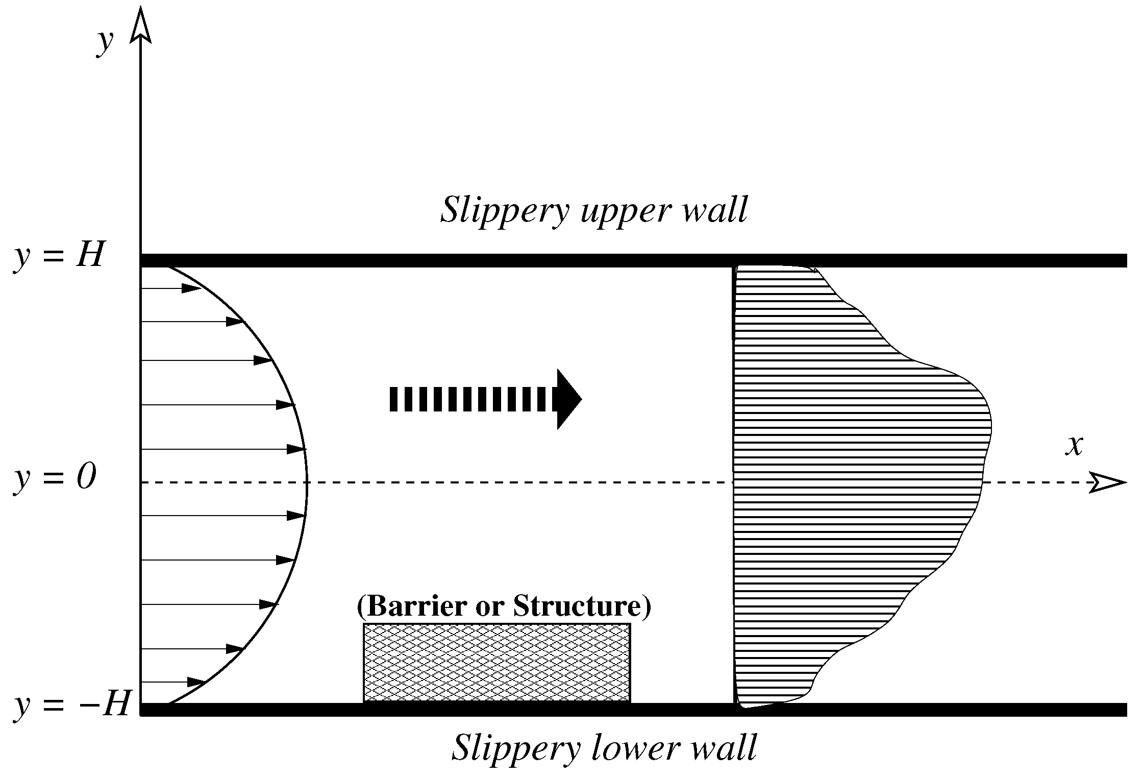
The linear stability of a pressure-driven laminar two-dimensional asymmetric flow of a Newtonian, incompressible fluid in a horizontal channel with wall velocity slip is considered. The fluid has density and viscosity . Initially the flow might be symmetric with respect to the centerline of the channel, but later it becomes asymmetric. As shown in Figure 1, this can be possible because of the presence of some barrier/structures at a certain special position near the wall boundary inside the flow system or because of some cross-flow. The channel is long enough to neglect the initial and end effects. A Cartesian coordinate system is appointed for the flow system by taking the x- and y-axis along and perpendicular to the centerline of the channel . The walls of the channel are located at and are slippery or hydrophobic in nature.
The dimensional governing equations are the continuity and the Navier–Stokes equations, read as
The boundary conditions are the velocity slip condition at the channel walls. It is to be noted that the walls may not be the composition of the same materials. We suppose that the physical/chemical properties and characteristics of the upper and lower wall are not similar. As a result, the slip effect of the upper and lower wall on the flow system is different (called non-symmetric slip [31]). Such differences in the wall slip can arise when the surface chemistry, surface wettability and surface roughness at the walls of the channel are distinct [26]. Following the formulation of Lauga and Cossu [31], the slip boundary conditions at the upper and lower wall (, 2, respectively) are taken as follows (dimensional):
In the equations, is the velocity vector, and p and t denote the pressure and time. and are the dimensional slip parameter (namely, the slip length) for the upper and lower wall, respectively. Both the walls have the same amount of slip if (symmetric slip).
The equations and the boundary conditions are made non-dimensional by using the following scales:
In the above, H is the length scale and V is the velocity scale, which corresponds to the average velocity across the channel. Using the dimensionless flow variables, the dimensionless equations and boundary conditions are the following (after suppressing asterisks ()):
At the slippery upper and lower walls (), we have
The parameter, is the Reynolds number, and are the dimensionless slip parameter for the upper and lower wall, respectively.
2.2. Mean Velocity Profile
The set of governing equations defined in the above section describe a parallel/nearly parallel channel flow. Asymmetric micro-channel flow belongs to the class of nearly parallel flow. It is well known that for the stability analysis of a perturbed flow, one needs to have a mean or basic initial flow profile. To obtain an approximated mean asymmetric underlying flow, we make the following two assumptions: (a) the basic flow pattern is time-invariant or very weakly time-dependent at the position in which the stability analysis is performed, and (b) the mean flow profile has significant asymmetry about the centerline. The mean velocity field of the fully developed flow at that particular position can be approximated by , which satisfies the condition at the walls (). Hereat, following the formulation of Fransson and Alfredsson [8], Kachuma and Sobey [9] and Fu and Joseph [11], we have considered a typical mean velocity profile, which takes into account the effects of asymmetry together with wall slip and is given by
where , , , and and are two model parameters that are used to capture asymmetry of the mean flow system; controls the skewness/curvature of the velocity profile, and the maximum velocity is operated by . It is known that changes in skewness and maximum velocity of a mean flow field affect the shear rate, which in turn gives influence to the hydrodynamic stability of the system. Considering the numerical solution of the Navier–Stokes equation and the least squares fit of flow parameters, Kachuma and Sobey [9] showed the existence of a flow region after the barrier/step where the above model’s basic flow (Equation (9) with ) fits well to true longitudinal velocity. Our approximated mean flow solution is similar to the polynomial-type solution suggested by Fu and Joseph [11] for asymmetric flow in channels. When , the limiting flow is plane Poiseuille in a slipper channel [31], and in addition, if , then it is plane Poiseuille in a rigid channel (with ). The multiplicative factor K in the mean flow is obtained by fixing the flux as
The mean profile is asymmetric with respect to the centerline, but still it is parallel-type. The velocity profile defined in Equation (9) can only be found at a location away from the initial flow position (see Figure 1). This implies that the analysis takes place at a point of the channel at which the flow is no longer symmetric, and so the analysis that follows is based on one kind of “frozen time” approximation [35]. Further, the slip parameters and are of small magnitude but can give significant influence to the mean flow in two possible ways: (i) changing the maximum velocity, and/or (ii) increasing/decreasing the asymmetry of the velocity profile near the walls as well as away from the walls.
The behavior of the mean velocity profile for different combinations of flow parameters is presented in Figure 2. Figure 2a presents the dependence of mean velocity profiles on and for the flow in a rigid channel (). The solid line with gives the well-known parabolic velocity profile for the plane Poiseuille flow. Figure 2a clearly indicates that a non-zero value of changes the maximum velocity and a non-zero affects the skewness of the velocity profile. Effects of symmetric () and asymmetric ( or ) wall slips are shown in Figure 2b–d. Both types of slip decrease the maximum velocity of the mean profile and increase the wall shear near the wall by increasing the wall velocity when the system has no back-flow (Figure 2b,d). In the case of back-flow, wall slip decreases the base/mean velocity near the wall where back-flow arrives (Figure 2c). It is important to note that, for certain choices of the parameter values (), the flow develops reverse-/back-flow near the channel wall (Figure 2a,c).
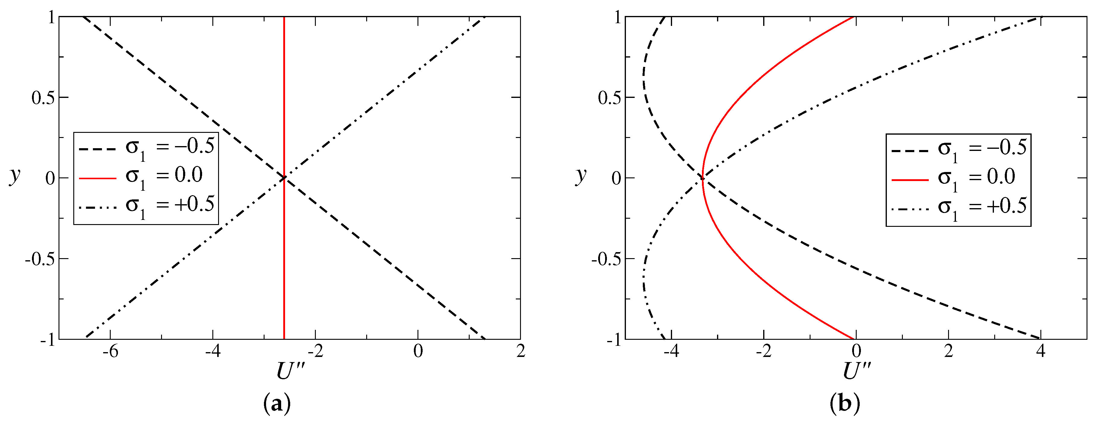
The characteristics of (the second derivative of velocity) are plotted in Figure 3 to check the inviscid instability of the flow using Rayleigh criteria [2]. As per Rayleigh’s theorem, if a wall-bounded flow is inviscidly unstable, then the mean velocity profile () must have an inflectional point inside its domain, that is, . Figure 3a,b is drawn for and , respectively. An inspection of Figure 3 reveals that the flow profile becomes inflectional for , which is in contrast to the symmetric flow considered by Lauga and Cossu [31]. The symmetric base flow used by Lauga and Cossu [31] is always inviscidly stable, but the asymmetric mean flow used in this study can be inviscidly unstable if . However, is always negative for both and when , indicating that the flow is inviscidly stable in this case.
2.3. Linear Stability Analysis
We wish to know how the linear stability limit varies for the channel flow with changes in the mean/basic velocity profile (U). The temporal evolution of the asymmetric mean flow in the presence of viscosity is investigated using a classic modal stability technique. Considering the normal mode analysis for the mean underlying flow, all the flow variables are split into the base/mean state quantities and two-dimensional perturbations. The infinitesimal perturbations are taken as
where is the wave number in the streamwise direction, () is the frequency of the two-dimensional disturbance, and c is the complex wave speed (). The flow is temporally stable if , unstable if , and neutrally stable if . Expressing the velocity perturbations in terms of the stream function perturbation as (), the classical Orr–Sommerfeld equation is derived using the standard procedure [1] and is given by the following (after suppressing hat symbols):
The boundary conditions in terms of stream function are
In the above equations, prime denotes differentiation with respect to y.
The Orr–Sommerfeld system is numerically solved using the Chebyshev spectral collocation method [46] with the help of the software MATLAB (R2017a, MathWorks, Inc., Natick, MA, USA). A sufficient number of grid points (Chebyshev collocation points) are taken to obtain an accuracy of at least five decimal places in the range of parameters considered.
3. Results and Discussion
The stability results are first obtained for the plane Poiseuille flow in a rigid/slippery channel to check the correctness of our numerical code by validating the available results in literature. We found that the critical Reynolds number () for the rigid channel case is , and it is of the critical Reynolds number () obtained by Drazin and Reid [1] in their study. We remark that, in the present study, the Reynolds number is based on the average velocity; however, for Drazin and Reid, the Reynolds number was defined as based on the maximum velocity. In view of the choice of characteristic velocity scale as the maximum velocity by Lauga and Cossu [31], in this study is times that obtained by Lauga and Cossu [31], for all . The results obtained from our code agree with the available results for both and after considering the proper scaling.
Figure 4 presents the growth rate for the most unstable mode of the perturbed flow for different values of and when the Reynolds number . The solid lines (for ) render the results for the plane Poiseuille flow with [31] and without [1] wall slip. Figure 4a discovers the results of rigid channel flow () considered by Kachuma and Sobey [9]. It is evident from Figure 4b that symmetric-type wall slip has the motivation to suppress the unstable mode by decreasing the growth and the range of unstable wave numbers, except in the case . In the presence of model parameters (non-zero and/or ), the growth rate is higher for the set of unstable wave numbers. The growth rate is dominant for because of the occurrence of sharp skewness in the velocity profile (see Figure 2).
The effects of symmetric and non-symmetric slip on the growth rate of the asymmetric flow are investigated more neatly in Figure 5. The mean velocity profile contains only one non-zero model parameter () in Figure 5a–d, the values of the model parameters are and . In the absence of the skewness parameter (), both types of slip stabilize the flow by reducing the growth rate of the disturbances with respect to time for all wave numbers. However, in the presence of back-flow (for ; see Figure 2) near the wall, velocity slip promotes the growth of disturbance as compared to the no-slip case for the considered value of the Reynolds number (; Figure 5c,d). Figure 5d shows that the growth rate is maximum when the system has velocity slip only on the upper wall ().
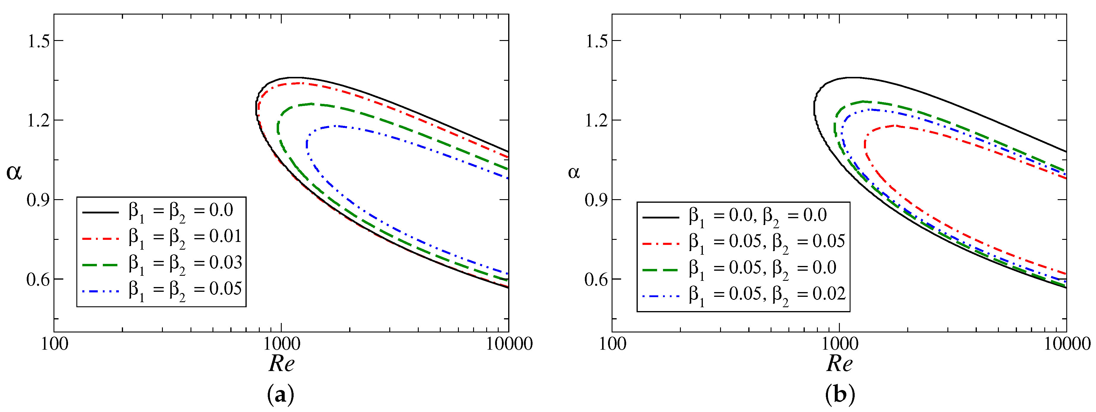
Neutral stability boundaries for different wall slips are presented in Figure 6. The values of the modeled parameters used in this figure are and , which suggests a change in maximum velocity alone. Curves with correspond to the rigid-channel case results. Figure 6 clearly points out that the asymmetric flow with is very much unstable as compared to the classical symmetric slippery channel flow studied by Lauga and Cossu [31]. The asymmetric flow is unstable at Reynolds numbers () smaller than 1000, and thus the critical Reynolds number () for this flow is much less than that for the case of the plane Poiseuille flow (). This may create a serious issue for the applications in which one requires a more stable asymmetric flow. The results for a slippery channel confirm that such a difficulty could be overcome by designing the wall as a slippery or hydrophobic surface. The flow is more stable because of the presence of velocity slip at the walls for the considered flow parameter in Figure 6. Wall slip significantly delays the occurrence of the instability by means of increasing the critical Reynolds number and lowering the bandwidth of unstable wave numbers. We note that the flow with velocity slip only at the upper wall () is more unstable (Figure 6b) as compared to the flow with velocity slip only at the lower wall ().
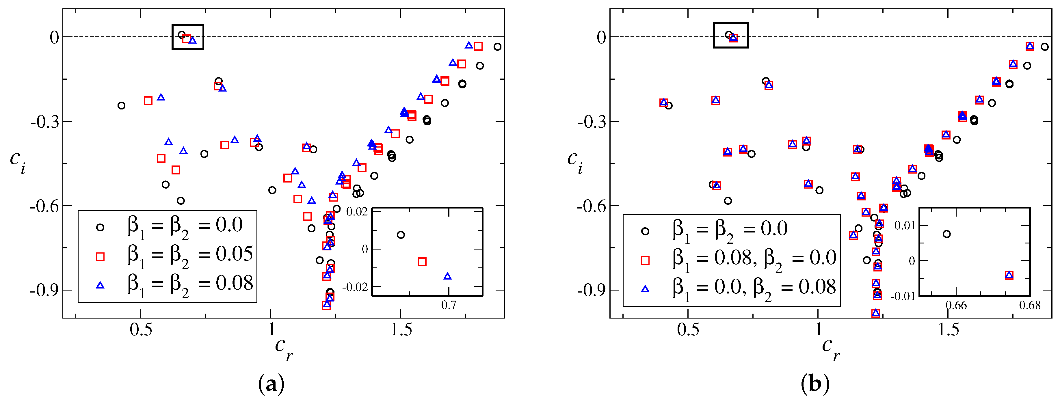
The spectrum of the Orr–Sommerfeld operator for the above flow configuration is framed in Figure 7, when the Reynolds number . The well-known Y shape for the channel flow is formed by the eigenvalues in the complex plane. The classical A, P and S branches [2] are present with the unstable mode on the branch A. The behaviour of the most unstable eigenmodes for different slip parameters are shown by the inset plot. Both symmetric- and asymmetric-type slips suppress the growth rate of the most unstable mode, but the effect of symmetric slip (Figure 7a) is stronger. Moreover, all the eigenmodes are stable for slippery channel flow. In the case of asymmetric slip, the nature of the most excited mode is shown in Figure 7b for two different configurations of wall slip.
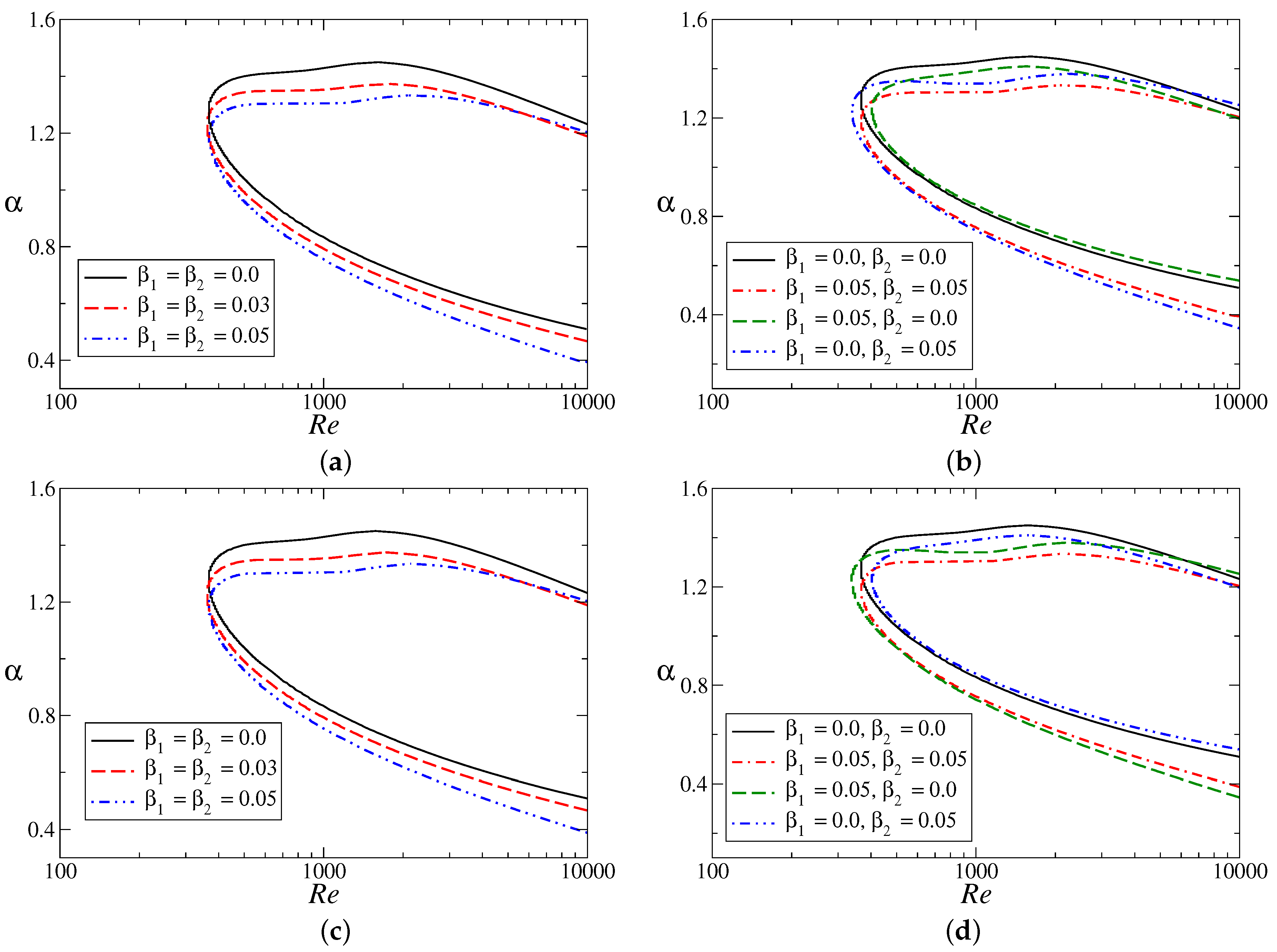
Next, we move to the flow configuration for which both the model parameters are non-zero. Figure 8 displays stability boundaries in the floor. The asymmetric channel flow is unstable at very low Reynolds numbers (critical Reynolds number is of ) for the parameter values and (Figure 8a,b), and (Figure 8c,d). There is no qualitative change in the stability curves as a result of the sign change of (skewness changing parameter). Additionally, symmetric slip has a minor effect in this parameter range. However, asymmetric-type slip plays a very interesting role depending on the value of (Figure 8b,d). Asymmetric-type wall velocity slip can destabilize the flow by decreasing the critical Reynolds number (see Figure 8b with and Figure 8d with ). Most importantly, the presence of slip only on the upper wall stabilizes the flow system when (>0; Figure 8b) and it destabilizes the flow when (<0; Figure 8d). The reverse statement is true for the flow configuration with velocity slip only on the lower wall. We note that the symmetry and skewness of the velocity profile are completely dependent on the absolute value as well as on the sign of the parameter .
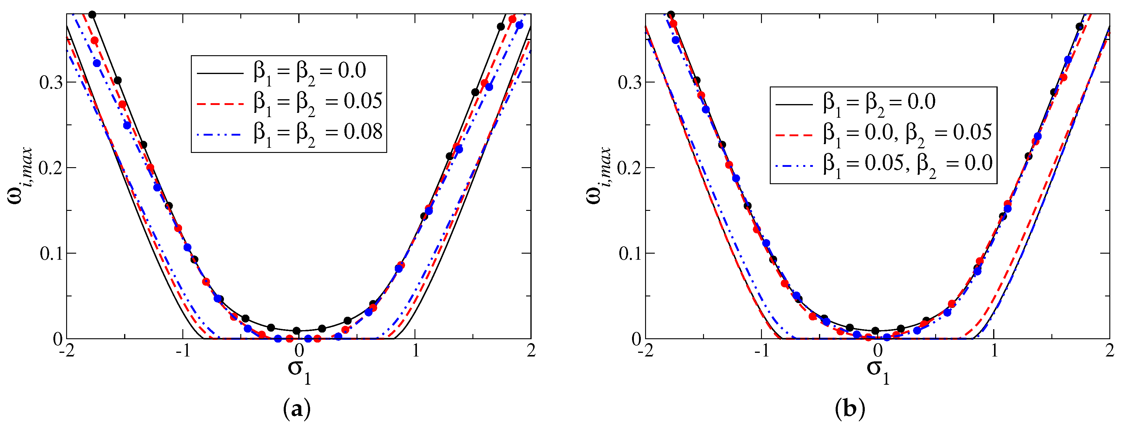
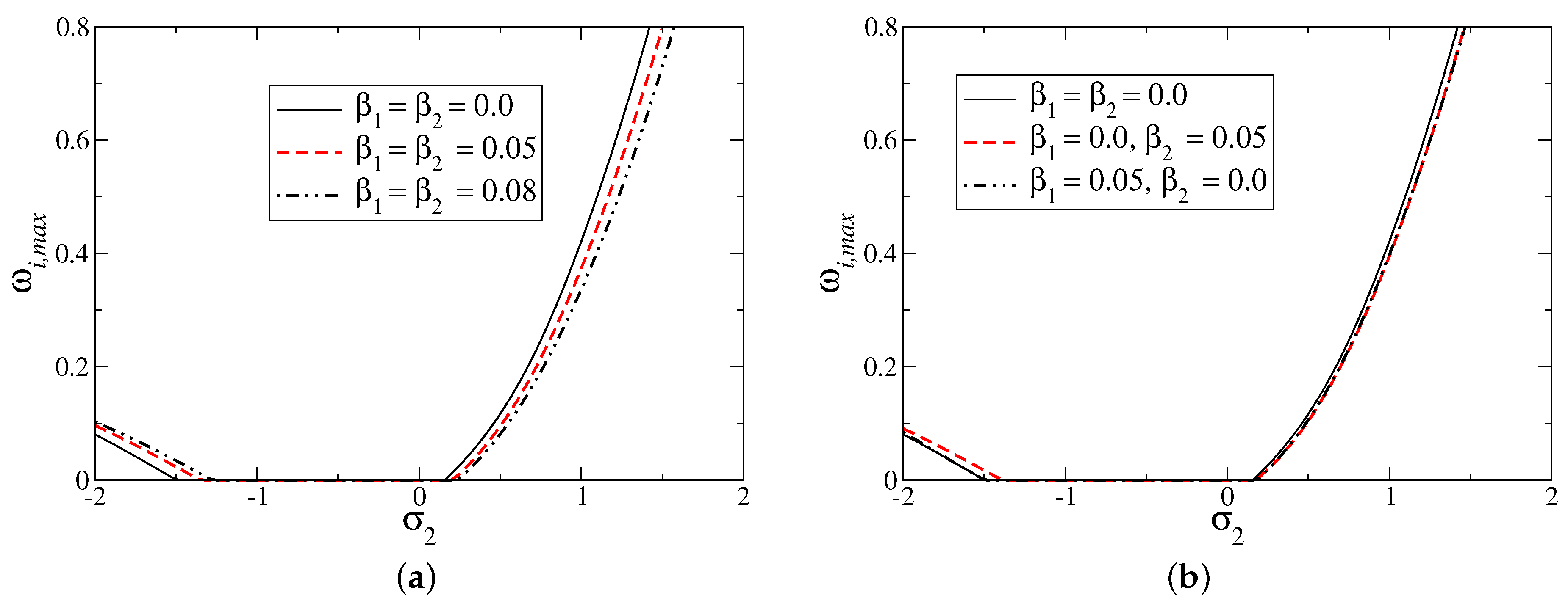
Figure 9 and Figure 10 are drawn to check the effects of (when is fixed) and (when is fixed) on the maximum growth () over all the unstable wave numbers for a fixed Raynolds number (). The flow system is unstable () for if and for if (see Figure 9). Wall slip has dual influences on the maximum growth rate depending on the value of . It can stabilize the flow by reducing the time growth of the dominant disturbance for a moderate to high magnitude of , but a destabilizing role of wall slip is found for a smaller magnitude of (Figure 9a). The twofold behaviour of the asymmetric slip is shown in Figure 9b. Figure 10 shows that the instability of the flow depends monotonically on the positive in the case of fixed . For positive values of , wall velocity slip suppresses the most unstable mode because of a reduction in the maximum growth rate, which is in contrast with .
We have summarized instability fashion at a fixed Reynolds number () by drawing contours of maximum growth rate (), considering all modes and across a range of , for no-slip (Figure 11a) and symmetric slip (Figure 11b) conditions. This regime diagram in plane gives the overall instability ceremonial. Note that in the unstable region, . Figure 11 exposes that both the flow parameters and play a major role to determine the stability at a given and . A region defined by and is most stable, and flow is destabilized outside this region. Overall, the configuration with higher magnitude of , is more unstable. By a close inspection, we see that the flow instability is regulated by the symmetric slip but that stabilization or destabilization completely depends on the typical combination of and values.
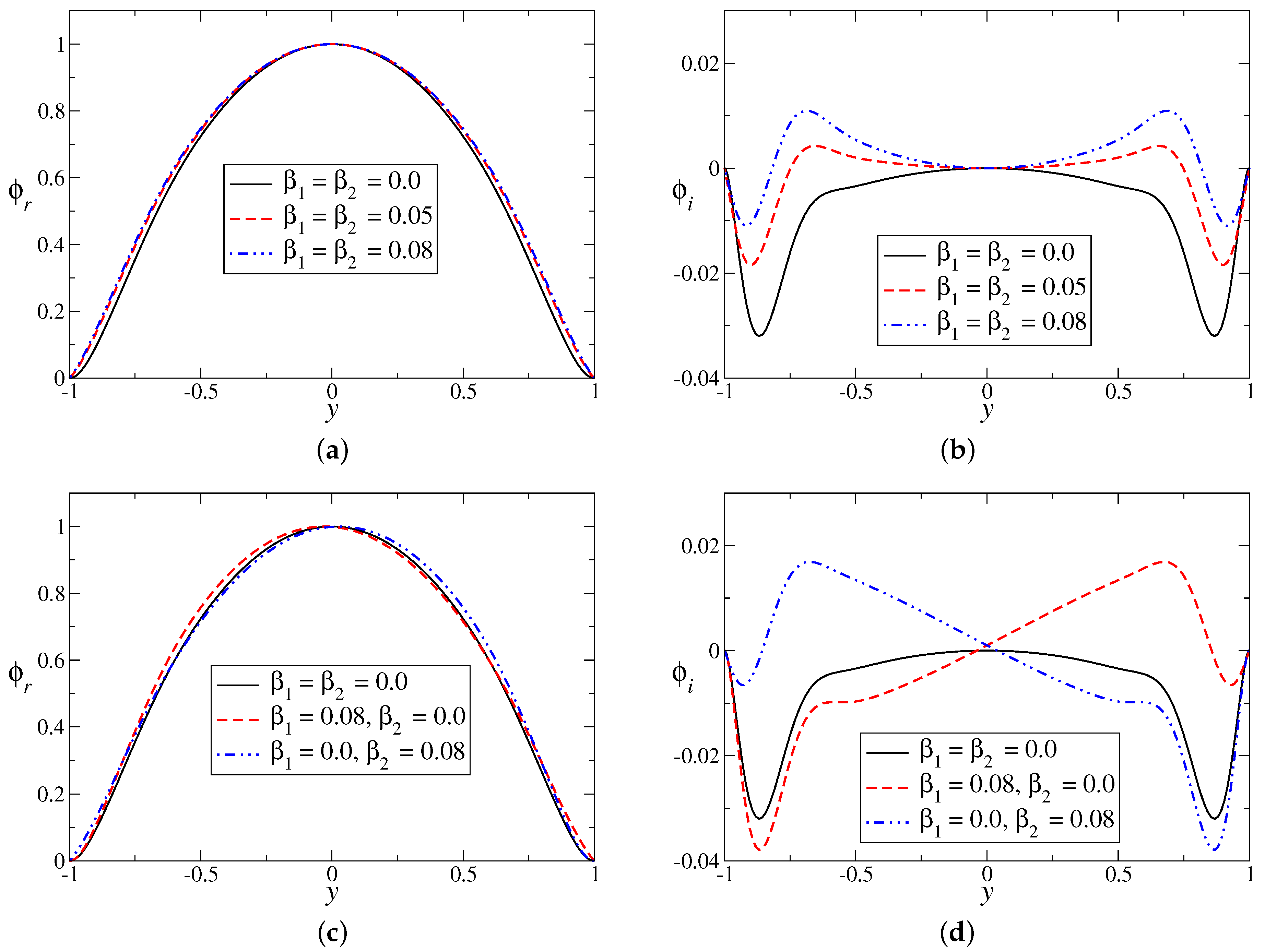
The sample set of eigenfunctions for the most unstable eigenmode are shown in Figure 12. It is notable that the presence of wall velocity slip has disturbed the look of the typical eigenfunctions. The real () and imaginary () part of stream functions are presented in Figure 12a,c and in Figure 12b,d, respectively, for symmetric and asymmetric slip conditions. Although is weakly dependent on slip parameters, the wall velocity slips destroy the symmetry of for the case of asymmetric slip (Figure 12d). This may provide some mechanism in terms of energy disturbance between the mean and perturbed flow, for the dynamics of the flow instabilities.
4. Conclusions
A thorough modal linear stability analysis of the asymmetric channel flow has been conducted in the presence of wall velocity slip. The walls of the channel were coated/made either with the same material or different materials, and the cases were handled by imposing symmetric and non-symmetric Navier slip conditions, respectively. Skewness and maximum velocity of the underlying asymmetric flow were regulated by two modeled parameters ( and ) together with slip parameters ( and ). We note that controls the skewness/curvature of the velocity profile, and the maximum velocity is operated by . The main motivation is to understand under which parameter range and conditions the stabilizing or destabilizing effects are maximum. The stability characteristics of the asymmetric flow are strikingly different as compared to the corresponding symmetric flow in a slippery channel.
The results confirm that moderate asymmetry has very significant effects on the stability of Poiseuille-type parallel/nearly parallel flows. The asymmetric slippery channel flow is unstable for a Reynolds number of , which is in contrast to the case of symmetric slippery channel flow [31], as in this case, the critical Reynolds number is higher than a few thousand. This is due to the change in the skewness and maximum velocity of the mean flow. Such a change inside the flow may transfer more energy from the mean flow to the perturbed flow to make the perturbed flow more unstable. Wall velocity slip has both stabilizing as well as destabilizing effects on the stability of the asymmetric flow by increasing/decreasing the critical Reynolds number and the set of unstable wave numbers. The behaviour of the mean velocity is explicitly dependent on the slip parameters, and thus wall slip controls the shear rate of the flow near the walls as well as away from the walls. Both symmetric and asymmetric types of slip stabilize the flow as compared to the no-slip configuration, for which the skewness parameter is absent (; Figure 5a,b and Figure 6). A destabilizing influence of wall slip is found in the presence of both non-zero and (Figure 5c,d and Figure 8). The results obtained in this study also indicate that a dual role (stabilizing or destabilizing) of wall slip relies on the existence of the velocity slip at the upper or lower wall of the channel and on the modeled parameters (, ) of the mean velocity.
Ultimately, the essence of the current investigation’s results is that asymmetry and wall velocity slip both significantly affect the stability of the flow in confined geometries. The instability of asymmetric Poiseuille-type flow can be ruled by designing the boundary walls as a hydrophobic/slippery/coated surface or porous surface with small permeability. In these surfaces, the Navier slip condition with appropriate slip length (alternatively Knudsen number) is a very good approximation for wall velocity. The engineering of such surfaces is of great interest in a large number of real-life applications and in a range of technologies, from lubrication to microfluidics. In future, the author aims to conduct hydrodynamic stability analysis of channel flow with “beyond-slip” models [38].
Acknowledgments
The author sincerely thanks to the reviewers for their valuable comments and suggestions which have helped in improving the quality of the paper. There is no source of funding for this research work.
Conflicts of Interest
The author declares no conflict of interest.
References
- Drazin, P.G.; Reid, W.H. Hydrodynamic Stability; Cambridge University Press: Cambridge, UK, 1985. [Google Scholar]
- Schmid, P.J.; Henningson, D.S. Stability and Transition in Shear Flows; Springer: New York, NY, USA, 2001. [Google Scholar]
- Muthu, P.; Berhane, T. Fluid flow in an asymmetric channel. Tamkang J. Math. 2011, 42, 149–162. [Google Scholar] [CrossRef]
- Neto, C.; Evans, D.R.; Bonaccurso, E.; Butt, H.-J.; Craig, V.S.J. Boundary slip in Newtonian liquids: A review of experimental studies. Rep. Prog. Phys. 2005, 68, 2859–2897. [Google Scholar] [CrossRef]
- Meksyn, D. Stability of Viscous Flow Over Concave Cylindrical Surfaces. Proc. R. Soc. Lond. A 1950, 203, 253–265. [Google Scholar] [CrossRef]
- Mack, L.M. A numerical study of the temporal eigenvalue spectrum of the Blasius boundary layer. J. Fluid Mech. 1976, 73, 497–520. [Google Scholar] [CrossRef]
- Bertolotti, F.P.; Herbert, T.; Spalart, P.R. Linear and nonlinear stability of the Blasius boundary layer. J. Fluid Mech. 1992, 242, 441–474. [Google Scholar] [CrossRef]
- Fransson, J.H.M.; Alfredsson, P.H. On the hydrodynamic stability of channel flow with cross flow. Phys. Fluids 2003, 15, 436–441. [Google Scholar] [CrossRef]
- Kachuma, D.; Sobey, I.J. Linear Instability of Asymmetric Poiseuille Flows; Report No. 07/21; Oxford University Computing Laboratory: Oxford, UK, 2007. [Google Scholar]
- Webber, M. Instability of Fluid Flows, Including Boundary Slip. Ph.D. Thesis, Durham University, Durham, UK, 2007. Available online: http://etheses.dur.ac.uk/2308/ (accessed on 1 March 2017).
- Fu, T.S.; Joseph, D.D. Linear Instability of Asymmetric Flow in Channels. Phys. Fluids 1970, 13, 217–221. [Google Scholar] [CrossRef]
- Sobey, I.J. Observation of waves during oscillatory channel flow. J. Fluid Mech. 1985, 151, 395–426. [Google Scholar] [CrossRef]
- Bottaro, A.; Corbett, P.; Luchini, P. The effect of base flow variation on flow stability. J. Fluid Mech. 2003, 476, 293–302. [Google Scholar] [CrossRef]
- Marquet, O.; Sipp, D.; Jacquin, L. Sensitivity analysis and passive control of cylinder flow. J. Fluid Mech. 2008, 615, 221–252. [Google Scholar] [CrossRef]
- Brandt, L.; Sipp, D.; Pralits, J.O.; Marquet, O. Effect of base-flow variation in noise amplifiers: The flat-plate boundary layer. J. Fluid Mech. 2011, 678, 503–528. [Google Scholar] [CrossRef]
- Sochi, T. Slip at Fluid-Solid Interface. Polym. Rev. 2011, 51, 309–340. [Google Scholar] [CrossRef]
- Zhu, Y.X.; Granick, S. Limits of hydrodynamic no-slip boundary condition. Phys. Rev. Lett. 2002, 88, 106102. [Google Scholar] [CrossRef] [PubMed]
- Lauga, E.; Brenner, M.P.; Stone, H.A. Hand Book of Experimental Fluid Dynamics; Foss, J.F., Tropea, C., Yarin, A., Eds.; Springer: New York, NY, USA, 2005. [Google Scholar]
- Beavers, G.S.; Joseph, D.D. Boundary conditions at a naturally permeable wall. J. Fluid Mech. 1967, 30, 197–207. [Google Scholar] [CrossRef]
- Watanabe, Y.K.; Mizunuma, H. Slip of Newtonian fluids at solid boundary. JSME. Int. J. Ser. B 1998, 41, 525–529. [Google Scholar] [CrossRef]
- Choi, C.H.; Westin, K.J.A.; Breur, K.S. Apparent slip flows in hydrophilic and hydrophobic microchannels. Phys. Fluids 2003, 15, 2897–2902. [Google Scholar] [CrossRef]
- Rund, A.; Scholle, M.; Aksel, N. Drag reduction and improvement of material transport in creeping films. Arch. Appl. Mech. 2006, 75, 93–112. [Google Scholar]
- Min, T.; Kim, J. Effects of hydrophobic surface on stability and transition. Phys. Fluids 2005, 17, 108106. [Google Scholar] [CrossRef]
- You, X.Y.; Zheng, J.R. Stability of liquid-liquid stratified microchannel flow under the effects of boundary slip. Int. J. Chem. React. Eng. 2009, 7, A85. [Google Scholar] [CrossRef]
- Miksis, M.J.; Davis, S.H. Slip over rough and coated surfaces. J. Fluid Mech. 1994, 273, 125–139. [Google Scholar] [CrossRef]
- Zhu, Y.; Granick, S. Rate-dependent slip of Newtonian liquid at smooth surfaces. Phys. Rev. Lett. 2001, 87, 096105. [Google Scholar] [CrossRef] [PubMed]
- Bonaccurso, E.; Kappl, M.; Butt, H.J. Hydrodynamic force measurements: Boundary slip of hydrophobic surfaces and electrokinetic effects. Phys. Rev. Lett. 2002, 88, 076103. [Google Scholar] [CrossRef] [PubMed]
- Vinogradova, O.I. Slippage of water over hydrophobic surfaces. Int. J. Miner. Process. 1999, 56, 31–60. [Google Scholar] [CrossRef]
- Gersting, J.M. Hydrodynamic stability of plane porous slip flow. Phys. Fluids 1974, 17, 2126–2127. [Google Scholar] [CrossRef]
- Pralits, J.O.; Alinovi, E.; Bottaro, A. Stability of the flow in a plane microchannel with one or two super hydrophobic walls. Phys. Rev. Fluids 2017, 2, 013901. [Google Scholar] [CrossRef]
- Lauga, E.; Cossu, C. A note on the stability of slip channel flows. Phys. Fluids 2005, 17, 088106. [Google Scholar] [CrossRef] [Green Version]
- Gan, C.J.; Wu, Z.N. Short-wave instability due to wall slip and numerical observation of wall-slip instability for microchannel flows. J. Fluid Mech. 2006, 550, 289–306. [Google Scholar] [CrossRef]
- Ren, L.; Chen, J.-G.; Zhu, K.-Q. Dual role of wall slip on linear stability of plane Poiseuille flow. Chin. Phys. Lett. 2008, 25, 601–603. [Google Scholar]
- Sahu, K.C.; Sameen, A.; Govindarajan, R. The relative roles of divergence and velocity slip in the stability of plane channel flow. Eur. Phys. J. Appl. Phys. 2008, 44, 101–107. [Google Scholar] [CrossRef]
- Ghosh, S.; Usha, R.; Sahu, K.C. Linear stability anlysis of miscible two-fluid flow in a channel with velocity slip at the walls. Phys. Fluids 2014, 26, 014107. [Google Scholar] [CrossRef] [Green Version]
- Samanta, A.; Quil, C.R.; Goyeau, B. A falling film down a slippery inclined plane. J. Fluid Mech. 2011, 684, 353–383. [Google Scholar] [CrossRef]
- Pascal, J.P. Linear stability of fluid flow down a porous inclined plane. J. Phys. D Appl. Phys. 1999, 32, 417–422. [Google Scholar] [CrossRef]
- Torrilhon, M. Modeling non equilibrium gas flow based on moment equations. Annu. Rev. Fluid Mech. 2016, 48, 429–458. [Google Scholar] [CrossRef]
- Kaiktsis, L.; Monkewitz, P.A. Global destabilization of flow over a backward-facing step. Phys. Fluids 2003, 42, 3647–3658. [Google Scholar] [CrossRef]
- Adachi, T.; Uehara, H. Linear stability analysis of flow in a periodically grooved channel. Int. J. Numer. Methods Fluids 2003, 41, 601–613. [Google Scholar] [CrossRef]
- Mohammadi, A.; Moradi, H.V.; Floryan, J.M. New instability mode in a grooved channel. J. Fluid Mech. 2015, 778, 691–720. [Google Scholar] [CrossRef]
- Sahoo, T.; Chan, A.T.; Chwang, A.T. Scattering of oblique surface waves by permeable barriers. Ocean Eng. 2000, 126, 196–205. [Google Scholar] [CrossRef]
- Tsangaris, S.; Leiter, E. On laminar steady flow in sinusoidal channels. J. Eng. Math. 1984, 18, 89–103. [Google Scholar] [CrossRef]
- Debus, J.-D.; Mendoza, M.; Succi, S.; Herrmann, H.J. Poiseuille flow in curved spaces. Phys. Rev. E 2016, 93, 043316. [Google Scholar] [CrossRef] [PubMed]
- Bers, A.; Brenner, M.P.; Stone, H.A. Handbook of Plasma Physics; Rosenbluth, M.N., Sagdeev, R.Z., Eds.; Elsevier: Amsterdam, The Netherlands, 1983; Volume 1. [Google Scholar]
- Canuto, C.; Hussaini, M.Y.; Quarteroni, A.; Zang, T.A. Spectral Methods in Fluid Dynamics, 1st ed.; Springer: New York, NY, USA, 1987. [Google Scholar]
Figure 1.
Schematic of the considered flow system in two-dimensional geometry. The resultant flow is asymmetric with respect the centerline of the channel (y-axis). Slippery walls are at .
Figure 1.
Schematic of the considered flow system in two-dimensional geometry. The resultant flow is asymmetric with respect the centerline of the channel (y-axis). Slippery walls are at .

Figure 2.
Mean velocity profiles for: (a) , different and ; (b) , ; (c) , ; and (d) , . (b–d) contain slip cases results.
Figure 2.
Mean velocity profiles for: (a) , different and ; (b) , ; (c) , ; and (d) , . (b–d) contain slip cases results.
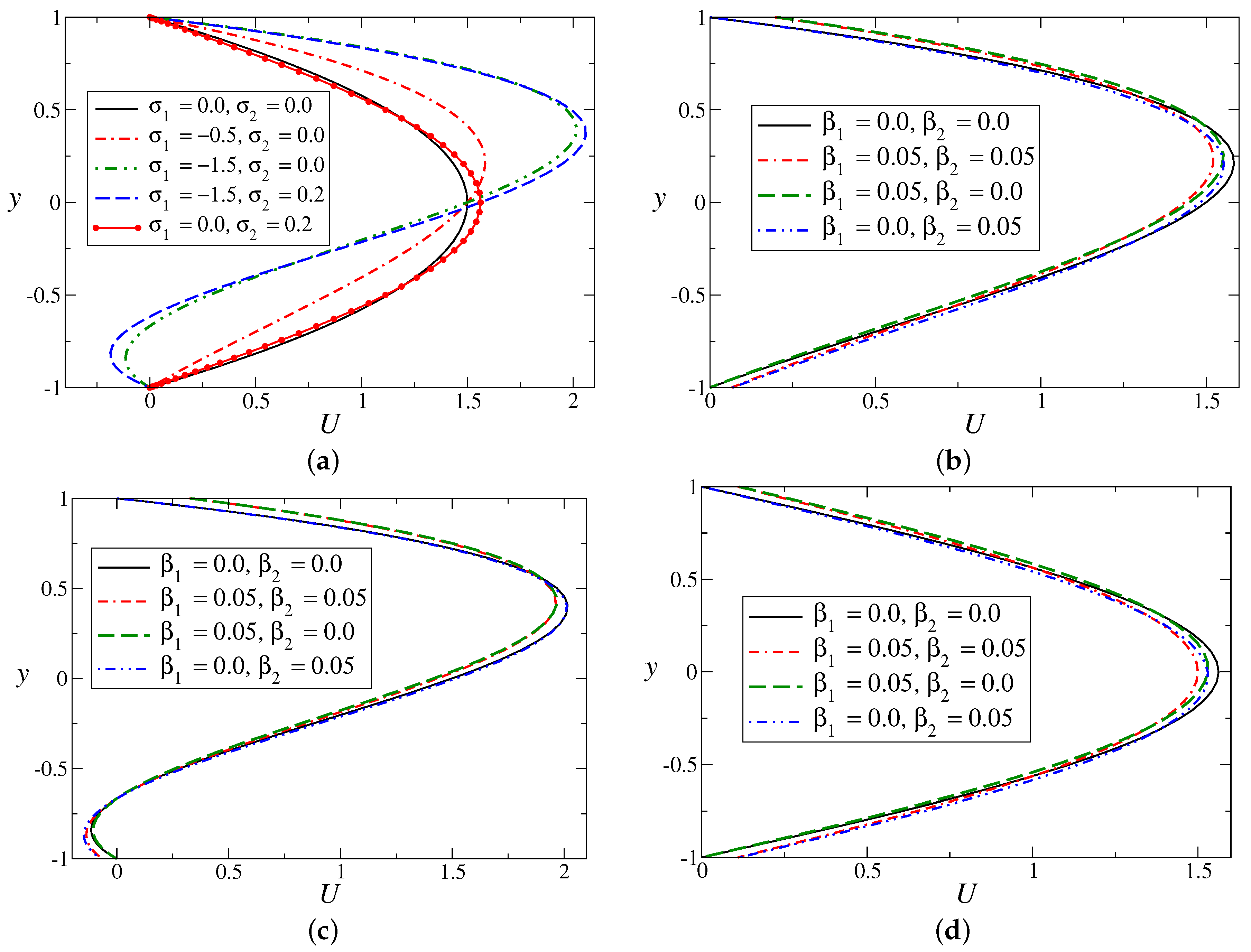
Figure 3.
Second derivative of mean velocity profiles (), for different values of : (a) ; (b) . In both the figures, symmetric slip () is considered.
Figure 3.
Second derivative of mean velocity profiles (), for different values of : (a) ; (b) . In both the figures, symmetric slip () is considered.

Figure 4.
Growth rate () curves for and different and : (a) (no slip); and (b) (symmetric slip).
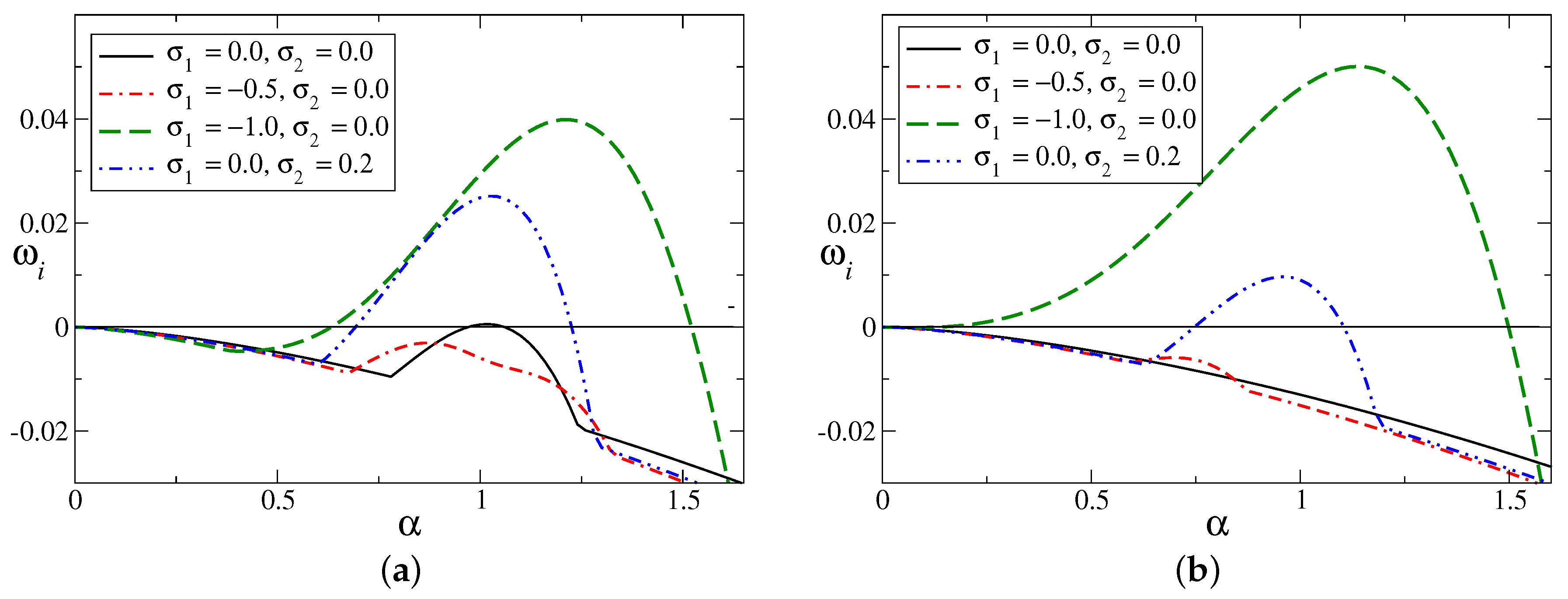
Figure 5.
Growth rate () curves for : (a,b) for , ; (c,d) for , . (a,c) Symmetric slip (), and (b,d) non-symmetric slip ().
Figure 5.
Growth rate () curves for : (a,b) for , ; (c,d) for , . (a,c) Symmetric slip (), and (b,d) non-symmetric slip ().
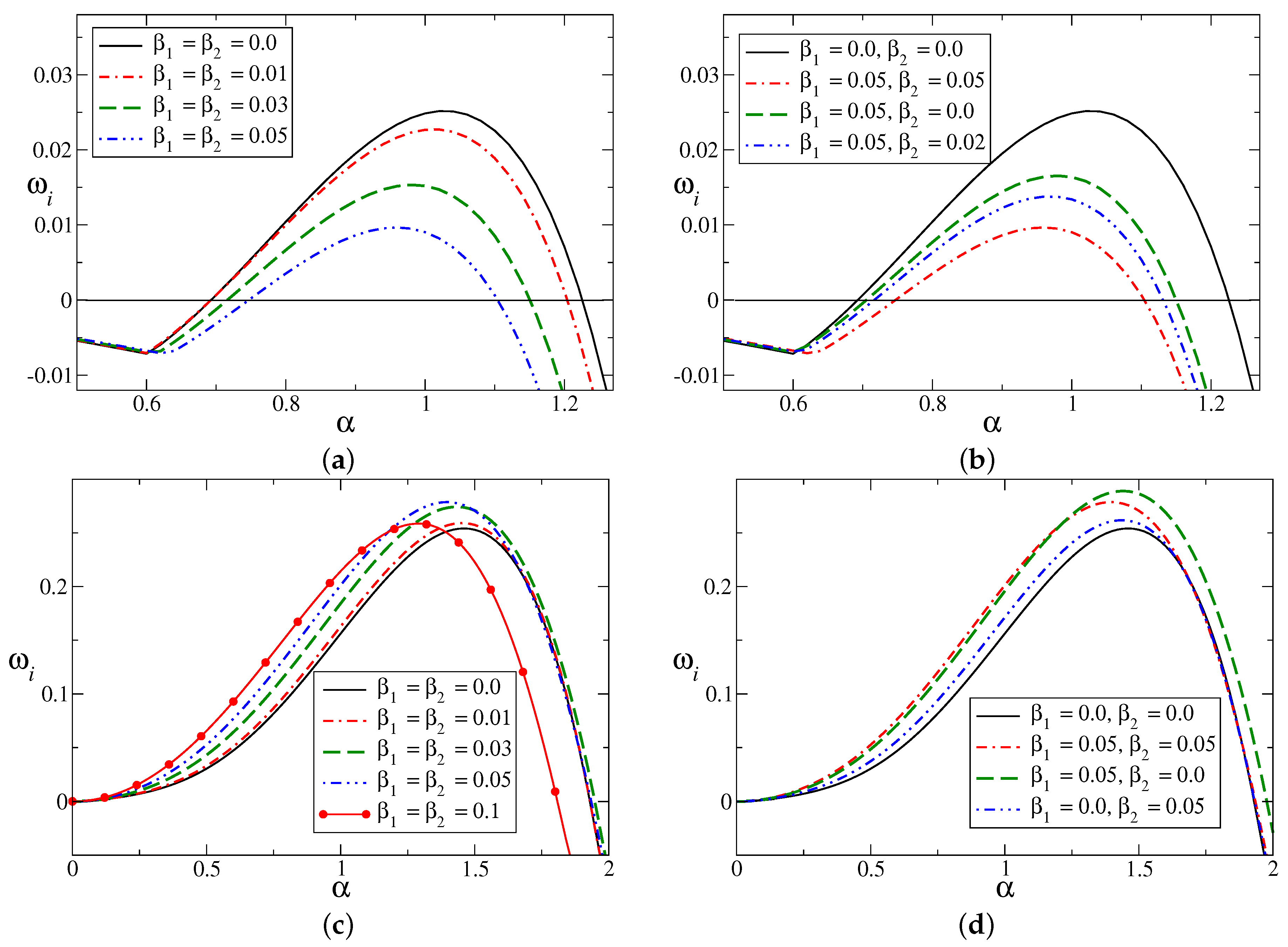
Figure 6.
Neutral stability boundaries for , : (a) symmetric slip (); and (b) non-symmetric slip ().
Figure 6.
Neutral stability boundaries for , : (a) symmetric slip (); and (b) non-symmetric slip ().

Figure 7.
Eigenspectra for , and : (a) with symmetric slip (); and (b) with non-symmetric slip ().

Figure 8.
Neutral stability curves: (a,b) , ; (c,d) , . (a,c) Symmetric slip; and (b,d) non-symmetric slip.
Figure 8.
Neutral stability curves: (a,b) , ; (c,d) , . (a,c) Symmetric slip; and (b,d) non-symmetric slip.

Figure 9.
Maximum growth rate () as a function of for and : (a) with symmetric slip (); and (b) with non-symmetric slip (). Curves with symbols are for .
Figure 9.
Maximum growth rate () as a function of for and : (a) with symmetric slip (); and (b) with non-symmetric slip (). Curves with symbols are for .

Figure 10.
Maximum growth rate () as a function of for : (a) symmetric slip () and (b) non-symmetric slip ().
Figure 10.
Maximum growth rate () as a function of for : (a) symmetric slip () and (b) non-symmetric slip ().

Figure 11.
Contours of maximum growth rate for : (a) symmetric slip (); and (b) non-symmetric slip ().
Figure 11.
Contours of maximum growth rate for : (a) symmetric slip (); and (b) non-symmetric slip ().
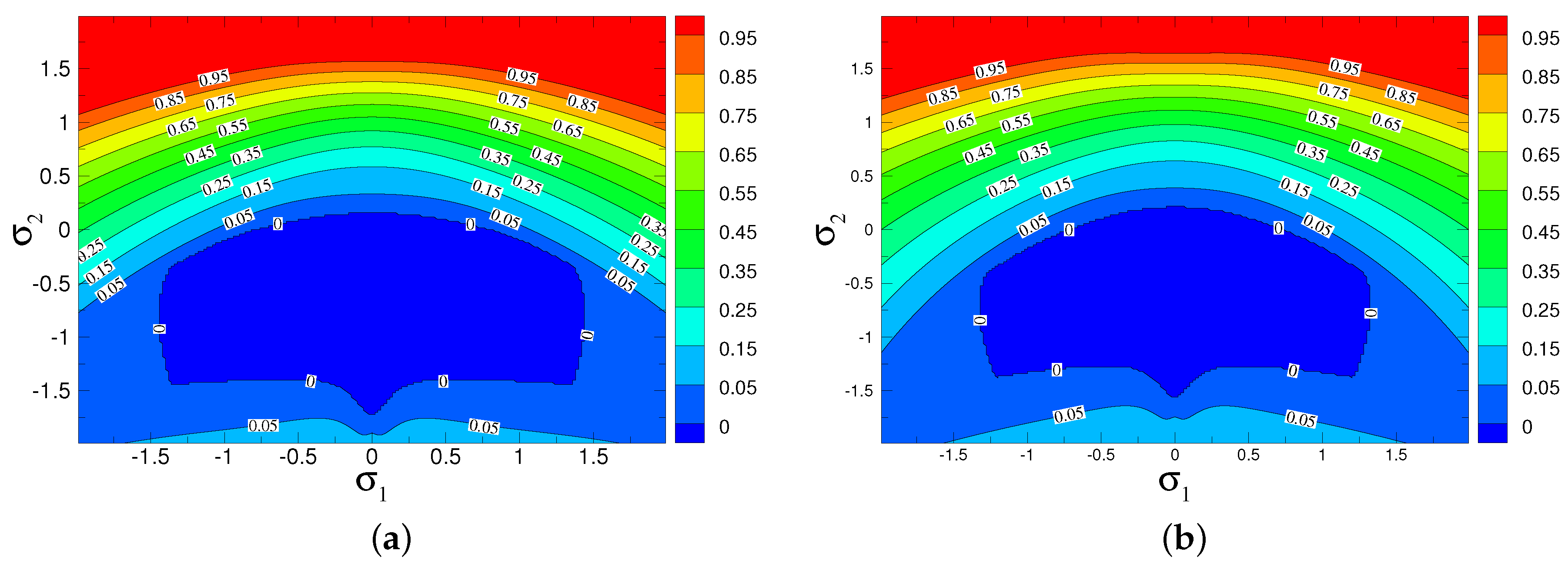
Figure 12.
Eigenfunctions for , and : (a,b) Symmetric slip (); and (c,d) non-symmetric slip (). The subscripts r and i represent the real and imaginary parts of the eigenfunction .
Figure 12.
Eigenfunctions for , and : (a,b) Symmetric slip (); and (c,d) non-symmetric slip (). The subscripts r and i represent the real and imaginary parts of the eigenfunction .
© 2017 by the author. Licensee MDPI, Basel, Switzerland. This article is an open access article distributed under the terms and conditions of the Creative Commons Attribution (CC BY) license (http://creativecommons.org/licenses/by/4.0/).
Share and Cite
MDPI and ACS Style
Ghosh, S. Relative Effects of Asymmetry and Wall Slip on the Stability of Plane Channel Flow. Fluids 2017, 2, 66. https://doi.org/10.3390/fluids2040066
AMA Style
Ghosh S. Relative Effects of Asymmetry and Wall Slip on the Stability of Plane Channel Flow. Fluids. 2017; 2(4):66. https://doi.org/10.3390/fluids2040066
Chicago/Turabian StyleGhosh, Sukhendu. 2017. "Relative Effects of Asymmetry and Wall Slip on the Stability of Plane Channel Flow" Fluids 2, no. 4: 66. https://doi.org/10.3390/fluids2040066