Fluid Dynamics and Mass Transfer in Spacer-Filled Membrane Channels: Effect of Uniform Channel-Gap Reduction Due to Fouling


1
Chemical Process and Energy Resources Institute, Centre for Research and Technology–Hellas, P.O. Box 60361, 6th km Charilaou-Thermi Road, Thermi, Thessaloniki GR570-01, Greece
2
Chemistry Department, Aristotle University of Thessaloniki, Thessaloniki 54124, Greece
*
Author to whom correspondence should be addressed.
Fluids 2018, 3(1), 12; https://doi.org/10.3390/fluids3010012
Submission received: 13 December 2017
/
Revised: 16 January 2018
/
Accepted: 26 January 2018
/
Published: 2 February 2018
(This article belongs to the Special Issue Flow and Heat or Mass Transfer in the Chemical Process Industry)
Abstract
:The time-varying flow field in spacer-filled channels of spiral-wound membrane (SWM) modules is mainly due to the development of fouling layers on the membranes that modify the channel geometry. The present study is part of an approach to tackling this extremely difficult dynamic problem at a small spatial scale, by uncoupling the fluid dynamics and mass transfer from the fouling-layer growth process. Therefore, fluid dynamics and mass transfer are studied for a spacer-filled channel whose geometry is altered by a uniform deposit thickness h. For this purpose, 3D direct numerical simulations are performed employing the “unit cell” approach with periodic boundary conditions. Specific thickness values are considered in the range 2.5–10% of the spacer-filament diameter D as well as other conditions of practical significance. The qualitative characteristics of the altered flow field are found to be very similar to those of the reference geometry with no gap reduction. For a given flow rate, the pressure drop, time-average wall-shear stresses and mass-transfer coefficients significantly increase with increasing thickness h due to reduced channel-gap, as expected. Correlations are obtained, applicable at the “unit cell” scale, of the friction factor f and Sherwood number Sh, which exhibit similar functional dependence of f and Sh on the Reynolds and Schmidt numbers as in the reference no-fouling case. In these correlations the effect of channel-gap reduction is incorporated, permitting predictions in the studied range of fouling-layer thickness (h/D) = 0–0.10. The usefulness of the new results and correlations is discussed in the context of ongoing research toward improved modeling and dynamic simulation of SWM-module operation.
1. Introduction
The spiral-wound membrane (SWM) module is the dominant element of the reverse osmosis (RO) and nanofiltration (NF) water-treatment plants, which are comprised of pressure vessels, each containing several SWM modules in series. Therefore, significant research and development (R&D) efforts have been invested aiming to optimize SWM-module design (for various applications) and improve its overall performance (e.g., [1,2]). The operation at steady state of a desalination SWM module, and of the entire RO plant, is characterized by an inherent spatial variability of all process parameters [3,4] due to the passage/filtration of purified water from the feed-side channels to the permeate side. However, in RO and NF plants there is also temporal variability due to fouling [5,6], usually caused by rejected organic and/or inorganic impurities depositing on the membrane surfaces, which leads to deterioration in plant performance; this undesirable variability (manifested in feed-pressure increase, for constant recovery, and in reduced salt rejection) is extremely difficult to predict, although it is necessary for developing optimal plant design and operation strategies. A direct attack of the full 3D dynamic problem, enabling simulation and prediction of the SWM and pressure-vessel performance from first principles, is impossible at present due to its complexity and considering the lack of understanding of some key physico-chemical interactions affecting fouling (e.g., [7,8,9]). Nevertheless, some efforts in that direction have been reported (e.g., [5,10]), in which significant simplifying assumptions have been made.
To address this complicated problem in a systematic manner, researchers have numerically analyzed, first, the flow field and mass transfer in restricted spatial domains of the spacer-filled membrane channels, as summarized in [11]. Significant work along these lines has been reported (focusing on small or intermediate spatial scales) aiming to understand the effect of spacer characteristics on flow and mass transfer (e.g., [12,13,14]) in order to optimize the feed-spacer geometry (e.g., [15,16,17]) and to study fouling, including bio-fouling (e.g., [18,19]) phenomena. These detailed studies of the flow field in the spacer-filled channels, focusing on a “unit cell” formed by the net-type spacers (also considering periodicity), have proven to be quite fruitful; in addition to improved basic understanding, they have yielded correlations of pressure drop and mass transfer applicable at “unit cell” scale [20,21]. Comprehensive modeling of flow and mass transfer throughout a membrane sheet (or a SWM module) can rely on such correlations in order to develop a reliable simulator of SWM performance at steady state [3,4,22,23] and to further a dynamic model and respective simulator accounting for a developing fouling layer [6,24]; the dynamic simulator, as a general-purpose tool, would enable reliable projections of the performance of a pressure vessel and of an entire desalination plant.
In practically all the aforementioned studies, a fairly idealized feed-side channel geometry is considered, with the membrane-channel gap characterized by the nominal thickness of the net-type spacer which is assumed to be in line- or point-contact with the bounding flat membranes. However, there are two main effects in practice that cause the real membrane channel gap to be smaller than the “reference gap”, with significant negative impact on the process; i.e., the pressure applied on the spacer-filled membrane envelopes during winding in SWM-module fabrication [1] and the foulants depositing on the membranes [8,25]. The former leads to the deformation of the membrane and/or the spacer, thereby effectively reducing the channel gap [1]; the latter effect manifests itself as deposit/fouling layers gradually developing on the active membrane surfaces. In general, the fouling layers considered here (in addition to the added resistance to permeation) tend to modify the detailed geometrical characteristics of the spacer-filled flow-channels, impacting on the transport phenomena therein. Therefore, this effect of channel-gap reduction merits particular attention for the improved understanding and comprehensive process modeling outlined above.
The scope of this work is to study in detail the effect of thickness h of a fouling layer (assumed to develop uniformly on the membranes) on hydrodynamics and mass transfer in the spacer-filled channels, under conditions representative of those prevailing in RO desalination plants. For this purpose, 3D-flow simulations were performed in “unit cells”, with geometry representative of typical commercial spacers, by employing advanced numerical techniques described in previous publications [20,21]. In the analysis and the reported results and correlations (for pressure drop and mass transfer), an additional parameter (h/D) is introduced, involving the fouling-layer thickness h made dimensionless with the diameter D of spacer filaments, the latter considered to be cylindrical.
2. Mathematical Formulation and Numerical Simulations
The base case of the problem at hand is the flow field within flat narrow channels (bounded by membranes) whose gap/height is determined by the nominal feed-spacer thickness. This geometry is commonly considered a satisfactory approximation of spacer-filled channels in spiral-wound elements, when no fouling or other channel deformation exists [20]. In the basic (or initial) geometry, shown in Figure 1a, a flat narrow channel is formed by the membrane-bounding surfaces, in contact with two layers of straight cylindrical filaments (comprising the spacer). The filaments of each layer are parallel and equidistant, while the two superposed layers have different orientation and “intersect” at a certain angle β. All cylindrical filaments have the same diameter (D), so that the channel gap or height (H) is twice the filament diameter (i.e., H = 2D). Another parameter of interest is the ratio (L/D) of distance L between the axes of symmetry of parallel filaments over the filament diameter D. It will be noted that recent studies (e.g., [26]) take into consideration the irregularities of the filament cylindrical shape, developing during filament extrusion and spacer fabrication. These irregularities, and their impact on the flow field, have to be taken into account in future studies, particularly in the context of fouling-layer development. The particular problem studied here involves fouling layers developing on both bounding membrane surfaces, but not on the spacer surfaces (Figure 1b). The thickness h of these fouling layers is considered to develop uniformly on both membrane surfaces, resulting in a flow channel with reduced gap, and reduced spacer-filament surfaces exposed to the flow, compared to the initial configuration, as indicated in Figure 1b.
As in previous similar studies [20,21] it is considered that the flow exhibits periodicity in each unit cell AXBY formed by four neighboring filaments (shown in Figure 1a); therefore, the detailed flow-field study is restricted to a computational domain indicated as ABCD in Figure 1a. The rationale and usefulness of adopting periodic boundary conditions to describe the flow field in the present case, as well as other types of transport phenomena in geometries with a periodic character, is discussed elsewhere [20,21].
Flow development and mass transport are governed by the Navier–Stokes, continuity and mass-transfer equations, considering that the fluid is Newtonian and incompressible:
The channel walls are assumed to be impermeable, which may be justified considering that the RO permeation velocities are much smaller than the feed-flow velocities. Consequently, no-slip and no penetration boundary conditions are considered on the channel walls and on the cylindrical filament surfaces. Additionally, for the mass-transfer simulations, uniform membrane wall/surface concentration, Cw, is assumed.
It is emphasized that the results of this study are obtained through a direct numerical simulation (DNS) involving Equation 1a–c, without the introduction of any approximation regarding flow development or turbulence modeling. A commercial CFD code (FLUENT, v.6.2.16, ANSYS, Canonsburg, PA, USA) is used, which employs the finite-volume method. In each simulation the governing equations are integrated in time by imposing a constant mean-pressure gradient until the flow and the concentration reach a statistically steady state. More details regarding the fluid flow and mass transfer simulations are provided elsewhere [20,21].
The physical parameters of the fluid flow and mass transport in the retentate spacer-filled channels are the dimensionless Reynolds, Schmidt and Sherwood numbers defined here as follows:
where
- D′: D−h;
- D: Spacer filament diameter (m);
- h: Fouling layer thickness (m);
- U: Superficial axial velocity in the retentate channel of gap (H−2h) (m/s);
- ν: Water kinematic viscosity (m2/s);
- Dc: Species/salt diffusivity (m2/s);
- k: Mass-transfer coefficient (m/s).
It should be noted that in the geometry studied (i.e., channel of width w and gap 2D′), the superficial velocity and Re number are given as U = Q/[w·2D′] and Re = [D′·U]/ν = [Q/2wν]. The latter expression shows that, for constant flow rate Q, the Reynolds number remains constant for different gaps, because the reduction of channel gap (2D′) is compensated by an increase of velocity U. Consequently, one can conveniently present and compare results on pressure drop and other quantities (for various gaps 2D′) as a function of either Re number or flow rate Q.
Under typical conditions prevailing in spiral-wound membrane elements, the velocity in the retentate channels created by two adjacent membrane leaves (separated by the spacer) does not exceed ~0.35 m/s whereas the allowable pressure drop, recommended by manufacturers, should not exceed 0.6 bar/m [27]. Therefore, the Reynolds number, defined on the basis of the superficial velocity and the spacer filament diameter D′, is commonly less than 200. Typical Schmidt numbers for brackish and sea water are of the order 103. In the series of mass transfer simulations reported herein, the Schmidt number values varied from 1 to 100; calculations at higher Sc were not performed due to limitations associated with available computer power. Table 1 summarizes the conditions of performed simulations.
To select a realistic range of fouling-layer thickness h for these computations, the results of fairly extensive RO membrane fouling studies, performed in this laboratory (e.g., [8,28,29,30]) have been used for guidance. In particular, the results of fouling studies with alginates [30,31,32], which are representative of a major class of common RO foulants [8,30,33], suggest that the developing fouling layers are quite coherent gels that tend to deposit fairly evenly on the RO membranes [32]. Moreover, these layers exhibit viscoelastic properties and a significant yield stress that (at least in the cases studied [32]) appears to be greater than typical mean shear stresses prevailing in the spacer-filled channels [20]; this implies that, once formed, such layers would not be detached by the flow. Measured alginate fouling-layer thickness h on a RO membrane, of magnitude order ~10% of the channel gap ([32], Table 1) was associated with a substantial trans-membrane pressure (TMP) increase (e.g., >20%), which is considered excessive in practice, requiring membrane cleaning [27]. Therefore, the range of h values selected for this work was 0–10% of filament diameter; specifically, numerical simulations were performed for four values of fouling-layer thickness (h/D = 0.025, 0.05, 0.075, 0.1) for the typical spacer geometry with characteristics: L/D = 8 and β = 90° (Table 1, Figure 1). The main flow was directed along the diagonal of the spacer unit cell; i.e., along the line AB (Figure 1).
3. Results and Discussion
3.1. Qualitative Flow Features
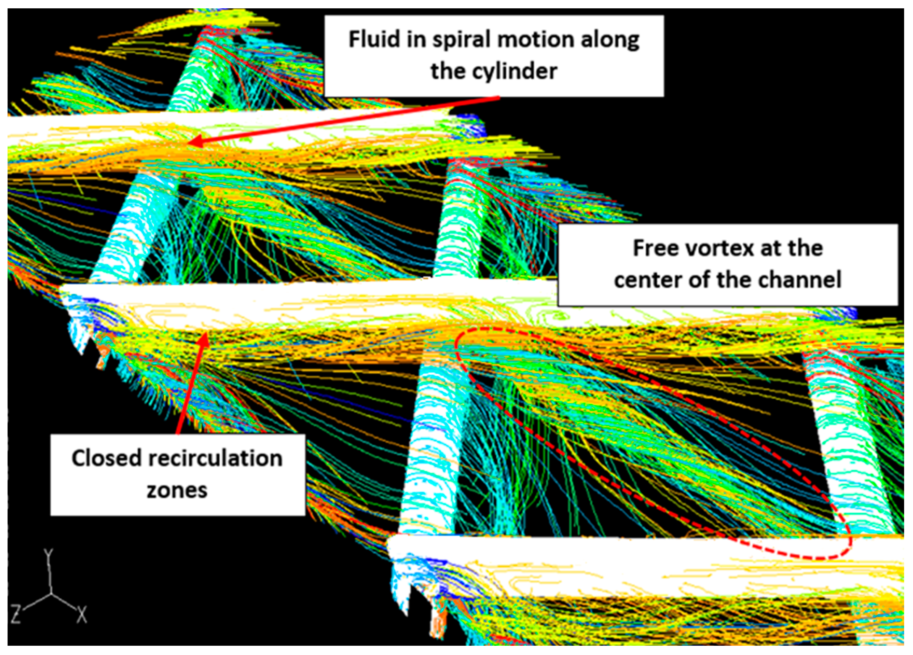
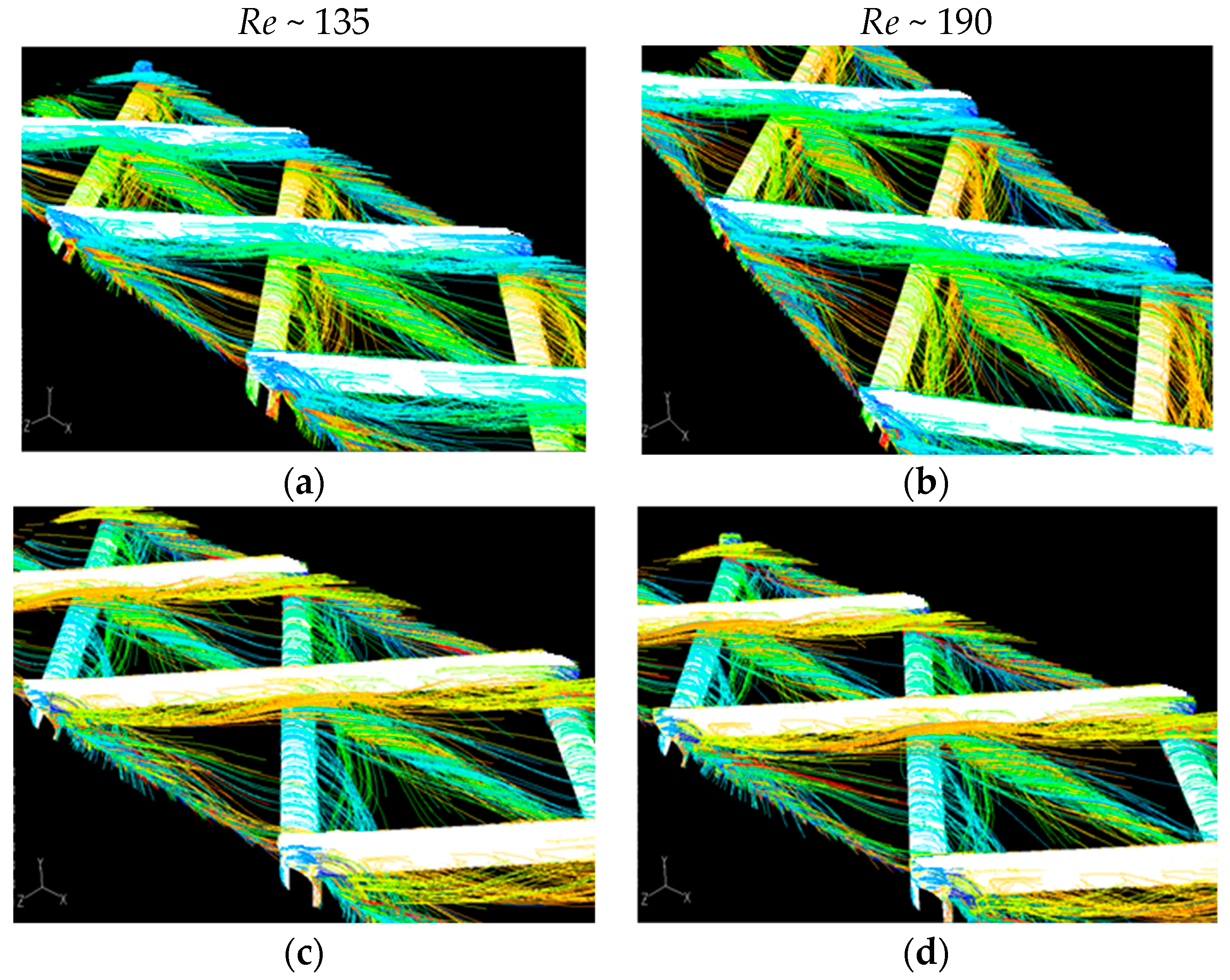
For all the cases considered, simulations reveal some generic qualitative flow features which are very similar with those of the (fouling-free) base case [20]. Typical instantaneous images obtained from the numerical simulations are included in Figure 2 and Figure 3; the chromatic scale of local velocities is such that the highest and smallest velocities are designated by red and purple color, respectively. In Figure 2, fluid-particle path lines are shown, for the Case 2 of this study where the fouling-layer thickness h is 5% of the spacer-filament diameter, D. As in the fouling-free case, the main flow feature is a free vortex along the diagonal of the unit cell, i.e., approximately aligned with the main flow direction. This vortex, which seems to be enhanced as the channel-gap is reduced and the Re number increases (Figure 3), results from interaction/merging of two different flow streams entering the unit cell from different directions, thus creating a surface of high shear in the vicinity of the horizontal mid-plane of the unit cell. A second characteristic is the flow separation in the downstream side of each cylindrical filament, which is due to the three-dimensional nature of the flow and the component of pressure gradient parallel to the cylinders; this leads to spiral paths along the respective cylinder directions, as shown in Figure 2. Another feature, also evident in Figure 2, is the presence of closed recirculation regions attached to each cylinder, which result from the interaction of the vortices along the cylinder with the central free vortex.
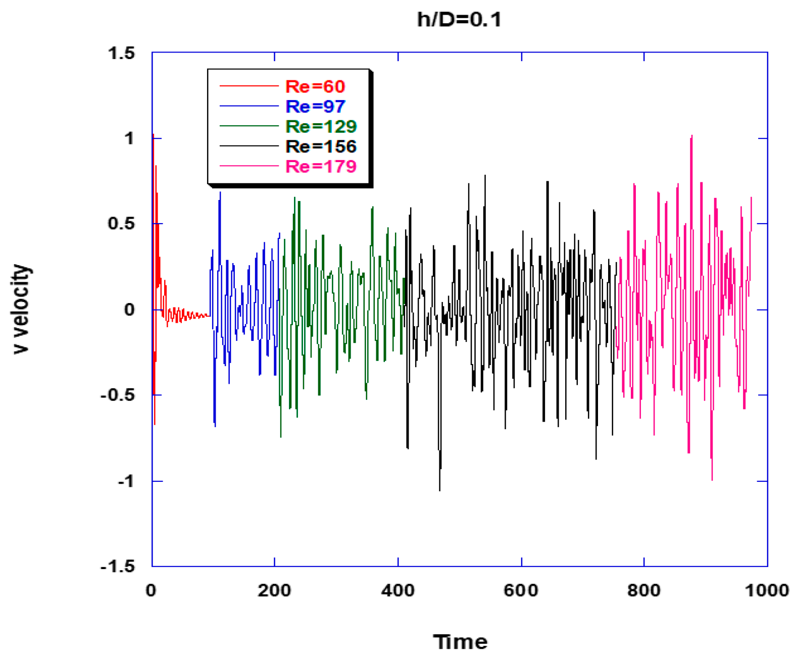
It is of considerable interest to examine the effect of channel-gap reduction on the transition to unsteady flow, which obviously impacts on wall shear-stress fluctuations, wall mass transfer and concentration polarization. For the reference (no fouling) case, a thorough data analysis regarding the evolving flow field, including spectra of fluctuating wall velocities and shear stresses, is presented by Koutsou et al. [20]. Among other results, it is shown there that the transition to unsteady flow occurs at rather low Re numbers; i.e., in the narrow range 35 to 45, for the studied fairly broad range of spacer geometric parameters. The present results confirm the general trends observed previously [20]; moreover, as one might have expected, the reduction of gap tends to stabilize the flow. Indeed, as Figure 4 indicates (as well as other data not presented here), the transition to unsteady flow occurs at increasing Re number with decreasing channel gap 2D′ (or increasing h). For a fouling-layer thickness h/D = 0.1 (Figure 4), the time series of transverse velocity component v (plotted for increasing Re numbers), clearly suggests that flow unsteadiness appears above Re = 60; with increasing Re number, the transitional unsteady flow [20] tends to become chaotic and turbulent (at high Re).
3.2. Effect of Channel-Gap Reduction on Pressure Drop
A key objective of the present simulations is to determine the effect of a uniform fouling layer on the pressure drop in the retentate channels. The pressure drop correlation for the “clean channel” (h = 0) and fixed geometric spacer parameters (β, L/D) has already been reported [20] and it has the form: f = 0.85Re–0.19 The present study also aims to incorporate into the aforementioned correlation the effect of a uniform fouling-layer thickness (h/D) by an appropriate modification.
Figure 5 depicts the calculated pressure drop versus flow rate, for fouling-layer thickness from 2.5–10% of the filament diameter D, in comparison with the corresponding data of the clean channel case (h/D = 0). The flow rate Q corresponds to the computational domain (Figure 1a), for the range of superficial (or cross-flow) velocities U of practical interest, i.e., ~0.10 to ~0.20 m/s. It is clear from Figure 5 that (as expected) the pressure drop tends to increase with increasing thickness h and the corresponding channel-gap reduction. The constriction of the free flow, due to reduction of the effective gap (H−2h) of the retentate channel, results in increased mean velocity, thus leading to increased pressure loss due to increased contributions of shear stresses and form drag. It should be noted that experimental data, presented elsewhere [20], on pressure drop corresponding to the clean channel case (h/D = 0), for spacer with L/D = 8 and β = 90°, show very good agreement with the respective results of numerical simulations, thus providing support to the validity of the latter.
The data plotted in Figure 5 are made dimensionless by defining as follows the friction factor f, where U is the superficial cross-flow velocity corresponding to the effective gap of the retentate channel (H − 2h):
The computational results in dimensionless form, included in Figure 6, suggest that the dependence of friction factor f on Re number, for all the values of fouling-layer thickness h examined, is quite close to that holding for the no-fouling geometry. However, the friction factor computed on the basis of D′ (D′ = D − h) tends to decrease systematically with increasing fouling-layer thickness, which should be accounted for in an appropriate correlation.
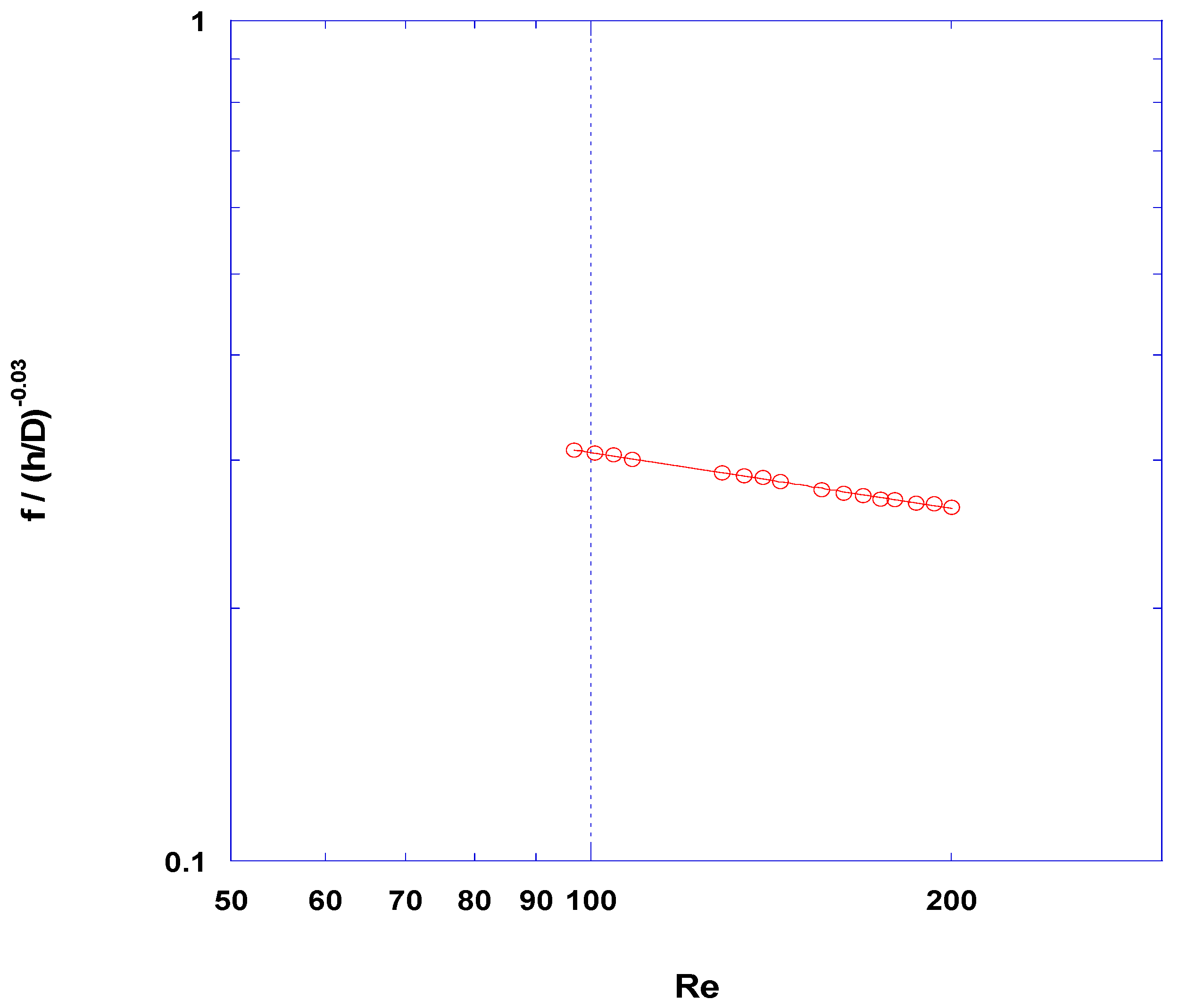
As shown in Appendix A, the data of friction factor f, plotted versus the ratio h/D (Figure A1), show practically the same dependence of f on the ratio h/D (with an exponent approx. −0.03) for all the cases examined in this work. Therefore, the new data may be correlated by a function of the form (Figure A2):
This expression is similar to the correlation for the “no-fouling” case (i.e., f = 0.85Re−0.19), obtained in a previous campaign [20], which only slightly differs in the Re dependence. As outlined in the Appendix, this close similarity allows the following correlation (of a somewhat different form), also covering the base case (h = 0), to be obtained:
where Re is defined as in Equation (2a). It should be pointed out that this expression (applicable in the range (h/D) = 0 to ~0.15), can be conveniently incorporated in comprehensive dynamic process simulators (e.g., [24]) which are under development. Finally, it is interesting to note that the results of this study (data in Figure 5 and the respective correlation, Equation (5)) show that for a 10% reduction of the spacer-filled channel gap (i.e., (h/D) = 0.1) the pressure drop increase amounts to ~26%, compared to the base case.
3.3. Effect of Fouling-Layer Thickness on Shear Stress at the Membrane Surface
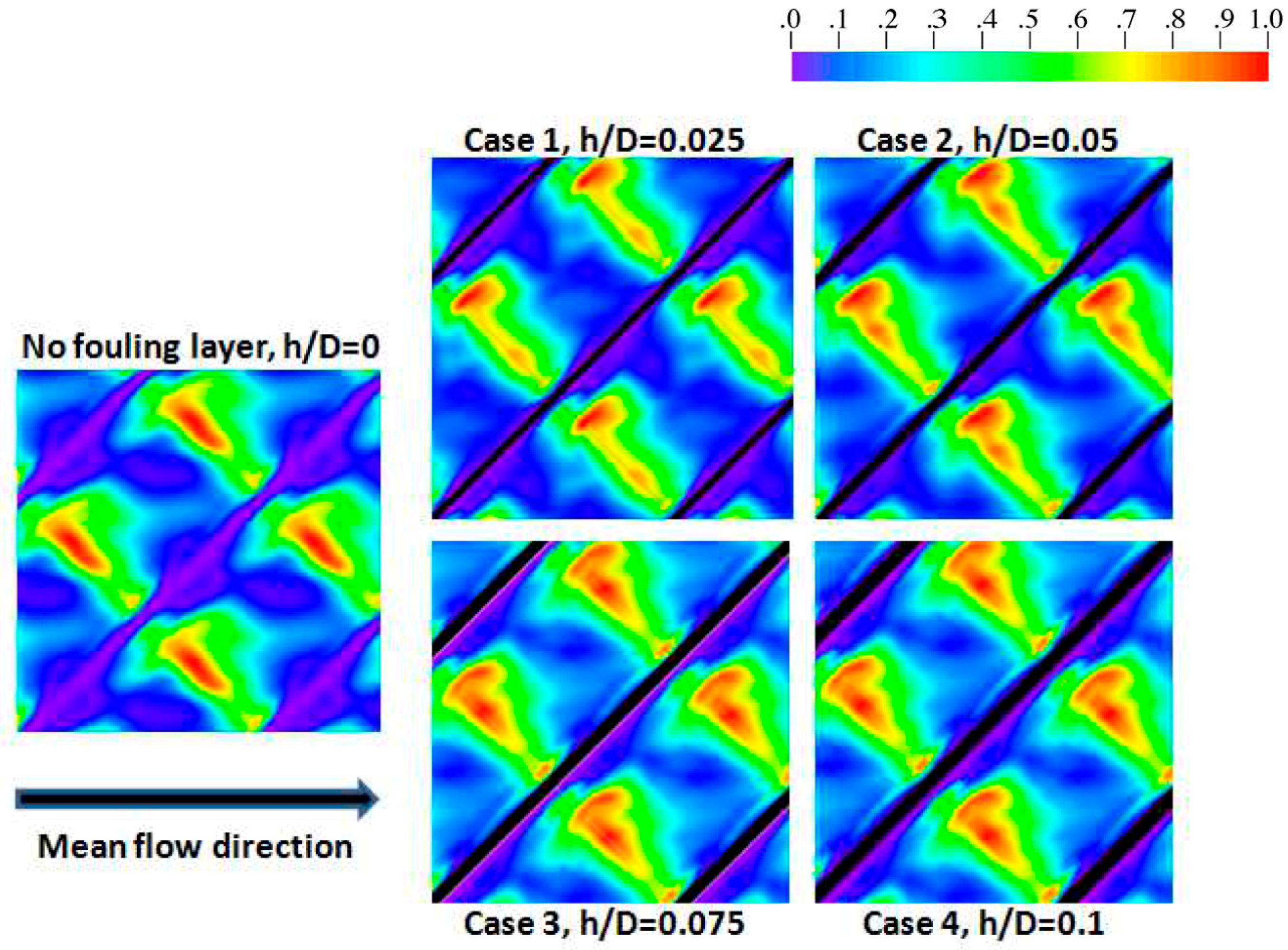
From the detailed numerical flow simulations, dimensionless time-averaged wall shear stresses have also been obtained, which are directly related to the mass-transfer coefficients in the spacer-filled membrane channels. In Figure 7, typical results are depicted regarding the distribution of time-averaged shear stress on the membrane surface. The images of the spatial shear stress distributions included in Figure 7 (for approximately the same Reynolds number) correspond to fouling-layer thickness in the range 0–10% of the spacer-filament diameter. Purple and red colors represent minimum and maximum shear-stress values, respectively. One observes in Figure 7 that, for an increasing uniform fouling-layer thickness h (in the range of parameter values studied), the distribution of shear stresses is qualitatively very similar, for all the cases examined; however, as expected, the high-shear regions tend to increase with increasing h. Shear stresses are at a minimum (zero) at the contact of linear strips of spacer filaments with the surfaces of the retentate channel. High shear-stress values are observed at the narrow regions between the spacer filaments and the channel walls, where the velocity is increased. The maximum shear-stress values are attributed to the recirculation zones (marked in Figure 2), the presence of which results in further constriction of the fluid (as shown in Figures 20 and 21 of [20]), thus intensifying the stress at that location of the retentate channel.
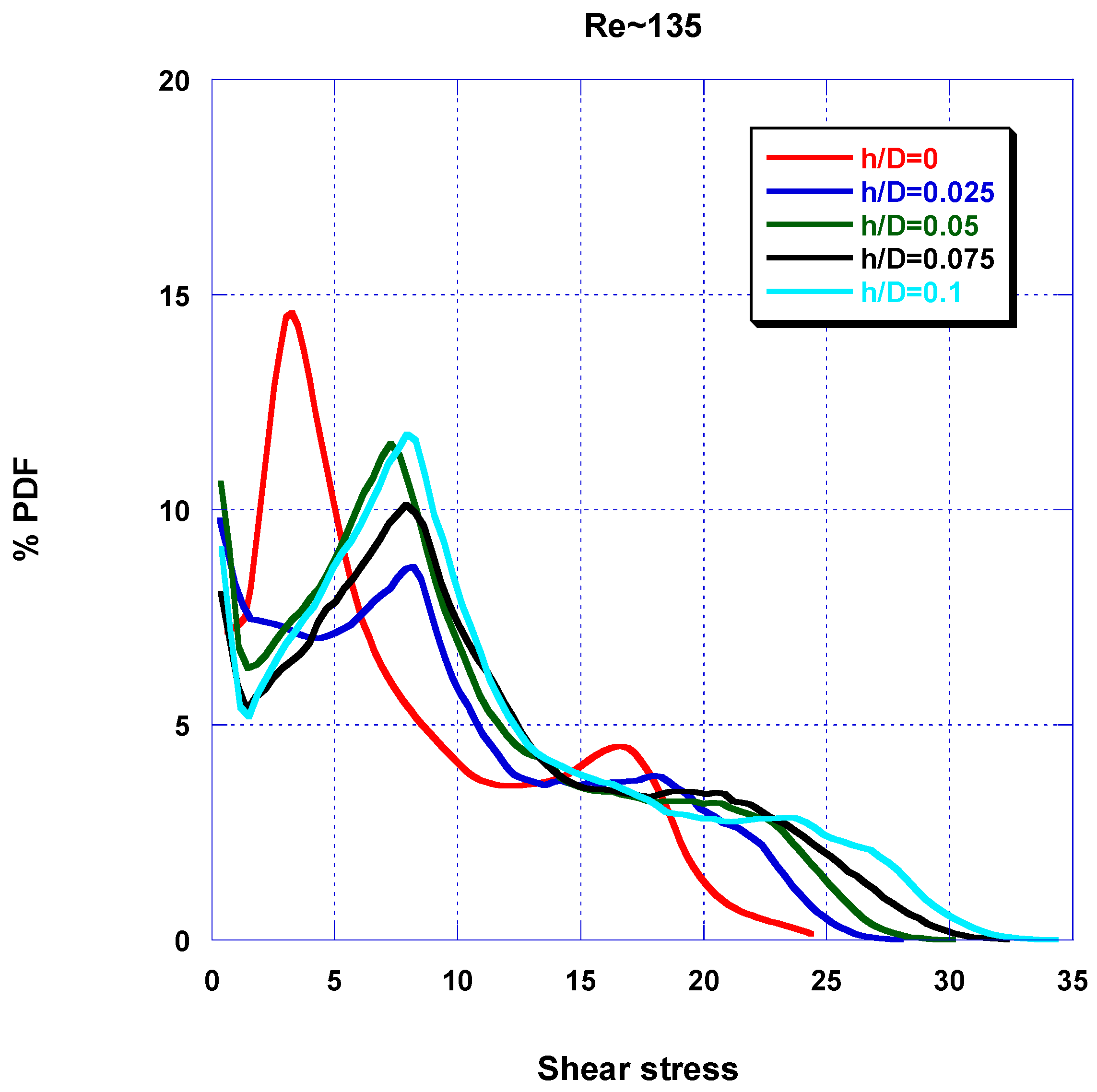
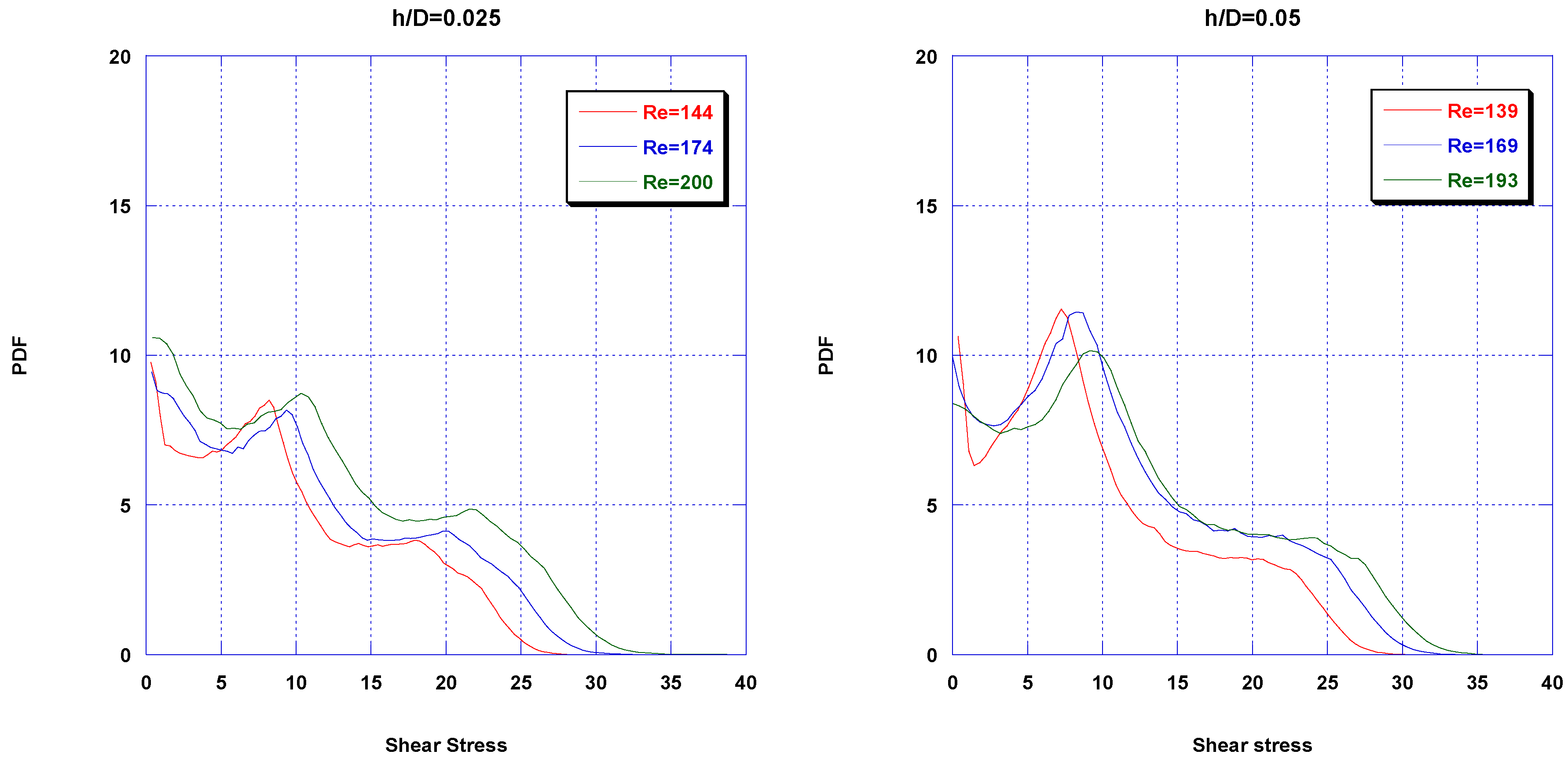
Quantitative comparison of results for the “no-fouling” case with those corresponding to cases of various fouling-layer thicknesses h, shown in Figure 8, suggests that as thickness h increases, the distribution of the local shear stresses tends to become more uniform (with elimination of a secondary peak) and somewhat broader, extending toward higher values. This is attributed to the increased mean velocity, due to the reduction of the effective gap (H−2h) of the channel, which results in increased velocities close to the retentate channel walls, with concomitant increase of the wall shear stress. This is also evident in the data of Figure 9, where more uniform and broader shear-stress distributions prevail, toward higher values with increasing Re number. Additionally, the increased wall shear stresses with increasing h contribute to the computed increase of pressure drop in the channel.
3.4. Effect of Fouling-Layer Thickness on Mass Transfer
Mass transfer simulations of the spacer-filled channel were carried out in the Schmidt number range 1–100, which allowed a modest extrapolation to greater Sc numbers in correlating the numerical data. It is noted that for the systems of practical interest (i.e., saline waters), the Schmidt number is of order 103 leading to very thin concentration boundary layers at channel walls, which require a very fine grid at the wall, and entail increased computational load, exceeding the capabilities of available computational facility. Simulations of mass transfer were performed for the geometries listed in Table 1, i.e., for fouling-layer thickness h between 2.5–10% of the spacer-filament diameter.
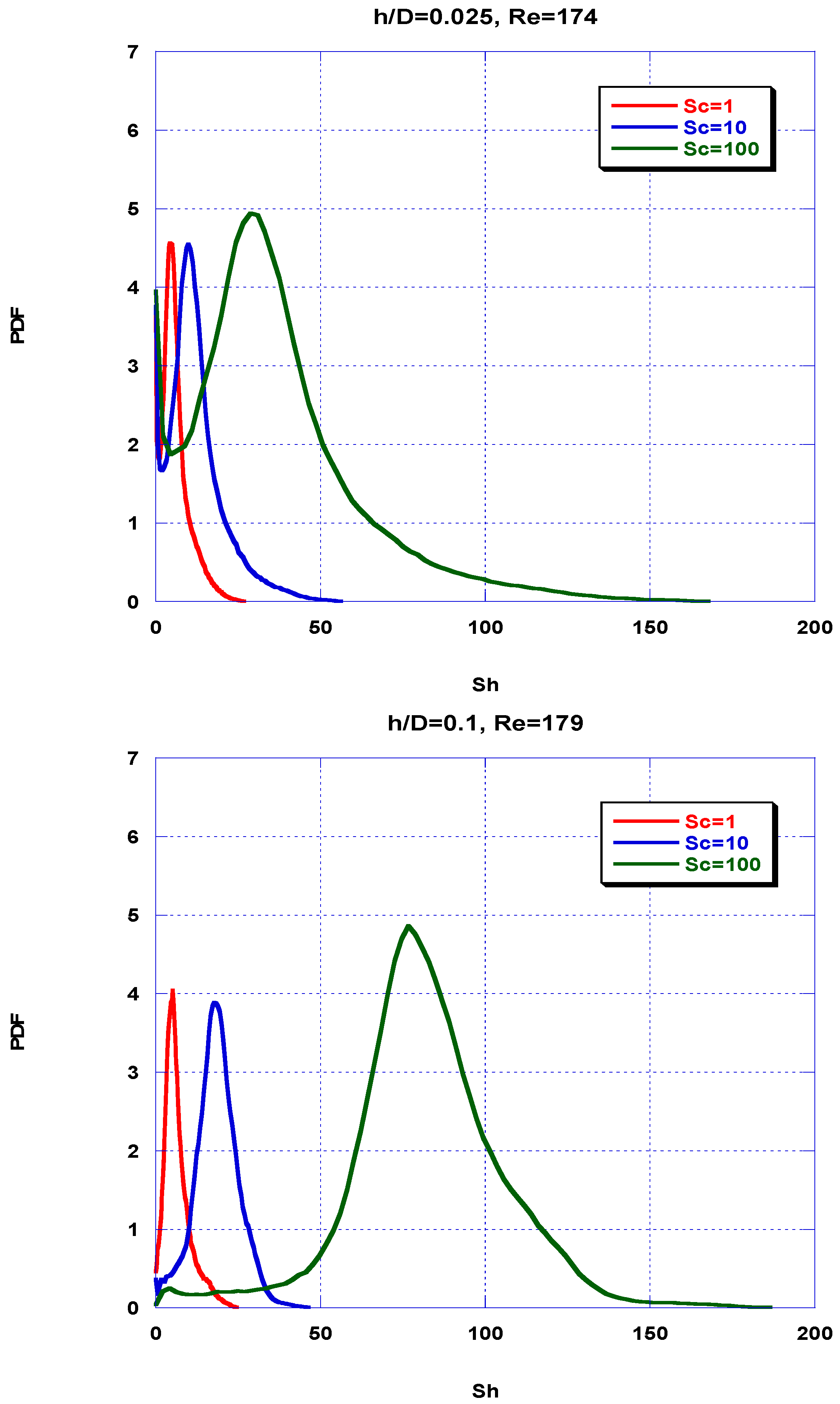
Figure 10, depicts predicted distributions of local time-averaged Sherwood number Sh for fouling-layer thickness (h/D) = 0.025 and 0.10 in the Sc number range 1–100. Sh number distributions are generally skewed to the right; there is a significant percentage of near-zero values, due to the contact lines/areas of spacer filaments with the membrane surfaces comprising the retentate channel, and the nearly stagnant flow regions near and along these lines. At greater Sc number (leading to reduced boundary-layer thickness), the Sh number distributions tend to become wider. It is also interesting to note that, in the data plotted in Figure 10 (as well as in those not shown here for economy of space), with increasing thickness h/D the distributions tend to become normal due to the reduced proportion of near zero values; this reflects the change of flow-field geometry and the apparent reduction of almost stagnant flow zones at increased h/D. However, the reduction (with increasing h/D) of Sh number values at the high-value end of the distribution may be partly due to the non-dimensionalization; i.e., as shown in the Sh number definition (Equation (2c) involving the product (kD′), a likely increase of local mass-transfer coefficient k (at reduced D′) is apparently smaller than the reduction of D′ itself.
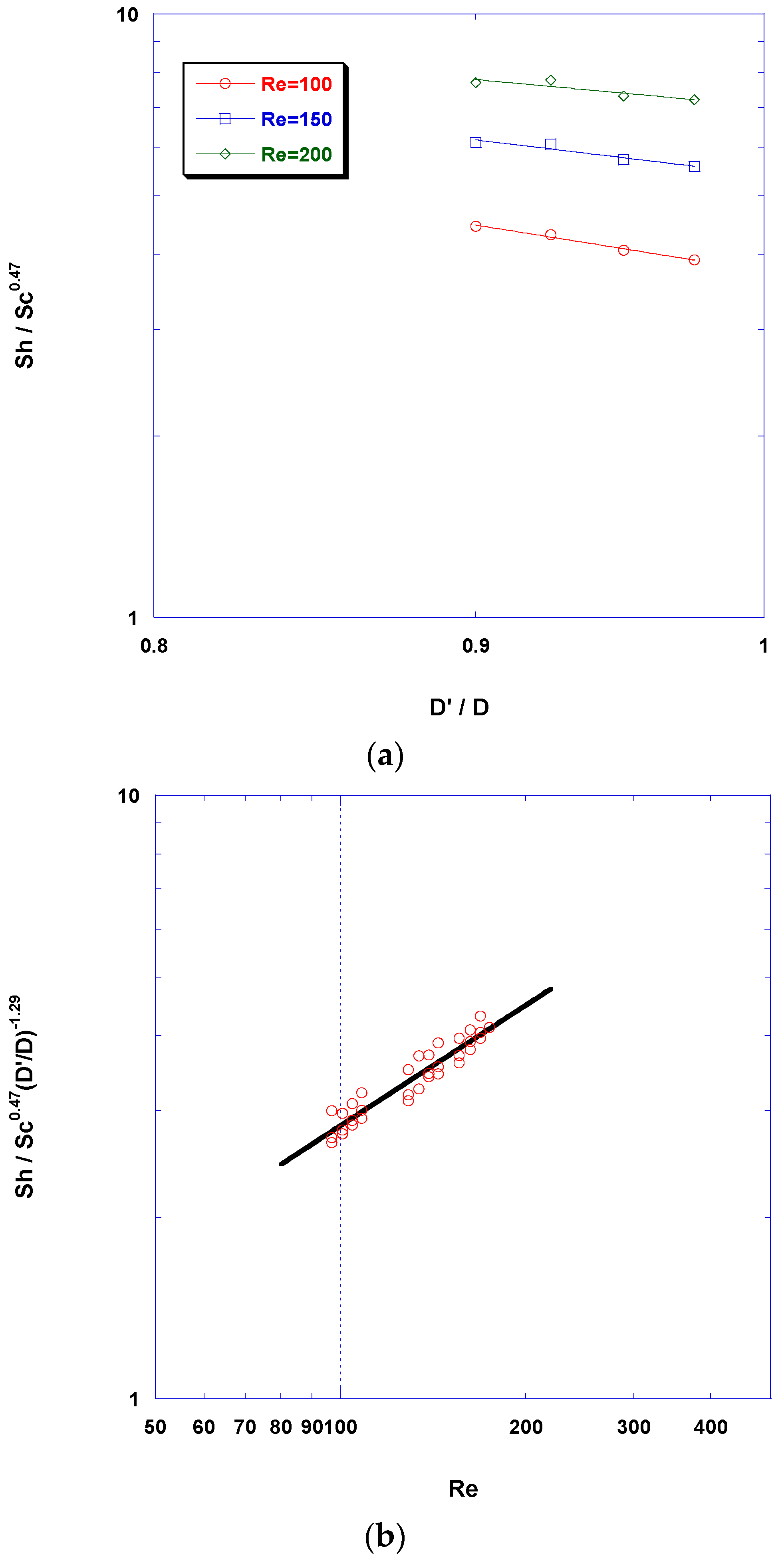
As in the case of pressure drop, a key objective of the mass-transfer simulations is to develop a sound correlation of Sh number with fouling-layer thickness, including the Re and Sc number dependencies. In Figure A4 (Appendix B), the measured space and time-average Sherwood number is plotted as a function of Sc number, for the range of Reynolds numbers and fouling-layer thickness examined in this work. These data sets, show that for all fouling-layer thicknesses tested, the Sc dependence of mean Sherwood number is practically constant, and equal to ~0.47.
This similar dependence of Sh on Sc allows re-plotting the data in terms of Sh/Sc0.47 versus the ratio D′/D, to determine the D′/D dependence. The results presented in Figure 11a show that for various Re numbers between 100 and 200 (where the commercial spiral-wound elements usually operate), there is similar dependence on the ratio D′/D with an exponent close to −1.29 in all cases; moreover, as one would expect, the space average Sh number tends to increase with gap reduction. Therefore, the dimensionless quantity [Sh/Sc0.47(D′/D)−1.29], plotted versus Re number in Figure 11b, allows a fair correlation to be obtained:
However, this expression can be recast (employing a Taylor expansion) in the following form to facilitate applications (including modeling) that involve explicitly the thickness h:
Finally, it should be noted that the results of this study (and the respective correlation in Equation (7)) show that for a 10% reduction of the spacer-filled channel gap (i.e., (h/D) = 0.1) the space-average mass-transfer coefficient increases by approximately 30%, compared to the base case.
It should be pointed out that experimental data (at high Sc) and similar numerical results (for spacer type L/D = 8, β = 90°), obtained by the present authors [21] with the reference unobstructed channel geometry (h = 0), are well correlated by the following expression:
which is quite close to the above correlation (Equation (7)) regarding the Sh dependence on Sc and Re numbers. This close similarity provides a validation of the numerical results presented herein.
4. Discussion
Prediction from first principles of the spatial-temporal flow-field evolution, under simultaneous development of fouling layers, throughout the desalination membrane sheets (in spacer-filled narrow channels), is a formidable task, considered impossible at present. Aiming to develop a sound approximate method to tackle this problem, by un-coupling fouling-layer evolution from the fluid mechanical problem, this study considers the effect of uniformly developing fouling layers on fluid dynamics and mass transfer in spacer-filled channel walls. The assumption is made of fouling-layer uniformity at the “unit cell” spatial scale, realizing that it may be realistic only for some types of foulants but not for all of them. Indeed, as outlined in the Introduction, common foulants such as polysaccharides (including extracellular polymeric substances (EPS) in biofilms) seem to develop fairly coherent gels on membranes [8,32], impossible to detach by fluid-shear forces prevailing during desalination [32], thus prone to be fairly uniform. However, for other foulant types such as humic acids alone, the fouling-layer thickness in spacer-filled channels appears to be non-uniform [21]. Similarly, it is reported that there is non-uniform layer thickness in biofouling experiments [34]. However, the simplifying assumption of thickness uniformity made here for rather thin layers is considered realistic in efforts to model and quantify channel-gap reduction effects on flow and convective mass transfer at a large spatial scale; this assumption is also made in other, similar studies [5]. Obviously, the topic of fouling-layer development at small as well as large spatial scales merits further attention.
The results obtained here, including the correlations for pressure drop and mass-transfer coefficient, are readily applicable to the case of gap reduction of spacer-filled narrow channels (by causes other than fouling) in order to obtain reliable estimates of the respective quantities. Such gap reduction, attributed to feed-channel deformation in the SWM-module fabrication, is reported by membrane manufacturers [1], but no means to accurately determine key parameters such as pressure drop are available for such cases to the authors’ best knowledge.
The spacer geometric parameters employed in this study (L/D = 8, β = 90°), closely correspond to the commercial “28 mil” spacer, where L/D ≈ 8.5. However, the similarity of the flow field and the dimensionless quantities employed, in the simulations and in the developed correlations, permit the use of the new results and correlations to the others frequently encountered in practice-spacer types, i.e., “26 mil” and “34 mil”, where L/D ≈ 8.9 and ~8.0, respectively.
The correlations obtained in this work can find practical use in parametric studies and in various benchmarking exercises. However, the usefulness of the new results and correlations on developing and/or improving comprehensive dynamic simulators of RO desalination plant performance, which is pursued by the present authors [4,6,24], is of particular interest and will be briefly assessed. The effect of even a modest reduction of channel gap on the pressure drop ΔP/Δx appears to be quite important, as discussed in the foregoing section; therefore, the ΔP/Δx correlation, including the channel-gap correction, can be properly adapted to SWM performance models and simulators (e.g., [22,24]). Regarding the mass-transfer correlation, Equations (6) or (7) show that the channel-gap reduction is also significantly affecting the mass-transfer coefficient k, even though there is some scatter (Figure 11b) in numerical-data correlation due to the fact that the exponent on D′/D is weakly dependent on Re number whereas a constant average value is chosen (−1.29). However, it is shown below that even a rough estimate of dissolved species mass-transfer coefficient due to fluid convection at the membrane surface (k) is sufficient in modeling species mass transfer in the presence of a fouling layer, because k during the desalination process tends to contribute insignificantly to the overall mass transfer Kt, compared to cake-induced mass-transfer reduction. To demonstrate the significance of the latter effect, one should consider the total mass-transfer coefficient, which is given as:
where De is the species effective diffusion coefficient in the fouling layer. Multiplying both sides of Equation (9) by D/Dc and substituting the correlation (Equation (7)) for k in the form kD/Dc = Sho(1 + az) where z = h/D and a = 1.65 one obtains:
Here E = De/Dc is the ratio of the effective diffusivity in the fouling layer over the species diffusivity in the liquid phase. A comparison of the terms at the right-hand side of Equation (10) clearly shows that (as the fouling layer grows) the increase of mass transfer due to convection (k) contributes very little to the total mass-transfer variation. In particular, using the ratio αE/Sho, one can show, for typical values of the parameters involved, that only 1–2% of the total mass-transfer variation is due to an increase of coefficient k, because of channel-gap reduction; therefore, the accuracy in the computation of k does not affect the estimates for total mass-transfer coefficient Kt, needed in comprehensive desalination-process modeling.
It is evident from this study that the reliable prediction of increasing fouling-layer thickness h and of transport phenomena related to fouling-layer properties (as a function of desalination-system parameters and foulants) is critical in the development of a sound dynamic process simulator [24]. Therefore, future work should be focused on measuring, understanding and modeling fouling-layer development. Significant efforts to understand, monitor and predict developing fouling-layer properties, including h, have already been reported (e.g., [8,9,35,36,37,38]) under idealized conditions. Furthermore, in the context of hydrodynamics and fouling evolution in spacer-filled channels, investigating the effect of the detailed geometry and filament shape of the spacer is of high priority. The present results with the common spacer type, comprised of unwoven filaments of cylindrical shape, for which there is extensive literature and experimental data, provide a kind of base case.
5. Conclusions
This study is mainly motivated by the need to simulate the time-varying flow field in spacer-filled desalination membrane channels, caused by the development of fouling layers on the membranes that modify the flow-field geometry and affect the transport phenomena at the membrane surface. As the complete dynamic problem of flow and mass transfer, under the simultaneous growth of fouling layers, cannot be tackled at present due its complexity, a simplified approach is pursued whereby at a small spatial scale the fluid dynamics and mass transfer are uncoupled from the fouling-layer growth process. Therefore, fluid dynamics and mass transfer are studied herein in detail for a spacer-filled narrow channel whose geometry is altered by a developed uniform fouling layer of thickness h on the membranes. For this purpose, 3D direct numerical simulations are performed (in a restricted spatial domain) employing the “unit cell” approach where periodic boundary conditions are applied. The specific thickness values considered are in the range 2.5–10% of the cylindrical spacer filament diameter D, which covers conditions of practical significance. The geometric parameters of the spacer employed in the simulations correspond to those of commonly encountered commercial spacers.
The new results reveal that the qualitative characteristics of the altered flow field in the spacer-filled channel (of reduced gap due to fouling) are very similar to those of the reference geometry, i.e., with no gap reduction. The main flow characteristics include a free vortex along the diagonal of the unit cell (roughly in the main flow direction) as well as spiral vortices and recirculation zones downstream of each spacer filament. It is interesting, however, that the gap reduction apparently tends to stabilize the flow and extend the transition to unsteady flow to somewhat greater Re numbers. As expected, for a given flow rate, pressure drop and time-averaged wall shear stress as well mass-transfer coefficient k tend to significantly increase with increasing fouling-layer thickness h due to the reduced effective channel-gap, leading to increased flow velocities.
Useful correlations are obtained from the numerical data on friction factor f and overall average Sh number, which exhibit similar functional dependence of f and Sh on Re and Sc numbers to the reference case of the unobstructed channel (h = 0). A noteworthy feature of these correlations is the incorporation of the effect of channel-gap reduction, which allows predictions in the range of fouling-layer thickness (h/D) = 0–0.10. The proposed correlations, in addition to other uses, can be employed tο improve steady-state models and develop realistic dynamic models simulating the operation of SWM modules and RO/NF plants.
Author Contributions
Chrysafenia P. Koutsou performed the numerical simulations, collaborated in the development of correlations and drafted the manuscript. Anastasios J. Karabelas collaborated in planning the study, in developing the correlations and in editing/finalizing the manuscript. Margaritis Kostoglou collaborated in the planning and in modeling aspects of the study.
Conflicts of Interest
The authors declare no conflict of interest.
Appendix A. Pressure-Drop Correlation Applicable to Reduced Channel Gap
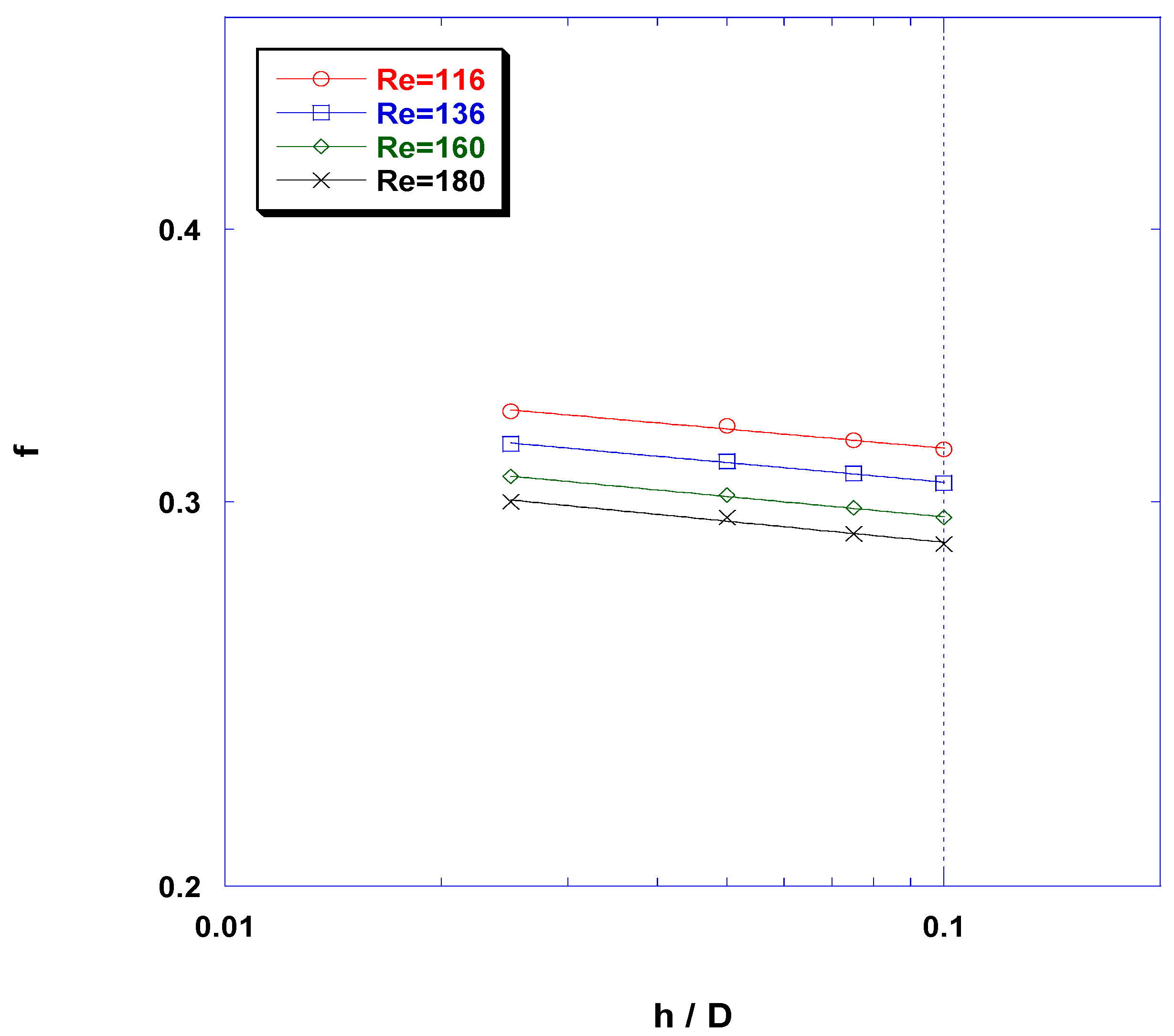
Data of friction factor f, as a function of the ratio h/D, plotted in Figure A1, show practically the same dependence of f on the ratio h/D (with an exponent approx. −0.03) for all the cases examined in this work. This particular dependence of dimensionless pressure drop on the ratio h/D allows re-plotting the data in terms of f/(h/D)−0.03 versus Re, in order to determine the Re number dependence; the results are presented in Figure A2 and a correlation thus obtained is of the form:
It will be noted, by comparing this correlation [Equation (A1)] with the corresponding correlation for the “no-fouling” case (f = 0.85Re−0.19), obtained in a previous campaign [20], that they are very similar; i.e., with the same pre-exponential factor and only a slight difference in the Re dependence. As outlined in the following, this close similarity allows the development of a correlation of a somewhat different form, which will also cover the base case (h = 0), thus facilitating its application in practice as well as its inclusion in desalination-process simulators (e.g., [22,24]).
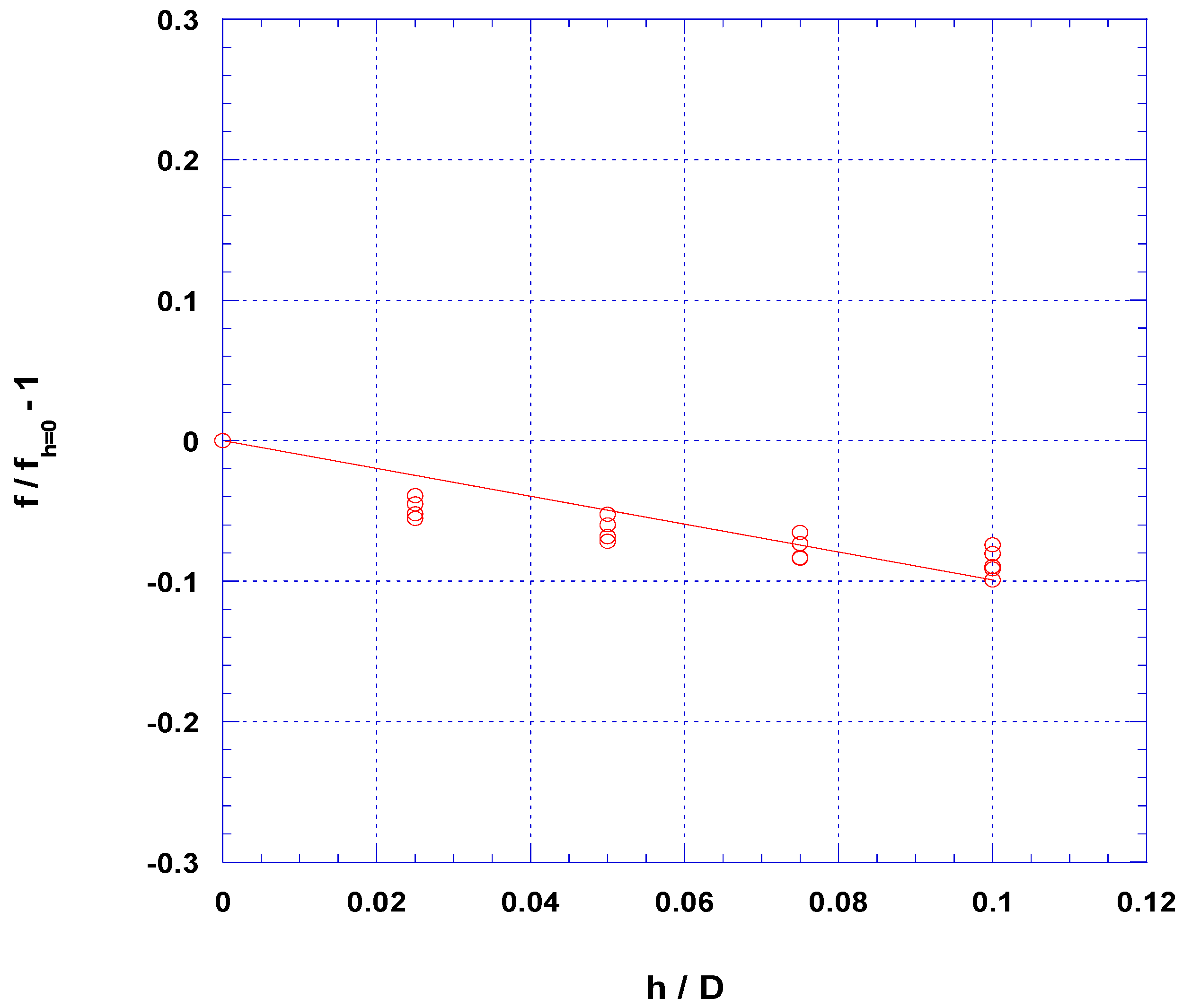
Figure A1.
Dimensionless pressure drop (friction factor) as a function of the ratio h/D.

By plotting the dimensionless quantity [(f/fh = 0) − 1] versus the fouling-layer thickness (h/D), one obtains a practically linear dependence on the ratio h/D (Figure A3), which leads to the following correlation:
where Re is defined in Equation (3b).
Figure A2.
Dimensionless pressure drop (modified friction factor) as a function of the ratio h/D and Re number. Correlation: f = 0.85(h/D)−0.03Re−0.22.
Figure A2.
Dimensionless pressure drop (modified friction factor) as a function of the ratio h/D and Re number. Correlation: f = 0.85(h/D)−0.03Re−0.22.

Figure A3.
Variation of expression [(f/fo)−1] with dimensionless fouling-layer thickness.
Appendix B. Mass-Transfer Correlation Applicable to Reduced Channel Gap
In Figure A4 the measured space and time-average Sherwood number is plotted as a function of Sc number for the range of Reynolds numbers and fouling-layer thickness examined in this work. These data sets (as well as other similar data for h/D = 0.025 and 0.075 not included here), show that for all fouling-layer thicknesses tested, the Sc dependence of mean Sherwood number is practically constant, and equal to ~0.47. This similar dependence of Sh on Sc allows re-plotting the data in terms of Sh/Sc0.47 versus the ratio D′/D, to determine the D′/D dependence, toward the development of a generalized correlation.
Figure A4.
Time and space-average Sh number on the membrane surface as a function of Sc number for (a) h/D = 0.05; and (b) h/D = 0.10.
Figure A4.
Time and space-average Sh number on the membrane surface as a function of Sc number for (a) h/D = 0.05; and (b) h/D = 0.10.

References
- Johnson, J.; Busch, M. Engineering aspects of reverse osmosis module design. Desalin. Water Treat. 2010, 15, 236–248. [Google Scholar] [CrossRef]
- Karabelas, A.J. Key issues for improving the design and operation of membrane modules for desalination plants. Desalin. Water Treat. 2014, 52, 1820–1832. [Google Scholar] [CrossRef]
- Karabelas, A.J.; Koutsou, C.P.; Kostoglou, M. The effect of spiral wound membrane element design characteristics on its performance in steady state desalination—A parametric study. Desalination 2014, 332, 76–90. [Google Scholar] [CrossRef]
- Koutsou, C.P.; Karabelas, A.J.; Kostoglou, M. Membrane desalination under constant water recovery—The effect of module design parameters on system performance. Sep. Purif. Technol. 2015, 147, 90–113. [Google Scholar] [CrossRef]
- Hoek, E.M.V.; Allred, J.; Knoell, T.; Jeong, B.-H. Modeling the effects of fouling on full-scale reverse osmosis processes. J. Membr. Sci. 2008, 314, 33–49. [Google Scholar] [CrossRef]
- Kostoglou, M.; Karabelas, A.J. A mathematical study of the evolution of fouling and operating parameters throughout membrane sheets comprising spiral wound modules. Chem. Eng. J. 2012, 187, 222–231. [Google Scholar] [CrossRef]
- Tang, C.Y.; Chong, T.H.; Fane, A.G. Colloidal interactions and fouling of NF and RO membranes: A review. Adv. Colloid Interface Sci. 2011, 164, 126–143. [Google Scholar] [CrossRef] [PubMed]
- Karabelas, A.J.; Sioutopoulos, D.C. New insights into organic gel fouling of reverse osmosis desalination membranes. Desalination 2015, 368, 114–126. [Google Scholar] [CrossRef]
- Sim, S.T.V.; Taheri, A.H.; Chong, T.H.; Krantz, W.B.; Fane, A.G. Colloidal metastability and membrane fouling—Effects of cross flow velocity, flux, salinity and colloid concentration. J. Membr. Sci. 2014, 469, 174–187. [Google Scholar] [CrossRef]
- Johannink, M.; Masilamani, K.; Mhamdi, A.; Roller, S.; Marquardt, W. Predictive pressure drop models for membrane channels with non-woven and woven spacers. Desalination 2015, 376, 41–54. [Google Scholar] [CrossRef]
- Fimbres, G.A.; Wiley, D.E. Review of 3D CFD modelling of flow and mass transfer in narrow spacer-filled channels in membrane modules. Chem. Eng. Process. Process Intensif. 2010, 49, 759–781. [Google Scholar] [CrossRef]
- Karode, S.K.; Kumar, A. Flow visualization through spacer filled channels by computational fluid mechanics, I. Pressure drop and shear stress calculations for flat sheet geometry. J. Membr. Sci. 2001, 193, 69–84. [Google Scholar] [CrossRef]
- Schwinge, J.; Wiley, D.E.; Fletcher, D.F. A CFD study of unsteady flow in narrow spacer-filled channels for spiral-wound membrane modules. Desalination 2002, 146, 195–201. [Google Scholar] [CrossRef]
- Geraldes, V.; Semio, V.; de Pinho, M.N. Hydrodynamics and concentration polarization in NF/RO spiralwound modules with ladder-type spacers. Desalination 2003, 157, 395–402. [Google Scholar] [CrossRef]
- Schwinge, J.; Wiley, D.; Fane, A. Novel spacer design improves observed flux. J. Membr. Sci. 2004, 229, 53–61. [Google Scholar] [CrossRef]
- Koutsou, C.P.; Karabelas, A.J. A novel retentate spacer geometry for improved spiral wound membrane (SWM) module performance. J. Membr. Sci. 2015, 488, 129–142. [Google Scholar] [CrossRef]
- Li, F.; Meindersma, W.; de Haan, A.B.; Reith, T. Novel spacers for mass transfer enhancement in membrane separations. J. Membr. Sci. 2005, 253, 1–12. [Google Scholar] [CrossRef]
- Picioreanu, C.; Vrouwenvelder, J.S.; Van Loosdrecht, M.C.M. Three-dimensional modeling of biofouling and fluid dynamics in feed spacer channels of membrane devices. J. Membr. Sci. 2009, 345, 340–354. [Google Scholar] [CrossRef]
- Radu, A.I.; Vrouwenvelder, J.S.; van Loosdrecht, M.C.M.; Picioreanu, C. Modeling the effect of biofilm formation on reverse osmosis performance: Flux, feed channel pressure drop and solute passage. J. Membr. Sci. 2010, 365, 1–15. [Google Scholar] [CrossRef]
- Koutsou, C.P.; Yiantsios, S.G.; Karabelas, A.J. Direct numerical simulation of flow in spacer-filled channels: Effect of spacer geometrical characteristics. J. Membr. Sci. 2007, 291, 53–69. [Google Scholar] [CrossRef]
- Koutsou, C.P.; Yiantsios, S.G.; Karabelas, A.J. A numerical and experimental study of mass transfer in spacer-filled channels: Effects of spacer geometrical characteristics and Schmidt number. J. Membr. Sci. 2009, 326, 234–251. [Google Scholar] [CrossRef]
- Kostoglou, M.; Karabelas, A.J. Comprehensive simulation of flat-sheet membrane element performance in steady state desalination. Desalination 2013, 316, 91–102. [Google Scholar] [CrossRef]
- Kostoglou, M.; Karabelas, A.J. Mathematical analysis of the meso-scale flow field in spiral wound membrane modules. Ind. Eng. Chem. Res. 2011, 50, 4653–4666. [Google Scholar] [CrossRef]
- Kostoglou, M.; Karabelas, A.J. Dynamic operation of flat sheet desalination-membrane elements: A comprehensive model accounting for organic fouling. Comput. Chem. Eng. 2016, 93, 1–12. [Google Scholar] [CrossRef]
- Yiantsios, S.G.; Sioutopoulos, D.; Karabelas, A.J. Colloidal fouling of RO membranes: An overview of key issues and efforts to develop improved prediction techniques. Desalination 2005, 183, 257–272. [Google Scholar] [CrossRef]
- Haaksman, V.A.; Siddiqui, A.; Schellenberg, C.; Kidwell, J.; Vrouwenvelder, J.S.; Picioreanu, C. Characterization of feed channel spacer performance using geometries obtained by X-ray computed tomography. J. Membr. Sci. 2017, 522, 124–139. [Google Scholar] [CrossRef]
- Hydranautics, RODESIGN, Hydranautics RO System Design Software, version 6.4 (c); Pretreatment and design limits section. 1998.
- Sioutopoulos, D.C.; Karabelas, A.J.; Yiantsios, S.G. Organic fouling of RO membranes: Investigating the correlation of RO and UF fouling resistances for predictive purposes. Desalination 2010, 261, 272–283. [Google Scholar] [CrossRef]
- Sioutopoulos, D.C.; Yiantsios, S.G.; Karabelas, A.J. Relation between fouling characteristics of RO and UF membranes in experiments with colloidal organic and inorganic species. J. Membr. Sci. 2010, 350, 62–82. [Google Scholar] [CrossRef]
- Sioutopoulos, D.C.; Karabelas, A.J. Correlation of organic fouling resistances in RO and UF membrane filtration under constant flux and constant pressure. J. Membr. Sci. 2012, 407, 34–46. [Google Scholar] [CrossRef]
- Karabelas, A.J.; Sioutopoulos, D.C. Toward improvement of methods for predicting fouling of desalination membranes - The effect of permeate flux on specific fouling resistance. Desalination 2014, 343, 97–105. [Google Scholar] [CrossRef]
- Sioutopoulos, D.C.; Goudoulas, T.B.; Kastrinakis, E.G.; Nychas, S.G.; Karabelas, A.J. Rheological and permeability characteristics of alginate fouling layers developing on reverse osmosis membranes during desalination. J. Membr. Sci. 2013, 434, 74–84. [Google Scholar] [CrossRef]
- McCarthy, M.D.; Hedges, J.I.; Benner, R. The chemical composition of dissolved organic matter in seawater. Chem. Geol. 1993, 107, 503–507. [Google Scholar] [CrossRef]
- Farhat, N.M.; Staal, M.; Siddiqui, A.; Borisov, S.M.; Bucs, S.S.; Vrouwenvelder, J.S. Early non-destructive biofouling detection and spatial distribution: Application of oxygen sensing optodes. Water Res. 2015, 83, 10–20. [Google Scholar] [CrossRef] [PubMed]
- Taheri, A.H.; Sim, S.T.V.; Sim, L.N.; Chong, T.H.; Krantz, W.B.; Fane, A.G. Development of a new technique to predict reverse osmosis fouling. J. Membr. Sci. 2013, 448, 12–22. [Google Scholar] [CrossRef]
- Gao, Y.; Haavisto, S.; Li, W.; Tang, C.Y.; Salmela, J.; Fane, A.G. Novel approach to characterizing the growth of a fouling layer during membrane filtration via optical coherence tomography. Environ. Sci. Technol. 2014, 48, 14273–14281. [Google Scholar] [CrossRef] [PubMed]
- Mairal, A.P.; Greenberg, A.R.; Krantz, W.B. Investigation of membrane fouling and cleaning using ultrasonic time-domain reflectometry. Desalination 2000, 130, 45–60. [Google Scholar] [CrossRef]
- Kujundizic, E.; Greenberg, A.R.; Fong, R.; Hernandez, M. Monitoring protein fouling on polymeric membranes using ultrasonic frequency-domain reflectometry. Membranes 2011, 1, 195–216. [Google Scholar] [CrossRef] [PubMed]
Figure 1.
(a) The basic geometry of the feed-spacer considered, indicating the 3D unit cells, and the computational domain ABCD; (b) a cross-sectional view of the spacer-filled flow channel, along the EE’ plane, with filament crossing angle β = 90°, and fouling layers of thickness h, reducing the channel gap H.
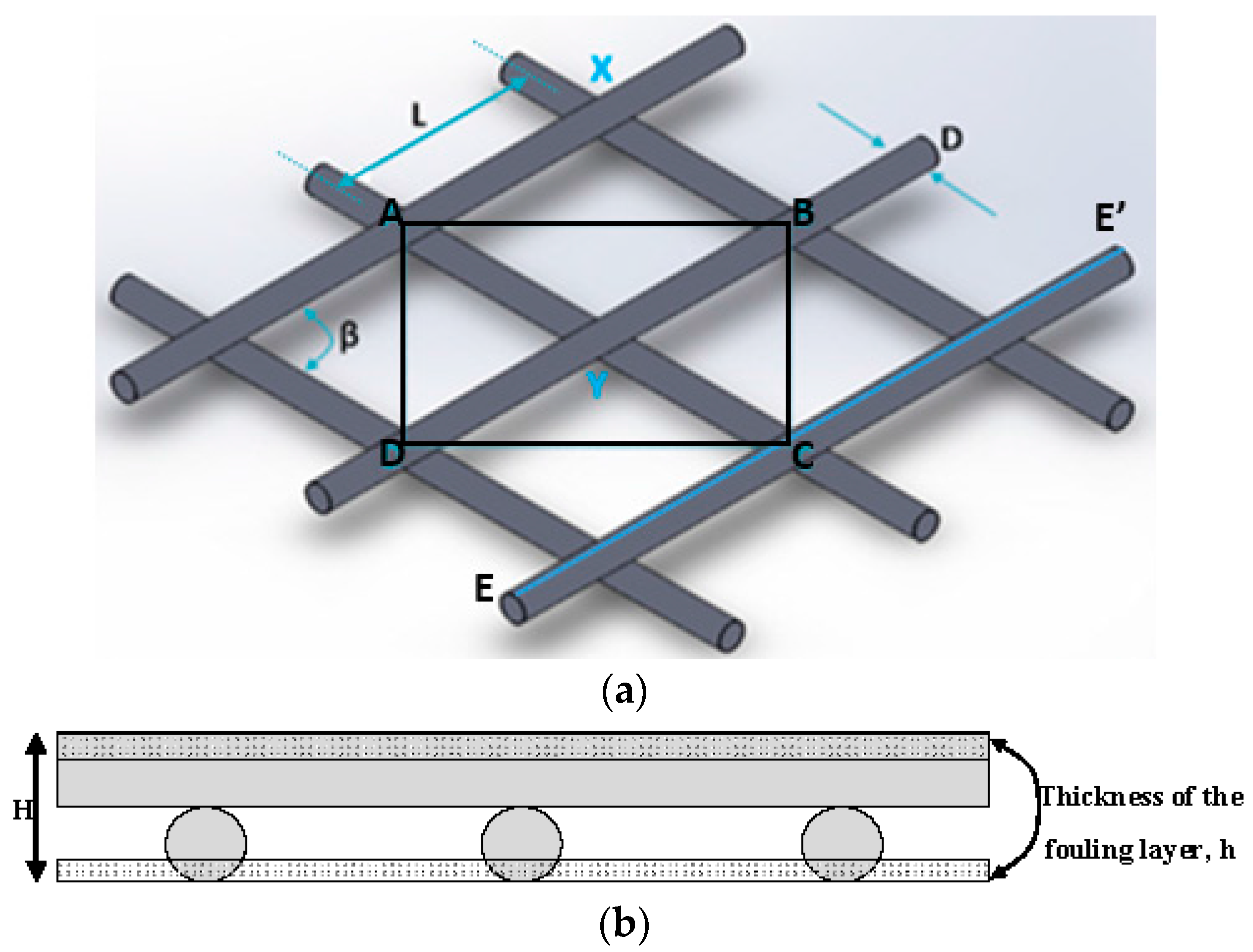
Figure 2.
An instantaneous view of fluid-particle pathlines showing the major qualitative characteristics of the flow; h/D = 0.05, Re = 193.
Figure 2.
An instantaneous view of fluid-particle pathlines showing the major qualitative characteristics of the flow; h/D = 0.05, Re = 193.

Figure 3.
An instantaneous view of fluid-particle pathlines for different fouling-layer thicknesses (a,b) h/D = 0.025; (c,d) h/D = 0.10; and Reynolds number (a,c) Re ~ 135; (b), (d) Re ~ 190.
Figure 3.
An instantaneous view of fluid-particle pathlines for different fouling-layer thicknesses (a,b) h/D = 0.025; (c,d) h/D = 0.10; and Reynolds number (a,c) Re ~ 135; (b), (d) Re ~ 190.

Figure 4.
Time series of the instantaneous normalized transverse (v) velocity component for progressively increased Re numbers; h/D = 0.1. The v-velocity component is normalized with U and the time with D′/U.
Figure 4.
Time series of the instantaneous normalized transverse (v) velocity component for progressively increased Re numbers; h/D = 0.1. The v-velocity component is normalized with U and the time with D′/U.

Figure 5.
Computational results on the effect of the fouling-layer thickness h on pressure drop in the retentate channel. The flow rate corresponds to the computational domain (Figure 1), for the range of superficial velocities U of interest.
Figure 5.
Computational results on the effect of the fouling-layer thickness h on pressure drop in the retentate channel. The flow rate corresponds to the computational domain (Figure 1), for the range of superficial velocities U of interest.
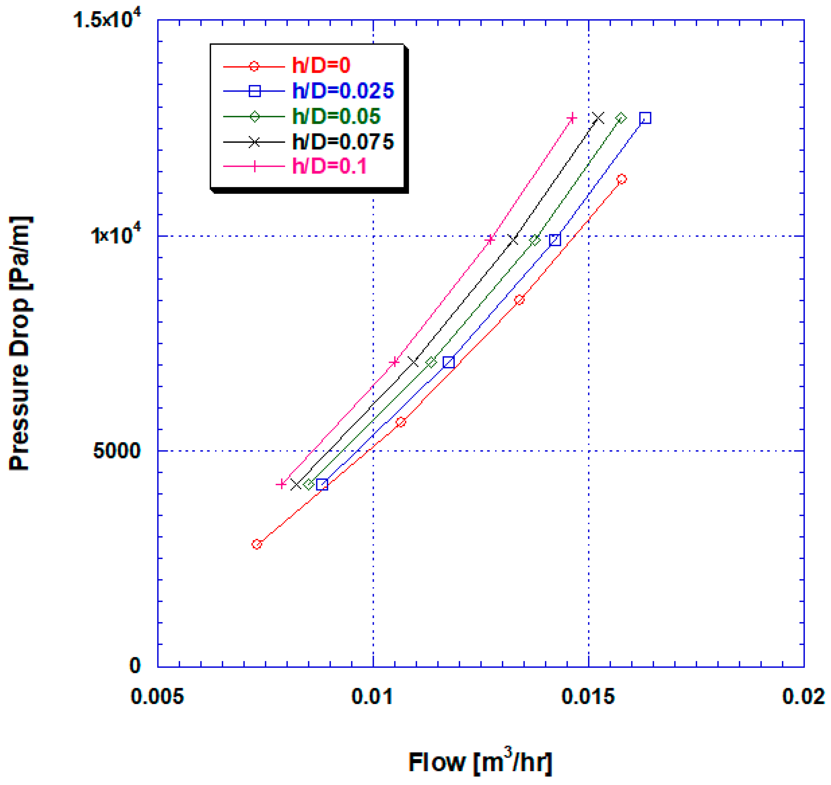
Figure 6.
Friction factor versus Reynolds number for various thicknesses of fouling layer.
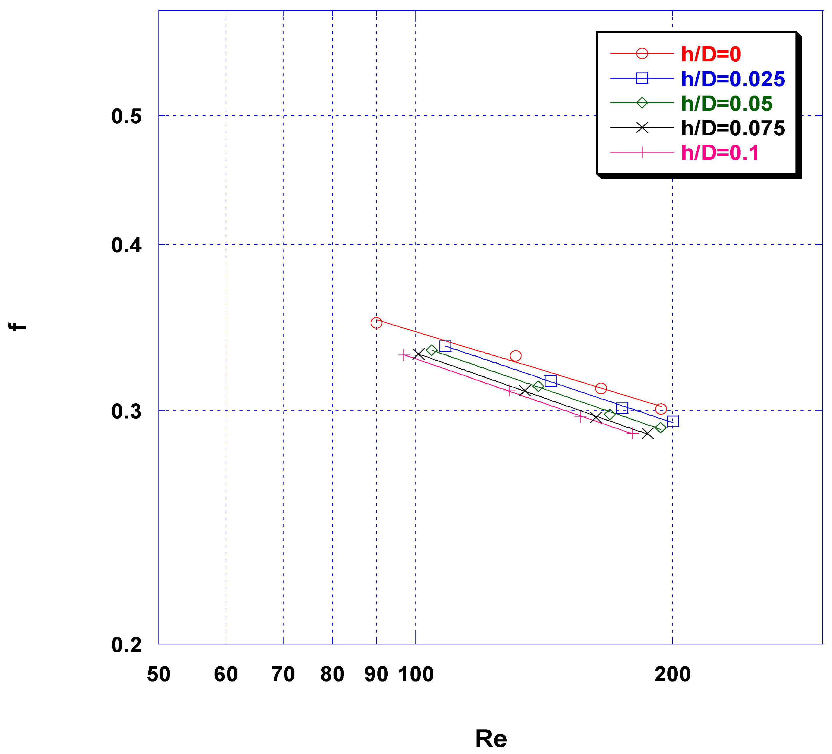
Figure 7.
A view of spatial distribution of the local time-averaged shear stress on the membrane surface for the no-fouling geometry (h/D = 0) compared with distributions for progressively increased fouling-layer thickness; Re ~ 135. In the normalized chromatic scale, the values of 0 and 1 correspond to the minimum and maximum of the plotted variable, respectively.

Figure 8.
Percent probability density function of the dimensionless local time-averaged shear stresses on the membrane surface for the cases examined in this work. Re ~ 135. Shear stresses are normalized with the quantity μU/D.
Figure 8.
Percent probability density function of the dimensionless local time-averaged shear stresses on the membrane surface for the cases examined in this work. Re ~ 135. Shear stresses are normalized with the quantity μU/D.

Figure 9.
Probability density function of the dimensionless local, time-averaged shear stresses on the membrane surface for the four cases of fouling-layer thicknesses examined in this work. Shear stresses are normalized with the quantity μU/D.
Figure 9.
Probability density function of the dimensionless local, time-averaged shear stresses on the membrane surface for the four cases of fouling-layer thicknesses examined in this work. Shear stresses are normalized with the quantity μU/D.


Figure 10.
Probability density function of the time-averaged Sh number at the membrane surface for fouling-layer thickness (h/D) = 0.025 and 0.10 in the Sc number range 1–100.
Figure 10.
Probability density function of the time-averaged Sh number at the membrane surface for fouling-layer thickness (h/D) = 0.025 and 0.10 in the Sc number range 1–100.

Figure 11.
(a) Time and space-average Sh number, on the membrane surface, as a function of ratio D′/D; (b) correlation of dimensionless Sh number parameter (involving Sc and D′/D) as a function of Re number.
Figure 11.
(a) Time and space-average Sh number, on the membrane surface, as a function of ratio D′/D; (b) correlation of dimensionless Sh number parameter (involving Sc and D′/D) as a function of Re number.

Table 1.
Conditions of performed simulations in this study. Spacer geometry: L/D = 8, β = 90°. Sc number range: 1–100.
Table 1.
Conditions of performed simulations in this study. Spacer geometry: L/D = 8, β = 90°. Sc number range: 1–100.
| Case 1 | Case 2 | Case 3 | Case 4 | |
|---|---|---|---|---|
| Fouling-layer thickness, h/D | 0.025 | 0.05 | 0.075 | 0.1 |
| Re number range | 108–200 | 104–193 | 101–187 | 97–180 |
© 2018 by the authors. Licensee MDPI, Basel, Switzerland. This article is an open access article distributed under the terms and conditions of the Creative Commons Attribution (CC BY) license (http://creativecommons.org/licenses/by/4.0/).
Share and Cite
MDPI and ACS Style
Koutsou, C.P.; Karabelas, A.J.; Kostoglou, M. Fluid Dynamics and Mass Transfer in Spacer-Filled Membrane Channels: Effect of Uniform Channel-Gap Reduction Due to Fouling. Fluids 2018, 3, 12. https://doi.org/10.3390/fluids3010012
AMA Style
Koutsou CP, Karabelas AJ, Kostoglou M. Fluid Dynamics and Mass Transfer in Spacer-Filled Membrane Channels: Effect of Uniform Channel-Gap Reduction Due to Fouling. Fluids. 2018; 3(1):12. https://doi.org/10.3390/fluids3010012
Chicago/Turabian StyleKoutsou, Chrysafenia P., Anastasios J. Karabelas, and Margaritis Kostoglou. 2018. "Fluid Dynamics and Mass Transfer in Spacer-Filled Membrane Channels: Effect of Uniform Channel-Gap Reduction Due to Fouling" Fluids 3, no. 1: 12. https://doi.org/10.3390/fluids3010012