Electrode Surface Composition of Dual-Intercalation, All-Graphite Batteries


1
Department of Materials Science and Engineering and the A.J. Drexel Nanomaterials Institute, Drexel University, Philadelphia, PA 19104, USA
2
Sensors and Electron Devices Directorate, U.S. Army Research Laboratory, Adelphi, MD 20783, USA
3
Thin Film Physics Division, Department of Physics, Chemistry and Biology (IFM), Linköping University, SE-583 31 Linköping, Sweden
*
Authors to whom correspondence should be addressed.
C 2017, 3(1), 5; https://doi.org/10.3390/c3010005
Submission received: 19 December 2016
/
Accepted: 31 January 2017
/
Published: 9 February 2017
Abstract
:Dual-intercalation batteries implement graphite electrodes as both cathodes and anodes and offer high specific energy, inexpensive and environmentally sustainable materials, and high operating voltages. Our research investigated the influence of surface composition on capacities and cycling efficiencies of chemically functionalized all-graphite battery electrodes. We subjected core-shell spherical particles and synthetic graphite flakes to high-temperature air oxidation, and hydrogenation to introduce, respectively, –OH, and –H surface functional groups. We identified noticeable influences of electrode surface chemistry on first-cycle efficiencies and charge storage densities of anion and cation intercalation into graphite electrodes. We matched oxidized cathodes and hydrogenated anodes in dual-ion batteries and improved their overall performance. Our approach provides novel fundamental insight into the anion intercalation process and suggests inexpensive and environmentally sustainable methods to improve performance of these grid-scale energy storage systems.

1. Introduction
Electrical energy storage modules offer a solution to the critical problem of inefficient microgrid systems in remote locations, such as the U.S Army’s Forward Operating Bases (FOBs). These currently rely on diesel-powered generators for primary and backup energy supply and are often underrun (i.e., operate at 40%–50% of their peak output capabilities) to accommodate power consumption fluctuations. This operating mode significantly reduces their efficiencies and drives up diesel consumption [1].
Lithium-ion batteries (LIBs) offer sufficiently high energy densities to act as energy management systems in microgrid power applications [2]. Typical batteries implement a graphite anode and a metal oxide cathode (such as LiCoO2), along with an electrolyte composed of lithium salts (typically [Li+][PF6−], [Li+][TFSI−], or [Li+][BF4−]) dissolved in carbonate solvents [3]. Single cells typically operate at 3.6 V and can store 700 to 2400 mAh per cell. The LiCoO2 cathode has a theoretical gravimetric capacity of 274 mAh/g (140 mAh/g practical), while the anode is capable of storing up to 372 mAh/g (300–320 mAh/g practical) [2]. Nevertheless, existing LIBs feature many drawbacks that preclude their implementation in grid-level storage. High-voltage output is limited by the electrochemical stability of electrolytes and requires an inefficient series connection of multiple modules [4]. Oxidized cathodes facilitate gas evolution during electrolyte breakdown, pose swelling/bursting risks, and increase flammability hazards [5,6]. The cathode intercalation compound, LixCoO2 (x <0.5), contributes an additional Co4+ oxidizer hazard. Despite recent improvements of operating efficiencies, charge storage decays with cycling and offers a limited operating life. In addition to including rare, expensive transition metals such as cobalt, expended LIBs cannot be safely disposed of or incinerated without generating toxic byproducts [7].
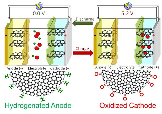
A promising alternative LIB approach depends on a dual-intercalation mechanism that relies on both cations and anions [8,9]. It allows inexpensive and environmentally safe graphite to act as both the cathode and anode. While [Li+] anode intercalation still yields LiC6, [PF6−], cathode intercalation produces (PF6)Cx (x ≥20) [10]. This process, which occurs at 4.5–5.2 V, has a theoretical intercalation capacity of 90–120 mAh/g [11,12]. A mixture of monofluoroethylene carbonate (FEC) and ethylmethyl carbonate (EMC), along with a tris(hexafluoro-iso-propyl)phosphate (HFIP) sacrificial additive [11], acts as an electrochemically stable electrolyte solvent. This approach allows the use of less volatile solvents and inexpensive, easy-to-dispose electrodes, and offers energy densities that are suitable for grid-level implementation. Furthermore, the dual-intercalation process has broad implementation across a wide range of materials, including layered carbides [13], polymer composites [14], graphene [15], and aluminum [16].
Despite important advantages in the dual-intercalation charge storage mechanism, existing all-graphite battery configurations do not yet yield sufficiently high cycling efficiencies and steady-state discharge capacities. Furthermore, although extensive studies of solid/electrolyte (SEI) formation and stability on graphite anodes, as well as reactions involving LiCoO2 cathodes, have been completed, SEI formation on graphite cathodes due to anion intercalation has not been examined. Since the intercalation process strongly depends on processes at the electrode–electrolyte interface [17], heterogeneity and composition differences on electrode surfaces are expected to significantly influence capacity and cycling efficiencies. Certain functional groups can be introduced onto carbon surfaces via high-temperature treatments, air oxidation, plasma and gas treatment, and wet chemistry reactions [18,19]. Subsequently, research efforts must classify surface chemical species as beneficial or detrimental to anion intercalation, determine optimal combinations of cathode and anode surface treatments, and implement them in the graphite cathode fabrication processes.
Our efforts determined the influence of hydrogen and oxygen surface functionalities on the electrochemical performance of graphite cathodes and anodes in dual-ion cycling configurations. Since surface modification efforts have different effects on the graphite basal planes and sheet edges, we relied on both spherical (core-shell MCMB (MesoCarbon MicroBeads) cathodes and CGP (ConocoPhillips Graphite Particles) anodes) and flake-like SFG (Synthetic Flakes of Graphite) materials; all particle morphologies had been previously implemented in dual-intercalation LIBs [11,12]. We relied on conventional and industrially scalable furnace (flowing air at 570 °C or H2 gas at 800 °C to, respectively, oxidize or hydrogenate surfaces) methods and combined characterization of surface compositions with resulting electrochemical performance.
We decoupled the surface chemistry effects for cation and anion intercalation and matched optimal surface treatments of positive and negative electrodes in asymmetric configurations to extract the highest capacities and most stable cycling behaviors.
2. Results and Discussion
2.1. Material Properties
Most of the chemical treatments lightly modified the surface compositions of the materials without significantly transforming their structures. Table 1 summarizes the changes in the specific surface area (SSA) of the various graphite particles as a result of surface modifications. As shown in Figure S1 in the Supporting Information (SI), N2 adsorption/desorption demonstrated well-pronounced Type IV isotherm behavior. These profiles suggested interparticle slits between non-porous particles. Surface modification yielded very small SSA increases—between 0.50 m2·g−1 and 4.78 m2·g−1—and suggested that the chemical treatments did not restructure the well-ordered non-porous carbon particles.
Negligible SSA changes suggested the chemical modification approaches neither activated the particles nor etched micropores into the materials [20]. Pore size distributions (Figure S2 in the SI) showed that chemical treatments retained the pore-free surface morphologies of all three graphite electrode materials. Most observed changes simply removed carbon atoms from surface layers during functionalization. Subsequently, functional groups were retained only on external particle surfaces. Most importantly, their effects on electrochemical cycling were, subsequently, limited solely to intercalation: the SSAs were sufficiently small to safely discount any double layer electrosorption contributions.
Inert TGA analysis (show in Table 1) indicated that the initial carbon materials had negligible amounts of chemical groups on the surface, and all of the chemical treatments increased surface functionality concentrations. The greatest increases were observed for oxidized SFG (11.9 wt %). Overall, as compared to core-shell particles, the stacked SFG flakes exhibited greater concentrations of surface functional groups. Their intrinsic structure, which featured more prevalent exposed edge planes (previously shown to be more unstable) [21], make it more susceptible to functionalization.
XPS analysis, which is summarized in Table 2, provided more information on the specific functionalization of hydrogenated and oxidized MCMB and SFG surfaces. The measurements showed that, although hydrogenation had left some of the oxygen-containing groups on the surfaces, most of them converted to hydrogen-rich groups and desorbed oxygen species following the treatment steps. Peak deconvolution (shown in Table S1 in SI) showed that most predominant oxidized sample groups were C–O, which suggested hydroxyl and acid surface functionalities in those samples. Peak deconvolution of the hydrogenated MCMB material showed that its surface structure was predominantly composed of C–H (50.1 at %), C–C (45 at %), and C–O (5.0 at %). Therefore, we were able to conclude that the tested graphite electrode materials exhibited desired, and sufficiently distinct, surface chemistries.
2.2. Anion Intercalation
Differently functionalized graphite materials acted as cathodes in half-cells and were cycled at a C/10 rate (assuming a 90 mAh·g−1 maximum [PF6−] intercalation capacity). The resulting anion intercalation/deintercalation profiles, as well as cycle-dependent capacities, are shown in Figure 1. The MCMB anion intercalation profiles (Figure 1a shows the first full charge-discharge profile) suggest onset of [PF6−] insertion and staging in oxidized graphite at lower voltages than other functionalized surfaces. Although the first-cycle capacity of oxidized core-shell electrodes is lower than the untreated graphite (discharge value from 5th cycle in Figure 1b), it maintains higher long-term efficiency and exhibits improved capacity (92.4 mAh·g−1) compared to the pristine material (73.1 mAh·g−1).
Hydrogenated MCMB cathodes demonstrated noticeably different charge/discharge behaviors. Although they demonstrated higher first-cycle charge storage capacities, their performance decayed very rapidly, and their efficiencies dropped below 60%.
Differently functionalized SFG cathodes demonstrated well-defined anion intercalation staging behavior (Figure 1c). Although efficiencies of first full charge–discharge cycles of the untreated cathodes (Table 3) exceeded those of either of the functionalized counterparts, steady-state capacity and efficiencies of oxidized and hydrogenated synthetic graphite electrodes was higher after the 2nd full charge/discharge cycle. All SFG electrodes demonstrated higher efficiencies than their MCMB counterparts and, especially, demonstrated higher capacities near the 5.0–5.2 V vertex potentials. Discharge capacities for most functionalized SFG cathodes exhibited constant decays after the 1st cycle.
Table 3 summarizes the first cycle efficiencies, steady-state capacities, cathode polarization potentials, and comparatively functionalized CGP anode ([Li+] intercalation) performance. For both MCMB and SFG cathodes, hydrogenation consistently reduced 1st cycle efficiencies, and oxidation slightly increased them from 74% to 88% (in MCMB) and from 79% to 88% (in SFG). Although none of the treatments improved first-cycle efficiencies of the CGP anode, hydrogenated surfaces yielded higher steady-state efficiencies than oxidized ones. The lithiation/delithiation of functionalized anodes is shown in Figure S3 in SI. This finding was in direct contrast to anion intercalation at the cathodes, and the results underscored the significant differences between cation and anion intercalation fundamentals and resulting SEI formation. It should be noted that oxidation of all three graphite materials noticeably improved their capacities for, at minimum, the first few cycles. For applications such as primary batteries, which do not require long-duration cyclability, these approaches may improve device energy densities without sacrificing reliability or cost advantages.
2.3. Long-Term Cyclability
A separate set of electrode materials for MCMB and SFG functionalized graphite cathodes were cycled in half-cell configurations at a C/2 rate. The discharge capacities and coulombic efficiencies are shown in Figure 2. These cells did not undergo any pre-cycling or pre-conditioning and operated squarely in the 4.0–5.1 V regime.
For the MCMB core-shell cathodes, the untreated and oxidized electrodes retained stable performance through 200 cycles. Although the oxidized materials had slightly lower discharge capacities during the later cycles, the charge storage densities of the oxidized graphite materials were the highest of all tested configurations until the 75th cycle.
The SFG untreated cathode cells failed at approximately the 75th cycle. The oxidized synthetic graphite cells avoided failure over 200 cycles, but their performance decreased to 26% of its initial capacity. Hydrogenated cathodes performed poorly in both SFG and MCMB cells, and failed (or degraded beyond any measurable operating levels) after 30 cycles. Although the exact cause of this breakdown remains to be determined, the positively charged hydrogenated surfaces were more likely to engage in irreversible electron transfer reactions with organic solvents at high positive potentials.
X-Ray Diffraction analyzed the long-range stacking order (along the c-axis direction) of the cathode materials before and after cycling. The experiments aimed to determine whether the electrodes underwent any loss of crystallinity—a common problem in layered electrode materials—due to anion intercalation. The results are summarized in Figure 3. Core-shell MCMB cathodes (Figure 3a) did not exhibit significant destruction of the graphite lattice. Electrochemical impedance spectroscopy (EIS) analyzed the equivalent series resistance (ESR) of the half-cells before and after cycling. The Nyquist plot for hydrogenated MCMB material before and after cycling (Figure 3b) showed that extended charging/discharging resulted in a prominent semi-circular regime in the mid-frequency range. This behavior may be attributed to charge transfer resistance increases and may suggest a buildup of electrolyte decomposition products on cathode surfaces. It is, however, possible that anion intercalation exfoliated graphite electrodes, caused them to lose contact from the Al current collectors, and degraded the batteries. Stacking and long-range order along the [002] direction substantially decreased for most of the cycled SFG electrodes. It should be noted, however, that most of the synthetic flake electrodes that had been analyzed using X-Ray Diffraction were partially charged. This influenced the intensities of the [002] graphite peaks and added intercalated [PF6]x[C]y phases to resulting diffractograms. Comparative EIS-derived charge transfer resistance changes, which are shown in Table S2 in SI, demonstrated increased resistance of most cells after extended cycling. Voltage-induced irreversible breakdown of the organic solvents, layers of LiPF6 out of solution, corroded current collectors, and exfoliated (damaged) cathodes all possibly contributed to this effect. The exact causes require further investigation and will be discussed in future work.
2.4. Dual-Ion Intercalation Configuration
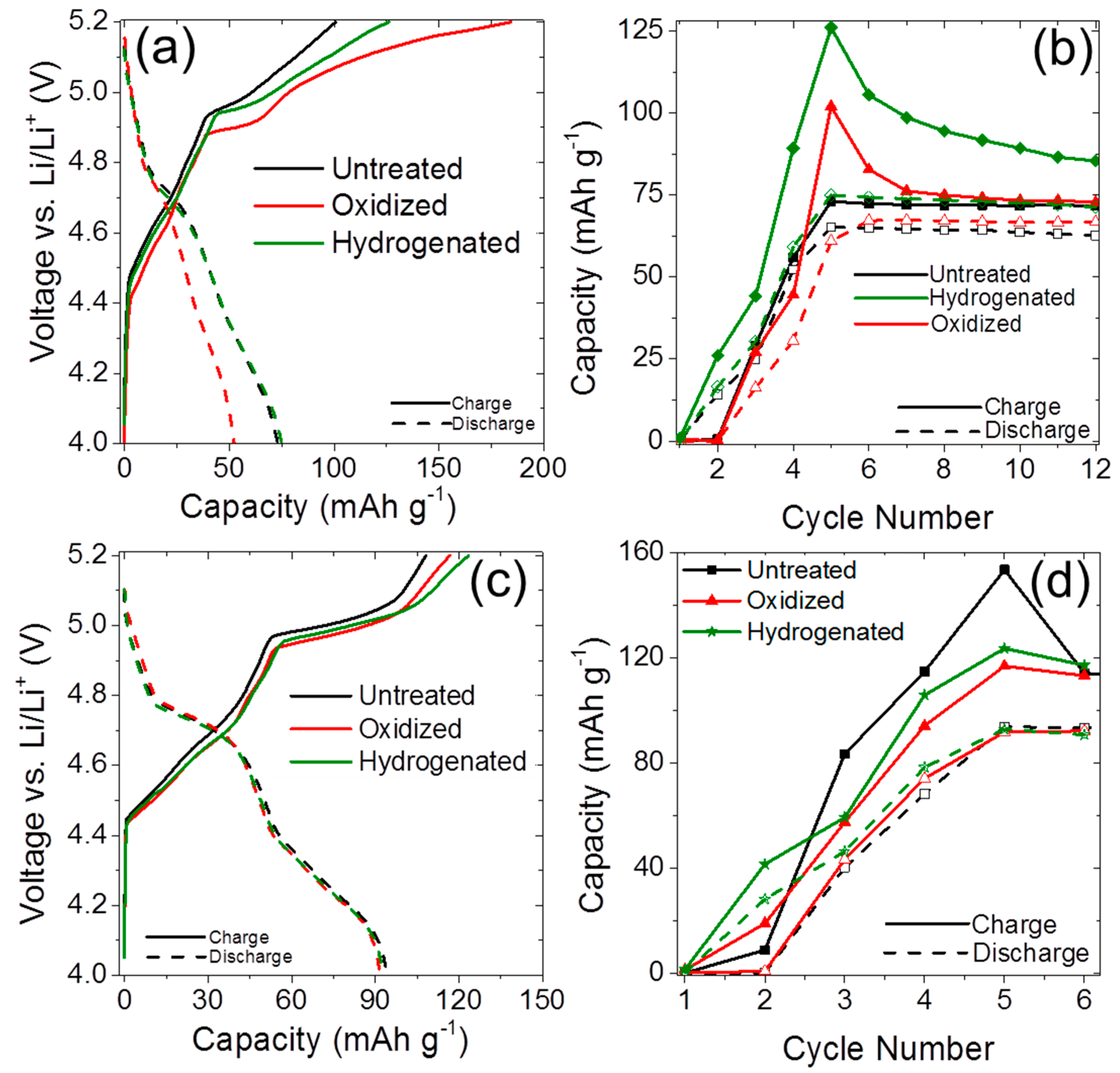
Four different cells with tailored anode and cathode surface chemistries compared the influences of electrode interfaces and highlighted the impacts of surface functional groups on dual intercalation processes. One cell used oxidized MCMB cathode and hydrogenated CGP anode, and another cell used oxidized SFG cathode and hydrogenated CGP anode. Two baseline tests used untreated CGP anode with untreated MCMB or SFG cathodes. To balance the relative predicted intercalation charge densities (90 mAh·g−1 for cathode and 320 mAh·g−1 for anode), the cathode masses exceeded the anode masses by factors of three. Results of C/10 cycling are shown in Figure 4.
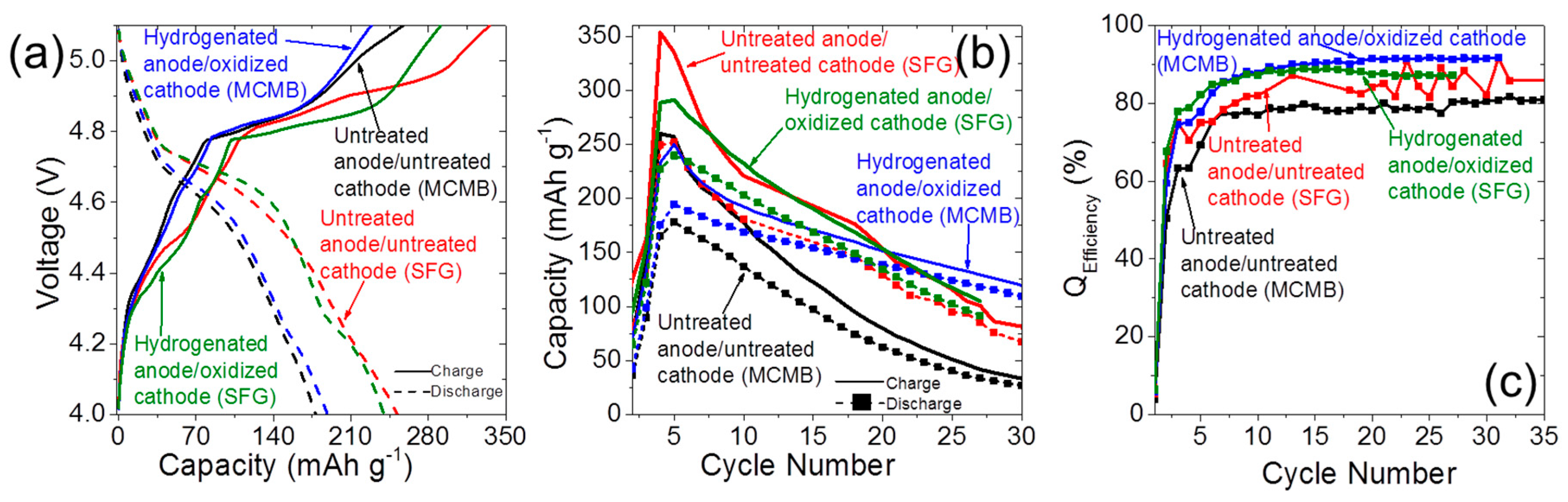
The functionalized cells performed at higher coulombic efficiencies and offered higher charge capacities than their untreated counterparts. The voltage vs. capacity profiles demonstrated characteristic inflection points, which corresponded with distinct [PF6−] intercalation stages [12] for the asymmetrically functionalized cells and a higher polarization voltage. Additionally, both first-cycle and subsequent coulombic efficiencies for the hydrogenated anode–oxidized cathode cells showed improvements over bare carbon surfaces. Although SFG-based cells demonstrated similar capacitive decay for untreated and oxidized cathodes, oxidized core-shell MCMB cathodes showed substantially improved stability as compared to their untreated counterparts.
In the case of both the core-shell MCMB and flake SFG electrodes, oxidized cathodes and hydrogenated anodes provided more stable cycling and higher coulombic efficiencies than their untreated counterparts. The observed stability improvements of oxidized cathodes agree with previously reported results for carbon black LIB materials [22]. The most conventional explanation of this effect suggests that the high concentration of negatively charged oxygen groups (–C=O, –HCOO, –C–O–C, –OH, etc.), due to electron counting, precludes oxidation of organic solvents at the cathode under high applied voltages. Furthermore, oxidized carbons at cathode surfaces likely formed sp3 configurations, which, unlike sp2 carbons, had not degraded as rapidly during [PF6−] intercalation above 4.1 V [23]. The required asymmetry in surface composition demonstrates the distinct differences between anion and cation intercalation processes. Although lithiation and [PF6−] insertion used FEC and EMC solvents, and relied on the HFIP additive for SEI stability, they benefitted most from, respectively, hydrogenated anodes and oxidized cathodes. Surface modification processes introduced chemical species onto electrode surfaces that minimized electrolyte oxidation and reduction at, respectively, cathodes and anodes. Subsequently, fewer irreversible solvent breakdown reactions and [Li+][PF6−] desolvation (salt deposition) processes occurred at each electrolyte. This suggests that other surface functionalities, such as halogenation and amination, may further improve cycling efficiency and stability of dual-intercalation graphite electrodes in the future.
3. Materials and Methods
All graphite materials were used as received. The first cathode material was a core-shell graphitized particle (hard carbon surface coating surrounded well-ordered graphite) MCMB 10-28 (Osaka Gas, Japan). The second cathode material was a synthetic graphite flake material SFG-44. The anode material was a proprietary core-shell CGP-A12 ellipsoid particle (ConocoPhillips, USA). They are shown in Figure S4 in SI and are, respectively, labeled as “MCMB,” “SFG,” and “CGP” in the text.
To oxidize the materials, carbon powders were placed in alumina boats, heated in alumina tube furnaces (open to air) to 570 °C, and held at that temperature for 4 h. To hydrogenate graphite, we took oxidized graphite particles, placed them into quartz tube furnaces (under flowing Ar gas), and heated them at 800 °C under flowing H2 gas (at 0.5 L·min−1) for 8 h [24].
Micromeretics Tristar II porosimeter used N2 adsorption to quantify the specific surface area (SSA) of the functionalized materials. Samples were outgassed at 105 C for 24 h, and N2 sorption was carried out in the 0.05–0.995 P·P0−1 range using a liquid nitrogen bath (−193 °C). Brunauer-Emmett-Teller (BET) SSA was calculated in the 0.05–0.30 P·P0−1 range [25] using Tristar II 3020 V1.03 Software (Micromeretics Instrument Corporation, Norcross, GA, USA).
X-Ray Photoelectron Spectroscopy (XPS) identified the surface chemistry and provided elemental analysis and functional group content of the graphite materials. Physical Electronic VersaProbe 5000 (VersaProbe, Chanhassen, MN, USA), with a 100 µm monochromatic Al-Kα X-ray beam Kratos AXIS surface analysis system (Ultra DLD), was used for performing the XPS measurements. CasaXPS Version 2.3.16 RP 1.6 software (Casa Software Ltd, Teignmouth, UK) deconvoluted the functional group peaks. Additionally, thermogravimetric analysis (TGA) with a TGA7 Perkin-Elmer instrument (Perkin-Elmer Corporation, Waltham, MA, USA) quantified total functional groups on each material. Samples were placed in Pt crucibles, heated to 750 °C at 5 °C·min−1 in a N2 environment, and held at that temperature for 1 h. Prior to temperature ramp-up, samples were held at 110 °C for 2 h in an inert atmosphere to desorb water or other chemical species. PYRIS Software (Perkin-Elmer) analyzed results.
Carbon structure of materials was evaluated using a Rigaku Ultima III X-Ray Diffractometer (XRD). This method evaluated both initial and electrochemically cycled materials. The instrument used 20 kV accelerating voltage in Bragg-Brentano mode. Materials were analyzed in the 5–50° 2θ range at a 2° 2θ min−1 scan rate. MDI Jade 7 Software (Materials Data, Inc., Livermore, CA, USA) applied baseline corrections and conducted peak fitting.
An amount of 2.0 M [Li+][PF6−] in monofluoroethylene carbonate (FEC)/ethylmethyl carbonate (EMC) 1:1(v/v) mixture, along with a tris(hexafluoro-iso-propyl)phosphate (HFIP) additive, acted as the electrolyte for all cells (schematics of all electrolyte components shown in Figure S5 in SI). Graphite powders were mixed with poly(vinylidene) fluoride (PVDF) binder and conductive carbon black in n-methyl-2-pyrrolidone (NMP) solvent in an 80:10:10 ratio for electrode assembly. Cathode slurries were applied on a thin coating onto carbon-coated aluminum current collectors using a 30 μm doctor blade; anode materials were applied onto copper foil using a 10 µm doctor blade. The resulting mass loading of electrodes was 3.5 mg·cm−2. Hoshen 2035 coin cells (1.59 cm diameter) were used to test both half-cell and full-cell configurations. Half-cells used Li metal counter electrode disks. Two layers of Celgard 2400 separator, along with a sheet of non-woven polypropylene fiber mat were used as separators. Cathode test cans were aluminum clad/Ni plated/stainless steel with a Pt tab ultrasonically welded inside the can to make direct contact with the coated electrode, while anode cans were composed of 316 stainless steel (assembly shown in Figure S6 in SI). Cathode: anode electrodes maintained a 3:1 mass ratio in full dual-intercalation cells.
Electrochemical performance was measured using a MACCOR Series 4000 battery tester (MACCOR Corporation, Tulsa, OK, USA). Cathode half-cells were charged/discharged using a C/10 rate (assuming a theoretical 90 mAh/g intercalation capacity, based on active material mass) using galvanostatic cycling. Starting at Open Circuit Potential (OCP), cells were preconditioned using single cycles in the 4.0–4.2 V, 4.0–4.6 V, 4.0–4.8 V, and 4.0–5.0 V range (vs. Li/Li+). Subsequently, cells were cycled between 4.0 and 5.2 V up to 200 cycles. Separately, cells were cycled at a C/2 rate with no preconditioning. Anode cells were cycled at C/10 rate (based on a 300 mAh/g expected intercalation capacity) between 0.5 V and 35 mV vs. Li/Li+. Dual intercalation cells were tested using the same pre-conditioning procedures as cathode half cells, with a vertex potential of 5.1 V. Polarization potentials were calculated from the inflection point in the voltage vs. capacitance relationship of the 1st full voltage range cycle.
Electrochemical Impedance Spectroscopy (EIS) measured the charge transfer resistance between electrodes and current collectors of coin cells before and after cycling with a Solartron SI 1287 potentiostat. Voltage oscillated with ±10 mV amplitude (vs. OCP) at a dampening frequency (106–10−2 Hz). Charge transfer resistance (RT) was calculated by the Re (Z) size of the semi-circular region at mid-range oscillation frequencies [26].
4. Conclusions
We were able to evaluate the influence of hydrogen- and oxygen-containing surface functional groups on efficiency and charge storage densities of graphite cathodes and anodes in dual-intercalation batteries. Particles with flake morphologies featured more exposed edge sites and were more susceptible to chemical treatments. While oxygen functional groups improved cyclability of cathodes, hydrogen functional groups were most beneficial for anode materials. Conversely, hydrogenated cathodes and oxidized anodes were most detrimental to electrochemical performance. Therefore, influence of specific functional groups strongly depended on the applied potential and matched with specific intercalated ions. When hydrogenated anodes were coupled with oxidized cathodes in all-graphite dual-intercalation cells, the resulting batteries demonstrated higher capacities, cyclabilities, and coulombic efficiencies than their untreated counterparts.
We relied on environmentally benign and economically affordable surface treatments to improve the performance of these all-graphite batteries and, subsequently, confirmed their status as a cost-effective solution for microgrid energy storage. We provided additional fundamental insight into the dual-intercalation process, and, in particular, the effects of anion insertion into graphite. Multiple other surface treatments, such as amination and moderate fluorination, remain promising pathways to even greater efficiencies and long-term stable cyclabilities; they must be explored in subsequent efforts. Finally, while surface chemistry-dependent differences suggested SEI formation on cathodes during anion intercalation, the structure, composition, and the mechanism of formation of this layer on positively charged electrodes remains unclear. Ongoing investigation into these processes will have broad implications for dual-intercalation batteries and apply to both graphite electrodes and other emerging materials, such as layered aluminum, transition metal carbide carbides, and boron nitrides.
Supplementary Materials
Supplementary materials can be found at https://www.mdpi.com/2311-5629/3/1/5/s1.
Acknowledgments
This research was funded by the U.S. Army Research Laboratory. Boris Dyatkin’s research at ARL was funded by the College Qualified Leaders (CQL) Army Educational Outreach Program, which is administered by the American Society for Engineering Education (ASEE). All synthesis, materials characterization, and electrochemical testing experiments were completed at the Adelphi Laboratory Center (ALC) of the U.S. Army Research Laboratory and at Drexel University. The authors acknowledge Jeffrey Wolfenstine (ARL) for assistance with XRD measurements. The authors thank Oleg Borodin (ARL) and Yury Gogotsi (Drexel University) for helpful discussions.
Author Contributions
Boris Dyatkin and Jeffrey A. Read conceived and designed the experiments; Boris Dyatkin performed the materials synthesis, characterization, and electrochemical testing experiments; Boris Dyatkin and Jeffrey A. Read analyzed the data; Joseph Halim contributed XPS measurements and analyzed resulting data; Boris Dyatkin, Joseph Halim, and Jeffrey A. Read wrote the paper.
Conflicts of Interest
The authors declare no conflict of interest.
References
- Kelly, R.L.; Oriti, G.; Julian, A.L. Reducing fuel consumption in a forward operating base using an energy management system. In Proceedings of the IEEE 2013 Energy Conversion Congress and Exposition, Denver, CO, USA, 15–19 September 2013; pp. 1330–1336.
- Reddy, M.V.; Subba Rao, G.V.; Chowdari, B.V.R. Metal oxides and oxysalts as anode materials for Li ion batteries. Chem. Rev. 2013, 113, 5364–5457. [Google Scholar] [CrossRef] [PubMed]
- Schmuelling, G.; Placke, T.; Kloepsch, R.; Fromm, O.; Meyer, H.-W.; Passerini, S.; Winter, M. X-ray diffraction studies of the electrochemical intercalation of bis(trifluoromethanesulfonyl)imide anions into graphite for dual-ion cells. J. Power Sour. 2013, 239, 563–571. [Google Scholar] [CrossRef]
- Borodin, O.; Behl, W.; Jow, T.R. Oxidative stability and initial decomposition reactions of carbonate, sulfone, and alkyl phosphate-based electrolytes. J. Phys. Chem. C 2013, 117, 8661–8682. [Google Scholar] [CrossRef]
- Simon, P.; Gogotsi, Y.; Dunn, B. Where do batteries end and supercapacitors begin? Science 2014, 343, 1210–1211. [Google Scholar] [CrossRef] [PubMed] [Green Version]
- Simon, P.; Gogotsi, Y. Capacitive energy storage in nanostructured carbon–electrolyte systems. Acc. Chem. Res. 2013, 46, 1094–1103. [Google Scholar] [CrossRef] [PubMed]
- Dyatkin, B.; Presser, V.; Heon, M.; Lukatskaya, M.R.; Beidaghi, M.; Gogotsi, Y. Development of a green supercapacitor composed entirely of environmentally friendly materials. ChemSusChem 2013, 6, 2269–2280. [Google Scholar] [CrossRef] [PubMed]
- Dahn, J.R.; Seel, J.A. Energy and capacity projections for practical dual-graphite cells. J. Electrochem. Soc. 2000, 147, 899–901. [Google Scholar] [CrossRef]
- Santhanam, R.; Noel, M. Electrochemical intercalation of ionic species of tetrabutylammonium perchlorate on graphite electrodes. A potential dual-intercalation battery system. J. Power Sour. 1995, 56, 101–105. [Google Scholar] [CrossRef]
- Tasaki, K. Density functional theory study on structural and energetic characteristics of graphite intercalation compounds. J. Phys. Chem. C 2013, 118, 1443–1450. [Google Scholar] [CrossRef]
- Read, J.A.; Cresce, A.V.; Ervin, M.H.; Xu, K. Dual-graphite chemistry enabled by a high voltage electrolyte. Energy Environ. Sci. 2014, 7, 617–620. [Google Scholar] [CrossRef]
- Read, J.A. In-situ studies on the electrochemical intercalation of hexafluorophosphate anion in graphite with selective cointercalation of solvent. J. Phys. Chem. C 2015, 119, 8438–8446. [Google Scholar] [CrossRef]
- Er, D.; Li, J.; Naguib, M.; Gogotsi, Y.; Shenoy, V.B. Ti3C2 mxene as a high capacity electrode material for metal (Li, Na, K, Ca) ion batteries. ACS Appl. Mater. Interfaces 2014, 6, 11173–11179. [Google Scholar] [CrossRef] [PubMed]
- Panero, S.; Spila, E.; Scrosati, B. A new type of a rocking-chair battery family based on a graphite anode and a polymer cathode. J. Electrochem. Soc. 1996, 143, L29–L30. [Google Scholar] [CrossRef]
- Kim, H.; Park, K.-Y.; Hong, J.; Kang, K. All-graphene-battery: Bridging the gap between supercapacitors and lithium ion batteries. Sci. Rep. 2014, 4. [Google Scholar] [CrossRef] [PubMed]
- Zhang, X.; Tang, Y.; Zhang, F.; Lee, C.-S. A novel aluminum–graphite dual-ion battery. Adv. Energy Mater. 2016. [Google Scholar] [CrossRef]
- Tasaki, K. Solvent decompositions and physical properties of decomposition compounds in Li-ion battery electrolytes studied by DFT calculations and molecular dynamics simulations. J. Phys. Chem. B 2005, 109, 2920–2933. [Google Scholar] [CrossRef] [PubMed]
- Dyatkin, B.; Zhang, Y.; Mamontov, E.; Kolesnikov, A.I.; Cheng, Y.; Meyer, H.M.; Cummings, P.T.; Gogotsi, Y. Influence of surface oxidation on ion dynamics and capacitance in porous and non-porous carbon electrodes. J. Phys. Chem. C 2016, 120, 8730–8741. [Google Scholar] [CrossRef]
- Dyatkin, B.; Mamontov, E.; Cook, K.C.; Gogotsi, Y. Capacitance, charge dynamics, and electrolyte-surface interactions in functionalized carbide-derived carbon electrodes. Prog. Nat. Sci. Mater. Int. 2015, 25, 631–641. [Google Scholar] [CrossRef]
- Osswald, S.; Portet, C.; Gogotsi, Y.; Laudisio, G.; Singer, J.P.; Fischer, J.E.; Sokolov, V.V.; Kukushkina, J.A.; Kravchik, A.E. Porosity control in nanoporous carbide-derived carbon by oxidation in air and carbon dioxide. J. Solid State Chem. 2009, 182, 1733–1741. [Google Scholar] [CrossRef]
- Punckt, C.; Muckel, F.; Wolff, S.; Aksay, I.A.; Chavarin, C.A.; Bacher, G.; Mertin, W. The effect of degree of reduction on the electrical properties of functionalized graphene sheets. Appl. Phys. Lett. 2013, 102, 023114. [Google Scholar] [CrossRef]
- Kostecki, R.; Richardson, T.; Boesenberg, U.; Pollak, E.; Lux, S. Modified carbon black materials for lithium-ion batteries. U.S. Patent US9368798 B2, 14 June 2016. [Google Scholar]
- Isono, Y.; Yoshida, A.; Hishiyama, Y.; Kaburagi, Y. Carbonization and graphitization of shavings filed away from kapton. Carbon 2004, 42, 1799–1805. [Google Scholar] [CrossRef]
- Mochalin, V.N.; Shenderova, O.; Ho, D.; Gogotsi, Y. The properties and applications of nanodiamonds. Nat. Nano 2012, 7, 11–23. [Google Scholar] [CrossRef] [PubMed]
- Brunauer, S.; Emmett, P.H.; Teller, E. Adsorption of gases in multimolecular layers. J. Am. Chem. Soc. 1938, 60, 309–319. [Google Scholar] [CrossRef]
- Taberna, P.L.; Portet, C.; Simon, P. Electrode surface treatment and electrochemical impedance spectroscopy study on carbon/carbon supercapacitors. Appl. Phys. A 2006, 82, 639–646. [Google Scholar] [CrossRef]
Figure 1.
(a) Capacity vs. Voltage (vs. Li/Li+) of first cycle full-potential C/10 charge and discharge (between 4.0 and 5.2 V)) for differently functionalized MesoCarbon MicroBeads (MCMB) cathodes. (b) Corresponding charge/discharge cycle profiles (including 4 initial pre-conditioning cycles) for MCMB cathodes. Corresponding charge/discharge and capacity plots are shown in (c) and (d) for chemically modified Synthetic Flakes of Graphite (SFG) cathodes.

Figure 2.
C/2 discharge capacity performance for (a) MCMB and (b) SFG cathode half-cells. Cells were tested until discernible failure or 200 cycles.
Figure 2.
C/2 discharge capacity performance for (a) MCMB and (b) SFG cathode half-cells. Cells were tested until discernible failure or 200 cycles.
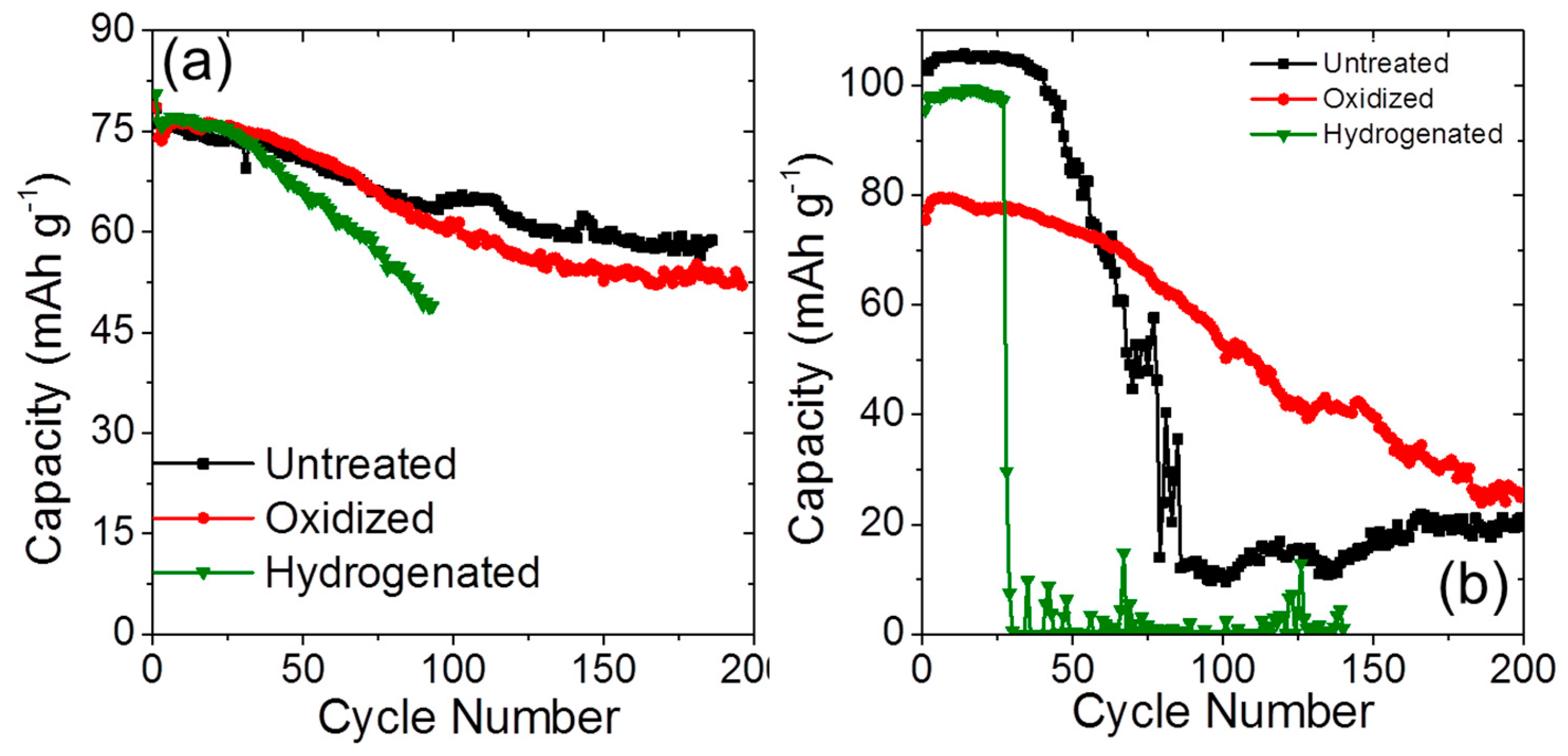
Figure 3.
(a) X-Ray Diffraction (XRD) analysis of long-range graphitic ordering in the [002] direction of the initial MCMB cathode and different surface treated materials after C/2 cycling; (b) Nyquist impedance plot that compares the charge transfer resistance between the hydrogenated MCMB cathode and the current collector before and after cycling; (c) XRD analysis of the SFG cathode before and after cycling. Note that the cycled untreated material retained partial charge (i.e., ions intercalated into its structure), which likely contributed to higher [002] long-range ordering; (d) Nyquist impedance plot that compared the charge transfer resistance of the oxidized SFG cathode before and after cycling.
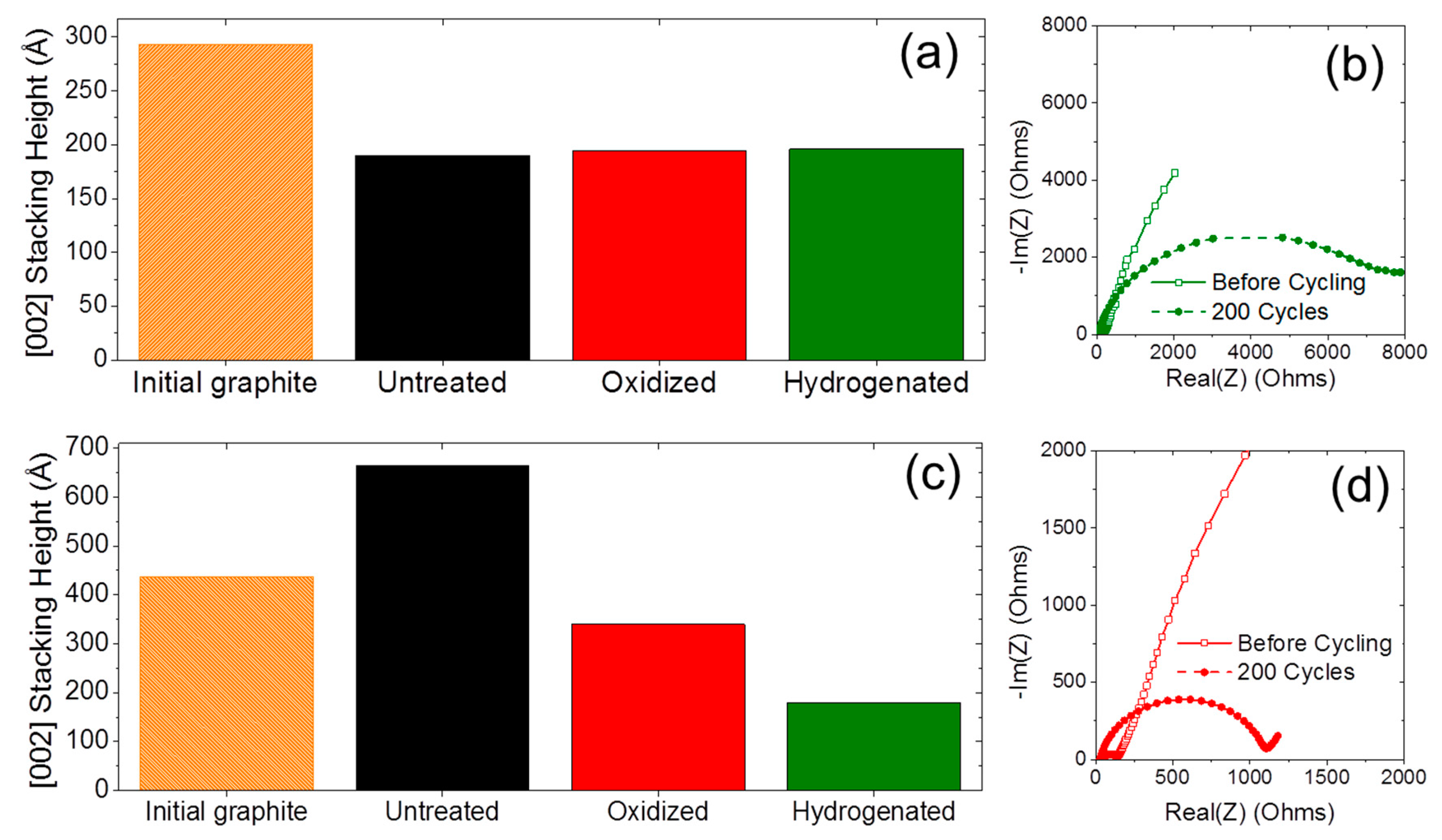
Figure 4.
(a) Voltage vs. capacity of 1st 4.0–5.1 V cycle of full dual-intercalation cells. In each case, a graphite cathode (either MCMB or SFG) is matched with a graphite anode (CGP); (b) Charge/discharge capacity (including pre-conditioning) using C/10 cycles normalized to anode mass; (c) Coulombic efficiencies for first 35 cycles.


Table 1.
Gas sorption-derived specific surface area measurements and functional group content of chemically modified MesoCarbon MicroBeads (MCMB), Synthetic Flakes of Graphite (SFG), and ConocoPhillips Graphite Particles (CGP) graphite electrode particles. Functional group content was derived from thermogravimetric analysis (TGA).
| Surface Chemistry | MCMB | SFG | CGP | |||
|---|---|---|---|---|---|---|
| Specific Surface Area | Functional Group Content | Specific Surface Area | Functional Group Content | Specific Surface Area | Functional Group Content | |
| Untreated | 1.99 m2·g−1 | 0.52 wt % | 1.34 m2·g−1 | 0.95 wt % | 1.48 m2·g−1 | 0.41 wt % |
| Oxidized | 2.49 m2·g−1 | 1.72 wt % | 4.64 m2·g−1 | 11.92 wt % | 6.21 m2·g−1 | 3.54 wt % |
| Hydrogenated | 2.26 m2·g−1 | 0.44 wt % | 2.72 m2·g−1 | 2.05 wt % | 6.26 m2·g−1 | 0.21 wt % |
Table 2.
X-ray photoelectron spectroscopy (XPS)-derived elemental analysis comparison of different functionalized MCMB and SFG graphite cathode materials.
| Element | MCMB | SFG | |
|---|---|---|---|
| Oxidized | Hydrogenated | Oxidized | |
| Carbon (at %) | 98.2 | 99.4 | 98.2 |
| Oxygen (at %) | 1.8 | 0.6 | 1.8 |
Table 3.
First-cycle and steady-state efficiencies, capacities, and polarization potentials of functionalized graphite MCMB and SFG cathodes and ConocoPhillips Graphite Particles (CGP) anodes tested in half-cell configurations.
| Material | Surface Chemistry | Cycle 1 Efficiency | Steady-State Efficiency | Peak Capacity | Polarization Potential |
|---|---|---|---|---|---|
| MCMB Cathode | Untreated | 72.5% | 88.1% | 73.1 mAh·g−1 | 4.94 V |
| Oxidized | 74.1% | 87.7% | 92.4 mAh·g−1 | 4.92 V | |
| Hydrogenated | 59.5% | 81.4% | 75.0 mAh·g−1 | 5.03 V | |
| SFG Cathode | Untreated | 79.1% | 82.0% | 94.2 mAh·g−1 | 5.04 V |
| Oxidized | 78.5% | 88.2% | 94.1 mAh·g−1 | 5.02 V | |
| Hydrogenated | 75.1% | 83.8% | 92.7 mAh·g−1 | 5.02 V | |
| CGP Anode | Untreated | 88.9% | 99.5% | 309.5 mAh·g−1 | |
| Oxidized | 86.4% | 99.1% | 340.5 mAh·g−1 | ||
| Hydrogenated | 87.7% | 99.2% | 268.7 mAh·g−1 |
© 2017 by the authors. Licensee MDPI, Basel, Switzerland. This article is an open access article distributed under the terms and conditions of the Creative Commons Attribution (CC BY) license ( http://creativecommons.org/licenses/by/4.0/).
Share and Cite
MDPI and ACS Style
Dyatkin, B.; Halim, J.; Read, J.A. Electrode Surface Composition of Dual-Intercalation, All-Graphite Batteries. C 2017, 3, 5. https://doi.org/10.3390/c3010005
AMA Style
Dyatkin B, Halim J, Read JA. Electrode Surface Composition of Dual-Intercalation, All-Graphite Batteries. C. 2017; 3(1):5. https://doi.org/10.3390/c3010005
Chicago/Turabian StyleDyatkin, Boris, Joseph Halim, and Jeffrey A. Read. 2017. "Electrode Surface Composition of Dual-Intercalation, All-Graphite Batteries" C 3, no. 1: 5. https://doi.org/10.3390/c3010005
Note that from the first issue of 2016, this journal uses article numbers instead of page numbers. See further details here.