
Mechanical and Electrical Properties of Elastomer Nanocomposites Based on Different Carbon Nanomaterials

196 Boulevard Bineau, 92200 Neuilly-Sur-Seine, France
C 2017, 3(2), 10; https://doi.org/10.3390/c3020010
Submission received: 17 February 2017
/
Revised: 27 March 2017
/
Accepted: 7 April 2017
/
Published: 12 April 2017
Abstract
:Carbon nanostructures including carbon black, carbon nanotubes, graphite or graphene have attracted a tremendous interest as fillers for elastomeric compounds. The preparation methods of nanocomposites that have a strong impact on the state of filler dispersion and thus on the properties of the resulting composites, are briefly described. At a same filler loading, considerable improvement in stiffness is imparted to the host polymeric matrix by the carbon nanomaterials with regard to that provided by the conventional carbon black particles. It is mainly attributed to the high aspect ratio of the nanostructures rather than to strong polymer-filler interactions. The orienting capability of the anisotropic fillers under strain as well the formation of a filler network, have to be taken into account to explain the high level of reinforcements. A comparison of the efficiency of the different carbon nanostructures is carried out through their mechanical and electrical properties but no clear picture can be obtained since the composite properties are strongly affected by the state of filler dispersion.
1. Introduction
Elastomers that consists of polymeric chains with a high degree of flexibility and mobility, exhibit rubber-like elasticity if the chains are joined into a network structure [1]. They can undergo large deformations and they have very good damping characteristics making them well suited in energy dissipation. Rubberlike materials find applications in many sectors ranging from automobile tyres and conveyor belts, hoses, adhesives, aircraft industry, etc. The rubberlike elasticity is observed above the glass transition temperature Tg and above the melting point, Tm for crystalline polymers. Natural rubber undergoes strain-induced crystallization that accounts for the large increase in modulus at high deformation because the crystallites act as additional cross-links in the network. From this point of view, strain-induced crystallization can be considered as an auto-reinforcement of the elastomer. Those elastomers that cannot undergo strain-induced crystallization, are generally compounded with additives consisting of fillers like carbon black or silica in order to increase the modulus, tensile strength and wear resistance of the rubber material [2,3,4,5]. However, high loading levels of conventional fillers (often above 40 phr, “phr” = parts per 100 parts of rubber by weight) are required to achieve the desired properties.
Over the past few years, nanofillers have been extensively used in rubber nanocomposites on account of their small size and the corresponding increase in the surface area allowing significant improvement in the matrix properties at low filler loadings. The state of filler dispersion and orientation in the matrix, their size and aspect ratio as well as the interactions with the polymer chains, have been shown to be crucial parameters that determine the reinforcing ability of these nanoparticles.
Isodimensional nanofillers (SiO2 or TiO2) are spherical particles that can be generated in situ through a sol-gel process in the polymer. This process has proved to be a simple and efficient approach for the synthesis of composites where the reinforcing phase is finally dispersed within the polymer matrix which is a basic requirement for achieving optimum reinforcement [6,7,8].
Among the nanometer-scale reinforcing particles, layered silicates have attracted a tremendous interest due to the considerable property improvements that could result if an exfoliated structure is obtained with a full separation of the clay layers leading to a large interfacial contact area with the polymer [9].
The past ten years have seen an increased interest for rod-shaped nanofillers and essentially for carbon nanotubes. The recognition of their unique properties has stimulated a huge interest in their use as advanced filler in composite materials [10,11]. In particular, their superior mechanical, thermal and electrical properties are expected to provide much higher property improvement than other nanofillers. For example, as conductive inclusions in polymeric matrices, carbon nanotubes shift the percolation threshold to much lower loading values than traditional carbon black particles.
Besides carbon nanotubes, there is a great interest in graphitic nanostructures including graphite intercalation compounds, expanded graphite, graphite nanoplatelets, graphene and graphene oxide. Their use as reinforcing fillers for elastomeric materials holds great promise as a particular class of nanocomposites if the layered structure of graphite, similar to that of layered silicate, is exfoliated and if the separated nanosheets are well dispersed in the polymeric matrix [12,13,14,15,16].
The focus of this paper is to highlight the state of knowledge in the carbon nanostructures, the properties, challenges and potential applications of elastomeric matrices filled with these carbon nanomaterials.
2. Basic Issues on Carbon Nanomaterials
Graphite, abundant in nature and thus cost effective as a raw material, is composed of stacked parallel two-dimensional graphene layers consisting of a hexagonal arrangement of sp2 carbons. The layered structure of graphite exhibits a three-dimensional order in which adjacent graphene sheets, separated by 0.337 nm, are held together by weak van der Waals forces.
The layered structure of graphite allows, as for silicate clay minerals, intercalation of chemical species such as acides or alkali metals leading to graphite intercalation compounds [17]. Graphite can be intercalated by a mixture of sulfuric acid and nitric acid, the latter being used as an oxidizing agent. The intercalated graphite can be expanded or exfoliated by rapid heating forming vermicular or wormlike structures that can be submitted to ultrasonication to achieve graphites with smaller thicknesses. Graphite nanoplatelets (GNPs) with thicknesses down to 2–10 nm have been obtained by reintercalating with an alkali metal (potassium metal), graphite that has been already intercalated and exfoliated with a mixture of nitric and sulfuric acid [18]. The potassium-intercalated compound is treated with ethanol that was found to be an effective exfoliating agent. Exfoliation in ethanol produces potassium ethoxide and hydrogen gas that helps the separation of the graphite layers to form GNPs.
Individual graphene sheets can be obtained from graphene oxide (GO) formed by chemical oxidation of graphite followed by exfoliation. GO bears various oxygen-containing functional groups (OH and epoxide groups on the basal plane and carbonyl and carboxylic acid groups at the sheet edges). These oxygen functionalities have been expected to ensure more compatibility and better interfacial adhesion with organic polymers. Unfortunately, in silicone/GO composites, hydrogen-bonding interaction between GO sheets has been shown to be stronger than attractive interaction between GO and the polymer chains [19,20]. Moreover, the Raman spectra of GO is quite similar to that of carbon black (CB) thus showing that the oxidation process generates structural defects. These structural defects disrupt the conjugated electronic structure of graphite yielding a material of low conductivity and not suitable for the synthesis of conducting composites. Chemical reduction of GO sheets carried out with reducing agents like hydrazine leads to a partial recovery of the conductivity probably ascribed to a restoration of the graphitic network of sp2 bonds.
Wrapping a graphene sheet into a seamless cylinder leads to the formation of single-walled carbon nanotubes (SWCNTs) while multiwall carbon nanotubes (MWCNTs) consist of multiple layers of graphene arranged in concentric cylinders with an interlayer distance close to the distance between graphene layers in graphite and typical diameters in the range 1–50 nm and lengths ranging from micrometers to millimeters and even centimeters.
3. Manufacturing Techniques of Rubber Nanocomposites
Most preparation methods of nanocomposites aimed at achieving throughout the polymer matrix, a homogeneous and uniform filler dispersion. The state of filler dispersion is well known to play a major role on the final properties of the material and also to be influenced by the nature of the polymer-filler interactions. Besides the fillers, the rubber needs to be compounded with several other additives including curing agents, antioxidants, processing aids and coupling agents. The curing process that leads to the formation of a crosslink network may be affected by the presence of filler. Melt mixing, solution blending and in situ polymerization are the most commonly reported techniques in the literature for the preparation of carbon-based elastomeric composites.
In melt intercalation, compounding takes place in the molten state, by using conventional mixing devices (internal mixer, extruder, two-roll mill). This technique that does not require any solvent, is favoured by industry but may lead to a poor dispersion on account of the high viscosity of the composite that increases with filler fractions. Higher shear mixing often used to overcome the viscosity of the medium, may damage the filler structure which is detrimental to the composite properties.
Solution mixing is one of the most widely reported technique in academic researches for the processing of polymer nanocomposites because it ensures a better dispersion of the filler in the elastomeric matrix than melt processing. This technique cannot be applied in industry on account of the large quantities of solvents needed for the fabrication of the composites. It involves the dispersion of the filler particles in a suitable solvent by magnetic stirring, high shear mixing or sonication. The filler dispersion is then mixed with the rubber already in solution with all the additives for vulcanization. The two solutions are mixed together and the cross-linking process and film formation can be achieved after total removal of the solvent. But some carbon-based materials can be directly dispersed in polymers that are fluid at room temperature like low molecular weight poly(dimethylsiloxanes) before proceeding to the curing reaction [21]. A polymer latex instead of a polymer solution has been used for the synthesis of rubber-clay nanocomposites by co-coagulating the rubber latex and a clay aqueous suspension [22,23,24]. The composites prepared by the latex route have been shown to display a fine dispersed phase structure and good mechanical properties. Nevertheless, Wu et al. [24] mention the presence of non-exfoliated layer aggregates resulting from re-aggregation of exfoliated clay layers during the process of co-coagulating. The layers of graphene-based materials are expected like in layered silicates, to be separated from each other in water and to be mixed uniformly with the rubber latex particles. The latex mixing and co-coagulation process has been applied by Zhan et al. [25] then by Potts et al. [26] for the preparation of reduced graphene oxide/natural rubber nanocomposites.
In situ polymerization that involves polymerization of the monomer previously mixed with the filler particles, generally leads to good level of dispersion of the inorganic material and good interactions between the two phases. Waterborne polyurethane polymerized in the presence of functionalized graphene sheets have been shown to give nanocomposites with higher reinforced properties than those made by a simple mixing method [27]. Paszkiewicz et al. [28] also show that graphene oxide was well exfoliated into individual sheets in composites fabricated through in situ polymerization.
The three different methods: melt compounding, solution blending and in situ polymerization, have been compared, for the synthesis of polyurethane filled with carbon sheets exfoliated from graphite oxide via two different processes: chemical modification and thermal exfoliation [29]. It is demonstrated that exfoliated carbon sheets can be better dispersed in polymers using solvent aided blending, thus enhancing solid properties more effectively but economical and environment limitation makes the solvent-based processes less desirable. According to the authors, melt blending can be done rapidly and economically with conventional polymer extrusion processes despite the poor level of filler dispersion.
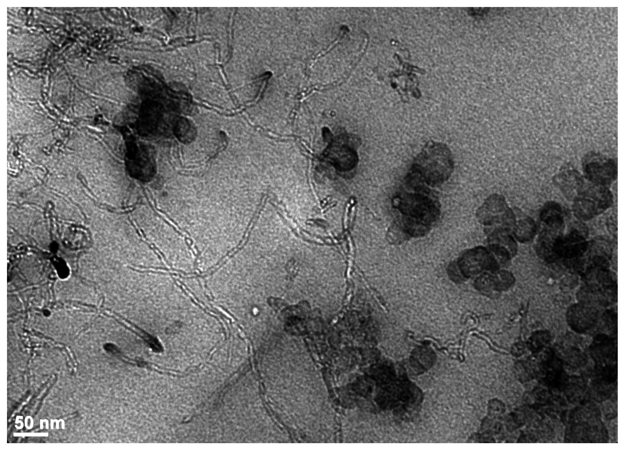
It has to be mentioned that other approaches intended to modify the filler surface, have been developed in order to reduce the tendency of carbon-based particles to assemble into agglomerates. Chemical bonding between the filler and the polymer chains enhances interfacial interactions between the two components but disrupts the delocalized π-electron system and affects the electrical properties. The use of surfactants acting as a non-covalent treatment has been shown to be an effective way to ensure homogeneous and stable dispersion throughout a solvent and in composite host materials [30,31]. This non-covalent modification of the carbon species is of great advantage because no disruption of the sp2 graphene structure occurs and the filler properties are preserved contrary to covalent functionalization. But Dyke and Tour [32] explain that in the case of carbon nanotubes, exfoliation of the bundles must occur previous to surface treatment in order to obtain individual tubes because the outermost nanotubes in a bundle are probably more treated than the innermost tubes. In that case, the nanotubes remain predominantly bundled after the surfactant treatment. This statement has been confirmed for MWCNT/polystyrene (PS) composites prepared in the absence and presence of a surfactant added before the sonication process [33]. A transmission electron microscopy (TEM) analysis reveals the formation of ropes made of several nanotubes entangled together upon application of a surfactant while an almost random distribution with some remaining agglomerates nevertheless, is observed without any treatment (Figure 1). This points out that the adsorption of the surfactant by the carbon species should occur after the dispersion process in order to get a surfactant- and polymer-stabilized system.
Incorporating simultaneously mixtures of two different fillers has been shown to improve the state of dispersion and promotes the formation of a continuous hybrid filler network resulting in better mechanical properties and, in the case of mixtures of carbon-based particles, in better electrical conductivity than composites filled with any single filler [34,35]. Figure 2 displays a TEM image of a styrene-butadiene rubber (SBR) filled with a dual loading (5 phr of CB + 5 phr of MWCNTs) in which carbon nanotubes are seen to connect CB aggregates. The double filling method was also used by Zhan et al. [36] who prepared CB and CNTs filled nanural rubber (NR) composites through an ultrasonic assisted mixing process then by Galimberti et al. [13,14,37] who add minor amounts of nanofillers (MWCNTs, nano graphite or organoclay) to a polyisoprene heavily filled with CB (60 phr). In all cases, the authors report synergistic effects between the two different types of fillers and initial modulus values much larger than those calculated by simple addition of the two initial moduli of the composites containing only a unique filler. An interesting application of the use of hybrid filler is the incorporation of small amounts of CNTs in a high silica-filled rubber in order to bring to nonconductive systems, some electrical conductivity required for the development of antistatic materials [38]. A synergistic enhancement of the percolation threshold has been reported by Sagalianov et al. [39] in hybrid polymeric nanocomposites based on carbon nanotubes and graphite nanoplatelets. More recently, carbon nanofibers were incorporated into CB-silica composites in order obtain conductive thin coatings by reducing the carbon-black content [40].
4. Tensile Properties
The first consequence of the incorporation of hard filler particles in a soft polymeric medium is the increase in the elastic modulus. Another contribution can arise from polymer-filler interactions that leads to additional cross-links in the network structure. The increase in the effective degree of cross-linking can be evaluated by equilibrium swelling by a solvent and by measurements of chain orientation that has been shown to be sensitive to the chemical junctions and also to the number of polymer-filler attachments [5,41]. In silica-filled poly(dimethylsiloxane) (PDMS) rubbers for example, the interaction between the polymer and the filler is ensured by hydrogen bonds between the silanols present on the silica surface and the oxygen atoms of the PDMS chains. In order to meet application requirements and thus impart specific properties to the resulting material, the polymer-filler interface can be tailored by using treated silica in which part of the silanols are deactivated to decrease the interactions. The use of coupling agents in combination with silica, is commonly used in non-polar polymers like hydrocarbon rubbers, in order to enhance the degree of adhesion between the polymer and the filler [42]. Due to their structural characteristics –high aspect ratio and high specific surface area that impacts the amount of interfacial area with the polymer- carbon nanostructures are expected to impart if they are finely dispersed in the elastomeric matrix, significant enhancements in various properties with regard to conventional fillers.
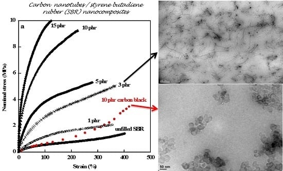
Hydrocarbon rubbers are commonly reinforced by CB and one specific feature brought by active fillers is the increase in stress observed at high deformations (see Figure 3a the stress-strain curve of the SBR/10 phr CB composite). The increase in stress at high elongations is attributed to limited chain extensibility observed for the composite on account of the increase in the effective degree of cross-linking thus decreasing the apparent molecular weight between cross-links. This behavior that reflects the polymer-filler interactions is somewhat the signature of reinforcement. The abrupt increase in stress displayed by unfilled NR (Figure 3b) is ascribed to the strain-induced crystallization of polymer chains that is an important characteristic of natural rubber due to its uniform microstructure. The crystallization process starts at a lower deformation in the presence of carbon black which may be regarded as resulting from a higher chain orientation in the direction of strain allowing the conformational change required for the formation of the crystallites [43]. Chain orientation increases with additional cross-links created by NR-CB interactions. On the other hand, polymer chains are overstrained by strain amplification effects caused by the inclusion of undeformable filler particles [44].
As seen in Figure 3 that displays the stress-strain curves of SBR and NR composites, considerable improvement in stiffness, increasing with the filler loading, is imparted to both matrices by addition of multiwall carbon nanotubes (MWCNTs) with much higher levels of reinforcement than those provided by the conventional carbon black particles. But the CB-filled SBR sample exhibits an increase in stress at high strains contrary to the unfilled SBR that does not exhibit strain-induced crystallization. The data displayed in Figure 3 were obtained from classical tensile tests performed at room temperature on a tensile Instron machine, model 5565 equipped with a 100 N load cell and a video extensometer. The strips (length around 20 mm between the jaws, width around 5 mm, and thickness between 200 and 300 μm) were marked with two dots with a white marker for their recognition by the video extensometer then stretched at a strain rate of 0.1 s−1. The nominal stress σ was calculated from σ = f/A, where f is the elastic force and A is the undeformed cross-sectional area.
The stress-strain behavior of unfilled elastomeric networks has been reproduced by various theoretical models [45,46,47,48,49]. A recent paper carried out a comparison of six different models in order to determine which of them represents the actual behavior of their material [50]. It was concluded that the Mooney-Rivlin model [45,46] is the most accurate model to account for the mechanical behavior of Santoprene 101-73.
For the Mooney-Rivlin model, the nominal stress σ is given by:
where λ is the extension ratio (ratio of the final length of the sample along the direction of stretch to that of the initial length before deformation) and 2C1 and 2C2 are constants independent of λ. 2C1 has been taken as an estimate of the high-deformation modulus (the phantom network model limit) and (2C1 + 2C2) has been used as an estimate of the low-deformation modulus (the affine network model limit) [1].
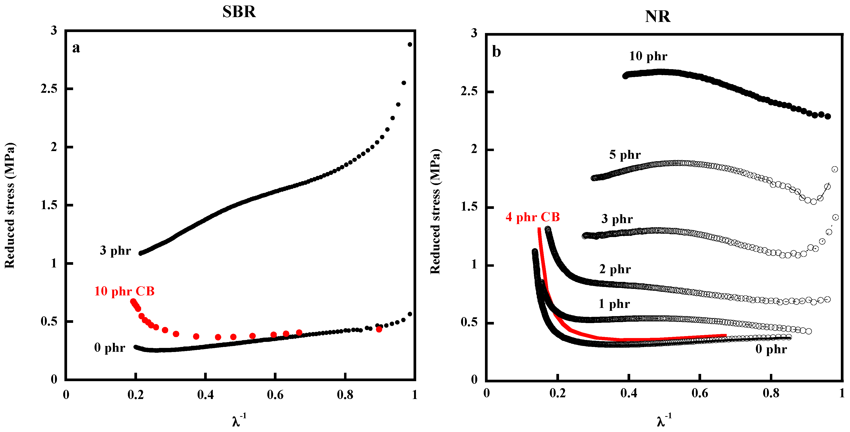
In a Mooney-Rivlin representation, the reduced stress, [σ*], defined by the quantity [σ*] = σ/(λ − λ−2) is plotted against of 1/λ. Equation (1) was established for unfilled elastomers but it has been widely used in filled elastomeric materials (see Reference [1] and all the papers of Mark et al. on filled elastomers and [51]). Dannenberg [52] explains that Equation (1) should apply to a filled vulcanizate if it can be assumed that the major function of the dispersed phase is to increase the effective strain of the rubber phase.
Mooney-Rivlin plots for unfilled and filled materials are displayed on Figure 4. They are seen to better visualize specific features of the stress-strain curves. The upturn in the modulus observed at high deformations for the SBR/CB composite cannot be ascribed in this case to crystallization but to limited chain extensibility of chain bridging filler particles thus demonstrating strong interactions between carbon black and the elastomeric phase (Figure 4a). The absence of upturn in the modulus at high elongations for the MWCNT/SBR composite denotes a weak polymer-filler interface and the strong decrease in stress observed at low deformations is attributed to the destruction of the filler network or at least of agglomerated filler structures. The Mooney-Rivlin plots of the NR/MWCNT composites display, at least for the lowest filler loadings, upturns in the modulus occurring at a lower extension ratio than that of NR/CB sample. According to the SBR results, the increase in stress at high deformations observed for the NR composites, is only attributed to the strain-induced crystallization of polymer chains. The question is to understand why the presence of fillers favors the crystallization process. In the case of CB as well as for MWCNTs, orientational effects can explain the decrease in strain values at the onset of crystallization. But an increase in chain orientation in the CB-filled composites can be attributed to a decrease in the apparent molecular weight between chemical and physical cross-links, in the case of MWCNTs, it probably arises from their strong ability to orientate along the direction of stretch. Orientation of anisotropic fillers that can be evidenced by TEM or AFM of stretched samples [33,53], is expected to affect the orientation of polymer chains as well and consequently the mechanical properties of the composite.
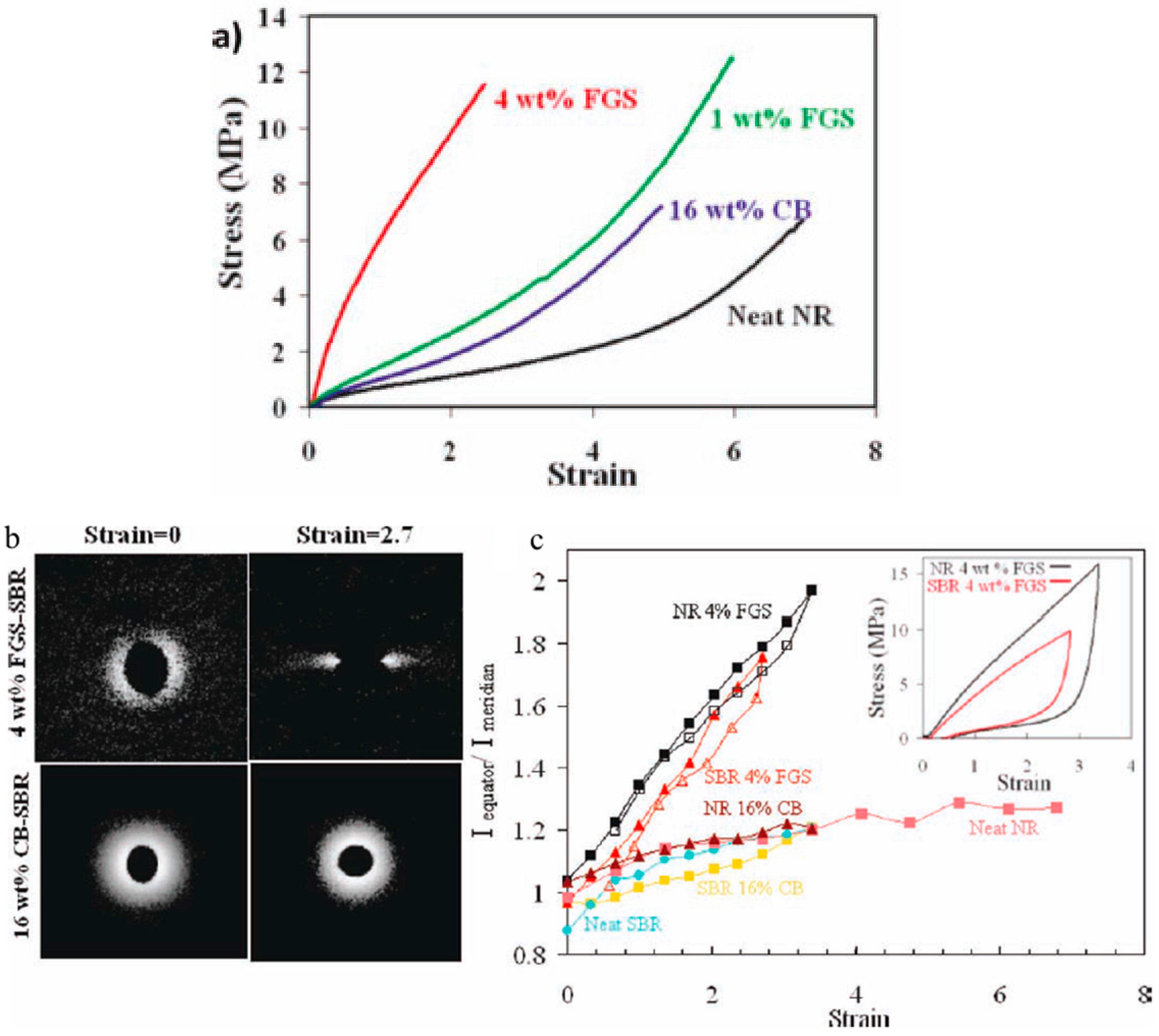
Ozbas et al. [54] have compared the effect of functionalized graphene sheets (FGS) and that of carbon black on the strain-induced crystallization of NR by coupled tensile tests and X-ray diffraction experiments. It is shown that only 1 wt % FGS imparts higher modulus and strength than 16 wt % CB (Figure 5a) and induces crystallization at lower strain (ε = 1.25 for the FGS-NR sample and 1.75 for the CB-filled NR). The authors mention the significant contribution of the alignment of FGS upon stretching to the mechanical properties of the nanocomposites. Small angle X-ray scattering shows that FGS is aligned in the stretching direction, whereas CB does not show alignment or anisotropy (Figure 5b). The ratio of the intensity at the equator (I90°) to the intensity at the meridian (I0°) becomes larger during stretching for both FGS-filled SBR and NR samples indicating that FGS sheets are oriented along the stretching direction, whereas anisotropy is not observed for CB (Figure 5c).
A comparative investigation on strain induced crystallization for graphene and carbon nanotubes filled natural rubber composites was also carried out by Fu et al. [55] on composites prepared by ultrasonically-assisted latex mixing. The incorporation of graphene is shown to result in a faster strain-induced crystallization rate and a higher crystallinity compared to CNTs. The authors conclude to stronger polymer-filler interactions in the graphene/NR composites than in CNTs/NR composites on the basis of their swelling behavior. But a swelling restriction by solvents could also arise from occluded rubber entrapped inside filler agglomerates. On the other hand, the small difference, reported by the authors, between the swelling ratio of the two types of composites is not consistent with the strong difference between their tensile properties thus showing that other parameters have to be taken into account.
In an interesting paper of Scotti et al. [56], shape controlled spherical and rod-like silica nanoparticles with different aspect ratios were synthesized by a sol-gel method in order to prepare silica/SBR composites by the blending method. The authors studied the influence of the particle morphology on the reinforcing effect independently of the silica surface chemistry and considering the aspect ratio as the only geometrical variance. The increase of the reinforcing effect of the rod-like particles by increasing their aspect ratio is related to both the self-alignment of anisotropic particles along the major axis direction and to their very large filler/polymer interface, compared to that of spherical particles. It is demonstrated that the mechanical reinforcing effect is basically related to the formation of a continuous percolative network of silica nanoparticles.
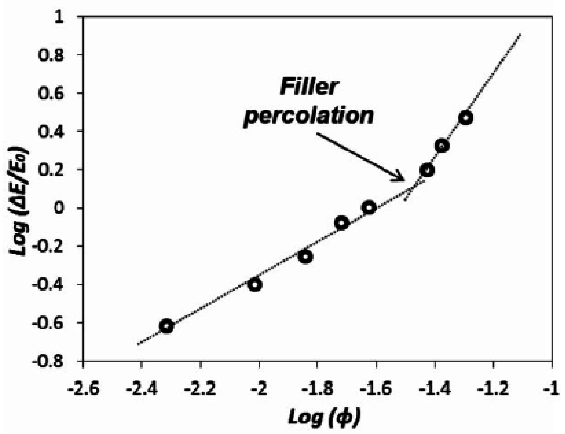
The percolative network, formed when filler aggregates join together either by direct contact or via layers of polymer shell around them, occurs at very low concentrations with anisotropic filler particles. It is responsible of the strong increase in the composite initial modulus (Figure 3) and of the strong decrease at low strains of the reduced stress (Figure 4). Galimberti et al. [37] who also report a detectable impact of carbon nanotubes on the initial modulus of filled poly(1,4-cis-isoprene), apply the model of Huber and Vilgis [57] that predicts that the excess of initial modulus (E − E0)/E0, where E and E0 are the initial modulus of the composite material with and without CNTs respectively, has a linear dependence on the filler content below the percolation threshold and scales with a power low for higher concentrations (Figure 6).
The inclusion of rigid particles is quantitatively taken into account by the Guth model [58] only based on the aspect ratio, f, and volume fraction, φ, of filler. It has been widely used to estimate the change in modulus in filled elastomers, the quadratic term being added to account for filler-filler interactions:
E and E0 are the moduli of the composite and the unfilled elastomer, respectively. The Guth equation predicts a strong increase in modulus at high volume fractions of filler.
E = E0 (1 + 0.67fφ + 1.62 f2φ2)
A strong deviation from Equation (2) is expected at volume fractions above that corresponding to the formation of a filler network.
The data of Figure 3 reveal a complete change in the stress-strain behavior of the MWCNT-filled rubbers with regard to the CB-filled samples, resulting in a significant increase of the stress at low strains and a considerable drop of the elongation at break. This fact has also been mentioned by Fritzche et al. [38] and by Rooj et al. [59].
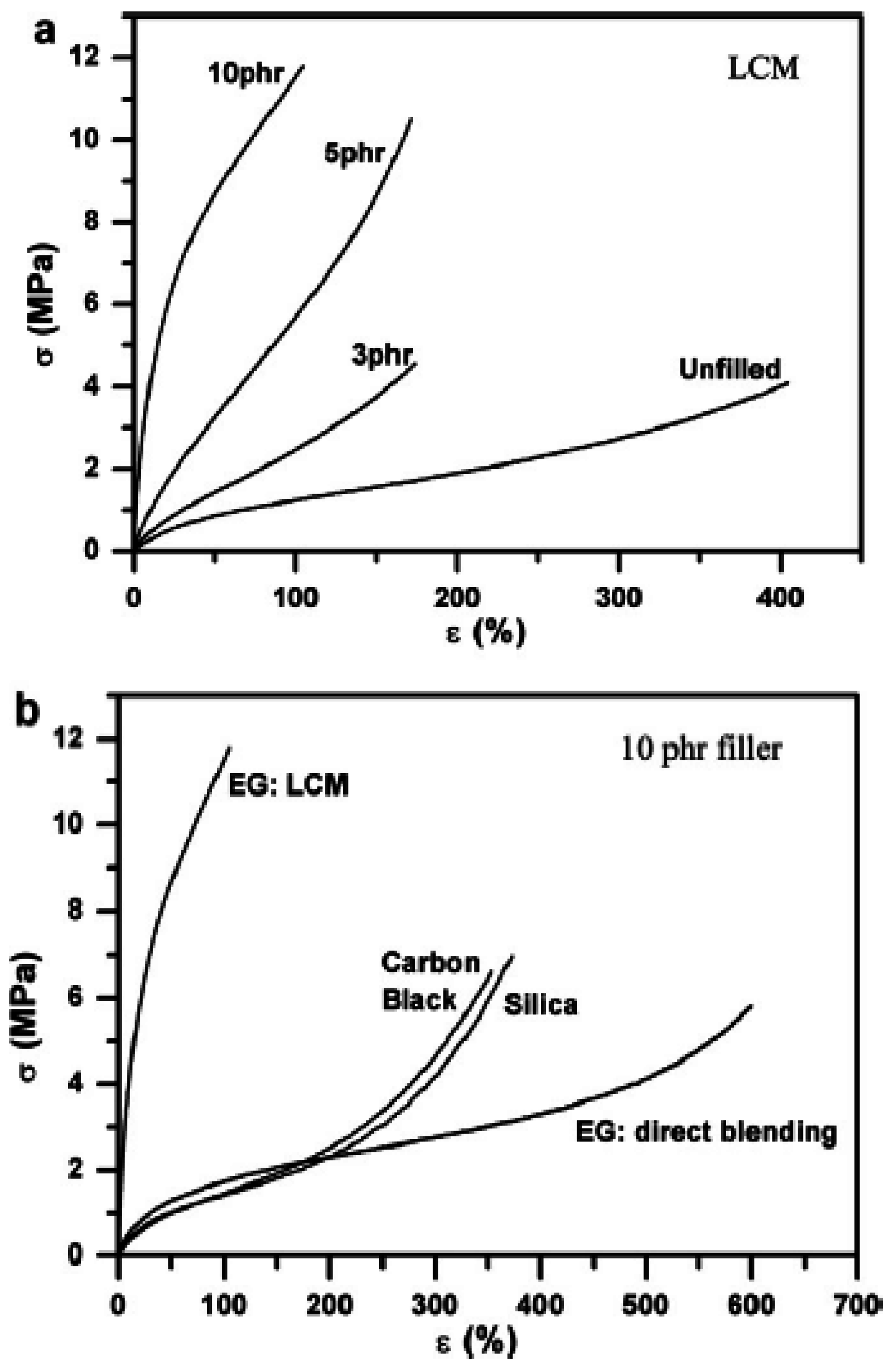
The importance of the processing conditions on the properties of the final material is illustrated in the work of Yang et al. [60] who studied composites of nitrile-butadiene rubber (NBR) filled with expanded graphite (EG) prepared by latex compounding and also by direct blending. It was shown that the tensile strength increases substantially with EG content for nanocomposites prepared by the latex compounding method (LCM) (Figure 7a). The NBR/EG (10 phr) composite exhibits, as in Figure 3, a strong increase in stress at low strains, and a much higher reinforcement efficiency than the composite prepared by blending and those reinforced with traditional fillers for rubbers such as carbon black and silica (Figure 7b). The authors attribute the different tensile properties of NBR/EG vulcanizates prepared by latex compounding and direct blending to the different dispersion quality of graphite sheets. Additionally, polar groups on the EG surface (–OH and –COOH) are expected to interact with the polar cyanide group (C≣N) of the NBR macromolecular chains and form a strong interfacial adhesion. Interestingly, the ratio of the modulus at 100% elongation (σ 100%) of the NBR/EG (10 phr) sample prepared by latex compounding to that of the unfilled elastomer (σ0 100%), is of the same order of magnitude as that of the SBR and NR composites filled with 10 phr of MWCNTs (Figure 3). This ratio may be considered as a quantitative measure of the reinforcement effect.
All the above considerations lead to the belief that the reinforcement of rubber matrix in the presence of anisotropic filler particles depends mainly on the hydrodynamic effect arising from the inclusion of rigid particles, from their state of dispersion and their orientation under strain and from filler-filler interactions leading to the formation of a filler network. Almost all studies report a strong reduction of the strain at break most probably ascribed to the presence in the material, of remaining agglomerated structures that act as defects and failure points.
Filled and crystallizing unfilled elastomers display a characteristic stress-strain behavior after a pre-stretching. If the sample is uniaxially stretched to a given strain, ε1, then released and stretched again to ε2, released and stretched to ε3…, reloading the sample leads to smaller stress values than those of initial loadings below the maximal strain values, thus exhibing the so-called stress-softening phenomenon known as the Mullins effect. Figure 8 gives an example of four successive stretching cycles (shown in different colors) performed at various deformations on a poly(dimethylsiloxane) (PDMS) filled with 40 phr of silica.
Several interpretations have been proposed to explain the stress-softening of rubbers from breakage of both the filler clusters and the rubber-to-filler bonds, chain slippage process onto the filler surface, strain amplification to chain disentanglements [44,51,61,62,63,64,65,66,67,68,69]. But despite the numerous studies devoted to an understanding of the Mullins effect, there is still no general agreeement on the origin of this effect probably because it may arise from different phenomena depending on the characteristics of the polymer-filler system. The literature on the Mullins effect was reviewed by Clément et al. [70], Diani et al. [71] and more recently by Harish et al. [72].
On the basis of experiments based on atomic force microscopy under strain, Clément et al. [70] showed that the Mullins effect is much more important with silica particles that has not undergone any surface treatment, in other words in particles that give rise to strong interaction with the PDMS chains. This points out the importance of the polymer-filler interface in systems with strong reactive components. The Mullins effect, in conventional composites, has been attributed to the breakage or the slippage, from the particle surface, of chains that attain their limit of extensibility by strain-amplification effects. Strain-amplification effects depend on the local volume fraction of filler around the polymer chains, in other words on the state of filler dispersion. On account of strain amplification phenomenon, the rubber is much more deformed in regions of the sample of high volume fractions of filler and consequently the chains reach their limit of extensibility at low strains and detach from the filler surface thus causing the loss of elastic chains. The other regions of lower filler volume fraction are not concerned at this stage of deformation but become affected at increasing strains. Atomic force microscopy carried out on stretched composites gives evidence that the strain field is highly heterogeneous, depending on the local concentration of filler and that the strain undergone by elastomer chains can be very high locally, in the regions where distances between aggregates are very short [73]. The overstraining effects make chains to reach their limit of extensibility at low strains and detach from the filler surface resulting in a loss of elastic chains. It is worthwhile to notice that equilibrium swelling measurements performed on networks pre-stretched at different strains confirm the loss of elastic chains [74,75]. The concept of strain amplification was also used by Maiti et al. [76] to analyze the Mullins softening in a silica-filled PDMS rubber material. The authors assume that during the first loading curve, the soft part of the matrix is being pulled out of the hard region thus progressively decreasing the relative fraction of the hard domain. The difference with the work of Clément et al. [70] is the use of the spatially uniform strain amplification which is not correct since inhomogeneous strain fields were demonstrated by atomic force microscopy. Dargazany and Itskov [77,78] have proposed a micro-mechanical model for carbon-black fillers where damage of the polymer network is considered as a consequence of chain sliding on or debonding from aggregates.
Harish et al. [72] have developed a heterogeneous (or multiphase) constitutive model by considering clustering and percolation behavior of filler particles. According to the authors, contrary to crystallizing unfilled elastomers for which crystallization leads to distinctive physical and chemical changes, in filled elastomers, filler breakage can be considered as one of the, if not primay, causes for Mullins softening. The filled elastomeric material is hypothesized as a three-phase material consisting of free rubber, bound rubber and filler aggregate phases but bound rubber properties are shown to not significantly impact the material response.
A very recent study [79] uses strain-induced from mechanoluminescent cross-linkers in silica-filled poly(dimethylsiloxane) to demonstrate that covalent bond scission occurs predominantly on the first cycle to a particular strain, when the material displays the greatest hysteresis. The cross-linkers contain dioxetanes that emit light upon force-induced bond scission.
Elastomers filled with carbon nanomaterials (carbon nanotubes, graphite nanoplatelets or graphene oxide) have been shown to exhibit the Mullins stress-softening effect [10,35,53,80,81,82,83,84]. As mentioned in almost all studies, the important feature displayed by composites filled with carbon nanomaterials is the high degree of permanent deformation with regard to carbon black or silica-filled elastomers (Figure 9).
Despite the fact that the existence of interactions between the graphene surface and the polymer chains is still a subject of debate, the different interpretations discussed above for conventional composites can be applied to explain the Mullins effect in samples filled with carbon nanomaterials. Nevertheless, one has to take into account their geometry and especially their high aspect ratio making them prone to get aligned when subjected to tension. Another significant effect of the strain is a debundling of the agglomerates resulting in a pulling out of the gum entrapped inside the agglomerates that reduces as mentioned in reference 76, the fraction of hard domains. This interpretation is supported by the fact that the rupture of the sample in the second stretching occurs at a much higher value of strain than that obtained in the first stretching curve [85].
5. Dynamic Mechanical Properties
As reported above, the filler-filler interactions cause the formation of a filler network that enhances the modulus at low strains and is responsible of the strong decrease at low strains of the reduced stress (Figure 4). The filler network is generally evidenced through the strain dependence of the storage modulus G’ that exhibits a non-linear behavior called the “Payne effect” [86]. G’ displays a characteristic amplitude dependence, decreasing from the value of the modulus at strains approaching zero, G’0, to a plateau value G’∞ with increasing strain amplitude [87]. The amplitude of the Payne effect defined as (G’0 − G’∞) has been found to be affected by the specific surface area, concentration and surface treatment of the filler particles as well as by the temperature. The Payne effect is obviously linked to the state of dispersion of the filler particles in the polymer matrix. The use of coupling agents in silica-filled hydrocarbon rubbers for example, decreases the amplitude of the Payne effect by depressing filler-filler interactions [88]. In the case of an “ideal” dispersion as that obtained by the generation of filler particles by the sol-gel process, no Payne effect is observed in the whole range of shear strain range investigated (Figure 10).
The drop in the elastic modulus has been mostly explained by a breakdown upon oscillatory shear, of the filler network formed by direct particle contacts or via immobilized elastomeric layer where the particle surface is recovered with adhering elastomeric molecules [89]. Nevertheless, it has to be pointed out that a non-linear behavior can also be observed for filler volume fractions lower than the percolation threshold [90] and from this point of view, below the percolation threshold, the Payne effect can be explained by a disruption of the filler agglomerated structures.
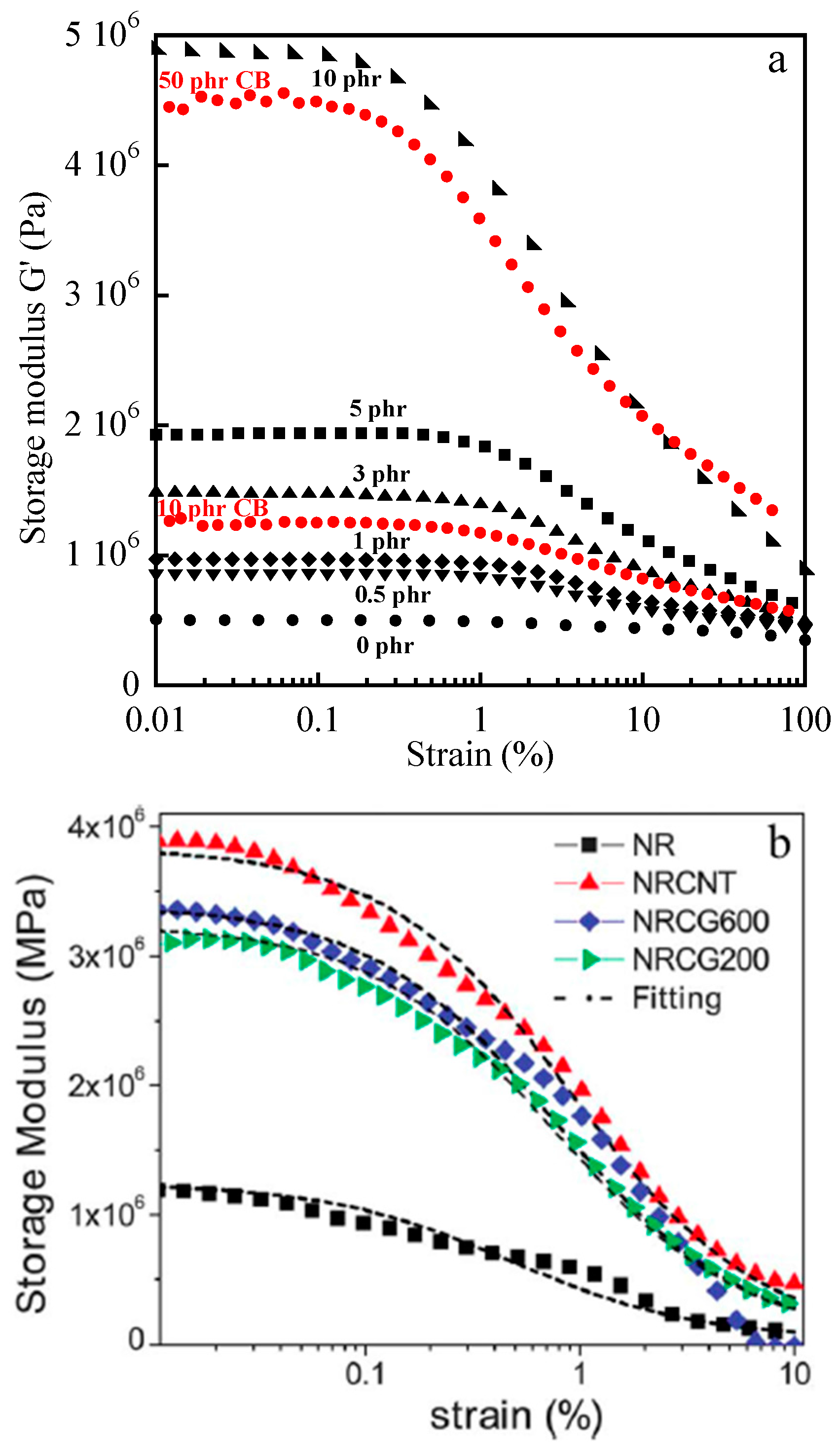
A Payne effect has been reported for elastomers filled with different carbon materials. In Figure 11a that compares the Payne effect in NR composites filled with CB and MWCNTs, it is shown that the Payne effect strongly increases with the amount of filler and with the anisometry of the particles since it is much more important with MWCNTs than with CB at a same filler loading.
Surprinsingly, in poly(1,4-cis-isoprene) filled with a nanographite with a high shape anisotropy, a noticeable Payne effect is obtained for a filler content of 40 and 60 phr [13], which corresponds to much higher volume fractions than those involved in NR/MWCNTs composites (see Figure 11a) despite the high aspect ratio of nanographite, mentioned by the authors, expected to allow the formation of a filler network at a very low filler loading. The comparative non-linear dynamic viscoelastic response of neat NR and composites filled with CNTs alone and together with reduced graphene oxide, are shown in Figure 11b. Graphene oxide (CG600 and CG20) was reduced thermally at two different temperatures 600 and 200 °C [91]. The experimental results were fitted to the Maier and Göritz model based on filler-rubber interactions and on an adsorption mechanism of network chains on the surface of filler particles [92]. The decrease of the dynamic storage modulus is attributed to a desorption of unstable bonded chains. It was deduced that the decrease in storage modulus with shear amplitude indicates an order of filler-rubber interaction as NR-CNT > NR-CG600 > NR-CG200 [91]. Nevertheless, it has to be pointed out that the neat elastomer also displays a non-linear behavior contrary to what is expected and observed in Figure 11a.
The results published in the literature do not allow to assess the influence of the nature of the anisotropic carbon particles on the Payne effect since the non-linear dynamic behavior is strongly related to the state of dispersion. Agglomeration leads to an increase in the volume fraction corresponding to the formation of a three-dimensional network structure that signicantly affects the dynamic viscoelastic properties. At this point, it is interesting to mention that in the work of Scotti et al. [56] dealing with shape controlled and rod-like nanoparticles with different aspect ratios in SBR, the storage modulus at low strains, G’0, increases with the aspect ratio but the G’∞ values are very similar for all the composites filled at a same filler loading. This means that the differences in reinforcement are less effective once the network is broken down which was expected since the filler synthesis has been targeted to obtain nanoparticles only different in shape.
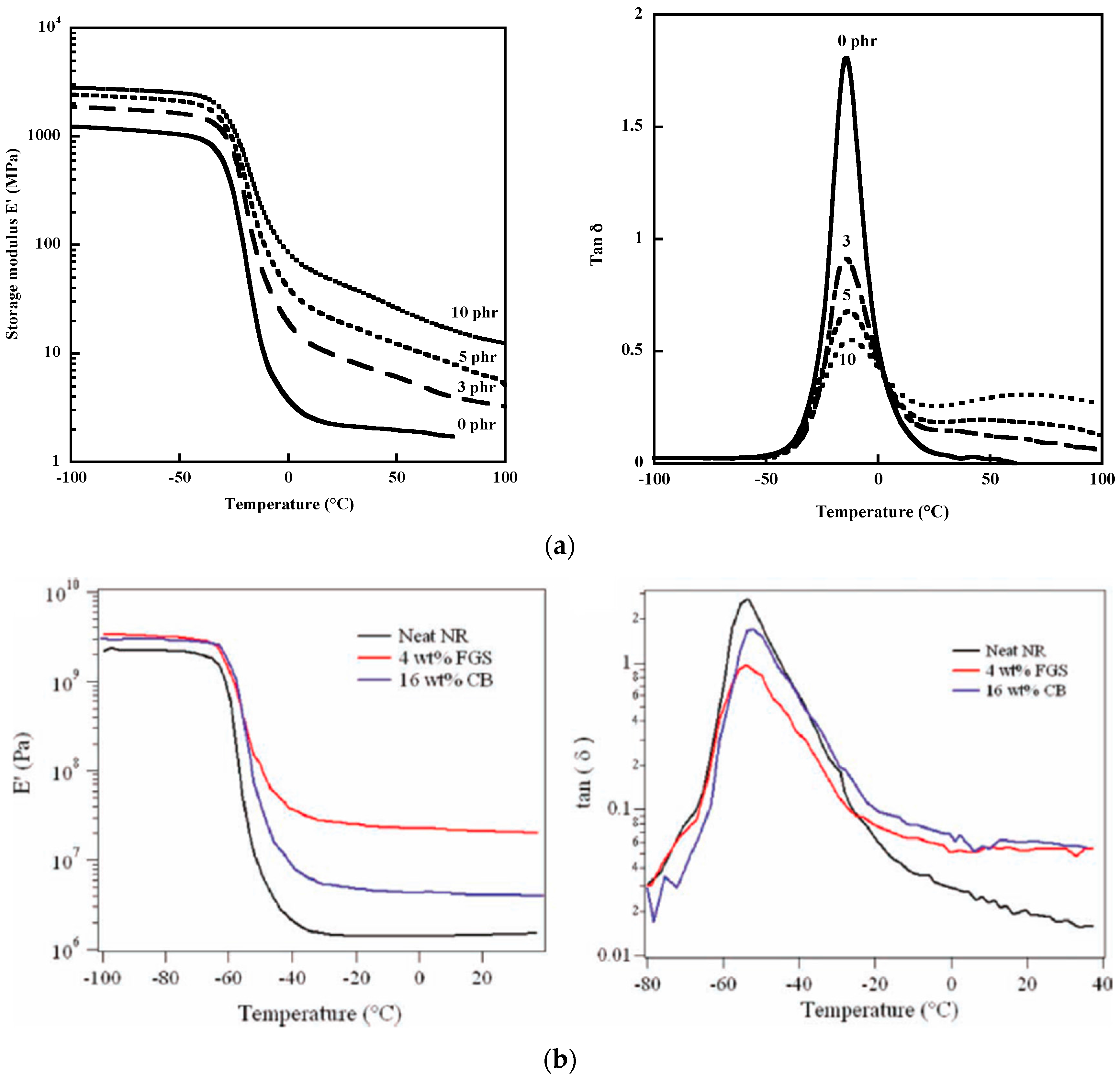
Temperature dependences of the storage modulus and of the loss factor, tand δ, are displayed in Figure 12 for SBR/MWCNTs composites (a) and for NR composites filled with functionalized graphene sheets (FGS) (b). For all the samples, the strong decrease in the storage modulus is associated with the glass transition phenomenon of the elastomer chains. Below and above Tg, the value of E’ increases with increasing nanotube loading but the increase in the rubbery region is much more important than in the glassy state because it contains the contribution arising from the Payne effect [93]. Dynamic mechanical results reported by Ozbas et al. [54] for NR composites show a much higher increase in the storage modulus for NR filled with 4 wt % FGS (functionalized graphene sheets) than for a loading of 16 wt % CB even at four times lower volume fraction (Figure 12b) which confirms the results displayed on Figure 11a. The authors believe that in the rubbery region, strain amplification combines with the effect of immobilized rubber to give the 30- to 90-fold increases in the effective volume fraction. Nevertheless, it is also shown that Tg is not substantially shifted by the addition of either FGS or CB. Two papers of Araby et al. [94,95] in which graphene platelets (GnPs) have been incorporated in EPDM [94] and in SBR [95] observe an increase in the storage modulus by 2536% and 159% at 12 vol % GnPs in EPDM and around 190% and 650% at 10.5 vol % in SBR in the glassy and rubbery regions, respectively. These improvements are attributed to a high level of interaction between matrix chains and GnPs. However, it should be mentioned that the filler contents used in these studies and expressed in vol % are high while nanofillers, if well dispersed, are expected to impart to the host matrix strong reinforcement at very low filler loading. Besides the impressive and unusual enhancement of the storage modulus of the EPDM/GnPs (12 vol %), the authors mention an increase in Tg by 2.2% for the 5.7 vol % GnPs and an increase of 4 °C at 10.5 vol % GnPs in SBR, attributed to a decrease in the mobility of elastomer chains attributed to good interfacial polymer-filler interaction [94,95]. Potts et al. [26] have shown that for a 5 wt % reduced graphene oxide/NR nanocomposite, the storage modulus increases by a factor of 3.4 and 2 at −100 °C, but by factors of 19.5 and 4.7 at 25 °C by solution treatment and two-roll mill processing. Analysis of tan δ peaks showed little to no change in Tg with loading but the authors mention that the shape and height of the peak change significantly with incorporation of GO platelets which they attribute to favorable polymer-filler interactions. Wu et al. [96] also prepared a series of NR/GO composites filled with different GO sizes through latex co-coagulation technology in order to evaluate the effect of GO size on the mechanical properties of the resulting composites. The storage modulus at 20 °C of neat NR and of the composites filled with 2 phr of GO having three different sizes (92.68, 164.39 and 323.74 nm in the composites) are 1.01, 1.82, 1.71 and 1.52 MPa, respectively. The enhancement of the storage modulus is modest with regard to that observed by Potts et al. [26].
All the studies reported above, point out some discrepancies and contradictory results due to the fact that the composite properties are affected by several factors including the type of particles, the type of polymer, the interfacial interactions and more significantly the filler dispersion that depends on the processing techniques.
6. Electrical Properties under Strain
Measurements of resistivity under strain brings further insight into the physical processes involved in deformation of filled elastomers. Carbon nanomaterials have largely demonstrated their ability to provide, when incorporated into ordinarily insulating polymeric media, electrical conduction at a much lower filler content than carbon black particles [12,16,35,97,98,99,100,101,102,103,104]. At a given amount of conductive particles called the percolation threshold, a continuous network of filler is formed across the matrix and the material undergoes a sudden transition from an insulator to a conductor. The percolation threshold in various elastomers (NR, SBR and EPDM) filled with MWCNTs has been found to be around 0.5 phr [102]. It has also been found to be 0.5 phr by Al-solamy et al. [105] in acrylonitrile butadiene rubber filled with graphite nanoplatelets. In the review of Potts et al. [101], the reported electrical percolation thresholds achieved with graphene-based nanocomposites do not differ significantly from those observed for CNT/polymer composites. Sadasivuni et al. [12] report more dispersed values of the percolation threshold for graphene and graphite derivative elastomer nanocomposites.
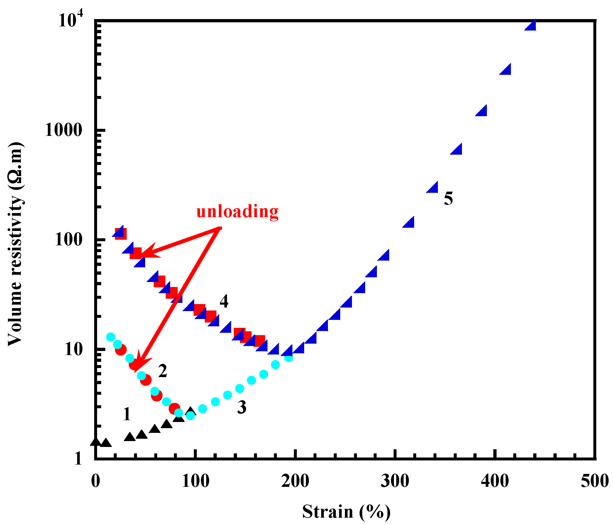
Filler parameters such as particle size, structure, concentration, dispersion, orientation, are key factors in determining the electrical properties of composites. Resistivity is also sensitive to a mechanical deformation that changes the filler distribution. A typical strain dependence of volume resistivity of a NR/MWCNTs (3phr) composite is shown in Figure 13. At the filler content of 3 phr, the composite is above the percolation threshold, determined around 0.5 phr [102]. During the first stretching to 100% strain (step 1), the resistivity increases gradually thus reflecting a decrease in the filler contacts. This result may be regarded as arising from an alignment of filler structures in the stretching direction. White et al. [103] have presented a three-dimensional simulation and calculation of electrical conductivity above the percolation threshold for networks containing finite, conductive cylinders as a function of axial orientation. It is shown that at a fixed volume fraction and aspect ratio, the electrical conductivities exhibit a substantial drop with increasing axial alignment. As the rods become highly aligned, the network structure is destroyed, causing the electrical conductivity to decrease. The authors highlight the importance of axial orientation of conductive cylindrical particles in a nonconductive matrix in determining the electrical conductivity and more generally in determining composite properties.
Figure 13 shows that unloading gradually the sample leads to an uncrease in resistivity and after total removal of the stress, the resistivity is much higher than that of the undeformed material thus showing that the contacts are not reformed. A second stretch is totally reversible till the point where the first and second stretching meet (step 2) then the resistivity increases again (step 3). A second unloading from ε = 200% leads to a higher value of resistivity than that obtained in the first unloading cycle and a third stretching still displays a decrease (step 4) then increase (step 5) in resistivity. The distance between particles increases along the direction of stretch but the width and thickness are reduced but increase upon unloading till zero stress causing a loss of contacts between conductive particles and an increase in resistivity. Re-straining the sample brings again the particles in the cross-sectional area into contact thus explaining the reversible portion of the curve in Figure 13 (steps 2 and 4).
In a study related to the resistivity behavior of carbon black-filled silicone rubber submitted to cyclic loading experiments, Kost et al. [104] showed, from stress and relative electrical resistivity relaxation experiments that upon complete retraction of the sample that follows stretching step, the resistivity is higher than the original value of the unstrained virgin sample. According to the authors, during cyclic tests, orientation effects are insignificant at low extensions (less than about 25%) where the formation and destruction of the carbon network is the dominant process. At higher strains, orientation effects become important, causing a resistivity reduction.
Elastomeric composites based on ethylene-propylene-diene monomer (EPDM) filled with MWCNTs have also been shown to display a decrease in conductivity with increasing strain, a linear relation being found between conductivity and deformations up to 10% strain [98]. Cyclic experiments showed that the change in resistivity presents a reversible portion attributed to piezoresistivity and an irreversible one attributed to damage.
De Focatiis et al. [81] have compared the resistivity-strain response of elastomers filled with CB to materials filled with MWCNTs. In the CB-filled elastomers, the piezoresistive loading path was relatively independent of prestrain, whereas the unloading path depended strongly on prestrain. In the MWCNT-filled elastomers, the piezoresistive loading and unloading paths were relatively close to each other. Cyclic experiments reveal that the resistivity was lower during loading than during unloading in the CB-filled materials whereas the reverse was true for the MWCNT-filled elastomers. The authors believe that the different behavior may be related to the very different aspect ratio of the filler particles. The cyclic experiments were intended to explore the applicability by the materials as strain sensors by looking for ranges of deformation where the electrical response was repeatable.
7. Conclusions
This review article has addressed recent research carried out on elastomers filled with carbon nanomaterials such as carbon nanotubes, graphitic nanostructures, graphene and graphene oxide. At a same filler loading, these nanomaterials impart to the rubbery matrices, a much higher increase in the elastic modulus than that provided by the conventional carbon black particles. The improvements are mainly related to the anisotropic character of the fillers and to their ability to orientate along the direction of stretch as well as to the formation of a filler network achieved at a very low filler loading on account of the high aspect ratio of the nanoparticles. The state of filler dispersion has also a large influence on the physical performance of the elastomeric compound and the presence of agglomerated structures explains the strong reduction in the strain at rupture in almost all reported studies dealing with carbon nanomaterials. That points out the importance of the manufacturing techniques of rubber nanocomposites that aim at keeping fillers at nanoscale in polymeric matrices. The interfacial interactions between the polymer chains and the filler particles that play a major role in conventional composites are weaker with carbon nanomaterials than with carbon black as demonstrated by the absence of upturn in the reduced stress at high elongations. The data presented in the literature do not allow to compare the reinforcing efficiencies of the different carbon nanostructures since the composite properties are strongly related to the state of filler dispersion. This type of evaluation can only be done in the case of “ideal” dispersions.
One of the major attribute of the carbon nanomaterials with high aspect ratio is to provide electrical conduction at a much lower filler loading than that provided by carbon black particles. But as for other properties, the state of filler dispersion that depends on the processing conditions has a strong effect on the electrical properties. According to the reported studies, the different carbon nanstructures provide similar electrical property enhancements. Only more efficient mixing techniques in view of better state of dispersion would allow an assessment of the role of filler morphology on electrical and mechanical properties.
Conflicts of Interest
The authors declare no conflict of interest.
References
- Mark, J.E.; Erman, B. Rubberlike Elasticity, A Molecula Primer; John Wiley & Sons: Hoboken, NJ, USA, 1988. [Google Scholar]
- Kraus, G. Reinforcement of elastomers by carbon black. Adv. Polym. Sci. 1971, 8, 155–237. [Google Scholar]
- Voet, A. Reinforcement of elastomers by fillers: Review of period 1967–1976. J. Polym. Sci. Macromol. Rev. 1980, 15, 327–373. [Google Scholar] [CrossRef]
- Donnet, J.-B. Black and white fillers and tire compound. Rubber Chem. Technol. 1998, 71, 323–341. [Google Scholar] [CrossRef]
- Bokobza, L. The reinforcement of elastomeric networks by fillers. Macromol. Mater. Eng. 2004, 289, 607–621. [Google Scholar] [CrossRef]
- McCarthy, D.W.; Mark, J.E.; Schaeffer, D.W. Synthesis, structure, and properties of hybrid organicinorganic composites based on polysiloxanes. I. Poly(dimethylsiloxane) elastomers containing silica. J. Polym. Sci. Part B Polym. Phys. 1998, 36, 1167–1189. [Google Scholar] [CrossRef]
- McCarthy, D.W.; Mark, J.E.; Clarson, S.J.; Schaeffer, D.W. Synthesis, structure, and properties of hybrid organic-inorganic composites based on polysiloxanes. II. Comparisons between poly(methylphenylsiloxane) and poly(dimethylsiloxane), and between titania and silica. J. Polym. Sci. Part B Polym. Phys. 1998, 36, 1191–1200. [Google Scholar] [CrossRef]
- Bokobza, L.; Diop, A.L. Reinforcement of silicone rubbers by sol-gel in situ generated filler particles. In Rubber Nanocomposites: Preparation, Properties, and Applications; Thomas, S., Stephen, R., Eds.; John Wiley & Sons (Asia): Jin Xing Distripark, Singapore, 2010; Chapter 3; pp. 63–85. [Google Scholar]
- Galimberti, M. (Ed.) Rubber Clay Nanocomposites: Science, Technology, and Applications; John Wiley & Sons: Hoboken, NJ, USA, 2011. [Google Scholar]
- Bokobza, L. Multiwall carbon nanotube elastomeric composites: A review. Polymer 2007, 48, 4907–4920. [Google Scholar] [CrossRef]
- Mensah, B.; Kim, H.G.; Lee, J.-H.; Arepalli, S.; Nah, C. Carbon nanotube-reinforced elastomeric nanocomposites: A review. Int. J. Smart Nano Mater. 2015, 6, 211–238. [Google Scholar] [CrossRef]
- Sadasivuni, K.K.; Ponnamma, D.; Thomas, S.; Grohens, Y. Evolution from graphite to graphene elastomer composites. Prog. Polym. Sci. 2014, 39, 749–780. [Google Scholar] [CrossRef]
- Galimberti, M.; Kumar, V.; Coombs, M.; Cipoletti, V.; Agnelli, S.; Pandini, S.; Conzatti, L. Filler networking of a nanographite with a high shape anisotropy and synergism with carbon black in poly(1,4-cis-isoprene)-based nanocomposites. Rubber Chem. Technol. 2014, 87, 197–218. [Google Scholar] [CrossRef]
- Galimberti, M.; Cipoletti, V.; Musto, S.; Cioppa, S.; Peli, G.; Mauro, M.; Gaetano, G.; Agnelli, S.; Theonis, R.; Kumar, V. Recent advancements in rubber nanocomposites, Rubber Chem. Technol. 2014, 87, 417–442. [Google Scholar]
- Araby, S.; Meng, Q.; Zhang, L.; Zaman, I.; Majewski, P.; Ma, J. Elastomeric composites based on carbon nanomaterials. Nanotechnology 2015, 26, 112001. [Google Scholar] [CrossRef] [PubMed]
- Papageorgiou, D.G.; Kinloch, I.A.; Young, R.J. Graphene/elastomer nanocomposites. Carbon 2015, 95, 460–484. [Google Scholar] [CrossRef]
- Chen, G.; Zhao, W. Rubber/Graphite Nanocomposites. In Rubber Nanocomposites: Preparation, Properties, and Applications; Thomas, S., Stephen, R., Eds.; John Wiley & Sons (Asia): Jin Xing Distripark, Singapore, 2010; Chapter 19; pp. 527–550. [Google Scholar]
- Viculis, L.M.; Mack, J.J.; Mayer, O.M.; Hahn, H.T.; Kaner, R.B. Intercalation and exfoliation routes to graphite nanoplatelets. J. Mater. Chem. 2005, 15, 974–978. [Google Scholar] [CrossRef]
- Niu, R.; Gong, J.; Xu, D.; Tang, T.; Sun, Z.-Y. Influence of molecular weight of polymer matrix on the structure and rheological properties of graphene oxide/polydimethylsiloxane composites. Polymer 2014, 55, 5445–5453. [Google Scholar] [CrossRef]
- Bokobza, L.; Bruneel, J.-L.; Couzi, M. Raman Spectra of carbon-based materials (from graphite to carbon black) and of some silicone composites. C J. Carbon Res. 2015, 1, 77. [Google Scholar] [CrossRef]
- Bokobza, L.; Bruneel, J.-L.; Couzi, M. Raman spectroscopy as a tool for the analysis of carbon-based materials (highly oriented pyrolitic graphite, multilayer graphene and multiwall carbon nanotubes) and of some of their elastomeric composites. Vib. Spectrosc. 2014, 74, 57–63. [Google Scholar] [CrossRef]
- Zhang, L.; Wang, Y.; Wang, Y.; Sui, Y.; Yu, D. Morphology and mechanical properties of clay/styrene-butadiene rubber nanocomposites. J. Appl. Polym. Sci. 2000, 78, 1873–1878. [Google Scholar] [CrossRef]
- Wang, Y.; Zhang, L.; Tang, C.; Yu, D. Preparation and characterization of rubber-clay nanocomposites. J. Appl. Polym. Sci. 2000, 78, 1879–1883. [Google Scholar] [CrossRef]
- Wu, Y.-P.; Wang, Y.-Q.; Zhang, H.-F.; Wang, Y.-Z.; Yu, D.-S.; Zhang, L.-Q.; Yang, J. Rubber pristine clay nanocomposites prepared by co-coagulating rubber latex and clay aqueous suspension. Compos. Sci. Technol. 2005, 65, 1195–1202. [Google Scholar] [CrossRef]
- Zhan, Y.; Wu, J.; Xia, H.; Yan, N.; Fei, G.; Yuan, G. Dispersion and exfoliation of graphene in rubber by an ultrasonically-assisted latex mixing and in situ reduction process. Macromol. Sci. Eng. 2011, 296, 590–602. [Google Scholar] [CrossRef]
- Potts, J.R.; Shankar, O.; Du, L.; Ruoff, R.S. Processing–morphology–property relationships and composite theory analysis of reduced graphene oxide/natural Rubber nanocomposites. Macromolecules 2012, 45, 6045–6055. [Google Scholar] [CrossRef]
- Lee, Y.R.; Raghu, A.V.; Jeong, H.M.; Kim, B.K. Properties of waterborne polyurethane/functionalized graphene sheet nanocomposites prepared by an in situ method. Macromol. Chem. Phys. 2009, 210, 1247–1254. [Google Scholar] [CrossRef]
- Paszkiewicz, S.; Szymczyk, A.; Špitalský, Z.; Mosnáček, J.; Kwiatkowski, K.; Rosłaniec, Z. Structure and properties of nanocomposites based on PTT-block-PTMO copolymer and graphene oxide prepared by in situ polymerization. Eur. Polym. J. 2014, 50, 69–77. [Google Scholar] [CrossRef]
- Kim, H.; Miura, Y.; Macosko, C.W. Graphene/polyurethane nanocomposites for improved gas barrier and electrical conductivity. Chem. Mater. 2010, 22, 3441–3450. [Google Scholar] [CrossRef]
- Vaisman, L.; Wagner, H.D.; Marom, G. The role of surfactants in dispersion of carbon nanotubes. Adv. Colloid Interface Sci. 2006, 128–130, 37–46. [Google Scholar] [CrossRef] [PubMed]
- Tkalya, E.E.; Ghislandi, M.; de With, G.; Koning, C.E. The use of surfactants for dispersing carbon nanotubes and graphene to make conductive nanocomposites. Curr. Opin. Colloid Interface Sci. 2012, 17, 225–232. [Google Scholar] [CrossRef]
- Dyke, C.A.; Tour, J.M. Unbundled and highly functionalized carbon nanotubes from aqueous reactions. Nano Lett. 2003, 3, 1215–1218. [Google Scholar] [CrossRef]
- Bokobza, L.; Garnaud, G.; Beaunier, P.; Bruneel, J.-L. Vibrational and electrical investigations of a uniaxially stretched polystyrene/carbon nanotube composite. Vib. Spectrosc. 2013, 67, 6–13. [Google Scholar] [CrossRef]
- Bokobza, L.; Leroy, E.; Lalanne, V. Effect of filling mixtures of sepiolite and a surface modified fumed silica on the mechanical and swelling behavior of a styrene-butadiene rubber. Eur. Polym. J. 2009, 45, 996–1001. [Google Scholar] [CrossRef]
- Bokobza, L.; Rahmani, M.; Belin, C.; Bruneel, J.-L.; El Bounia, N.-E. Blends of carbon blacks and multiwall carbon nanotubes as reinforcing fillers for hydrocarbon rubbers. J. Polym. Sci. Part B Polym. Phys. 2008, 46, 1939–1951. [Google Scholar] [CrossRef]
- Zhan, Y.H.; Liu, G.Q.; Xia, H.S.; Yan, N. Natural rubber/carbon black/carbon nanotubes composites prepared through ultrasonic assisted latex mixing process. Plast. Rubber Compos. 2011, 40, 32–39. [Google Scholar] [CrossRef]
- Galimberti, M.; Coombs, M.; Riccio, P.; Riccò, T.; Passera, S.; Pandini, S.; Conzatti, L.; Ravasio, A.; Tritto, I. The role of CNTs in promoting hybrid filler networking and synergism with carbon black in the mechanical behavior of filled polyisoprene. Macromol. Mater. Eng. 2013, 298, 241–251. [Google Scholar] [CrossRef]
- Fritzsche, J.; Lorenz, H.; Klüppel, M. CNT based elastomer-hybrid-nanocomposites with promising mechanical and electrical properties. Macromol. Mater. Eng. 2009, 294, 551–560. [Google Scholar] [CrossRef]
- Sagalianov, I.; Vovchenko, L.; Matzui, L.; Lazarenko, O. Synergistic enhancement of the percolation threshold in hybrid polymeric nanocomposites based on carbon nanotubes and graphite nanoplatelets. Nanoscale Res. Lett. 2017, 12, 140. [Google Scholar] [CrossRef] [PubMed]
- Enriquez, E.; de Frutos, J.; Fernandez, J.F.; de la Rubia, M.A. Conductive coatings with low carbon-black content by adding carbon nanofibers. Compos. Sci. Technol. 2014, 93, 9–16. [Google Scholar] [CrossRef]
- Bokobza, L. Filled elastomers: A new approach based on measurements of chain orientation. Polymer 2001, 42, 5415–5423. [Google Scholar] [CrossRef]
- Wagner, M.P. Reinforcing silicas and silicates. Rubber Chem. Technol. 1976, 49, 703–774. [Google Scholar] [CrossRef]
- Amram, B.; Bokobza, L.; Queslel, J.P.; Monnerie, L. Fourier-transform infra-red dichroism study of molecular orientation in synthetic high cis-1,4-polyisoprene and in natural rubber. Polymer 1986, 27, 877–882. [Google Scholar] [CrossRef]
- Bueche, F. Molecular basis for the Mullins effect. J. Appl. Polym. Sci. 1960, 4, 107–114. [Google Scholar] [CrossRef]
- Mooney, M. A theory of large elastic deformation. J. Appl. Phys. 1940, 11, 582–592. [Google Scholar] [CrossRef]
- Rivlin, R.S.; Saunders, D.W. Large elastic deformations of isotropic materials. VII. Experiments on the deformation of rubber. Philos. Trans. R. Soc. Lond. A Math. Phys. Eng. Sci. 1951, 243, 251–288. [Google Scholar] [CrossRef]
- Flory, P.J.; Erman, B. Theory of elasticity of polymer networks. 3. Macromolecules 1982, 15, 800–806. [Google Scholar] [CrossRef]
- Gent, A.N. A new constitutive relation for rubber. Rubber Chem. Technol. 1996, 69, 59–61. [Google Scholar] [CrossRef]
- Boyce, M.C.; Arruda, E.M. Constitutive models of rubber elasticity: A review. Rubber Chem. Technol. 2000, 73, 504–523. [Google Scholar] [CrossRef]
- Tobajas, R.; Ibartz, E.; Gracia, L. A comparative study of hyperelastic constitutive models to characterize the behavior of a polymer used in automotive engines. Proc. 2nd Int. Electron. Conf. Mater. 2016, 2, A002. [Google Scholar] [CrossRef]
- Mullins, L.; Tobin, N.R. Theoretical model for the elastic behavior of filler-reinforced vulcanized rubbers. Rubber Chem. Technol. 1957, 30, 555–571. [Google Scholar] [CrossRef]
- Dannenberg, E.M. The effects of surface chemical interactions on the properties of filler-reinforced rubbers. Rubber Chem. Technol. 1975, 48, 410–444. [Google Scholar] [CrossRef]
- Bokobza, L.; Bresson, B.; Garnaud, G.; Zhang, J. Mechanical and AFM investogations of elastomers filled with multiwall carbon nanotubes. Compos. Interfaces 2012, 19, 285–295. [Google Scholar] [CrossRef]
- Ozbas, B.; Toki, S.; Hsiao, B.S.; Chu, B.; Register, R.A.; Aksay, I.A.; Prud’homme, R.K.; Adamson, D.H. Strain-induced crystallization and mechanical properties of functionalzed graphene sheet-filled natural rubber. J. Polym. Sci. Part B Poym. Phys. 2012, 50, 718–723. [Google Scholar] [CrossRef]
- Fu, D.H.; Zhan, Y.H.; Yan, N.; Xia, H.S. A comparative investigation on strain induced crystallization for graphene and carbon nanotubes filled natural rubber composites. eXPRESS Polym. Lett. 2015, 9, 597–607. [Google Scholar] [CrossRef]
- Scotti, R.; Conzatti, L.; D’Arienzo, M.; di Credico, B.; Giannini, L.; Hanel, T.; Stagnaro, P.; Susanna, A.; Tadiello, L.; Morazzoni, F. Shape controlled spherical (0D) and rod-like (1D) silica nanoparticle morphology on the filler reinforcing effect. Polymer 2014, 55, 1497–1506. [Google Scholar] [CrossRef]
- Huber, G.; Vilgis, T.A. Universal properties of filled rubbers: Mechanisms for reinforcement on different length scales. KGK Kautsch. Gummi Kunstoffe 1999, 52, 102–107. [Google Scholar]
- Guth, E. Theory of filler reinforcement. J. Appl. Phys. 1945, 16, 20–25. [Google Scholar] [CrossRef]
- Rooj, S.; Das, A.; Stöckelhuber, K.W.; Wießner, S.; Fischer, D.; Reuter, U.; Heinrich, G. Expanded organoclay assisted dispersion and simultaneous structural alterations of multiwall carbon nanotube (MWCNT) clusters in natural rubber. Compos. Sci. Technol. 2015, 107, 36–43. [Google Scholar] [CrossRef]
- Yang, J.; Tian, M.; Jia, Q.-X.; Shi, J.-H.; Zhang, L.-Q.; Lim, S.-H.; Yu, Z.-Z.; Mai, Y.-W. Improved mechanical anf fonctional properties of elastomer/graphite nanocomposites prepared by latex compounding. Acta Mater. 2007, 55, 6372–6382. [Google Scholar] [CrossRef]
- Mullins, L. Effect of stretching on the properties of rubber. J. Rubber Res. 1947, 16, 275–289. [Google Scholar] [CrossRef]
- Blanchard, A.F.; Parkinson, D. Breakage of carbon-rubber networks by applied stress. Ind. Eng. Chem. 1952, 44, 799–812. [Google Scholar] [CrossRef]
- Bueche, F. Mullins effect and rubber-filler interaction. J. Appl. Polym. Sci. 1961, 5, 271–281. [Google Scholar] [CrossRef]
- Dannenberg, E.M.; Brennan, J.J. Strain energy as a criterion for stress softening in carbon-black-dilled vulcanizates. Rubber Chem. Technol. 1966, 39, 597–608. [Google Scholar] [CrossRef]
- Boonstra, B.B. Reinforcement of Elastomers; Kraus, G., Ed.; Wiley Interscience: New York, NY, USA, 1965; Chapter 6. [Google Scholar]
- Kraus, G.; Childers, C.W.; Rollmann, K.W. Stress softening in carbon black-reinforced vulcanizates. J. Appl. Polym. Sci. 1966, 10, 229–244. [Google Scholar] [CrossRef]
- Mullins, L. Softening of rubber by deformation. Rubber Chem. Technol. 1969, 42, 339–362. [Google Scholar] [CrossRef]
- Harwood, J.A.C.; Payne, A.R.; Whittaker, R.E. Stress-softening and reinforcement of rubber. J. Macromol. Sci. Part B Phys. 1971, 5, 473–486. [Google Scholar] [CrossRef]
- Kilian, H.G.; Strauß, M.; Hamm, W. Universal properties in filler-loaded rubbers. Rubber Chem. Technol. 1994, 67, 1–16. [Google Scholar] [CrossRef]
- Clément, F.; Bokobza, L.; Monnerie, L. On the Mullins effect in silica-filled polydimethylsiloxane networks. Rubber Chem. Technol. 2001, 74, 846–870. [Google Scholar] [CrossRef]
- Diani, J.; Fayolle, B.; Gilormini, P. A review on the Mullins effect. Eur. Polym. J. 2009, 45, 601–612. [Google Scholar] [CrossRef]
- Harish, A.B.; Wriggers, P.; Jungk, J.; Hojdis, N.; Recker, C. Mesoscale constitutive modeling of non-crystallizing filled elastomers. Comput. Mech. 2016, 57, 653–677. [Google Scholar] [CrossRef]
- Lapra, A.; Clément, F.; Bokobza, L.; Monnerie, L. Straining effects in silica-filled elastomers investigated by atomic force microscopy: From macroscopic stretching to nanoscale strainfield. Rubber Chem. Technol. 2003, 76, 60–81. [Google Scholar] [CrossRef]
- Bokobza, L.; Gaulliard, V.; Ladouce, L. Silica reinforcement of styrene-butadiene rubbers. Kautsch. Gummi Kunststoffe 2001, 54, 177–180. [Google Scholar]
- Bokobza, L.; Rapoport, O. Reinforcement of natural rubber. J. Appl. Polym. Sci. 2002, 85, 2301–2316. [Google Scholar] [CrossRef]
- Maiti, A.; Small, W.; Gee, R.H.; Weisgraber, T.H.; Chinn, S.C.; Wilson, T.S.; Maxwell, R.S. Mullins effect in a filled elastomer under uniaxial tension. Phys. Rev. E 2014, 89, 012602. [Google Scholar] [CrossRef] [PubMed]
- Dargazany, R.; Itskov, M. A network evolution model for the anisotropic Mullins effect in carbon black filled rubbers. Int. J. Solids Struct. 2009, 46, 2967–2977. [Google Scholar] [CrossRef]
- Dargazany, R.; Itskov, M. Constitutive modeling of the Mullins effect and cyclic stress softening in filled elastomers. Phys. Rev. E 2013, 88, 012602. [Google Scholar] [CrossRef] [PubMed]
- Clough, J.M.; Creton, C.; Craig, S.L.; Sijbesma, R.P. Covalent bond scission in the Mullins effect of a filled elastomer: Real-time visualization with mechanoluminescence. Adv. Funct. Mater. 2016, 26, 9063–9074. [Google Scholar] [CrossRef]
- Mahmoud, W.E.; Al-Ghamdi, A.A.; Al-Solamy, F.R. Evaluation and modeling of the mechanical properties of graphite nanoplatelets based rubber nanocomposites for pressure sensing applications. Polym. Adv. Technol. 2012, 23, 161–165. [Google Scholar] [CrossRef]
- De Focatiis, D.S.A.; Hull, D.; Sánchez-Valencia, A. Roles of prestrain and hysteresis on piezoresistance in conductive elastomers for strain sensor applications. Plast. Rubber Compos. Macromol. Eng. 2012, 41, 301–309. [Google Scholar] [CrossRef]
- Ponnamma, D.; Sadasivuni, K.K.; Strankowski, M.; Moldenaers, P.; Thomas, S.; Grohens, Y. Interrelated shape memory and Payne effect in polyurethane/graphene oxide nanocomposites. RSC Adv. 2013, 3, 16068–16079. [Google Scholar] [CrossRef]
- Peddini, S.K.; Bosnyak, C.P.; Henderson, N.M.; Ellison, C.J.; Paul, D.R. Nanocomposites from styrene-butadiene rubber (SBR) and multiwall carbon nanotubes (MWCNT) part 2: Mechanical properties. Polymer 2015, 56, 443–451. [Google Scholar] [CrossRef]
- Fang, C.; Zhang, Y.; Wang, W.; Wang, Z.; Jiang, F.; Wang, Z. Fabrication of copolymer-grafted multiwalled carbon nanotube composite thermoplastic elastomers filled with unmodified MWCNTs as additional fillers to improve both electrical and mechanical properties. Ind. Eng. Chem. Res. 2015, 54, 12597–12606. [Google Scholar] [CrossRef]
- Bokobza, L. Multiwall carbon nanotube-filled natural rubber: Electrical and mechanical properties. eXPRESS Polym. Lett. 2012, 6, 213–223. [Google Scholar] [CrossRef]
- Payne, A.R. The dynamic properties of carbon black-loaded natural rubber vulcanizates. Part I. J. Appl. Polym. Sci. 1962, 6, 57–63. [Google Scholar] [CrossRef]
- Payne, A.R. Dynamic properties of natural rubber containing heat-treated carbon blacks. J. Appl. Polym. Sci. 1965, 9, 3245–3254. [Google Scholar] [CrossRef]
- Bokobza, L. Elastomeric composites based on nanospherical particles and carbon nanotubes: A comparative study. Rubber Chem. Technol. 2013, 86, 423–448. [Google Scholar] [CrossRef]
- Wang, M.-J. Effect of polymer-filler and filler-filler interactions on dynamics properties of filled vulcanizates. Rubber Chem. Technol. 1998, 71, 520–589. [Google Scholar] [CrossRef]
- Clément, F.; Bokobza, L.; Monnerie, L. Investigation of the Payne effect and its temperature dependence on silica-filled polydimethylsiloxane networks. Part I: Experimental results. Rubber Chem. Technol. 2005, 78, 211–231. [Google Scholar] [CrossRef]
- Ponnamma, D.; Sadasivuni, K.K.; Strankowski, M.; Guo, Q.; Thomas, S. Synergistic effect of multi walled carbon nanotubes and reduced graphene oxides in natural rubber for sensing application. Soft Matter 2013, 9, 10343–10353. [Google Scholar] [CrossRef]
- Maier, P.G.; Göritz, D. Molecular interpretation of the Payne effect. Kautsch. Gummi Kunststoffe 1996, 49, 18–21. [Google Scholar]
- Bokobza, L.; Pflock, T.; Lindemann, A.; Kwiryn, D.; Dos Santos Claro, P. Thermal conductivity and mechanical properties of composites based on multiwall carbon nanotubes and styrene-butadiene rubber. Kautsch. Gummi Kunststoffe 2014, 67, 45–50. [Google Scholar]
- Araby, S.; Zaman, I.; Meng, Q.; Kawashima, N.; Michelmore, A.; Kuan, H.-C.; Majewski, P.; Ma, J.; Zhang, L. Melt compounding with graphene to develop functional, high-performance elastomers. Nanotechnology 2013, 24, 165601. [Google Scholar] [CrossRef] [PubMed]
- Araby, S.; Meng, Q.; Zhang, L.; Kang, H.; Majewski, P.; Tang, Y.; Ma, J. Electrically and thermally conductive elastomer/graphene nanocomposites by solution mixing. Polymer 2014, 55, 201–210. [Google Scholar] [CrossRef]
- Wu, X.; Lin, T.F.; Tang, Z.H.; Guo, B.C.; Huang, G.S. Natural rubber/graphene oxide composites: Effect of sheet size on mechanical properties and strain-induced crystallization behavior. Exp. Polym. Lett. 2015, 9, 672–685. [Google Scholar] [CrossRef]
- Kuilla, T.; Bhadra, S.; Yao, D.; Kim, N.H.; Bose, S.; Lee, J.H. Recent advances in graphene based polymer composites. Prog. Polym. Sci. 2010, 35, 1350–1375. [Google Scholar] [CrossRef]
- Ciselli, P.; Lu, L.; Busfield, J.J.C.; Peijs, T. Piezoresistive polymer composites based on EPDM and MWNTs for strain sensing applications. E-Polymers 2010. [Google Scholar] [CrossRef]
- Singh, V.; Joung, D.; Zhai, L.; Das, S.; Khondaker, S.I.; Seal, S. Graphene based materials: Past, present and future. Prog. Mater. Sci. 2011, 56, 1178–1271. [Google Scholar] [CrossRef]
- Li, B.; Zhong, W.-H. Review on polymer/graphite nanoplatelets nanocomposites. J. Mater. Sci. 2011, 46, 5595–5614. [Google Scholar] [CrossRef]
- Potts, J.R.; Dreyer, D.R.; Bielawski, C.W.; Ruoff, R.S. Graphene-based polymer nanocomposites. Polymer 2011, 52, 5–25. [Google Scholar] [CrossRef]
- Bokobza, L. Enhanced electrical and mechanical properties of multiwall carbon nanotube rubber composites. Polym. Adv. Technol. 2012, 23, 1543–1549. [Google Scholar] [CrossRef]
- White, S.I.; Di Donna, B.A.; Mu, M.; Lubensky, T.C.; Winey, K.I. Simulations and electrical conductivity of percolated networks of finite rods with various degrees of axial alignment. Phys. Rev. B 2009, 79, 024301. [Google Scholar] [CrossRef]
- Kost, J.; Narkis, M.; Foux, A. Resistivity behavior of carbon-black-filled silicone rubber in cyclic loading experiments. J. Appl. Polym. Sci. 1984, 29, 3937–3946. [Google Scholar] [CrossRef]
- Al-solamy, F.R.; Al-Ghamdy, A.A.; Mahmoud, W.E. Piezoresistive behavior of graphite nanoplatelets based rubber nanocomposites. Polym. Adv. Technol. 2012, 23, 478–482. [Google Scholar] [CrossRef]
Figure 1.
TEM images of PS/1 wt % MWCNTs composite processed without (a) and with surfactant (b,c). The scale bars are respectively 100, 500 and 100 nm.
Figure 1.
TEM images of PS/1 wt % MWCNTs composite processed without (a) and with surfactant (b,c). The scale bars are respectively 100, 500 and 100 nm.
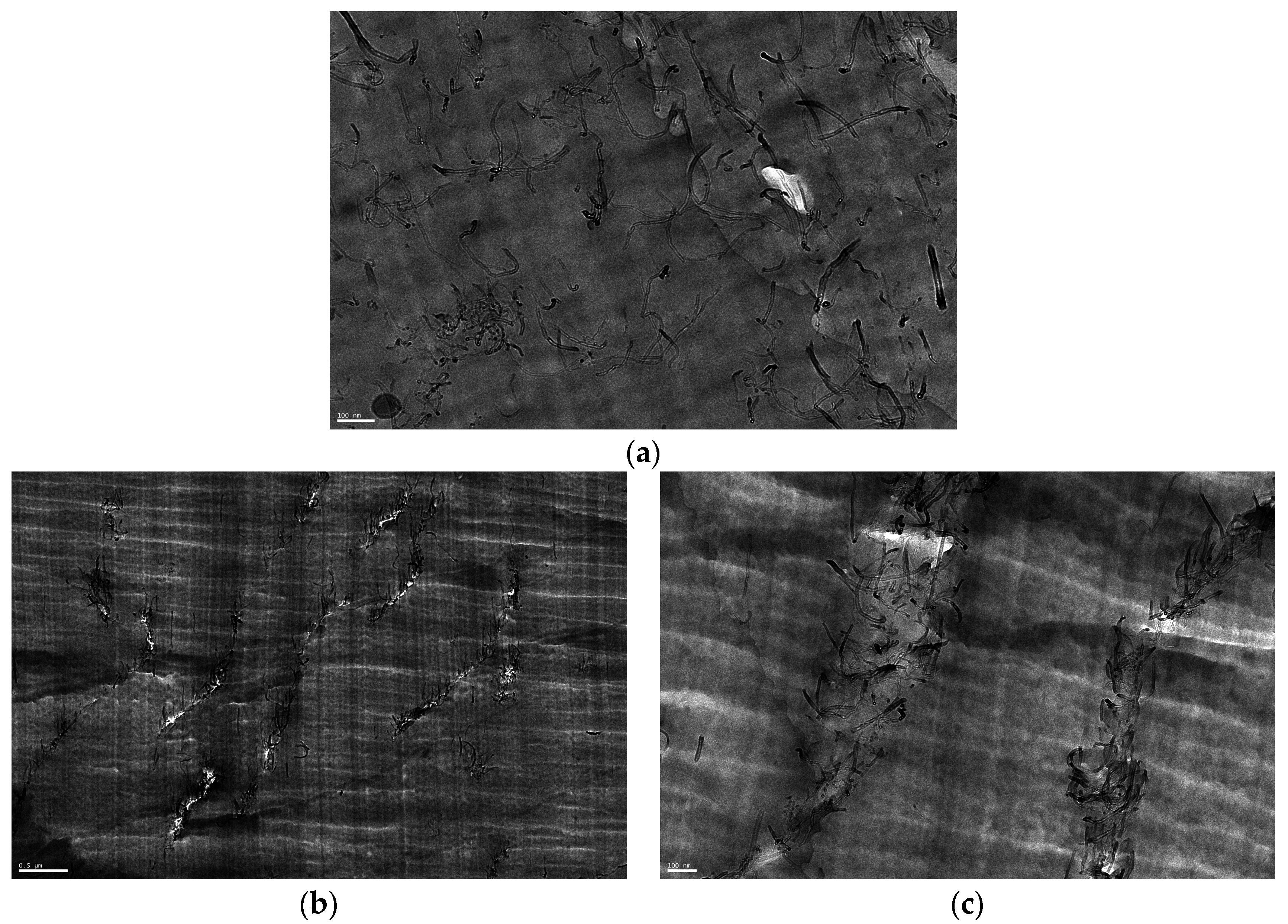
Figure 2.
Styrene-butadiene rubber (SBR) filled with a double filling (5 phr of CB + 5 phr of MWCNTs). Reprinted from Reference [35], with permission from John Wiley and Sons.
Figure 2.
Styrene-butadiene rubber (SBR) filled with a double filling (5 phr of CB + 5 phr of MWCNTs). Reprinted from Reference [35], with permission from John Wiley and Sons.

Figure 3.
Stress-strain curves of SBR (a) and NR (b) composites filled with MWCNTs and CB (in red).

Figure 4.
Mooney-Rivlin plots for SBR (a) and NR (b) composites filled with MWCNTs and CB (in red). For purpose of clarity, only two composites are reported in (a).
Figure 4.
Mooney-Rivlin plots for SBR (a) and NR (b) composites filled with MWCNTs and CB (in red). For purpose of clarity, only two composites are reported in (a).

Figure 5.
Tensile tests for neat NR and NR filled with 1 and 4 wt % FGS, and 16 wt % CB (a). 2D SAXS patterns (b) and ratio of the intensity at the equator (I90°) to the intensity at the meridian (I0°) versus strain determined from SAXS measurements for SBR and NR filled with FGS and CB (c). The inset represents the stretching and retraction data for 4 wt % FGS-filled SBR and NR. Reprinted from reference [54] with permission from The Journal of Polymer Science.

Figure 6.
Double logarithmic plot of the excess tensile modulus, with respect to neat polymer, as a function of CNT volume fraction for MWCNT/polyisoprene composites. Reprinted from reference [37], with permission from Macromolecular Materials and Engineering.
Figure 6.
Double logarithmic plot of the excess tensile modulus, with respect to neat polymer, as a function of CNT volume fraction for MWCNT/polyisoprene composites. Reprinted from reference [37], with permission from Macromolecular Materials and Engineering.

Figure 7.
Stress-strain curves of nitrile-butadiene rubber (NBR) filled with different expanded graphite (EG) amounts (a) and comparison of reinforcement efficiency of different fillers at a same loading (10 phr) (b). Reprinted reference [60], with permission from Acta Materialia.
Figure 7.
Stress-strain curves of nitrile-butadiene rubber (NBR) filled with different expanded graphite (EG) amounts (a) and comparison of reinforcement efficiency of different fillers at a same loading (10 phr) (b). Reprinted reference [60], with permission from Acta Materialia.

Figure 8.
Stress-strain responses of a 40 phr silica-filled poly(dimethylsiloxane) submitted to four cycles at various deformations, represented by different colors.
Figure 8.
Stress-strain responses of a 40 phr silica-filled poly(dimethylsiloxane) submitted to four cycles at various deformations, represented by different colors.
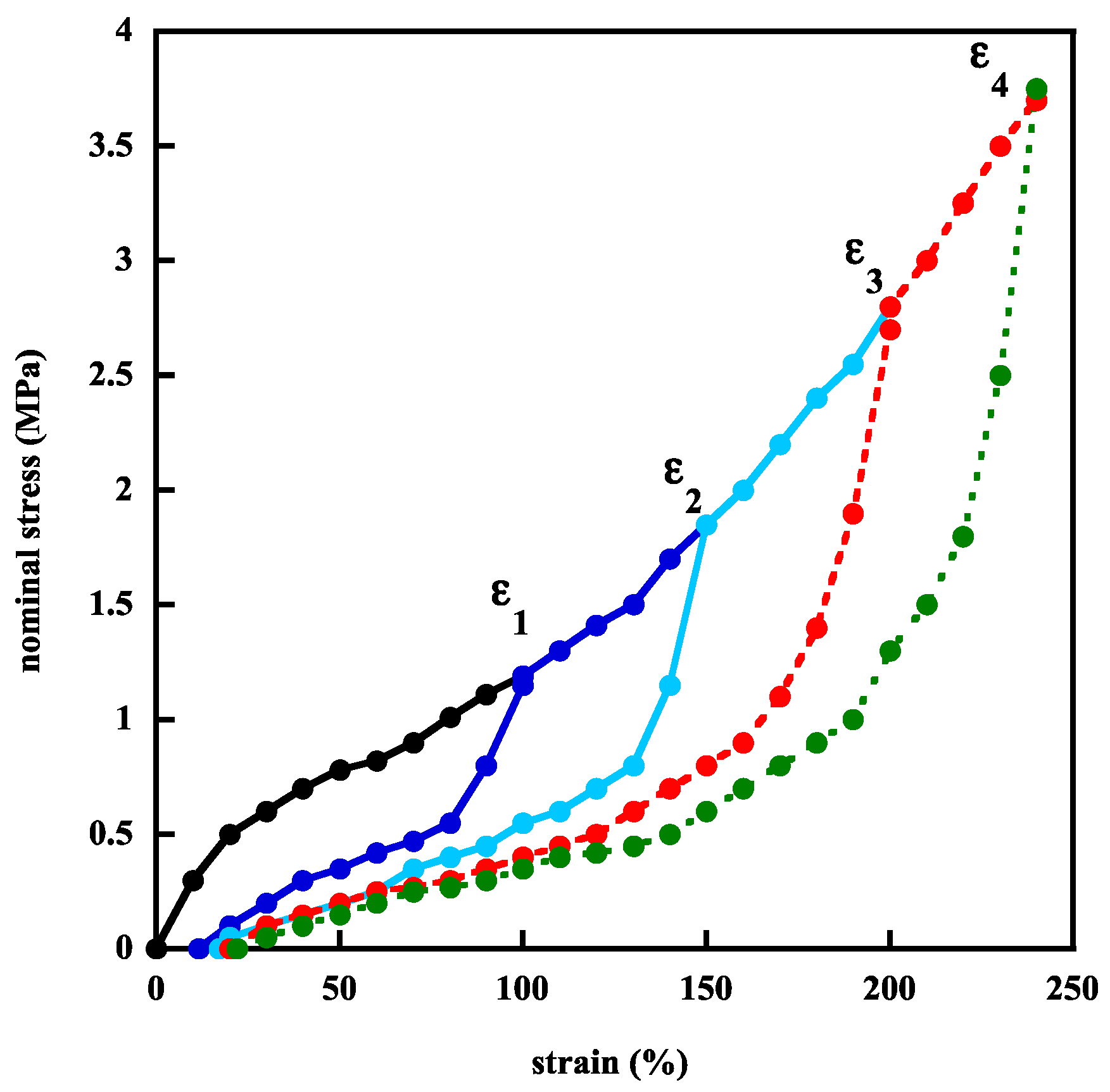
Figure 9.
Continuous (dashed lines) and cyclic stress-strain responses of EPDM filled with 50 phr of carbon black (a) and Estane (ether based polyurethane elastomer) with 5 wt % MWCNTs (b). Reprinted from reference [81].
Figure 9.
Continuous (dashed lines) and cyclic stress-strain responses of EPDM filled with 50 phr of carbon black (a) and Estane (ether based polyurethane elastomer) with 5 wt % MWCNTs (b). Reprinted from reference [81].

Figure 10.
Strain dependence of the storage modulus of PDMS filled with various amounts of silica particles generated in situ by the sol-gel process.
Figure 10.
Strain dependence of the storage modulus of PDMS filled with various amounts of silica particles generated in situ by the sol-gel process.
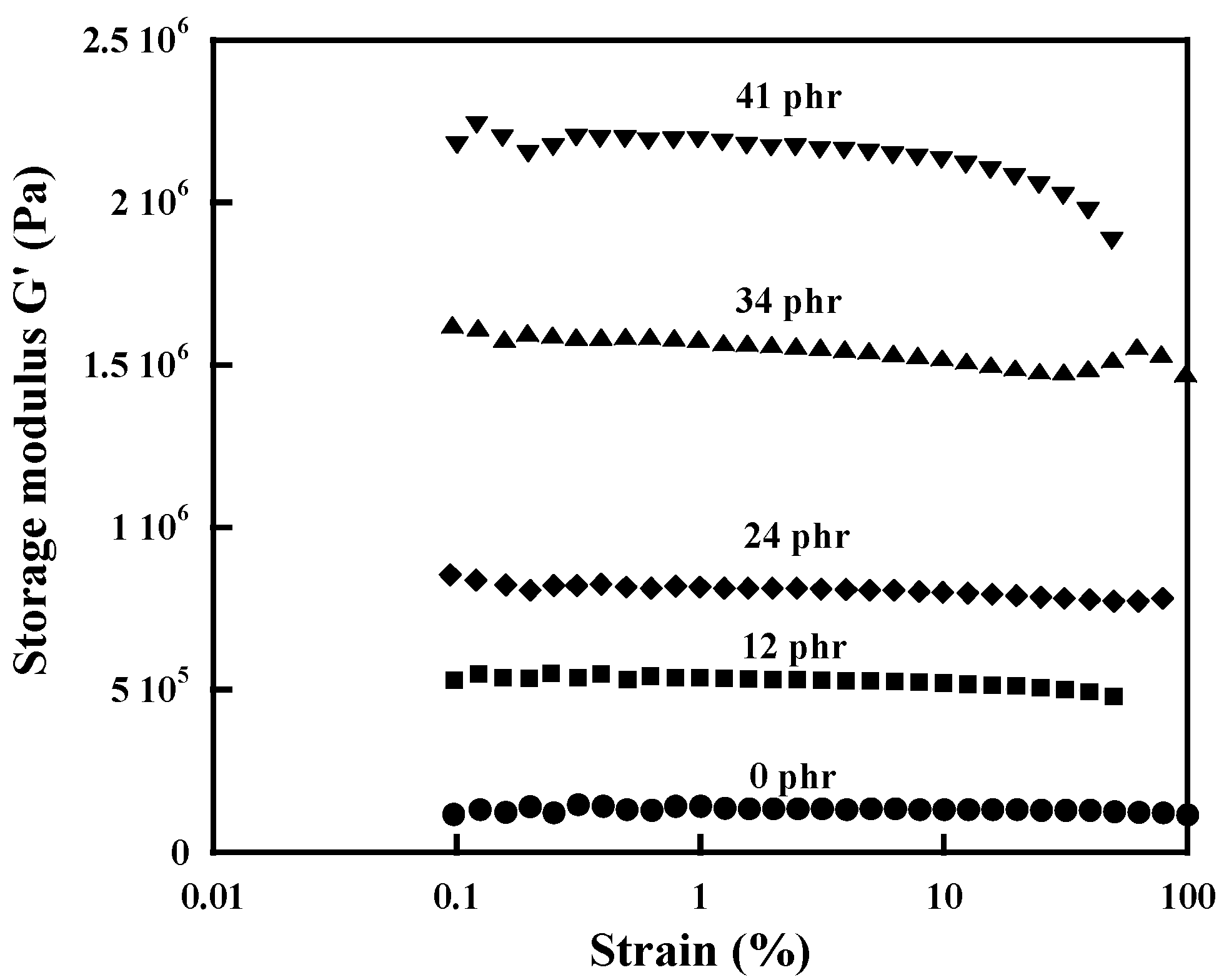
Figure 11.
Strain dependence of the storage modulus: at 25 °C of NR composites filled with CB and MWCNTs (a); at 25 °C of NR composites filled with CNTs (5 phr) and with reduced graphene oxide (2.5 phr) (CG600 and CG200) along with CNTs (2.5 phr) (b). Reprinted from reference [91], with permission from Soft Matter.

Figure 12.
Temperature dependence of the storage modulus and tan δ of: (a) unfilled SBR and composites filled with MWCNTs at different contents; (b) unfilled NR and composites filled with 4 wt % FGS and 16 wt % CB. (a) Reprinted from reference [93] with permission from KGK; (b) Reprinted from reference [54], with permission from The Journal of Polymer Science.

Figure 13.
Srain dependence of the electrical resistivity for natural rubber filled with 3 phr of MWCNTs. Labels in red: resistivity during the retraction process. The other colors represent the different loading cycles.
Figure 13.
Srain dependence of the electrical resistivity for natural rubber filled with 3 phr of MWCNTs. Labels in red: resistivity during the retraction process. The other colors represent the different loading cycles.

© 2017 by the authors. Licensee MDPI, Basel, Switzerland. This article is an open access article distributed under the terms and conditions of the Creative Commons Attribution (CC BY) license (http://creativecommons.org/licenses/by/4.0/).
Share and Cite
MDPI and ACS Style
Bokobza, L. Mechanical and Electrical Properties of Elastomer Nanocomposites Based on Different Carbon Nanomaterials. C 2017, 3, 10. https://doi.org/10.3390/c3020010
AMA Style
Bokobza L. Mechanical and Electrical Properties of Elastomer Nanocomposites Based on Different Carbon Nanomaterials. C. 2017; 3(2):10. https://doi.org/10.3390/c3020010
Chicago/Turabian StyleBokobza, Liliane. 2017. "Mechanical and Electrical Properties of Elastomer Nanocomposites Based on Different Carbon Nanomaterials" C 3, no. 2: 10. https://doi.org/10.3390/c3020010
Note that from the first issue of 2016, this journal uses article numbers instead of page numbers. See further details here.