Meltblown Solvated Mesophase Pitch-Based Carbon Fibers: Fiber Evolution and Characteristics


University of Tennessee Space Institute, 411 B.H. Goethert Parkway, Tullahoma, TN 37388, USA
*
Authors to whom correspondence should be addressed.
C 2017, 3(3), 26; https://doi.org/10.3390/c3030026
Submission received: 12 July 2017
/
Revised: 26 July 2017
/
Accepted: 7 August 2017
/
Published: 8 August 2017
(This article belongs to the Special Issue Carbon Fiber)
Abstract
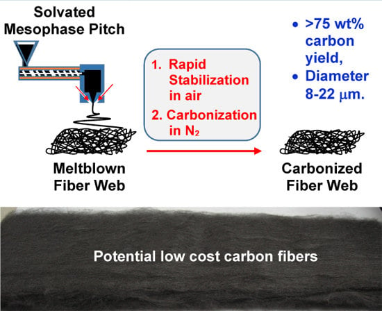
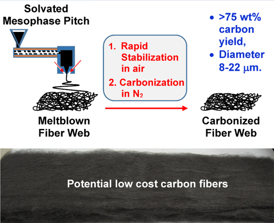
:Potentially low-cost continuous carbon fibers are produced from solvated mesophase pitch through a patented meltblowing process. The structural evolution and properties of the fibers are characterized by various analytical methods. The meltblown fibers are continuous fibers which are collected into a fibrous web form, and the diameter of the filaments is attenuated by the flow rate of air streams. The spun fibers can be rapidly stabilized in air due to the high melting mesogens and the removable solvent. The carbonized fibers show a high carbon yield of 75 wt % (or 86 wt % if the solvents are neglected) and a mean diameter of 8–22 μm with typical fiber diameter distribution and variation. The evolution of the fiber structure depends not only on the processing temperature but also on the fiber diameter. The processed carbon fibers retain the same form as the spun fibers and have a low packing density and reasonable mechanical properties.
1. Introduction
Carbon fibers (CFs) as a reinforcement in composite materials have been widely used in industry mainly due to their high specific strength and modulus. The large scale use of CFs in aircraft and aerospace is driven by maximum performance and fuel efficiency, while the cost factor and the production requirements are not critical. The use of CFs in general engineering and surface transportation is dominated by cost constraints, high production rate requirements, and generally less critical performance needs [1]. Therefore, the large-volume application of commercial CFs in the automotive industry has been hindered due to the high fiber costs and the lack of high-speed composite fabrication techniques [2]. It is believed that the use of low cost precursors, low cost spinning and thermal processes, and mass production is a critical step toward lower cost CFs and their composites for use in multiple industries [2,3,4].
Polyacrylonitrile (PAN) and conventional mesophase pitch (MP) are the two most important CF precursors for the manufacture of commercial CFs. Over the past two decades, many polymers, such as PE and lignin, have been evaluated as low-cost CF precursor materials. A significant amount of work has been done on engineering new precursors and processing technologies, relating fiber structure to properties, and translating the relationship into production for either reducing production cost [2,5,6] or increasing fiber properties [7,8,9]. Potentially low-cost CF has been produced from solvated MP pitch using a highly efficient meltblowing process [10]. Unlike conventional MP, solvated MP normally contains at least 70% by volume optical anisotropy, or MP in which at least 50 wt % is MP soluble quinoline insoluble (MSQI) pitch [11,12]. Due to its high MSQI content and adequate utilization of high melting mesogen materials, such an MP is of relatively lower cost. The added solvents make the pitch materials more spinnable at lower temperatures. When the solvent is removed, it has a high melting point, or may be unmeltable, which permits the formation of fibers that require little or no stabilization as spun [11,12,13]. It is well known that the meltblowing process is widely used to produce economical nonwoven fiber web. Similarly to the spun-bond process, the melt-blown process directly transforms the spun fibers into a nonwoven fabric in a single, integrated process [14]. Therefore, the use of solvated MP and meltblow technology would help to prepare low-cost CFs.
Most of the previous studies of pitch-based CFs have been conducted by using conventional MP and melt-spinning processes [15,16,17,18,19,20,21,22]. Very few studies focused on the newly developed, highly efficient meltblowing process of lower-cost solvated MP. It was reported that short CF was prepared from naphthalene MP through the meltblowing process [23]. However the short fibers will reduce their reinforcement in the composites and limit their application.
In the present study, low-cost, continuous CFs were prepared from solvated MP by using a patented meltblown fiber spinning technique [24] and relatively fast thermal stabilization in air and carbonization in N2. The structure, evolution and properties of the fibers were then characterized with various analyses and compared with commercially available CFs. The results helped us to optimize the CF preparation process, to better understand the characteristics of the prepared CFs, and improve their uses in composite materials.
2. Results and Discussion
2.1. Characteristics of the Spun Fibers
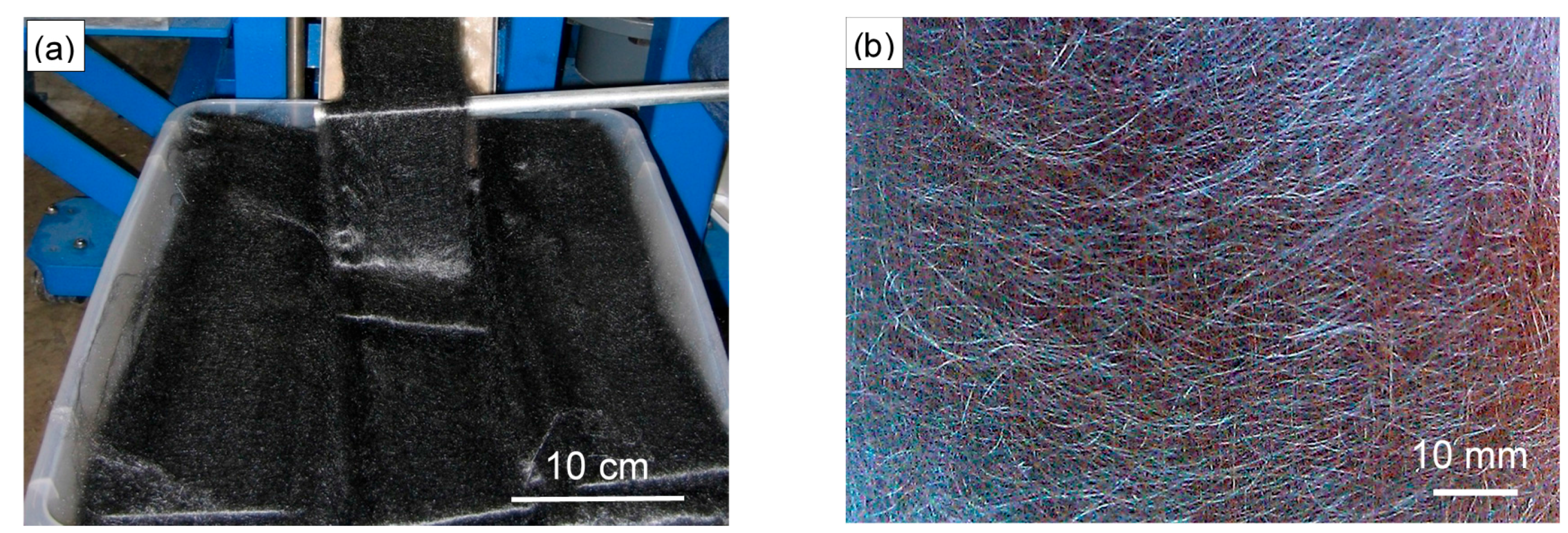
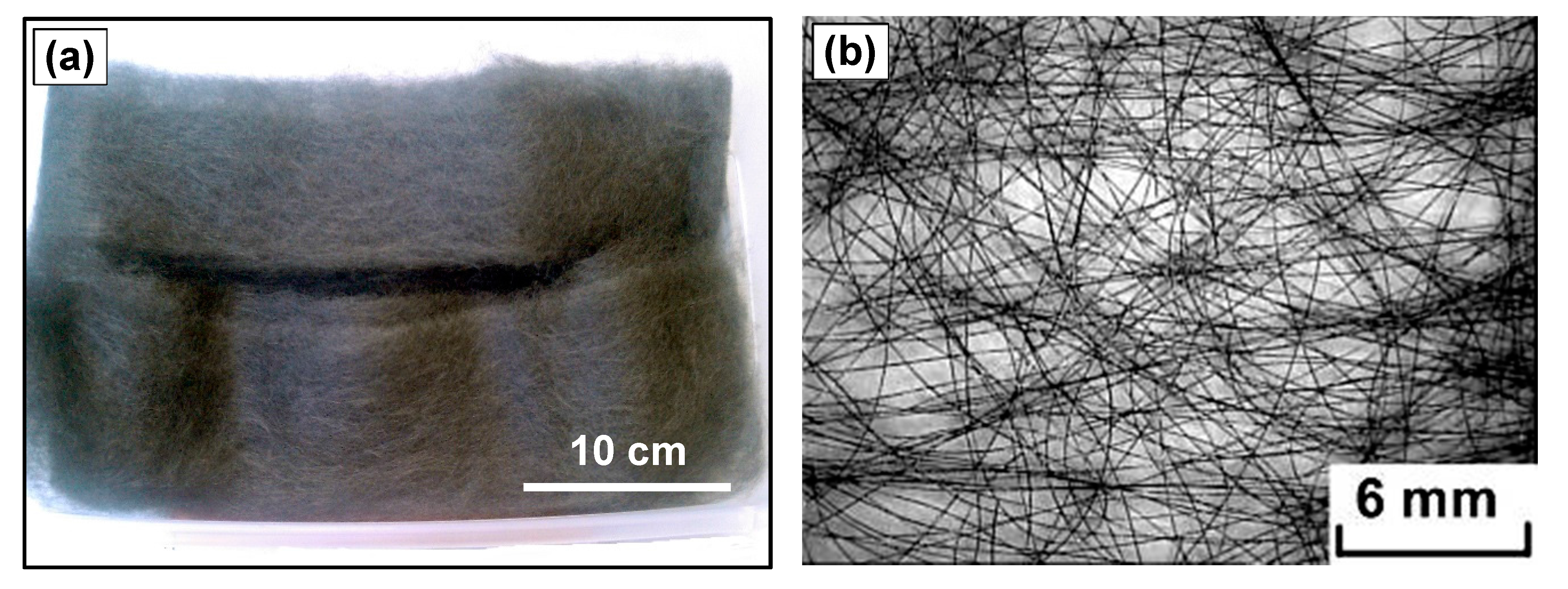
The solvated MP fibers (Figure 1) were continuously produced in the meltblown fiber spinning apparatus. The meltblown fibers were collected as shown in Figure 1a, and are continuous long fiber webs with a width and a thickness of approximately 10 cm and 1 cm, respectively. In the web of fibers, individual filaments are continuous fibers and are loosely assembled together, their orientation is controlled if needed, here only slightly toward the length of the web, as shown in Figure 1b. The rate of spinning, compared to the rate of collection of the fibers in a nonvowen web format, determines the orientation of the fibers in the web. The spun fibers are very brittle and need to be very carefully handled when transported.
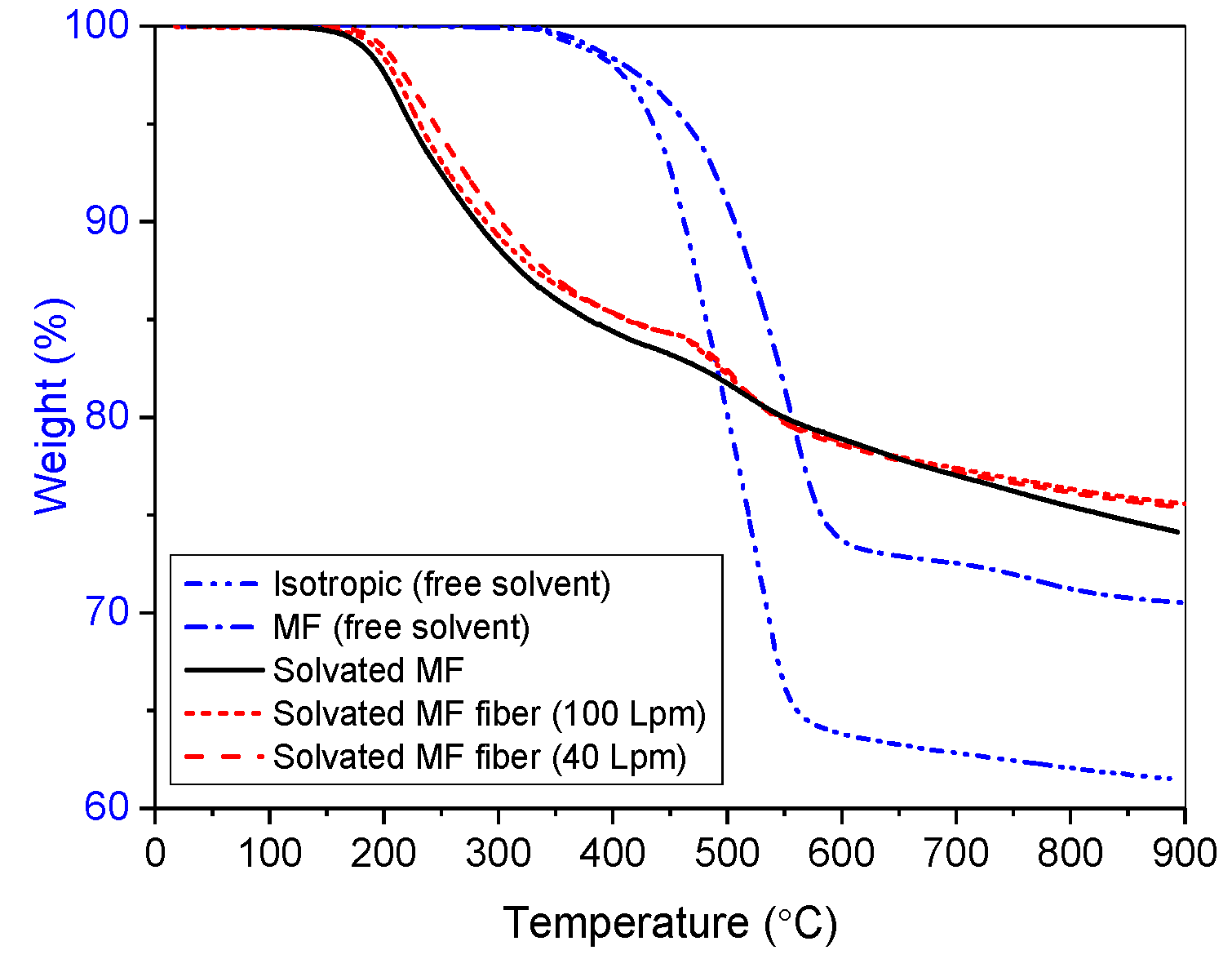
Due to the use of a solvated MP precursor, the spun fibers contained solvent. A thermogravimetric analysis (TGA) running in N2 was performed to compare the spun fibers (spun with a hot air flow rate of 40 and 100 L per minute (Lpm), respectively) with their precursor (solvated MP) and the conventional isotropic and MP materials (both solvent free). The results of the TGA are shown in Figure 2. Without solvents, both isotropic and MP materials showed a relatively high weight-loss starting point (335 °C). In contrast, the solvated MP and its fibers showed a relatively low weight-loss starting point (175 °C) due to the solvent removal. Based on the TGA results, the solvated MP and its fiber contained 12–16 wt % solvent. The solvent content of the spun fibers was less than 1% of its precursor, indicating that only a small amount of solvents was removed during the spinning process. Although the solvated MP and fibers contained a certain amount solvent, their carbon yields at 900 °C were still higher than that of the isotropic and MP (solvent free) materials. The apparent reason is that the solvated MP contains MSQI pitch and adequately utilizes high melting mesogen materials [11,12].
Due to the use of the meltblowing process involving attenuation via air streams, the diameter of the spun fibers can be attenuated by the flow rate of air streams. During the meltblowing process, the primary gas is used to keep the fiber centered and reduce the diameter of the resulting filament as it cools and solidifies after exiting the spinneret. The secondary gas is used to further entrain, apply and maintain tension on the filaments as the air flow conveys the filaments downward. The fibers spun from solvated MP have a very rapid quenching rate and solidify within a short distance of the spinneret exit [11,12]. Thus, for a given spinneret head, the diameter of the spun fibers mainly varies with the flow rate of the primary gas.
Since the spun fibers are very brittle and not feasible to handle mechanically for testing, the stabilized fibers were used to test and determine the relationship between the fiber diameter and the flow rate of the air streams, because it was found that the applied thermal processing does not seem to change the mean diameter from the spun fiber to the stabilized fibers. Figure 3 shows the fiber diameter and its standard deviation measured by optical microscopy analysis on the traverse section of fiber bundle-embedded samples. Within a given flow rate range (40–100 Lpm), the diameter of the stabilized fibers decreases as the flow rate of primary gas increases. Typically, all fiber diameters show a high standard deviation, indicating that the meltblown fibers have poor dimensional uniformity and need to be improved. It is believed that this is due to local turbulence and can be improved by higher quality design of the flow stream passages.
It was also found that the high flow rates resulted in fibers having a relatively small diameter and more waves, potentially due to higher stream turbulence. In contrast, the low flow rate allowed the fibers to have a relatively large diameter but to be straighter. Therefore, the next step was to explore the relationship between waves and air flow rate and to try to eliminate the fibers’ wave. This could also be achieved in future studies by applying tension to the fibers during thermal processes.
2.2. Stabilization and Carbonization of the Spun Fibers
Since the spun fibers contain high melting mesogens, they can be rapidly stabilized in air. Stabilization in air is considered to be the most economical process in the commercial manufacturing of CFs [25]. A typical stabilization condition used in this study allowed the fiber to be heated to 350 °C at a heating rate of 20 °C/min in air while maintaining the fiber form. The heating rate of 20 °C/min is much higher than the reported values of 0.1–2 °C/min in the literature [15,16,17,18,19,20]. After stabilization at 350 °C for 60 min, the stabilized fibers showed a fiber mass yield of 96–97% as shown in Figure 3. This 3–4% weight loss is much lower than 13 wt % solvent content in the spun fibers, indicating that stabilization of solvated MP fibers is unusual.
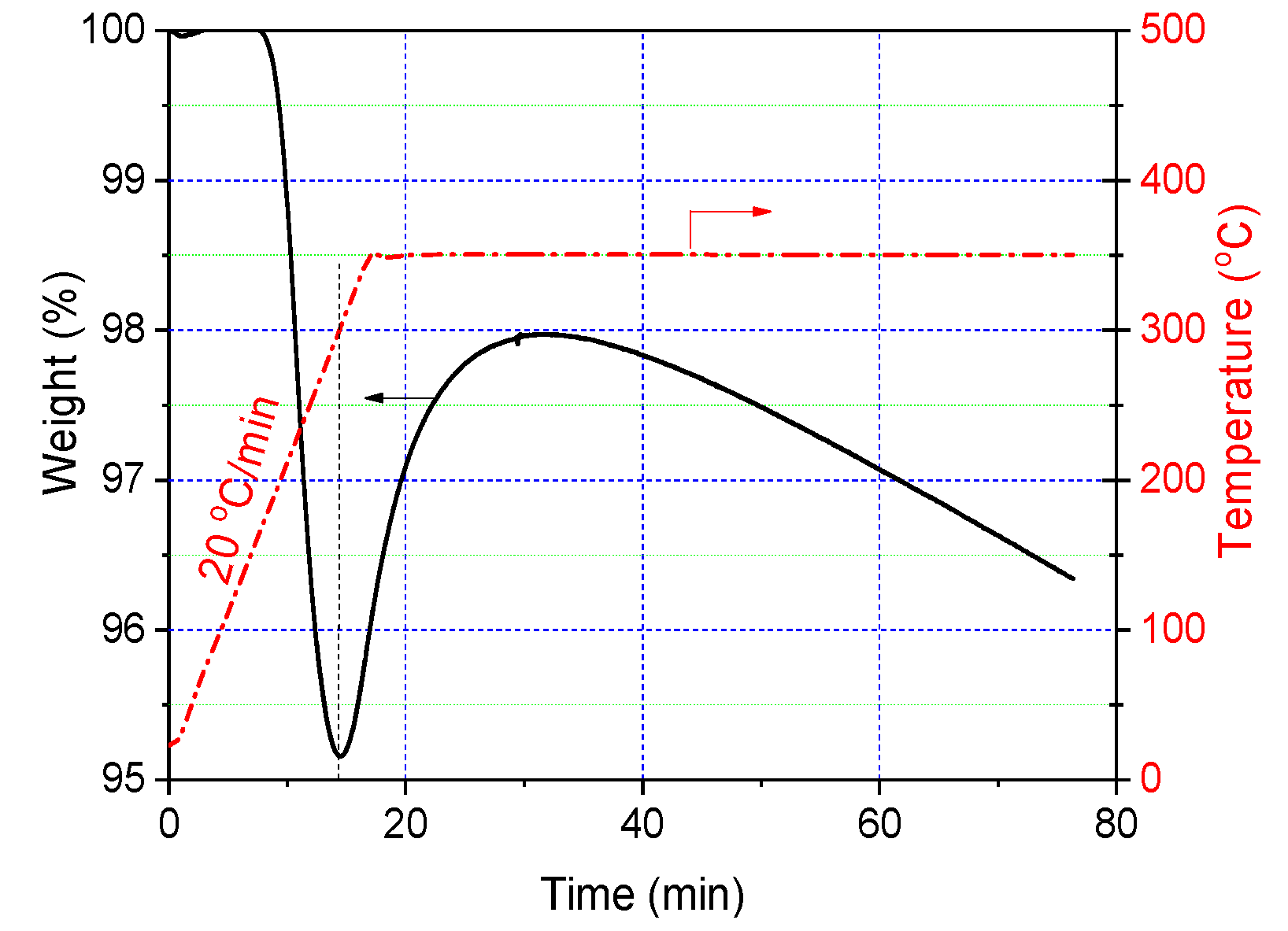
To study the thermal behavior of the spun fiber during stabilization, the same stabilization conditions described above were used for TGA analysis (Figure 4). As the stabilization temperature increased, the spun fiber began to lose weight at 175 °C due to solvent removal and reached maximum weight loss at 300 °C. After that, the fiber gained weight (this may start at 180 °C [26]) due to oxidation (oxygen is introduced into the fiber [26,27,28]). The maximum weight gain was observed at 350 °C at 15 min, and then the weight loss dominated the rest process again. These results suggest that, (I) the solvated MP fiber loses its weight (solvents) and meanwhile gains weight (oxygen) in the temperature range between 150 and 350 °C; and (II) at lower stabilization temperatures, weight loss dominates the thermal process as the rate of oxygen uptake is lower than the rate of solvent removal. Since the spun fiber loses solvent and also gains oxygen during stabilization, the stabilized fiber in TGA presents a total weight loss of 4% after stabilization at 350 °C for 60 min.
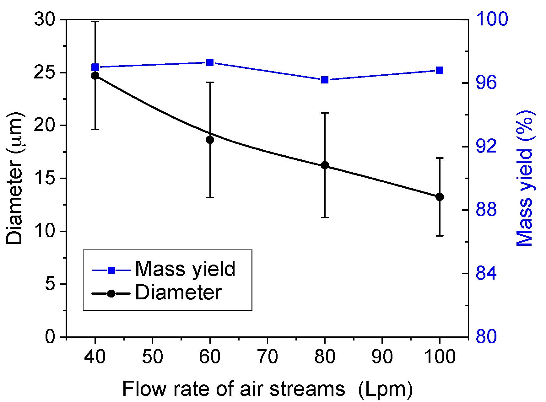
Four stabilized fibers meltblown with four different air flow rates (40, 60, 80, and 100 Lpm) were then carbonized in N2 under the same conditions in a tube furnace. The mass yield and mean diameter of fibers after carbonization at 1050 °C are shown in Figure 5. Based on the original weight of the spun fibers, carbonized fibers showed a 75 wt % yield. Disregarding the 13 wt % solvents in the spun fibers, the carbon yield of the resulting CFs is 86 wt %. The high carbon yield will undoubtedly benefit the manufacturing of this low-cost CF.
As compared with the diameter of the stabilized fibers in Figure 3, the diameter of the carbonized fibers in Figure 5 is significantly reduced. CFs with a mean diameter of 8–22 μm were obtained in this study.
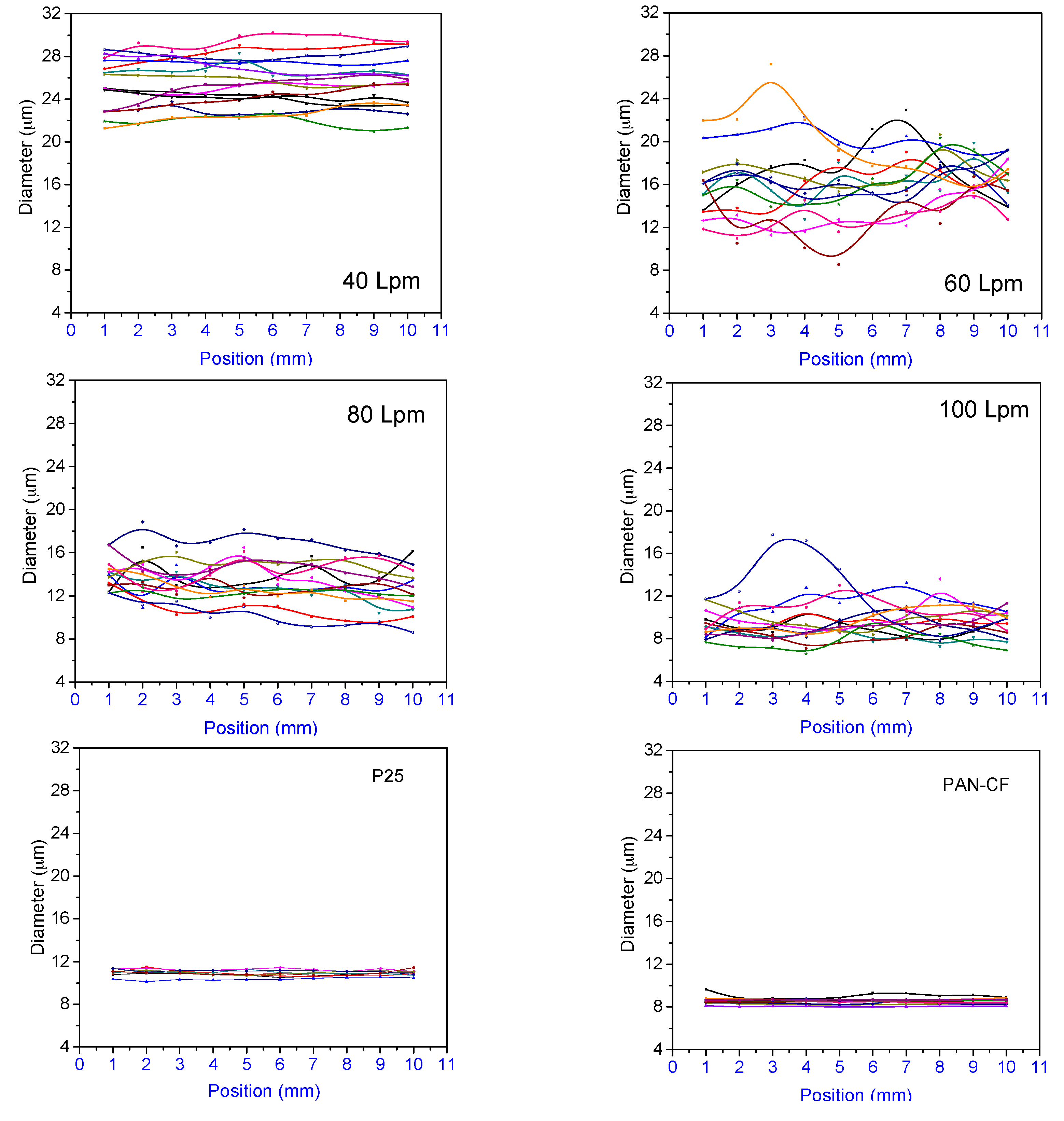
The fiber diameter variation along the fiber length within 10 mm and diameter distribution were examined with a laser scan micrometer. Typical results are shown in Figure 6 comparing four CFs prepared from four different pitch fibers spun with flow rates at 40, 60, 80, and 100 Lpm, respectively, and two commercially available products, pitch-based P25 and PAN-based CFs. All processed CFs have a certain degree of fiber diameter distribution and variation along the fiber length. The fibers processed at the low flow rate of 40 Lpm appeared to vary less in diameter along the fiber axis when compared to the other CFs spun at higher flow rates.
For meltblown fibers, these changes in diameter compared to the data in the literature [29] are normal and are typical of the fiber diameter distribution and variation. However, when compared to two commercially available CFs, P25 and PAN-CF, the CFs processed by the meltblown method have a poorer fiber diameter uniformity in terms of the fiber diameter distribution and the diameter variation along the fiber length. In view of this, improving the uniformity of the spun fiber diameter will be one of the main goals of future research studies.
2.3. Structure Evolution
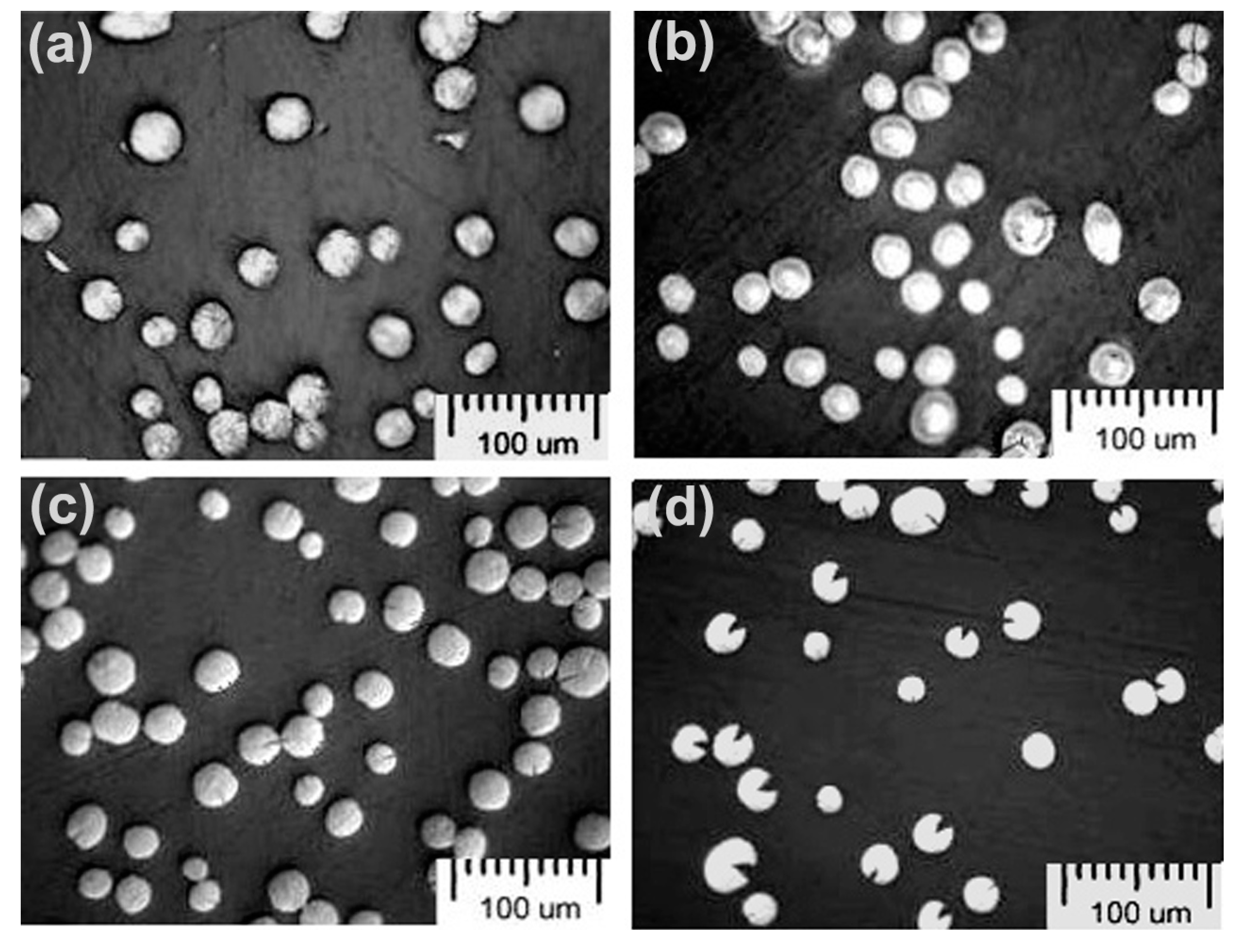
The morphological structure of the spun fibers, stabilized fibers and carbonized fibers at 600 °C and 1050 °C were examined using an optical microscope. Typical images of the fibers are shown in Figure 7. Figure 7a is a cross-sectional structure of the spun fibers. After stabilization, a sheath-core structure is observed in larger diameter (40 Lpm) fibers as shown in Figure 7b. However, no such a structure is found in smaller diameter (100 Lpm) fibers. The sheath is believed to be composed of well-stabilized, cross-linked, and relatively hard material while the core is composed of less-stabilized and relatively soft material [30]. The reason why the stabilized fibers exhibit the sheath–core structure can be interpreted as being that when the fiber embedded in epoxy resin was polished, the fiber cross-section could be a concave surface due to the different wear properties of the sheath and core materials. The concave center (core) surrounded by the edge (sheath) is the explanation for the two-phase structure observed under an optical microscope. This result suggests that the stabilization of the spun fiber is controlled by the diffusion of oxygen from the outside layer to the internal core [31]. Thus, the smaller diameter fiber is easier to stabilize uniformly, but the larger diameter fiber may stabilize gradually resulting in a sheath–core structure.
A radial crack structure or a “pac-man structure” [32] (fiber with wedge) as shown in Figure 7c,d is formed on the carbonized fibers during carbonization. It was found that the pac-man structure appears at 600 °C and become distinctly noticeable at 700 °C. From 800 °C onwards pac-man structures can be observed in almost all fibers with the angle of the pac-man mouth being the greatest at 1050 °C.
The crack formations in MP-based CFs have been studied [33,34,35,36,37,38] on melt-spun fibers. Previous papers have shown that the spinning conditions, such as the spinning temperatures, the Length/Depth of the nozzle dimension, the diameter and wall material of the spinning nozzle, and the type of MP influence the crack formation [31,32,33,34,35,36,37]. The alignment of the discotic mesophase molecules in the radial direction results in the material being fairly weak in the hoop direction, and the hoop stresses generated during the heat treatment are relieved by the Pac-man split [18]. The strong radial orientation causes weak interplanar bonding leading to ‘‘pac-man’’ splitting during heat treatment as the fiber densifies [38]. However, for the meltblown solvated MP fibers involved in this study, it was found that the larger diameter of fibers or the sheath–core structure formed in the stabilized fibers could also lead to the formation of a pac-man structure in the resulting CFs.
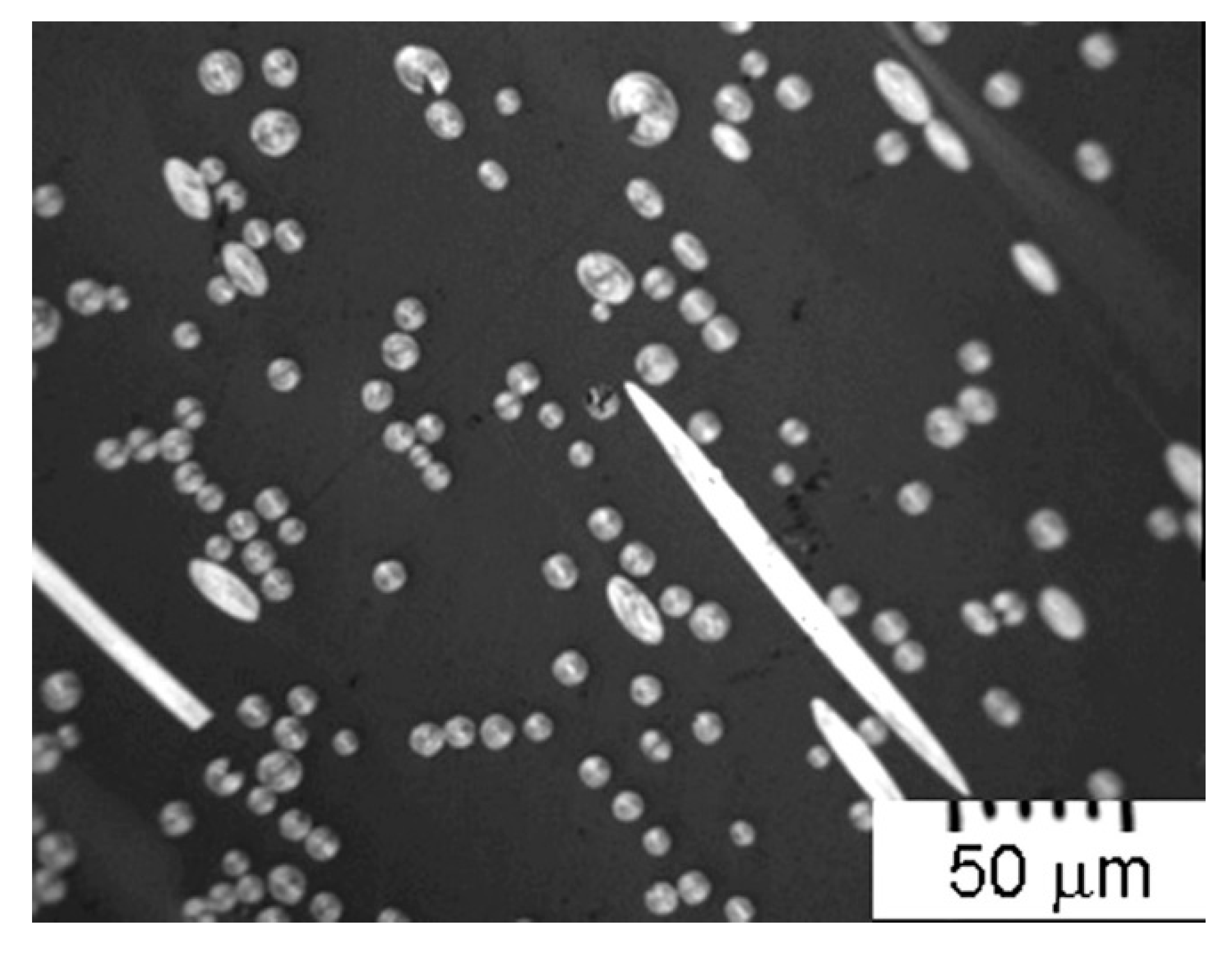
For smaller diameter fibers, the sheath–core structure was not observed on the stabilized fibers. As a result, the pac-man structure was not observed in the resulting CFs. A typical optical microscopy image of the CFs made from small-diameter pitch fiber (100 Lpm) is shown in Figure 8. There is no pac-man structure in most of the smaller diameter CFs, but such a structure still exists in several individual larger diameter fibers. When viewed with polarized light, optically anisotropic graphitic-crystallites with different orientations on a single fiber cross-section were detected by rotating the polarized lenses.
Typical images of pac-man structures under polarized light microscopy are shown in Figure 9. The processed CF has a heterogeneous microstructure which contains a pac-man crack, a radial transverse microstructure of the core, and a thin layer of skin.
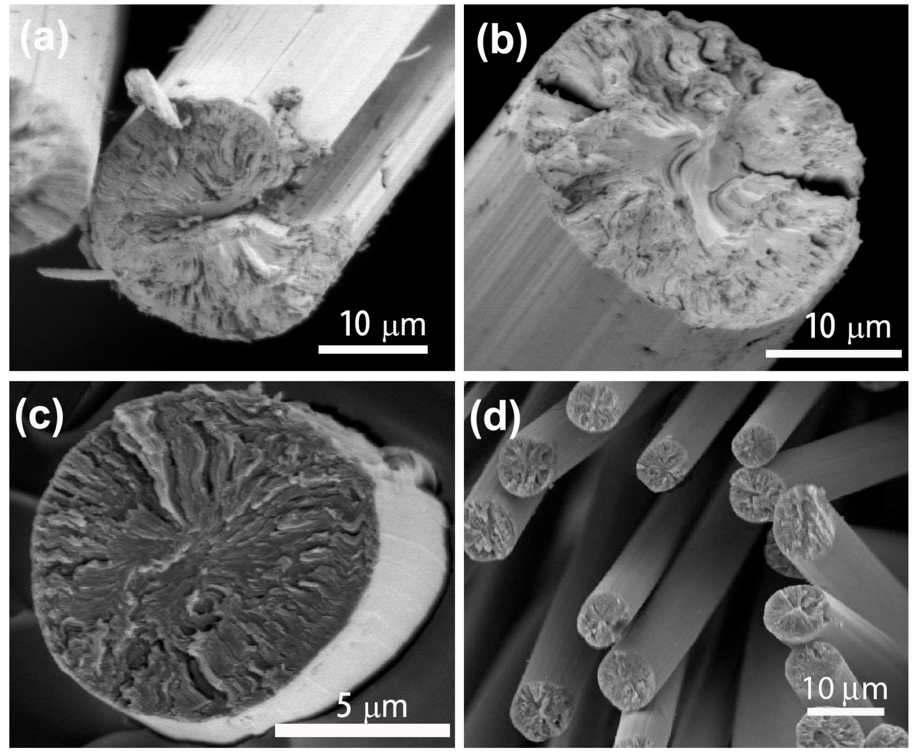
Scanning electron microscopy (SEM) images displays the pac-man cracks which developed along the fiber axis as shown in Figure 10a,b. The images also confirm the appearance of a radial transverse microstructure on the fiber cross-section. It is evident that less pac-man cracks formed in smaller diameter CFs, as shown in Figure 10c,d.
The fiber microcrystalline structures were also characterized with an X-ray diffractometer as shown in Figure 11. The spun fiber and the resulting CF display similar diffraction patterns, but the CF has a relatively sharp (002) main peak which poses a higher 2θ angle position and a narrower full width at half maximum (FWHM). According to Bragg’s law and Scherer’s equation, used in carbon research [39,40], the microcrystalline size (Lc) of the fiber increases and the d-spacing (d002) decreases as the MP fiber is converted into CF.
2.4. Characteristics of Carbonized Fibers
The processed CFs retain the same form of fiber web as the spun fibers. The typical CF form looks like a non-woven web as shown in Figure 12a. The fiber webs are continuously long. The filaments are continuous fibers and somewhat curved (Figure 12b). As compared with commercially available tow fibers, this fiber form has a much lower packing density at 0.012 g/cm3. It is noteworthy to mention that the processed CFs with this fiber form are effectively treated with O3 gas to improve their surface chemistry and can be directly used to fabricate CF composites without weaving and knitting [41].
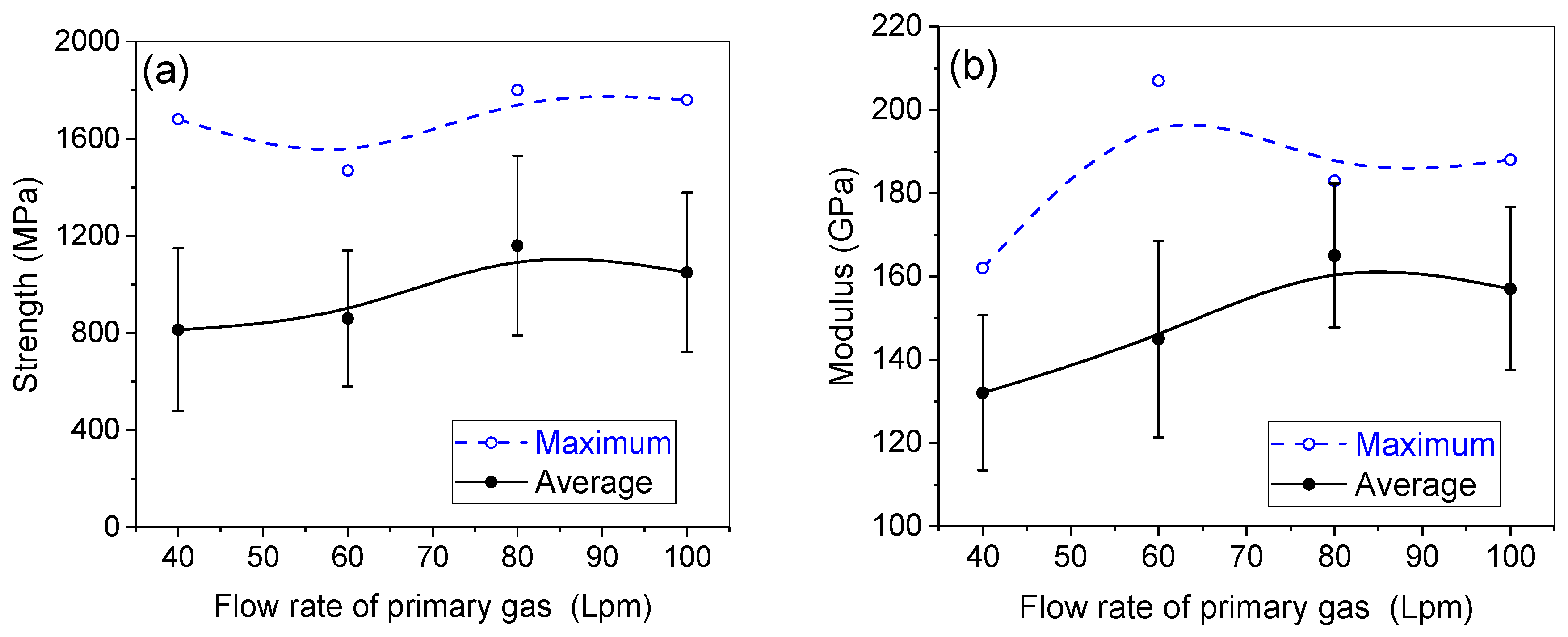
The tensile properties of the CFs processed at a carbonization temperature of 1050 °C are shown in Figure 13 as a function of the flow rate of air streams. As seen in Figure 13, the average strength and modulus of the fiber (8–22 μm) are 800–1200 MPa and 130–160 GPa, respectively. The maximum values can reach 1800 MPa and 200 GPa, respectively. All test values for the samples have a high deviation. The smaller diameter CFs associated with the higher flow rates of air streams exhibit higher average tensile strength and modulus. But the presence of high fiber waves caused by the high flow rate could reduce the tensile properties of the test results.
The tensile properties of CFs could depend on many factors including precursor materials and processes, such as fiber spinning, stabilization, and carbonization conditions. It is well-known that both the tensile strength and modulus of pitch-based CFs are strongly dependent on the carbonization temperature [42]. For the CFs prepared in this study, as the carbonization temperature went to 1500 °C, the average strength and modulus could be up to 2500 MPa and 200 GPa, respectively. A previous study has shown that by using separate drying and oxidation processes, the solvents in the spun fibers are first completely removed in N2, and then the dried fibers are oxidized in air. As a result, the tensile properties of the resulting CFs are remarkably improved [13]. Efforts are continuing toward optimizing the fabrication process to reduce defects in the fibers and improve the tensile properties of such low-cost CFs.
3. Materials and Methods
Solvated MP from ConocoPhillips Co. USA was employed as a starting material for spinning pitch fibers. In addition, conventional isotropic and MP materials (both solvent free) were used to compare with the solvated MP. As a comparison, commercially available pitch-based CF Thornel® P25, USA and PAN-based CF fabric (twill weave, ordered from Albany Engineered Composites, Rochester, NH, USA) were used for diameter measurement.
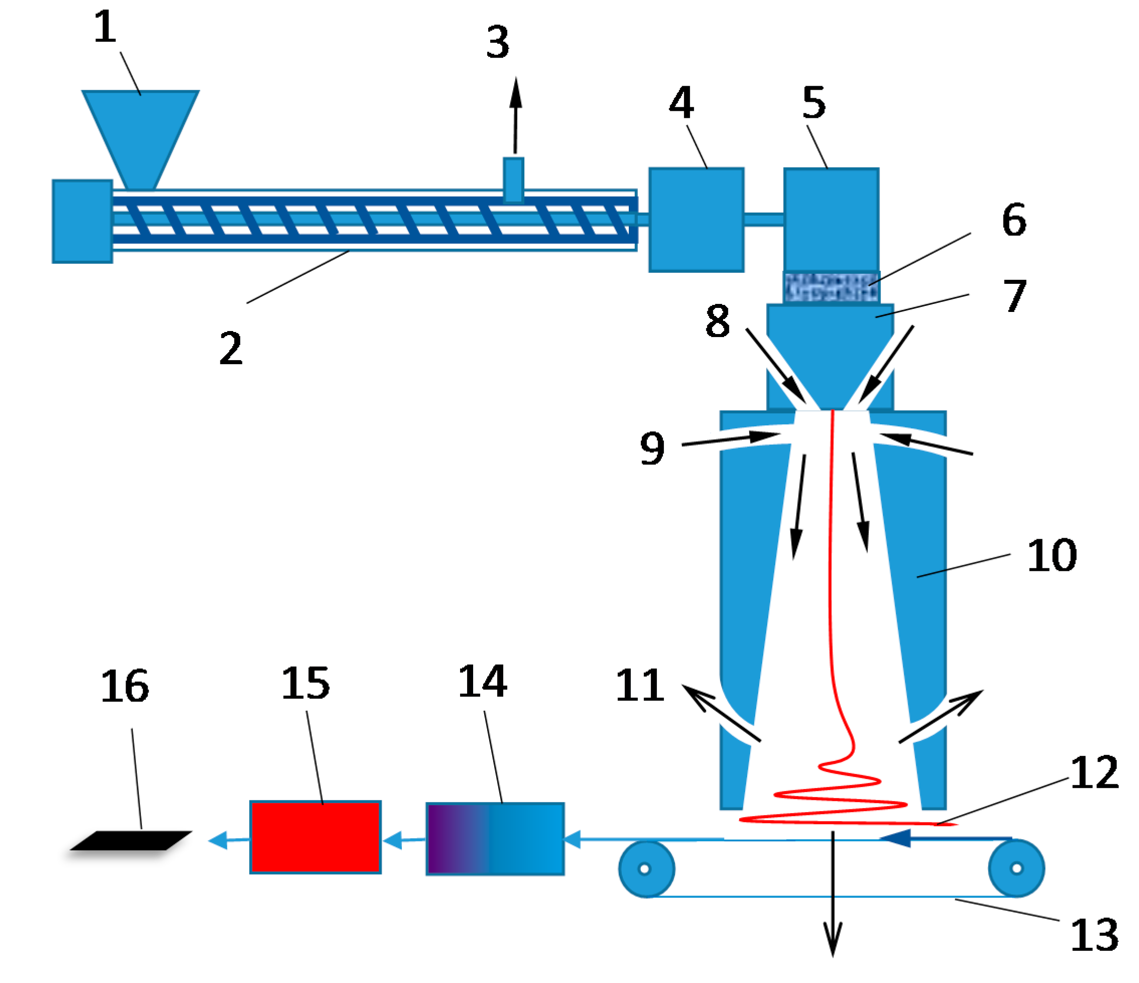
Solvated MP was spun into fibers in a meltblown device. The spinning system comprised a pitch feeding device, extruder, vacuum vent, ballast pump, spinning pump, filter, spinneret head, fiber collector, air flow jet regulator, and temperature and pressure, and vacuum control system, etc. as shown in Figure 14. The fibers were formed aerodynamically at speeds of several hundred meters per second and then slowed down to a few meters per second at the collection zone. The meltblown device comprised a spinneret head where exit orifices form filaments, a venturi adjacent to the spinnerets that receives the filaments from the spinneret head, a diffuser near the venture that receives the filaments from the venture, one or more air exhaust ports that creates in the diffuser an airflow with a direction against the direction of the flow of the filaments, and a fiber collection bed that receives the filaments in the form of a finite width continuous non-woven web [24].
In this study, the temperature of the spinneret head and primary air was set to 355 °C. The number of filaments produced was 10 (adjustable from 1 to 1000). Fibers were collected on a moving belt in a web format. Four pitch fibers with four different nominal diameters corresponding to air flow rates of 40, 60, 80, and 100 Lpm, respectively, were investigated.
The spun pitch fibers were stabilized in the flowing air by heating them at 20 °C/min in an oven from room temperature to 350 °C, and holding the temperature constant for 60 min. The stabilized fibers were then carbonized in a furnace purged with flowing N2, by heating them at 20 °C/min to a given temperature, and holding the selected temperature constant for 5 min. No tension was applied on fibers in the above thermal processes.
The fiber mass yield (%) was calculated from the measurements in weight changes prior to and after thermal treatments.
Thermogravimetric analysis, SDT Q600, TGA/DSC combo (TA Instruments, New Castle, DE, USA) was used to measure the weight changes in the pitch and its fiber during the stabilization and carbonization.
The tensile properties of CFs and fiber diameter variations were measured with a Diastron Limited FDAS 765 fiber analyzer (Dia-stron Limited, Andover, UK) that consisted of a high resolution tensile tester (LEX 810) with a force resolution of 0.005 gram and a Mitutoyo LSM-500 laser scan micrometer (Dia-stron Limited, Andover, UK) with a positional repeatability of 0.1 µm [43]. The filament was mounted on two plastic tabs with a distance of 10 mm by welding with jeweler’s wax, and placed on a tray. The tray held 15 filaments for tests. Usually 2–4 trays (30–60 filaments) were chosen from each sample for analysis. The laser micrometer secured the fiber in place for measurement of the cross-sectional area using a mechanized holder. The holder rotated and moved horizontally so that measurements could be taken along the length of fiber as well as at different points around the circumference of the fiber. Readings were taken along the length of the fiber at points referred to as “slices.” At each slice, the measurements of the cross-sectional area were taken around the fiber as it was rotated at 20 azimuthal angles, incrementally to 180°. The cross-sectional areas for each angle of each slice were then averaged to give the mean cross-sectional area of the fiber. In this study, 10 slices were scanned for each fiber with a length of 10 mm.
An optical microscope was used to examine the cross-sectional structure of the fibers. Fibers must be carefully prepared before they can be observed under the optical microscope. First, relatively straight portions of fibers were selected from a batch of fibers. Then this portion was cut out and wrapped with a short piece of clear vinyl tubing. Epoxy resin made with a 5:1 ratio of Epoxy 105 and Hardener 206 (West System, Bay City, MI, USA) was then injected into the tubing via a syringe. After the epoxy resin curing, the tubing was then peeled open to release the fiber/epoxy rod sample where fibers were embedded in the epoxy resin with high fiber volume and alignment. The prepared rod samples were then arranged in an orderly fashion and placed into an open cylinder tray where the axes of the samples were aligned with the axis of the cylinder. The same ratio of epoxy/hardener as the above was then also poured into the open cylinder to hold all the different samples in place. After fully curing, the clear epoxy piece was then taken out of the open cylinder and underwent polishing. Once the epoxy piece was polished then it was placed under an optical microscope for observation and imaging of the individual cross-sections of fiber bundles. The optical microscope Olympus® BX60M (Olympus Corporation, Tokyo, Japan) was used in conjunction with the camera Infinity 1 and software Infinity Analyze version 5.0.2 (Lumenera® Corporation, Nepean, Ottawa, ON, Canada) to capture images of the CF cross-sections [43].
The diameter of the stabilized fibers was analyzed with a freeware called ImageJ offered by the National Institute of Health, USA (https://imagej.nih.gov/ij/). Size selection and analysis were set as: size (pixel2) = 4-infinity, circularity = 0.85–1.00, exclude edges, and include holes. The number of filaments obtained from each image was about 20–200 depending on the fiber diameter, fiber volume, and fiber alignment in the embedded samples. Usually 2–4 images were analyzed for each sample. The pixels obtained from 130–400 individual fibers were then read for different cross-sectional areas and the average diameter and standard deviation of the fibers were calculated.
The morphological structure of CFs was examined with an SEM machine, SUPER-III A, International Scientific Instruments, Pleasanton, CA, USA. The image recorded was processed by the EDS 2004 version 1.3 Rev P (IXRF system, Austin, TX, USA). A thin layer of gold was coated on the fibers with a sputter coater to provide higher resolution images.
The microcrystalline structures of pitch fibers and CFs were characterized with an X-ray diffractometer, Philips X’Pert–MPD system, and Philips Analytical X-ray PW 1700 (Philips, Almelo, The Netherlands). The fiber sample was ground into a fine powder and then impregnated with vacuum grease to adhere it to a mold. The wavelengths of the X-rays emitted were 1.54 Angstroms. All samples were set to be scanned from 15 to 65 degrees with a scan rate at 0.01 degrees per two seconds.
4. Conclusions
With a patented meltblown high throughput fiber-spinning technique, solvated MP was spun into fibers at four different nominal diameters corresponding to air flow rates of 40, 60, 80, and 100 Lpm, respectively, and the continuous fibers were collected in a nonwoven fibrous web format. The meltblown fibers contained 13 wt % of solvents which was able to be removed by heating. Due to the high content of melting mesogens, the meltblown fiber was able to be rapidly (with a heating rate of 20 °C/min) stabilized in air. TGA results show that the meltblown fibers start to lose weight at 175 °C due to the solvent removal, and then gain weight at 300 °C due to the oxidation of pitch materials. As a result, the stabilized fibers only show 4 wt % weight loss. The carbonized fibers show a high carbon yield of 75 wt % (86 wt % if disregarding the solvents) after carbonization at 1050 °C.
The diameter of the meltblown fibers was primarily attenuated by the air flow rates in fiber meltblowing process and decreased as the air flow rates increased. The diameter did not change significantly after stabilization but reduced after carbonization. Thus, the processed CFs had an average diameter of 8 to 22 µm depending on the flow rate of air streams. High air flow rates formed a relatively small diameter and more waves. In contrast, low flow rates made the fibers have a relatively large diameter, but be straighter. Typically, the processed CFs had a certain degree of fiber diameter distribution and diameter variation along the fiber length.
A sheath–core structure was observed in the stabilized fibers of larger diameter. Such a structure was found to readily result in the formation of pac-man cracks in the resulting CFs. The pac-man cracks developed at 600°C and the cracks opened larger as the carbonization temperature increased. X-ray diffraction shows that the size of crystallites increased and d-spacing decreased as the MP was converted to CFs. The fiber form was different to that of the commercial CFs. It was a continuous non-woven web with a very low packing density of 0.012 g/cm3, and its filament was continuously long but somewhat curved. The fiber tensile properties were strongly influenced by the carbonization temperatures. At 1050 °C, the average tensile strength and modulus of the processed fibers (8–22 μm) were 800–1200 MPa and 130–160 GPa, respectively. At 1500 °C, they increased up to 2500 MPa and 200 GPa, respectively.
Acknowledgments
Sincere thanks to Advanced Research Labs and Technical Support at The University of Tennessee Space Institute: Jim Goodman, Joel Davenport, Kate Lansford, Douglas Warnberg, and Gary Payne for their timely technical and machining support and fabrication including numerous helpful discussions. In particular many thanks and appreciation is due to W. Mark Southard and Daniel F. Rossillon for their various tangible and intangible support and advice for systems developments, integration and expert suggestions and advice. The authors would like to thank Federal Transit Administration (FTA), U.S. Department of Transportation (DoT) for their support (contract No. TN-26-7029-00).
Author Contributions
Ahmad Vakili conceived the overall spinning idea and process concept, and carried out the fiber spinning process. Zhongren Yue designed the experiments and manuscript. Chang Liu and Zhongren Yue carried out the thermal processes and characterization experiments. All the authors have contributed to the writing of this article.
Conflicts of Interest
The authors declare no conflict of interest.
References
- Chand, S. Review Carbon fibers for composites. J. Mater. Sci. 2000, 35, 1303–1313. [Google Scholar] [CrossRef]
- Huang, X. Fabrication and properties of carbon fibers. Materials 2009, 2, 2369–2403. [Google Scholar] [CrossRef]
- Oak Ridge National Laboratory. Transportation Technology Program. Annual Report; 2008. Available online: https://energy.gov/sites/prod/files/2014/03/f8/ornl_ttp_report_fy08.pdf (accessed on 12 February 2017).
- Sullivan, R.A. Automotive carbon fiber: Opportunities and challenges. JOM 2006, 11, 77–79. [Google Scholar] [CrossRef]
- Hosseinaei, O.; Harper, D.P.; Bozell, J.J.; Rials, T.G. Role of physicochemical structure of organosolv hardwood and herbaceous lignins on carbon fiber performance. ACS Sustain. Chem. Eng. 2016, 4, 5785–5798. [Google Scholar] [CrossRef]
- Baker, D.A.; Rials, T.G. Recent advances in low-cost carbon fiber manufacture from lignin. J. Appl. Polym. Sci. 2013, 130, 713–728. [Google Scholar] [CrossRef]
- Khayyam, H.; Fakhrhoseini, S.M.; Church, J.S.; Milani, A.S.; Bab-Hadiashar, A.; Jazar, R.; Naebe, M. Predictive Modelling and Optimization of Carbon Fiber Mechanical Properties through High Temperature Furnace. Appl. Therm. Eng. 2017. Available online: http://dx.doi.org/10.1016/j.applthermaleng.2017.06.071 (accessed on 1 July 2017).
- Liu, J.; Yue, Z.; Fong, H. Continuous nanoscale carbon fibers with superior mechanical strength. Small 2009, 5, 536–542. [Google Scholar] [CrossRef] [PubMed]
- Chae, H.G.; Newcomb, B.A.; Gulgunje, P.V.; Liu, Y.; Gupta, K.K.; Kamath, M.G.; Lyons, K.M.; Ghoshal, S.; Pramanik, C.; Giannuzzi, L. High strength and high modulus carbon fibers. Carbon 2015, 93, 81–87. [Google Scholar] [CrossRef]
- Vakili, A.; Yue, Z.; Fei, Y.; Cochran, H.; Allen, L.; Duran, M. Pitch based carbon fiber processing and composites. In Proceedings of the SAMPE Fall Technical Conference (39th ISTC), Cincinnati, OH, USA, 29 October–1 November 2007. [Google Scholar]
- Walter, M.; Kalback, H.; Romine, E.; Bourrat, X.M. Solvated Mesophase Pitches. U.S. Patent 5,259,947, 9 November 1993. [Google Scholar]
- Southard, W.M.; Romine, H.E.; Nanni, E.J.; Carel, M.W. Process for Making Solvated Mesophase Pitch. U.S. Patent 5,437,780, 1 August 1995. [Google Scholar]
- Yue, Z.; Liu, C.; Vakili, A. Solvated mesophase pitch-based carbon fibers: Thermal-oxidative stabilization of the spun fiber. J. Mater. Sci. 2017, 52, 8176–8187. [Google Scholar] [CrossRef]
- Silva, E. The Melt-Blowing Process. Available online: https://www.academia.edu/440299/The_melt-blowing_process_-_Nonwovens (accessed on 21 July 2017).
- Mochida, I.; Ling, L.; Korai, Y. Some factors for the high performances of mesophase pitch based carbon fibre. J. Mater. Sci. 1994, 29, 3050–3056. [Google Scholar] [CrossRef]
- Tomioka, T.; Arai, Y.; Hamada, T. Pitch-based carbon fibres derived from thermoset fibres oxidized with Cl2 containing air. J. Mater. Sci. 1995, 30, 1570–1576. [Google Scholar] [CrossRef]
- Yao, Y.; Chen, J.; Liu, L.; Dong, Y.; Liu, A. Mesophase pitch-based carbon fiber spinning through a filter assembly and the microstructure evolution mechanism. J. Mater. Sci. 2014, 49, 191–198. [Google Scholar] [CrossRef]
- Ogale, A.A.; Lin, C.; Anderson, D.P.; Kearns, K.M. Orientation and dimensional changes in mesophase pitch-based carbon fibers. Carbon 2002, 40, 1309–1319. [Google Scholar] [CrossRef]
- Wazir, A.H.; Kakakhel, L. Preparation and characterization of pitch-based carbon fibers. New Carbon Mater. 2009, 24, 83–88. [Google Scholar] [CrossRef]
- Lu, S.; Blanco, C.; Rand, B. Large diameter carbon fibres from mesophase pitch. Carbon 2002, 40, 2109–2116. [Google Scholar] [CrossRef]
- Mora, E.; Blanco, C.; Santamarı́a, R.; Granda, M. A novel method to obtain a petroleum-derived mesophase pitch suitable as carbon fibre precursor. Carbon 2003, 41, 445–452. [Google Scholar] [CrossRef]
- MInus, M.; Kumar, S. The processing, properties, and structure of carbon fibers. JOM 2005, 57, 52–58. [Google Scholar] [CrossRef]
- Watanabe, F.; Korai, Y.; Mochida, I.; Nishimura, Y. Structure of melt-blown mesophase pitch-based carbon fiber. Carbon 2000, 38, 741–747. [Google Scholar] [CrossRef]
- Vakili, A.; Rossillon, D. Process for Collection of Continuous Fibers as a Uniform Batt. U.S. Patent 8,206,640, 26 June 2012. [Google Scholar]
- Morgan, P. Carbon Fibers and Their Composites; CRC Press: Boca Raton, FL, USA, 2005. [Google Scholar]
- Singer, L.S.; Mitchell, S. Diffusion of oxygen into pitch. Carbon 1997, 35, 599–604. [Google Scholar] [CrossRef]
- Matsumoto, T.; Mochida, I. A structural study on oxidative stabilization of MP pitch fibers derived from coal tar. Carbon 1992, 30, 1041–1046. [Google Scholar] [CrossRef]
- Lavin, J.G. Chemical reactions in the stabilization of mesophase pitch-based fibers. Carbon 1992, 30, 351–357. [Google Scholar] [CrossRef]
- Bresee, R.R.; Qureshi, U.A. Influence of process conditions on melt blown web structure. Part IV—Fiber diameter. J. Eng. Fibers Fabr. 2006, 1, 32–46. [Google Scholar]
- Otani, S. Mechanism of the carbonization of mesophase carbon fiber at the low temperature range. Carbon 1967, 5, 219–220. [Google Scholar] [CrossRef]
- Mochida, I.; Toshima, H.; Korai, Y.; Hino, T. Oxygen distribution in the mesophase pitch fiber after oxidative stabilization. J. Mater. Sci. 1989, 24, 389–394. [Google Scholar] [CrossRef]
- Gerald, J.D.F.; Pennock, G.M.; Taylor, G.H. Domain structure in MP (mesophase pitch)-based fibres. Carbon 1991, 29, 139–164. [Google Scholar] [CrossRef]
- Donnet, J.B.; Qin, R.Y. Study of carbon fiber surfaces by scanning tunnelling microscopy, part I. Carbon fibers from different precursors and after various heat treatment temperatures. Carbon 1992, 30, 787–796. [Google Scholar] [CrossRef]
- Yoon, S.H.; Takano, N.; Korai, Y.; Mochida, I. Crack formation in mesophase pitch based carbon fibers: Part I Some influential factors for crack formation. J. Mater. Sci. 1997, 32, 2753–2758. [Google Scholar] [CrossRef]
- Yoon, S.H.; Korai, Y.; Mochida, I. Crack formation in mesophase pitch based carbon fibres: Part II Detailed structure of pitch based carbon fibres with some types of open cracks. J. Mater. Sci. 1997, 32, 2759–2769. [Google Scholar] [CrossRef]
- Matsumoto, M.; Iwashita, T.; Arai, Y.; Tomioka, T. Effect of spinning conditions on structures of pitch-based carbon fiber. Carbon 1993, 31, 715–720. [Google Scholar] [CrossRef]
- Matsumoto, T. Mesophase pitch and its carbon fibers. Pure Appl. Chem. 1985, 57, 1553–1562. [Google Scholar] [CrossRef]
- Alway-Cooper, R.M.; Anderson, D.P.; Ogale, A.A. Carbon black modification of mesophase pitch-based carbon fibers. Carbon 2013, 59, 40–48. [Google Scholar] [CrossRef]
- Wang, P.H.; Liu, J.; Yue, Z.R.; Li, R.Y. Thermal oxidative stabilization of polyacrylonitrile precursor fiber—Progression of morphological structure and mechanical properties. Carbon 1992, 30, 113–120. [Google Scholar] [CrossRef]
- Shirvanimoghaddam, K.; Abolhasani, M.M.; Li, Q.; Khayyam, H.; Naebe, M. Cheetah skin structure: A new approach for carbon-nano-patterning of carbon nanotubes. Compos. Part A 2017, 95, 304–314. [Google Scholar] [CrossRef]
- Yue, Z.; Vakili, A.; Duran, M.P. Surface treatments of solvated mesophase pitch-based carbon fibers. J. Mater. Sci. 2017, 52, 10250–10260. [Google Scholar] [CrossRef]
- Bright, A.A.; Singer, L.S. The electronic and structural characteristics of carbon fibers from mesophase pitch. Carbon 1979, 17, 59–69. [Google Scholar] [CrossRef]
- Liu, C. Mesophase Pitch-Based Carbon Fiber and Its Composites: Preparation and Characterization. Master’s Thesis, The University of Tennessee, Knoxville, TN, USA, 2011. [Google Scholar]
Figure 1.
Typical continuous pitch fiber web (a) collected from the meltblown fiber spinning apparatus, and (b) showing the orientation of the individual long fibers.
Figure 1.
Typical continuous pitch fiber web (a) collected from the meltblown fiber spinning apparatus, and (b) showing the orientation of the individual long fibers.

Figure 2.
Thermogravimetric analysis (TGA) in N2 comparing solvated mesophase pitch (MP) fibers with their precursor and isotropic and MP materials.
Figure 2.
Thermogravimetric analysis (TGA) in N2 comparing solvated mesophase pitch (MP) fibers with their precursor and isotropic and MP materials.

Figure 3.
Diameter (measured by optical microscopy analysis of the fiber-bundle-embedded samples) and mass yield of stabilized fibers as a function of the flow rate of the air streams.
Figure 3.
Diameter (measured by optical microscopy analysis of the fiber-bundle-embedded samples) and mass yield of stabilized fibers as a function of the flow rate of the air streams.

Figure 4.
TGA analysis of the spun fibers in air showing weight loss (solvent removal) and weight gain (oxidation).
Figure 4.
TGA analysis of the spun fibers in air showing weight loss (solvent removal) and weight gain (oxidation).

Figure 5.
Diameter (measured with a laser scan micrometer) and mass yield of carbonized fibers as a function of the flow rate of air streams.
Figure 5.
Diameter (measured with a laser scan micrometer) and mass yield of carbonized fibers as a function of the flow rate of air streams.
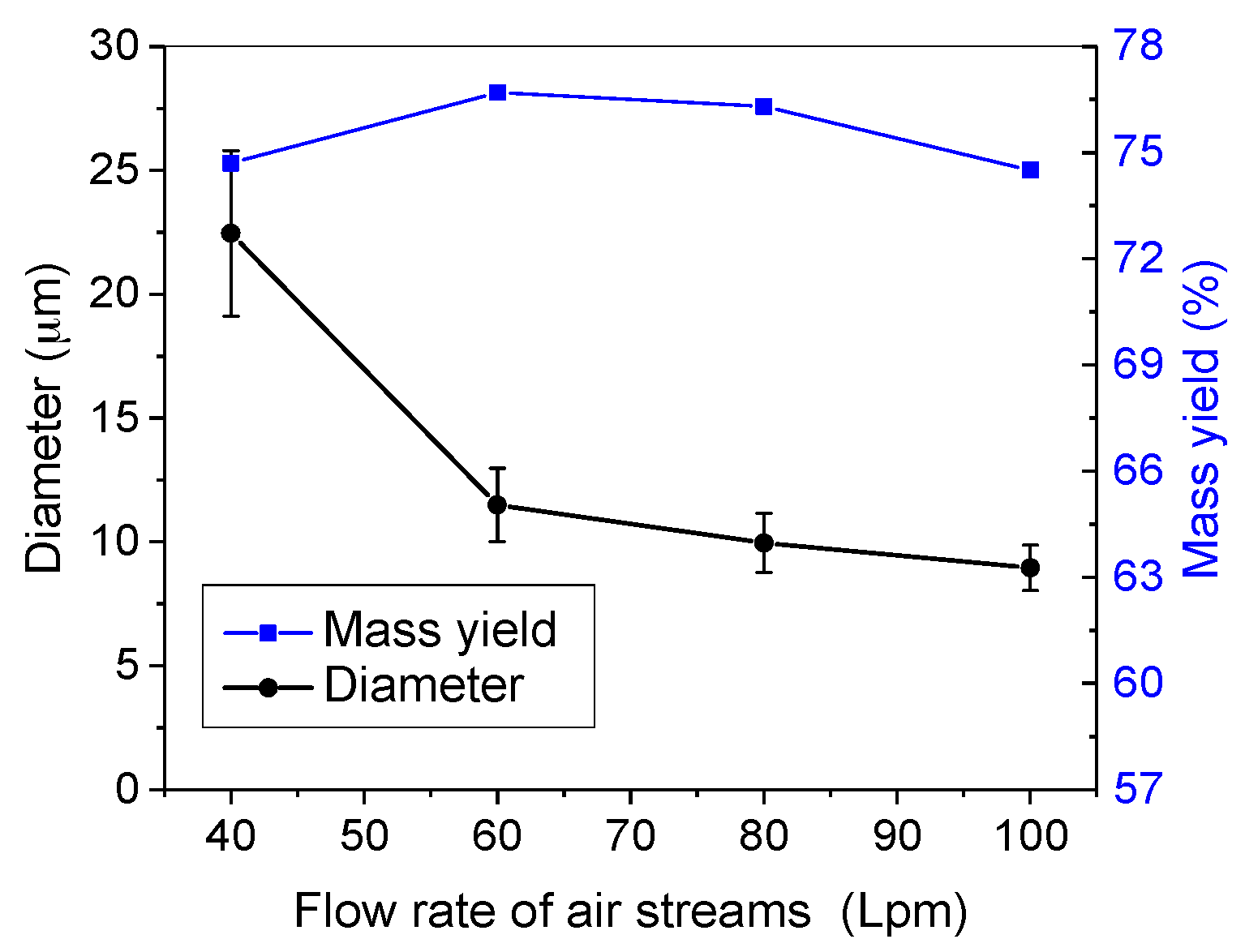
Figure 6.
Diameter variation along the fiber axis within 10 mm and diameter distribution of individual filaments comparing for different carbon fibers (CFs).
Figure 6.
Diameter variation along the fiber axis within 10 mm and diameter distribution of individual filaments comparing for different carbon fibers (CFs).

Figure 7.
Optical microscope images showing the cross-sectional structures of (a) spun fibers (40 Lpm); (b) stabilized fibers; (c) 600 °C-carbonized fibers; and (d) 1050 °C-carbonized fibers.
Figure 7.
Optical microscope images showing the cross-sectional structures of (a) spun fibers (40 Lpm); (b) stabilized fibers; (c) 600 °C-carbonized fibers; and (d) 1050 °C-carbonized fibers.

Figure 8.
Optical microscopy image from rotation of polarized light showing cross-sectional structures of the CF made from small diameter (100 Lpm) pitch fibers.
Figure 8.
Optical microscopy image from rotation of polarized light showing cross-sectional structures of the CF made from small diameter (100 Lpm) pitch fibers.

Figure 9.
Optical microscope images showing a pac-man structure in larger diameter CFs.
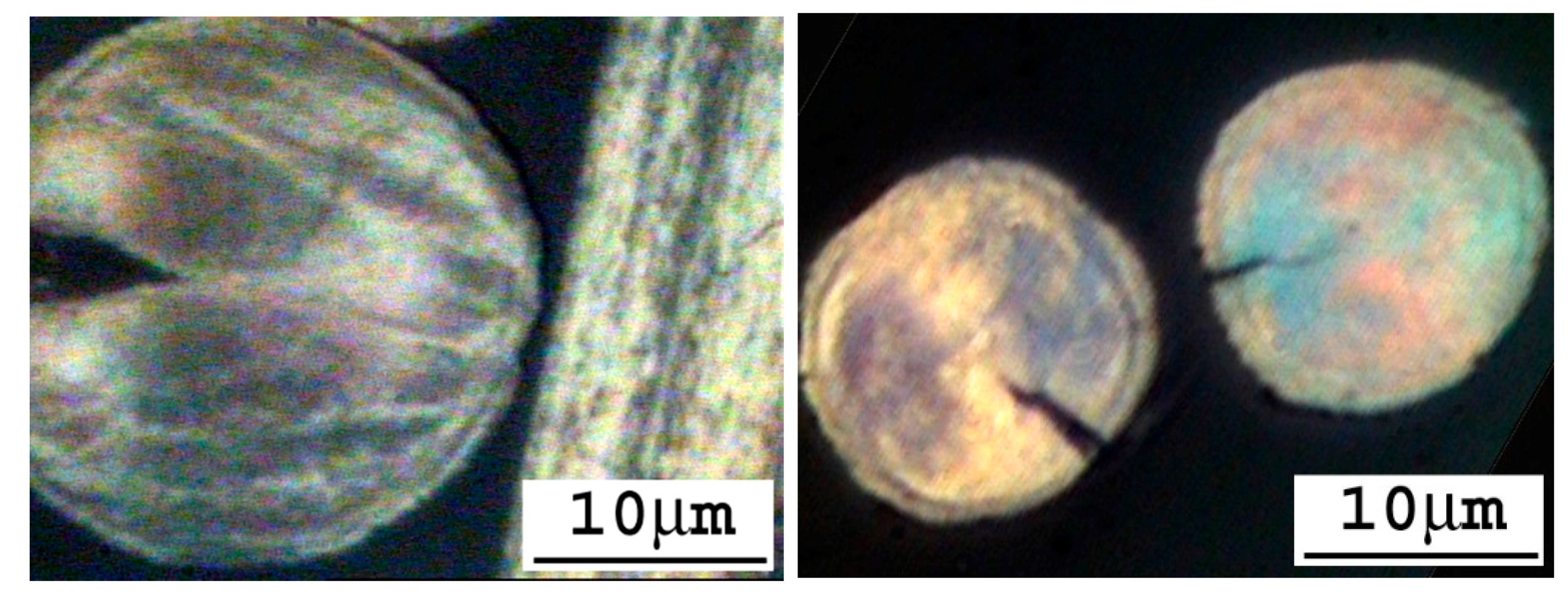
Figure 10.
Scanning electron microscopy (SEM) images showing (a) and (b) larger diameter CFs with a pac-man crack along the fiber axis; (c) and (d) smaller diameter CFs.
Figure 10.
Scanning electron microscopy (SEM) images showing (a) and (b) larger diameter CFs with a pac-man crack along the fiber axis; (c) and (d) smaller diameter CFs.

Figure 11.
X-ray diffraction patterns of solvated MP fibers and the resulting CFs.
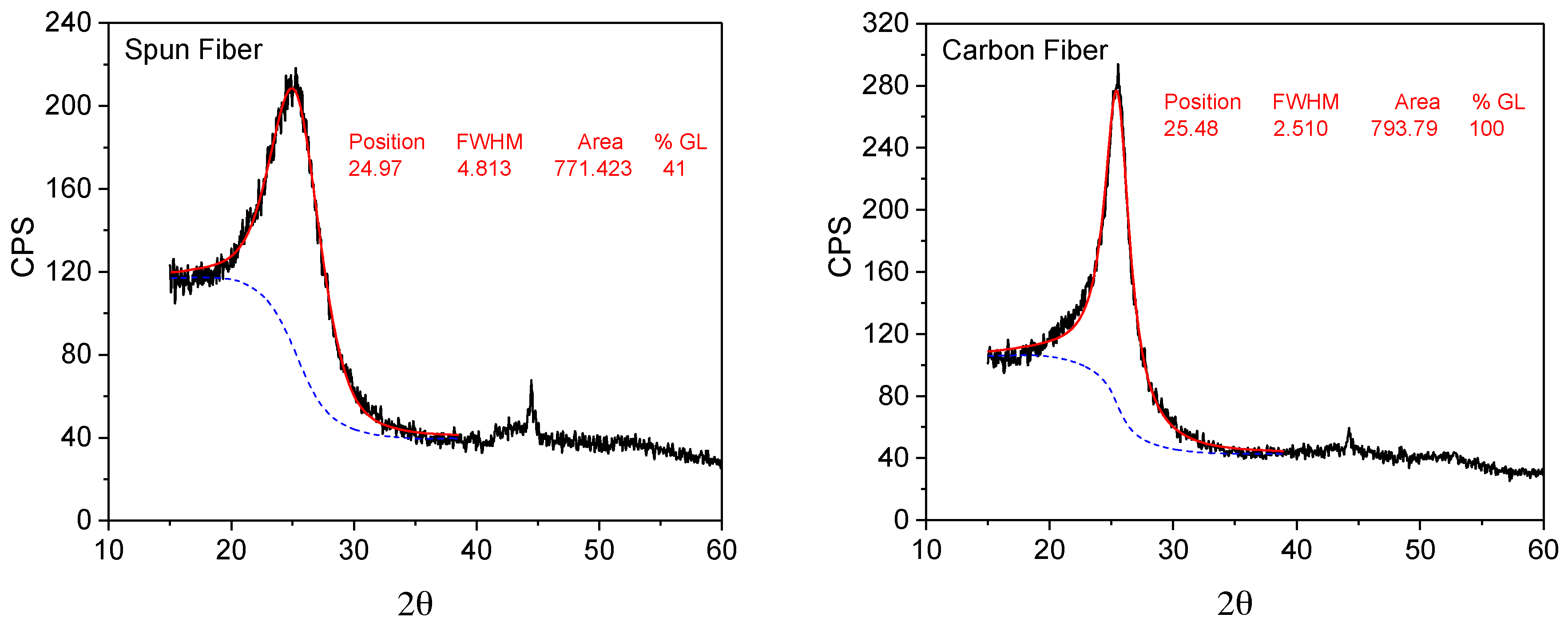
Figure 12.
Typical non-woven CF webs. (a) CF web in a plastic container; (b) fiber orientation under optical microscope.
Figure 12.
Typical non-woven CF webs. (a) CF web in a plastic container; (b) fiber orientation under optical microscope.

Figure 13.
Tensile strength (a) and modulus (b) of the processed CFs as a function of the flow rate of air streams.
Figure 13.
Tensile strength (a) and modulus (b) of the processed CFs as a function of the flow rate of air streams.

Figure 14.
A schematic diagram of a meltblown fiber spinning apparatus and thermal processes for manufacturing pitch-based CFs. 1-pitch feeding; 2-extruder; 3-exhaust vent; 4-ballast pump; 5-spinning pump; 6-filter; 7-spinneret head; 8-primary air stream; 9-secondary air stream; 10-diffuser; 11-air exhaust; 12-spun fiber web; 13-moving belt collector; 14-stabilization oven; 15-carbonization furnace; 16-CF web.
© 2017 by the authors. Licensee MDPI, Basel, Switzerland. This article is an open access article distributed under the terms and conditions of the Creative Commons Attribution (CC BY) license (http://creativecommons.org/licenses/by/4.0/).
Share and Cite
MDPI and ACS Style
Yue, Z.; Liu, C.; Vakili, A. Meltblown Solvated Mesophase Pitch-Based Carbon Fibers: Fiber Evolution and Characteristics. C 2017, 3, 26. https://doi.org/10.3390/c3030026
AMA Style
Yue Z, Liu C, Vakili A. Meltblown Solvated Mesophase Pitch-Based Carbon Fibers: Fiber Evolution and Characteristics. C. 2017; 3(3):26. https://doi.org/10.3390/c3030026
Chicago/Turabian StyleYue, Zhongren, Chang Liu, and Ahmad Vakili. 2017. "Meltblown Solvated Mesophase Pitch-Based Carbon Fibers: Fiber Evolution and Characteristics" C 3, no. 3: 26. https://doi.org/10.3390/c3030026
Note that from the first issue of 2016, this journal uses article numbers instead of page numbers. See further details here.