1. Introduction
Stabilization of polymeric fibers is an essential step for carbon fiber (CF) synthesis [
1,
2] in order to prepare the polymer to resist intense thermal processing by enhancing polymer’s intra- and inter-molecular network through extensive crosslinking [
3]. Nowadays, the main precursors involved in CF synthesis are polyacrylonitrile (PAN), pitch, and rayon. Polyacrylonitrile constitutes almost 80% of the precursors currently used in industrial-scale plants and its stabilization mechanism has been extensively studied throughout the previous century. The major occurring reactions are, namely, summarized to cyclization, dehydrogenation, and oxidation, which lead to a conjugated polymer structure of C=N, C=C, and C=O, respectively [
4]. Simultaneously, some secondary crosslinking reactions may occur during the process. However, the high cost of currently-used precursors demonstrates the urgent need to investigate alternative precursors in order to reduce the cost of production and enable wide commercialization of CF materials [
5].
In this direction, polyolefins are considered as promising precursors for CF synthesis in respect of their low cost and high process-ability into fibers via the melt-spinning method. It should be mentioned that replacing the solvent-based techniques of fiber spinning that are used to produce current carbon fiber precursors, such as PAN, will require less energy, while the production rate will rise significantly to provide a more profitable processing plant. Moreover, their high carbon yield after the carbonization process (60–80%) may overcome the corresponding value of PAN-based CFs.
According to the literature [
6], it may be remarked that polyolefin-like structures cannot be thermally stabilized. Moreover, the presence of oxygen in atmospheric air initiates the oxidation reactions at elevated temperatures, resulting in the degradation of polyolefin fibers instead of promoting crosslinking. However, this behavior was considered to be altered with softwood kraft lignin (SKL) addition [
7], so it is worth mentioning that a review of thermal stabilization and the occurring crosslinking is important [
8]. In general, when employing polyolefins in CF synthesis, the common techniques to obtain an infusible crosslinked fiber structure are related to either the use of peroxide compounds, or employing sulfonation (chemical modification) [
9,
10], or the use of the radiation oxidation method (modifying the fiber by using various types of radiation) [
11].
In the present study, blend polymeric fibers were produced via the melt-spinning process and evaluated in respect of their stabilization behavior. These fibers consist of high-density polyethylene (HDPE) matrices together with SKL. The blend ratio of the HDPE/SKL was 90/10 by weight (HDPE/SKL (90:10)). The stabilization process includes the treatment of the fibers with sulfuric acid under elevated temperature. Due to the lack of nitrile triple bonds in the used polymers, a stabilization process may offer a conjugated structure of C=C and C=O via dehydrogenation, oxidation, and crosslinking reactions in order to enhance thermal properties. Furthermore, other bonds could be produced considering the interaction with lignin or other employed chemical processes [
12,
13,
14].
2. Results and Discussion
2.1. Characterization of Chemically-Stabilized HDPE/SKL Fibers
2.1.1. SEM-EDS Investigation of HDPE/SKL Fibers
The produced samples were characterized in respect of their morphology and elemental analysis via scanning electron microscopy (SEM) and energy dispersive X-ray spectroscopy (EDS). For the successful stabilization of the fibers, it is required that the sulfur atoms, coming from sulfuric acid, have to form sulfur bridges onto the polymeric chains of HDPE and lignin. These bonds reinforce the polymer chains making them more durable and sturdy [
5].
Table 1 presents the tabulated values of wt % element concentration of the produced HDPE/SKL fibers prior and after sulfonation, as well as after the carbonization procedure. Regarding
Table 1, it may be remarked that the obtained results are in accordance to literature, in which carbon fibers are produced from fibers with a sulfur content of 1.0–3.5 wt % [
5]. Consequently, it should be mentioned that the sulfur content of the HDPE-SKL fibers is adequate to perform carbonization. The highest values of wt % sulfur concentration are observed when the treatment temperature is raised in the region of 130 °C. This result can be ascribed to the diffusion of sulfur along the fiber axis at elevated temperatures.
All the produced samples were carbonized after the chemical treatment from 600 °C to 900 °C using a ramp temperature program in a pyrolysis furnace. The samples were left to cool down to 300 °C, and then the apparatus was opened and exposed to atmospheric air. However, taking into consideration the morphological characterization of the carbon fiber, it was noticed that the single-stage sulfonation was ineffective and that a carbon fiber was produced only when the HDPE/SKL fibers were treated with an additional sulfonation step (firstly, thermal heating at 100 °C for 5 h, and then thermal heating at 150 °C for 1 h).
Figure 1 and
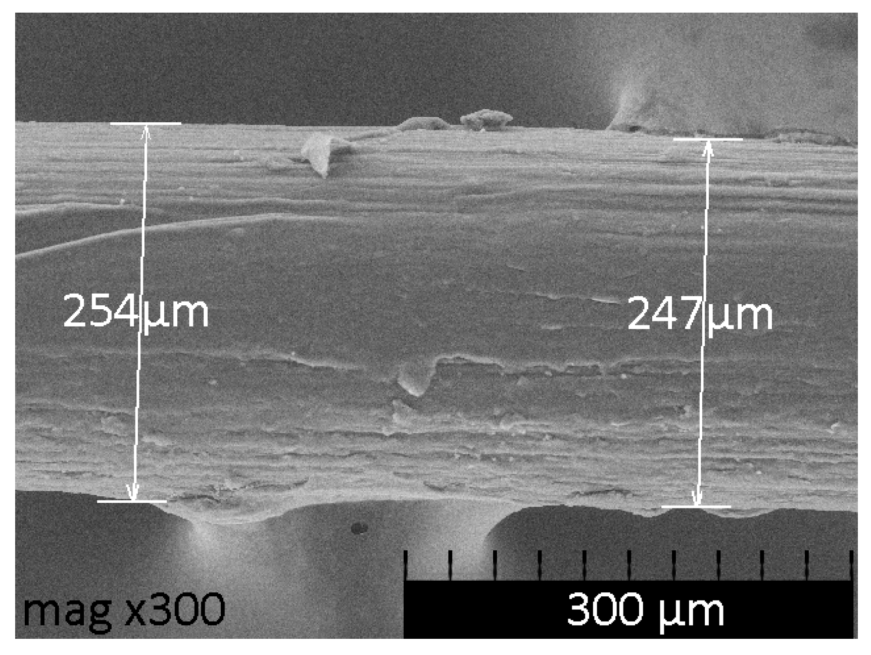
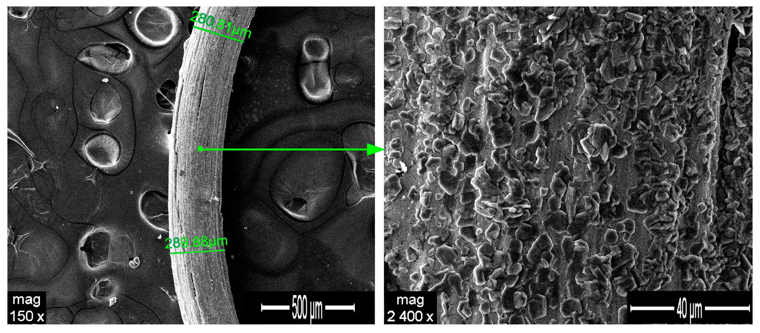
Figure 2 illustrate the SEM images of the untreated HDPE/SKL (90:10) fiber and the two-stage sulfonated fiber, respectively. Concerning the fibers’ diameters before and after sulfonation (
Figure 1 and
Figure 2), it can be seen that the untreated (non-sulfonated) fiber had an average diameter of 250 µm, while the sulfonated one demonstrated a diameter of approximately 290 µm. This fact indicates that during sulfonation the surface of the fiber was swollen and its density was increased due to the modification, which made the fiber thicker and more rigid. This outcome can be attributed to the enhanced thermal treatment of the fiber. Furthermore, as it is demonstrated in
Figure 2, the fiber outer surface becomes more rugged after sulfonation, due to the sulfur bridges that are formed, a result that is confirmed by the corresponding EDS analysis, as an increase in sulfur amount in the fiber elemental composition is observed.
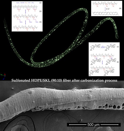
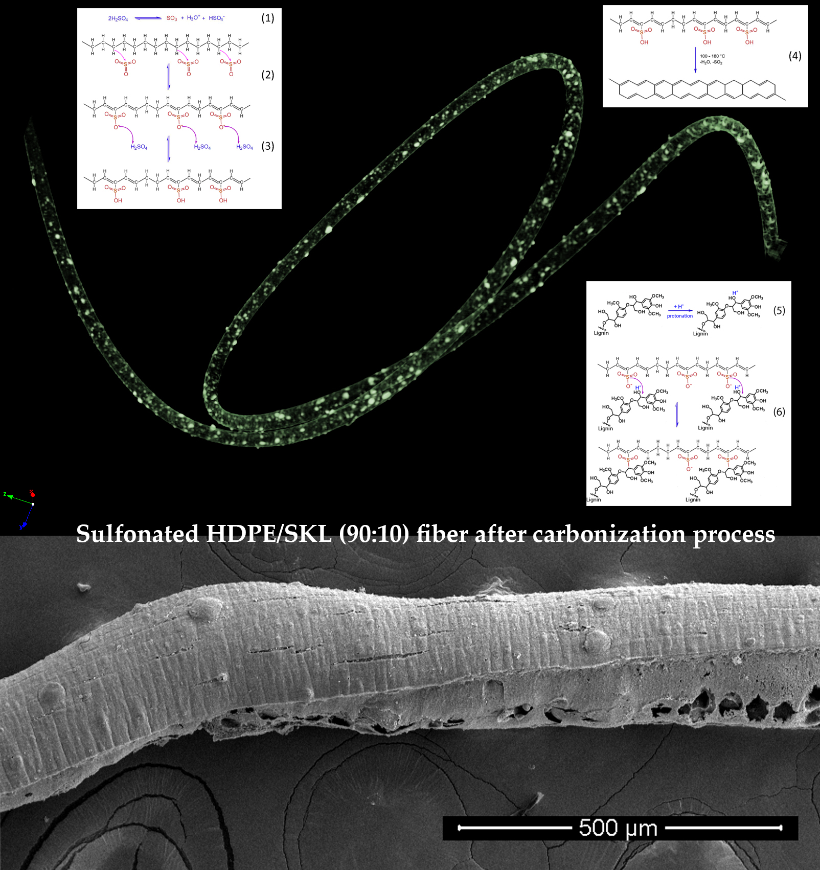
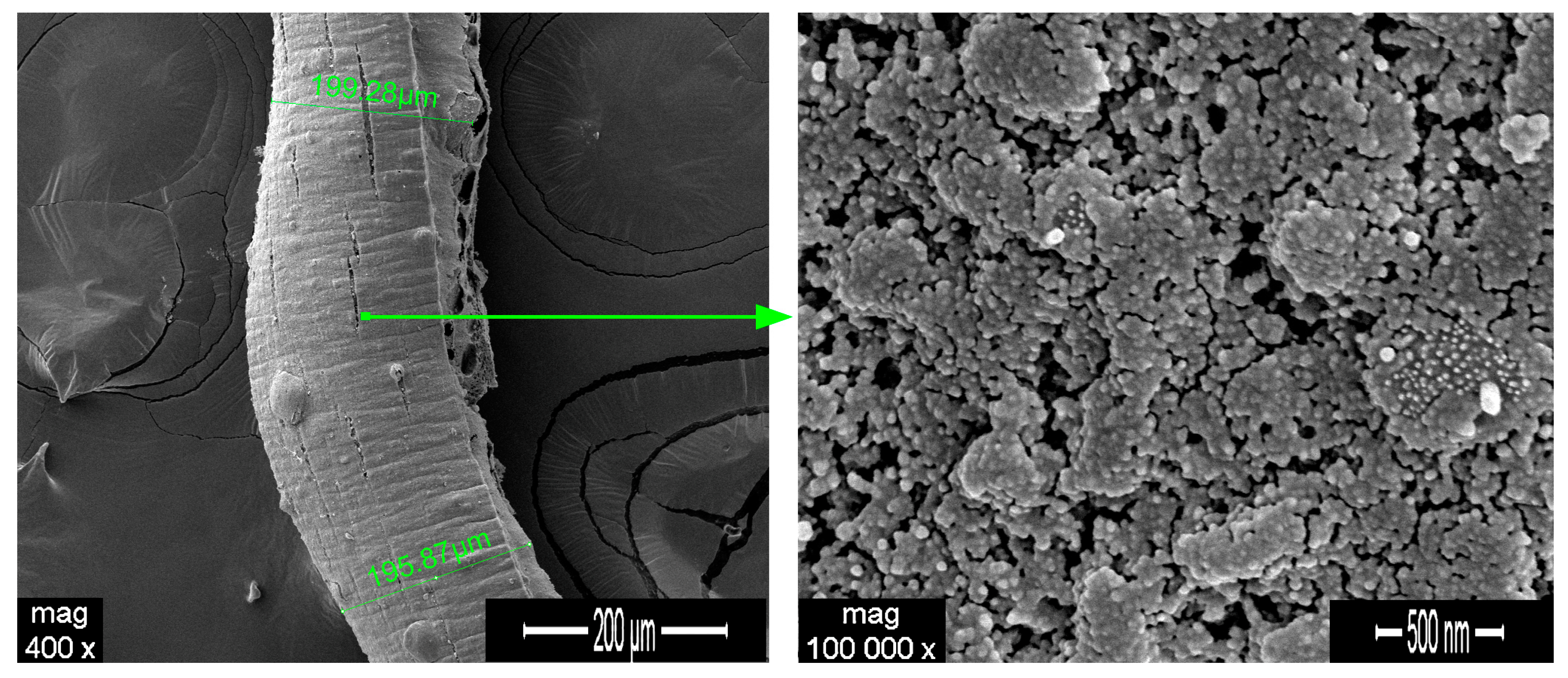
Figure 3 illustrates the SEM images of the sulfonated HDPE/SKL (90:10) fiber after the carbonization process (two-stage sulfonated-carbonized). Concerning this figure, it is clearly denoted that the fiber diameter is reduced after exposure to elevated temperature compared to the diameter of the fiber prior to the carbonization process (
Figure 1 and
Figure 2). The observation of the fiber surface at higher magnification (100,000×) reveals high porosity, a result that is further confirmed by the micro-CT analysis that is presented below, in
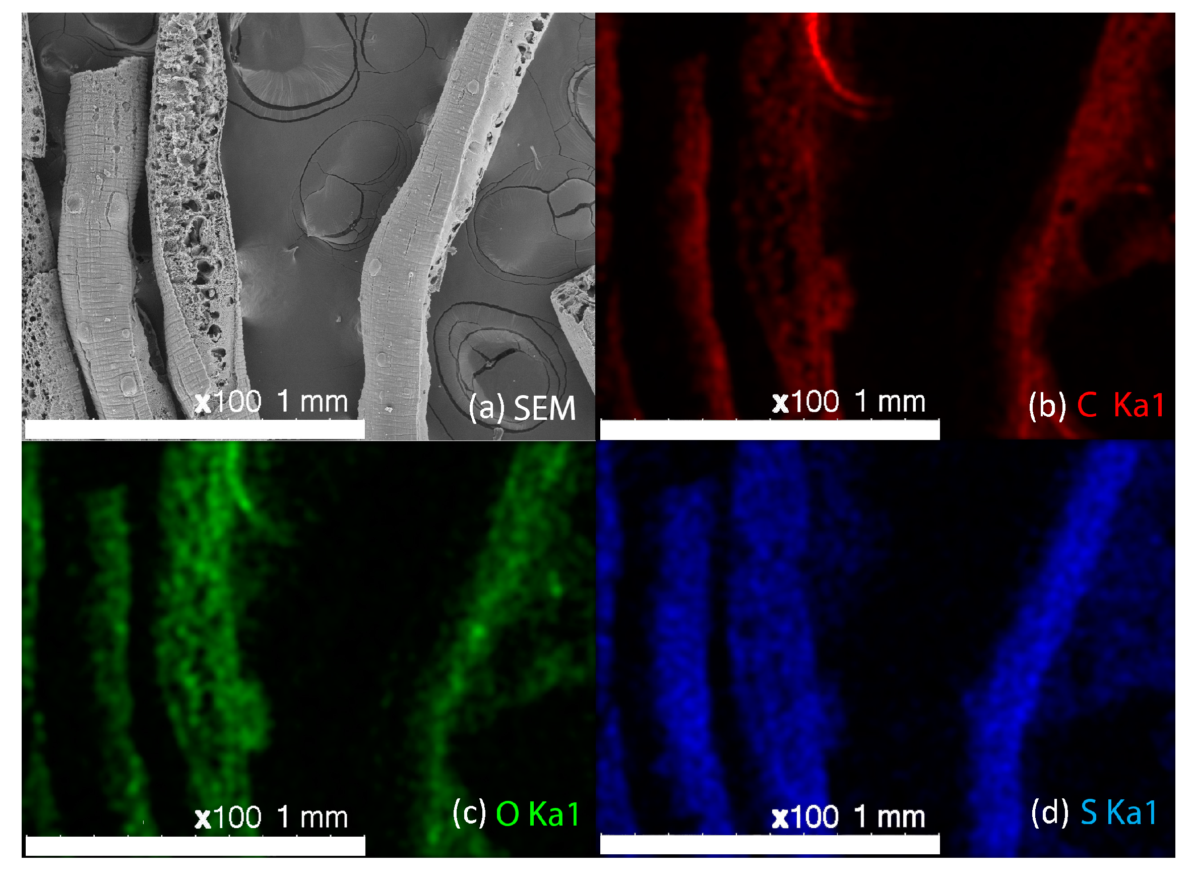
Section 2.1.4. The EDS elemental mapping together with the corresponding SEM image are depicted in
Figure 4. Taking into account the sulfur in elemental mapping, it is clearly denoted that the sulfur groups have been introduced to the fibers successfully, and are well dispersed in the whole fiber.
2.1.2. Attenuated Total Reflectance Fourier Transform Infrared Spectroscopy (FTIR)
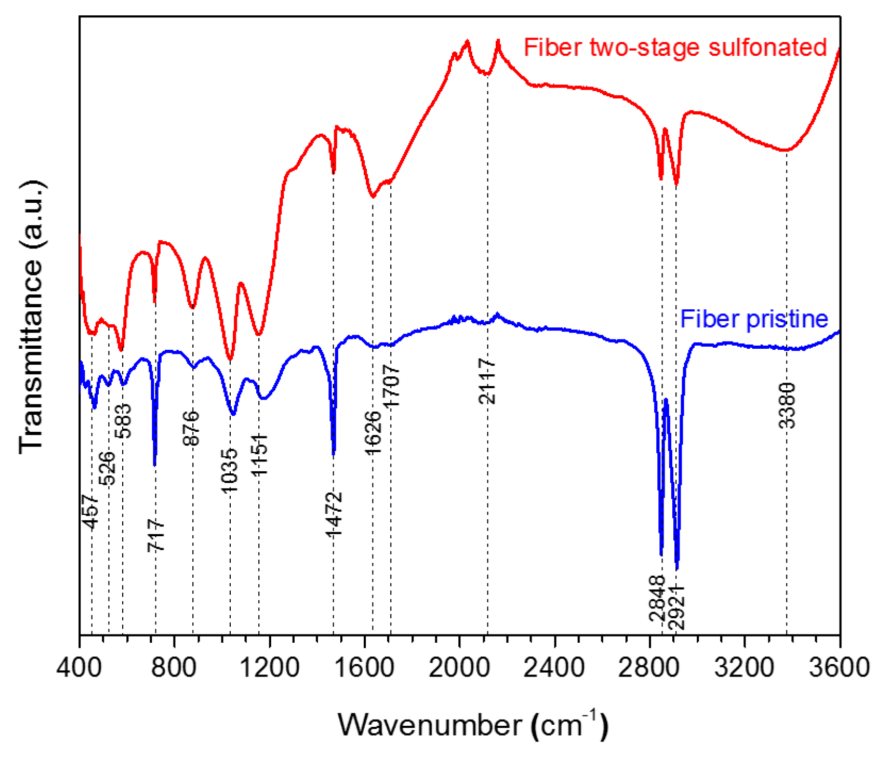
The produced HDPE/SKL (90:10) fiber samples were characterized via FTIR. The bond vibrations, which are ascribed to each peak are presented in
Table 2 and the respective FTIR graph is demonstrated in
Figure 5. Taking into consideration the spectra, it may be remarked that the intensity of the O-H bond on account of the hydroxyl and carboxyl groups was increased at 3380 cm
−1, while the intensities of C-H stretching vibration at 2921 cm
−1, 2848 cm
−1, and CH
2 binding at 1472 cm
−1 have been reduced in the graph of the sulfonated fiber. This shows that sulfonation was carried out by substitution of an H-branch across the HDPE/SKL (90:10) fiber by a sulfonic acid group –HSO
3−, and was bound to another H-branch to form sulfone (SO
2). In addition, the cross-linking between the polymeric chains lead to the formation of O=S=O that was confirmed with both a symmetrical and an asymmetrical stretching vibration at 1151 cm
−1 and 1035 cm
−1. Moreover, peaks of S-O-C bonds that are formed due to deformation of =C-H bonds in the sulfonated fiber were observed at 876 cm
−1. Furthermore, the oxidizing effect of sulfuric acid on HDPE/SKL (90:10) fiber is materialized through the formation of carbonyl and carboxyl groups at 1707 cm
−1, while the acid dehydrogenating effect is ascribed to the peak at 1626 cm
−1 [
12]. Thus, it is assumed that sulfonation was successfully performed in the virgin fiber considering the above treatments.
2.1.3. Thermogravimetric Analysis—Differential Scanning Calorimetry (TGA-DSC) Characterization
All the HDPE/SKL (90:10) fibers were tested for their thermal stability via sulfonation in order to evaluate the effectiveness of chemical stabilization. The samples were characterized in inert atmosphere (N
2 flow) by applying a heating rate of 20 °C/min to simulate carbonization conditions.
Figure 6 depicts the TGA-DSC diagrams of the untreated HDPE/SKL (90:10) sample. Initially, a mass loss is observed up to 300 °C due to the residual solvent evaporation, as the sample was tested without any prior drying step. As the temperature rises, the weight of the sample is further reduced due to the occurring exothermic carbonization reactions, as demonstrated by DSC, which simultaneously produces gas emission of byproducts, namely, CO, CO
2, SO
x, H
2S, and other carbon compounds. These are produced due to random chain scission in non-crosslinked fiber regions.
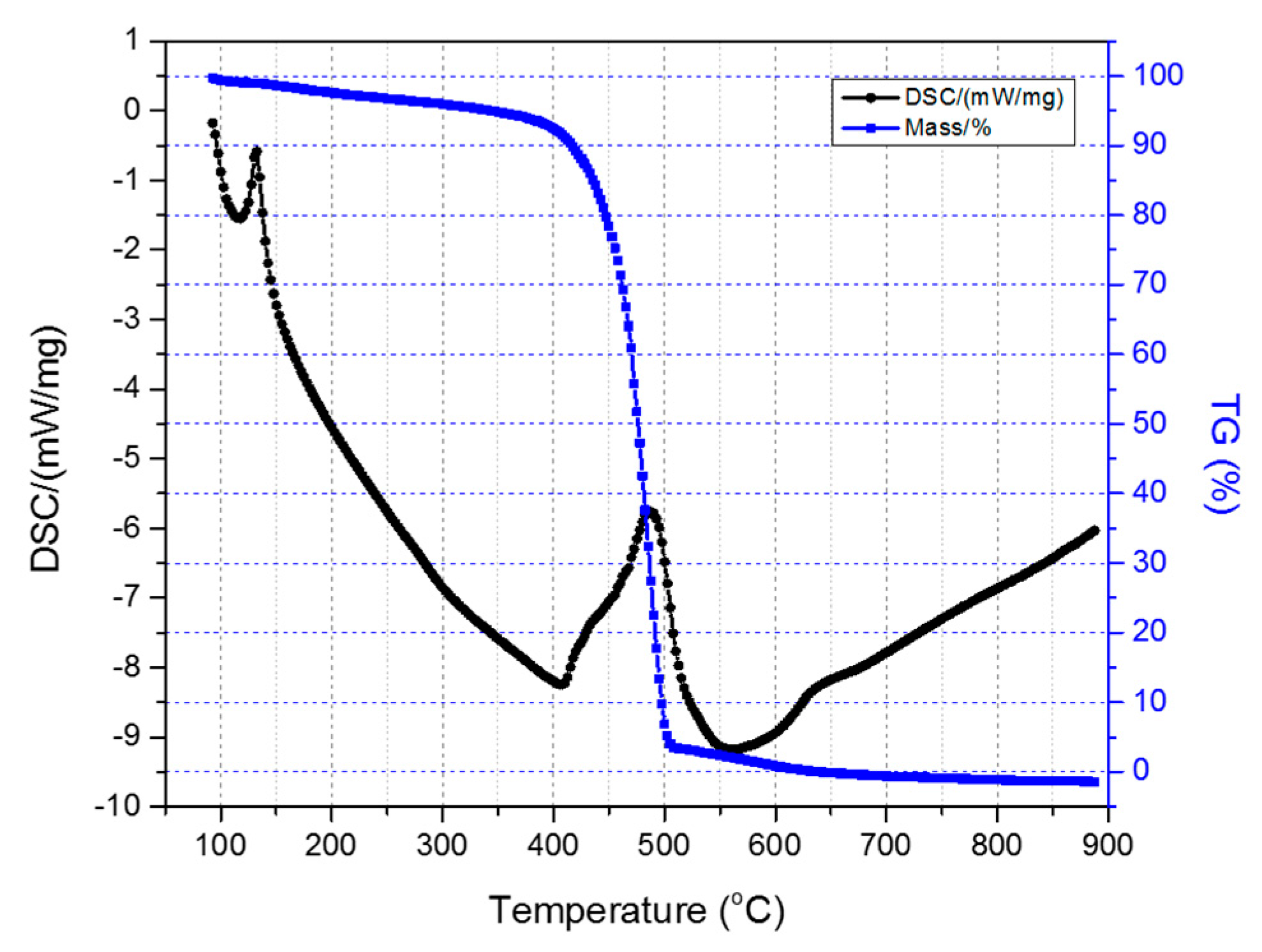
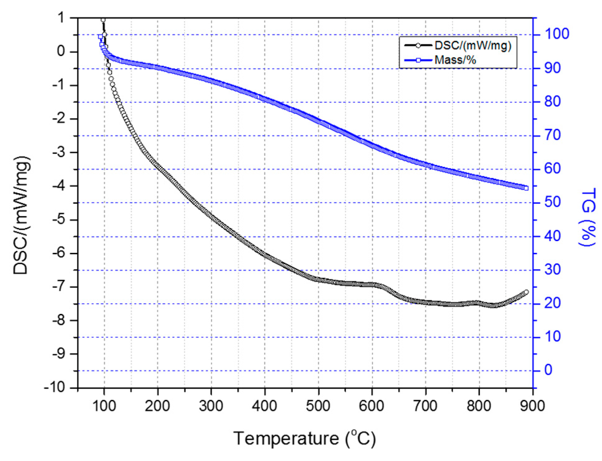
Figure 7 illustrates the TGA-DSC diagrams of the two-stage sulfonated HDPE/SKL (90:10) sample (initial thermal heating at 100 °C for 5 h, and then thermal heating at 150 °C for 1 h). Taking into account the presented diagrams, it is clearly denoted that after conducting the thermal characterization, a residual mass of 54.4% was obtained, and considering the initial loss due to the remaining solvent, carbonization yield may reach a level of 62.5%. Furthermore, the crosslinking index (γ%) was estimated by the ratio of the melting enthalpy change (due to chemical treatment) to the melting enthalpy of the initial fiber.
The results are tabulated in
Table 3. Considering the obtained values, it may be remarked that the sulfonation treatment of the fibers either at 90 °C for 3 h and 5 h or at 110 °C for 3 h, demonstrates the best crosslinking percentage. Consequently, taking into account the aforementioned results, it is concluded that temperature should be set between 90 °C and 110 °C, and the duration up to 5 h in the first stage of the sulfonation process in order to achieve optimum crosslinking.
Taking into consideration that none of the fibers presented in
Table 3 retained their morphology after heat treatment up to 1000 °C, this outcome made the need for the incorporation of a second sulfonation stage at elevated temperature imperative. Thus, the treatment, which at first includes thermal heating at 100 °C for 5 h and then thermal heating at 150 °C for 1 h was adopted.
2.1.4. Morphology/Micro-Computed Tomography Characterization—Physical Properties of Precursors and Carbonized Fiber
The pixel size in the obtained output data of micro-CT characterization represents the proximity of the sample to the X-ray source. Fractal dimension is a ratio providing a statistical index of how detail in a pattern changes with the scale at which it is measured. Moreover, porosity or void fraction is the measure of void spaces in a material, and it is a fraction of the volume of voids over the total volume, between 0 and 1. Micro-CT analysis was performed on the HDPE/SKL (90:10) sulfonated fiber, in order to evaluate the impact of stabilization on fibers morphology. The arithmetical results of the micro-CT analysis are demonstrated in
Table 4, while the Micro-CT images are presented in
Figure 8,
Figure 9 and
Figure 10.
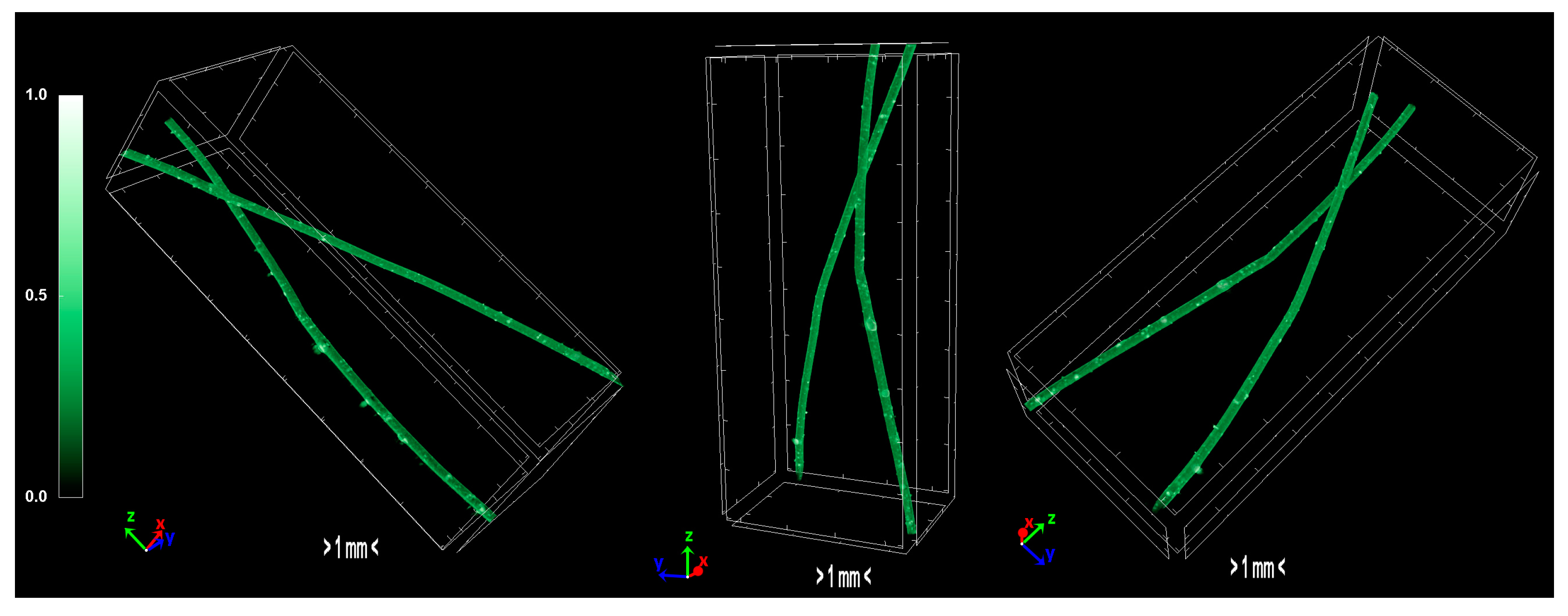
Regarding the Micro-CT analysis, it is evidenced that the inner pores of the material are being reduced going from HDPE/SKL (90:10) to the sulfonated HDPE/SKL (90:10) and then to the carbonized HDPE/SKL (90:10) fibers. This means that the fiber becomes stronger and sturdier due to lignin enrichment, and further due to sulfonation. Additionally, the volume of open pore space increases with the addition of lignin, as well as with the sulfonation, making the fiber more uniform and increasing the chances of a smooth carbonization with controlled heating across the fiber surface. While the volume of closed pores is maintained, their number is slightly increased with the incorporation of lignin, but is decreased significantly after sulfonation.
This fact indicates that the sulfonation has an impact on the fiber surface and morphology through crosslinking. Furthermore, the object surface to volume ratio decreases with lignin and even more after sulfonation but increases after carbonization, while the thickness increases after sulfonation and decreases after carbonization, denoting that the fiber surface becomes smoother, durable, and obtains enhanced properties. This indication is also reinforced by the object surface density. While it has a moderate value for the HDPE/SKL (90:10) fiber, as expected, it shows a decrease for the sulfonated HDPE/SKL (90:10) sample while, after carbonization, it increases even more than the plain HDPE/SKL (90:10) fiber.
On account of this phenomenon, it can be deduced that the irregular compounding of the two materials (HDPE and lignin) in the holder of the extruder leads to a denser and maladjusted surface of the fiber. However, the sulfonation appears to solve that problem since the object surface density of the sulfonated HDPE/SKL (90:10) fiber is reduced approximately to that of the plain HDPE fiber. The same trend is observed for the structure linear density. Thus, following this procedure, a modified fiber is obtained, with properties that are roughly similar to those of a commercial polymer.
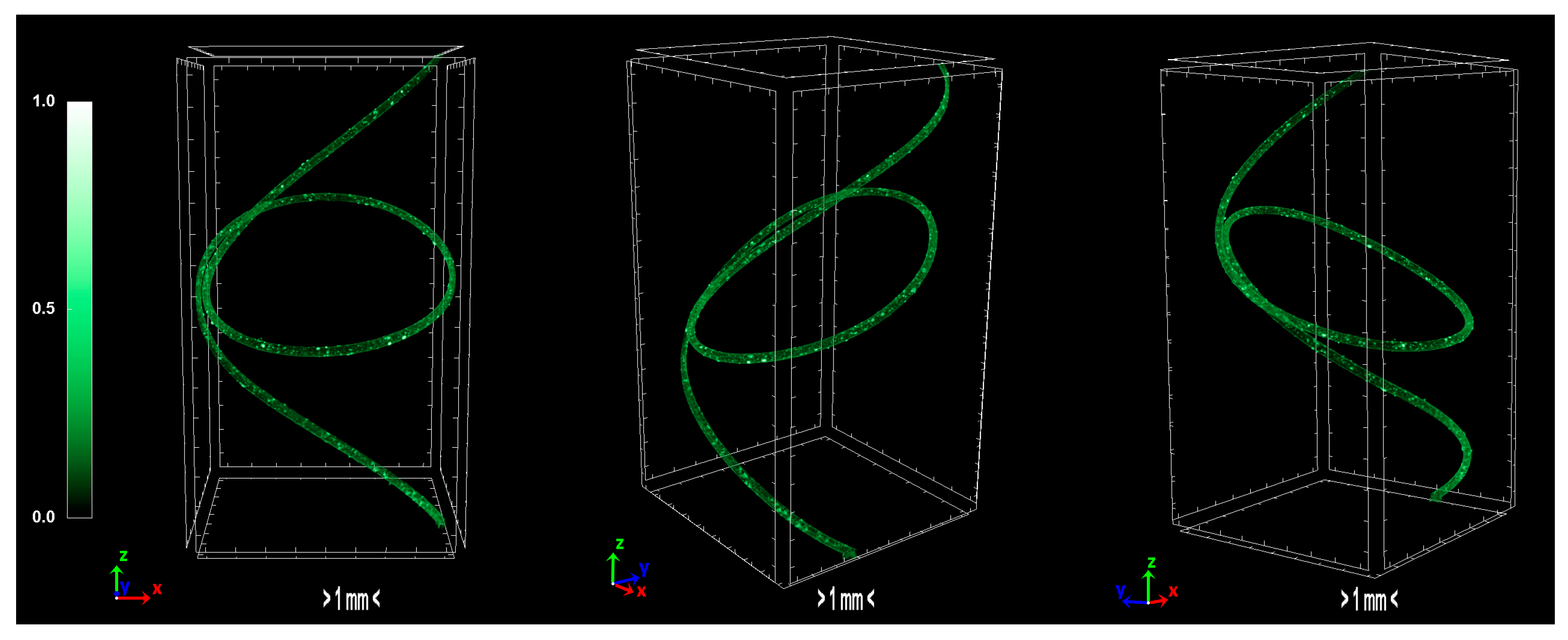
The produced carbon fibers were studied via micro-CT to determine the physical properties, and were compared to the precursor fibers and recent literature. According to micro-CT characterization, it can be noticed that the total porosity of the carbonized fiber is increased compared to the sulfonated fiber, as expected due to the uneven distribution of sulfur along the fiber axis during sulfonation [
15]. The fiber is treated in higher temperatures to overcome the reported issue, however, the release of gases in non-crosslinked areas results to the growing of larger pores. Furthermore, the derived carbon fiber is thicker and denser than the sulfonated fiber, a fact which suggests that the carbonization procedure was successfully performed and produced a durable fiber. In addition, the degree of anisotropy is severely reduced after sulfonation; the sulfonated fiber demonstrates half the value of anisotropy compared to the non-treated fiber. This phenomenon suggests that the sulfonation process is a decisive factor in the orientation of the fibers, while carbonization does not present a significant change of that parameter. Moreover, micro-CT studies on internal geometry of carbon fiber tapes [
16] have shown a similar morphology as the one obtained in this study. Additionally, tomography studies on low-density carbon fiber materials and composites present similar physical properties [
17,
18]. Investigation of carbon fiber fatigue and breakage via micro-CT modelling demonstrated contiguous initial qualities [
19,
20,
21], which indicates that the carbonization progressed at a substantial level. The physical properties of micro-CT analysis are presented in
Table 4 and the tomography images of the carbonized fibers are demonstrated in
Figure 11.
2.2. Sulfonation and Crosslinking Mechanisms
Thermal treatment of HDPE was considered to lead in a conjugated polymer structure through dehydrogenation and oxidation reactions. Oxidation was expected to create oxygenated groups in the fiber structure via radical mechanism, in type of R
·, RO
·, or ROO
· groups. However, the inability of the polymer chain to obtain the esterified-like structure of ROO
· did not promote the increase of molecular weight (M
w) or any kind of crosslinking; thus, the fibers melted during oxidative thermal stabilization treatment [
22].
The effect of lignin addition was imperceptible concerning crosslinking and the increase in heat resistance of the fibers during thermal treatment, possibly due to low SKL content. In most cases, apart from pyrolysis treatment where decomposition occurred, the fibers seem to melt rather than degrade (oxidation reactions do not occur, no color change). This phenomenon implies that regardless of the treatment conditions, the polymeric fiber retains its thermoplastic qualities for both short-time and extended thermal treatment. As a result, it could be assumed that there was no progress in any crosslinking reactions, while such treatment would also be time and energy consuming. Consequently, the process parameters should be reconsidered in order to support an industrially viable process [
23]. Therefore, chemical modification was applied in order to promote crosslinking in the as-spun fibers. A 3 × 3 factorial experimental design was used to examine the temperature and time effects in the structure, elemental composition along the fiber axis, morphology, crosslinking, and degradation due to sulfonation.
Treated fibers demonstrated changes in their macroscopic behavior, indicating partial or complete sulfonation. First of all, the color change from brown to black is attributed to sulfonation reaction, while stiffness and hardness are increased inducing a thermoset character in the sulfonated fiber. The incorporation of several bonds, characteristic of sulfonation in HDPE and polyolefins, in general, was also confirmed by the FTIR characterization [
24,
25].
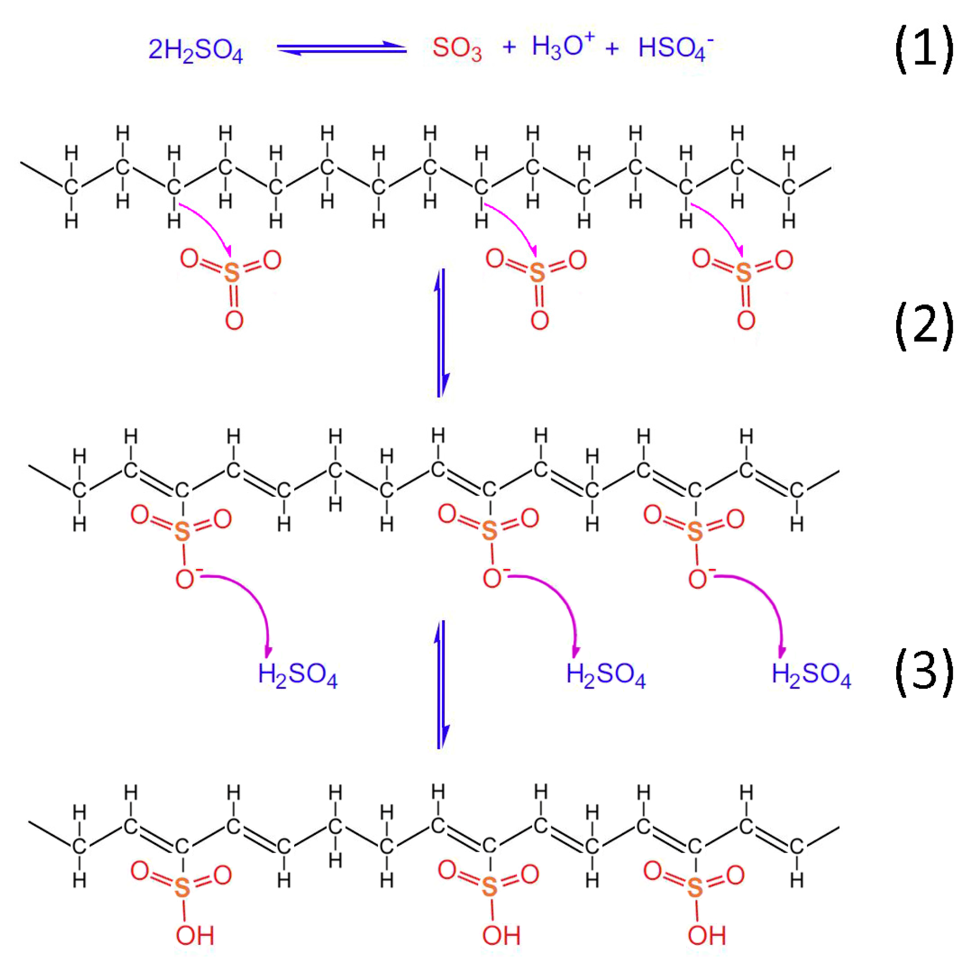
Taking into account the TGA/DSC analysis, it is evidenced that the optimum crosslinking occurs at a two-step sulfonation reaction (firstly, thermal heating at 100 °C for 5 h. and then thermal heating at 150 °C for 1 h). The sulfonated fiber, under the abovementioned conditions, sustains over 80% of its total weight. This fact classifies it as a promising precursor for CF production, under the appropriate carbonization process. Considering the aforementioned results, it may be remarked that the reactions 1–6 take place during sulfonation (
Figure 12,
Figure 13 and
Figure 14). Firstly, two molecules of H
2SO
4 react together producing SO
3, H
3O
+ and HSO
4− through a hydrogen-oxygen protonation via a two-way reaction (reaction 1). One H
2SO
4 molecule is the reactant and the other one is the catalyst [
26]. After that, there is a nucleophilic carbon addition of the aliphatic hydrocarbon polymer to the electrophile SO
3 molecules (reaction 2) and then to the excess of H
2SO
4 molecules, which results in the production of polyacetylenic species that contain sulfonic acid groups (reaction 3) [
27].
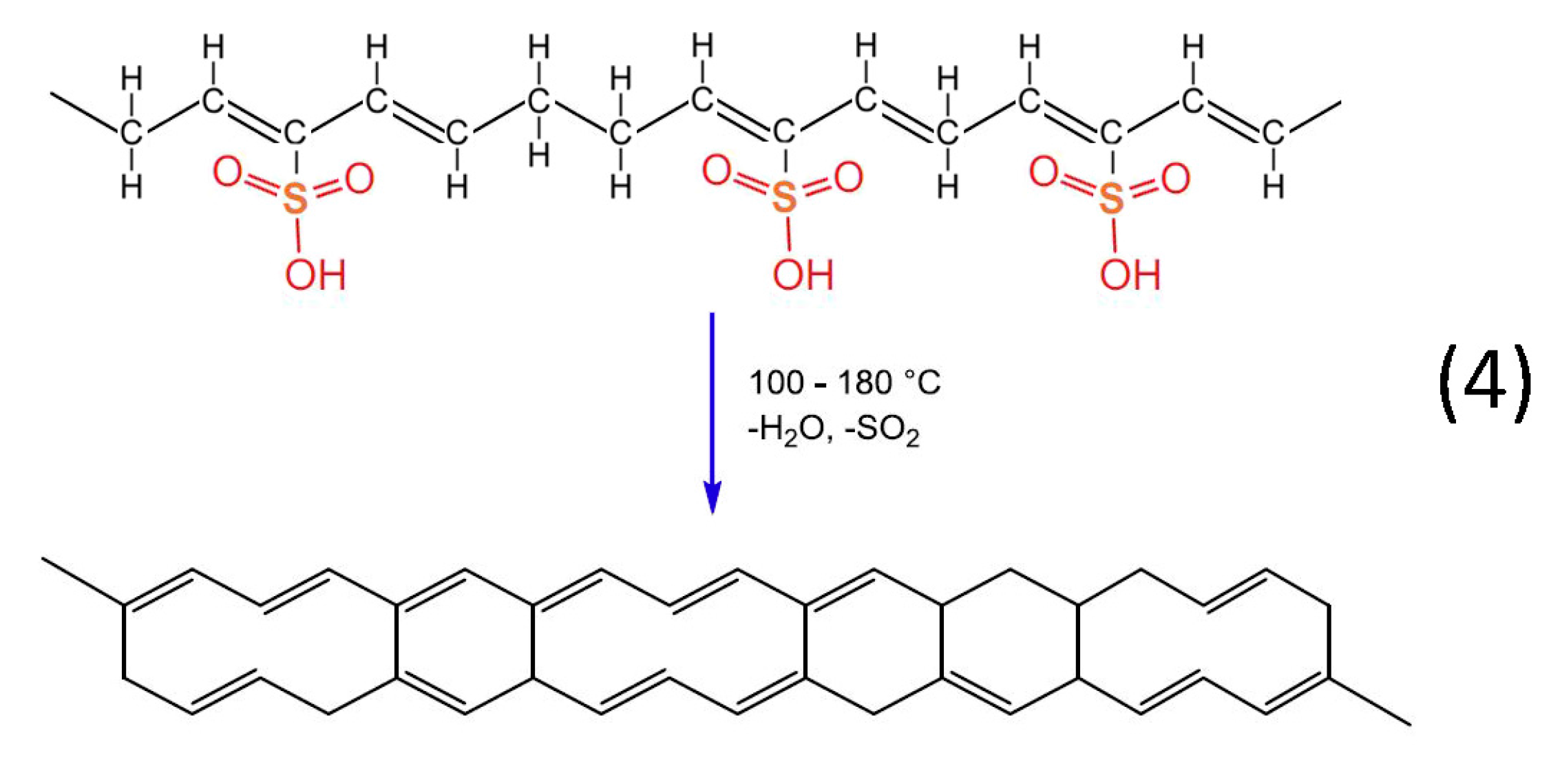
Heat treatment of the formatted hydrocarbon polymer with polyacetylenic species and sulfonic acid groups in a temperature range from 100 °C to 180 °C results in desulfonation along with crosslinking among the hydrocarbon polymers and the formation of aromatic structures (reaction 4). Furthermore, heat treatment over 600 °C in inert atmosphere results in the formation of a graphite structure [
22].
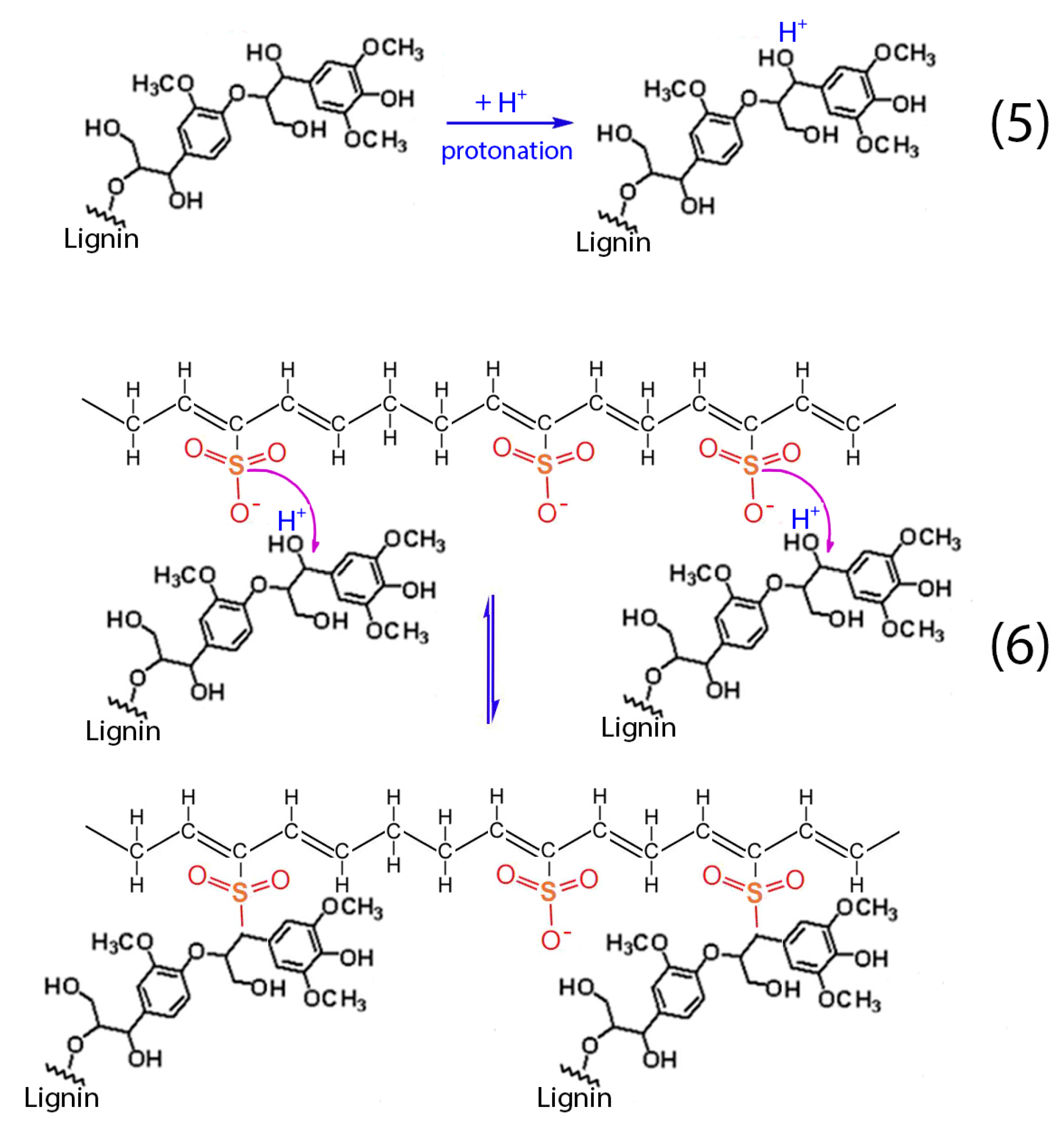
Apart from the aforementioned reactions (1–4), the presence of lignin into H
2SO
4 results to the protonation of the non-phenolic lignin structures, according to reaction (5). Then, these structures react with the formatted hydrocarbon polymer containing polyacetylenic species and sulfonic acid groups as stated in reaction (6) [
28]. The aforementioned cross-linking among the hydrocarbon polymers as well as the sulfuric bridges between the hydrocarbon polymers and lignin lead to the successful stabilization of the HDPE/SKL fibers.
3. Materials and Methods
3.1. Materials
High-density polyethylene (Sigma Aldrich, St. Louis, MO, USA, Mw~125,000) in the form of pellets, was used in the experiments. Hydrochloric acid (HCl 37%, Fisher Chemicals, Waltham, MA, USA) and sulfuric acid (H2SO4 96%, Sigma Aldrich, St. Louis, MO, USA) were used as received without further purification. Softwood kraft lignin (SKL) was obtained from Westvaco Corp. (Indulin AT, MWV, Norcross, GA, USA) and was treated with HCl 0.1 M prior to its use. All melt-spinning blends were dried in a vacuum oven for 24 h prior to their extrusion.
3.2. Preparation of Carbon Fibers (CFs)
Two stabilization techniques were applied in the fiber specimens to investigate the effect in their chemical structure and thus to prepare the fibers for their conversion to carbon fibers: thermal stabilization and chemical stabilization. Thermal stabilization was examined in both oxidative (atmospheric air) and inert (argon flow) atmosphere in order to evaluate the effect of thermal processing. In the case of chemical stabilization (sulfonation) the blend fibers were immersed in H2SO4. The processes are described in detail in the following sections.
3.3. Characterizations
The morphology as well as the elemental composition of the synthesized fibers, were evaluated via scanning electron microscopy with a Hitachi TM3030 tabletop microscope equipped with an energy dispersive X-ray spectrophotometer (EDS) system (QUANTAX 70), and with ultra-high-resolution scanning electron microscopy (UHR-SEM) using a NOVA NANOSEM 230 (FEI Company, Eindhoven, The Netherlands). ATR-FTIR analysis was conducted on a Cary 630 spectrometer (Agilent) with an operating wavelength range at 4000–400 cm−1 at a resolution of 4 cm−1. The thermal behavior evaluation of the produced fibers was conducted via TGA/DSC using a simultaneous TG-DTA/DSC apparatus (STA 449 F5 Jupiter). The temperature range was from 25 °C to 1000 °C and nitrogen was used as the inert gas.
The internal structural information of the samples was examined via micro-computed tomography (micro-CT) using a compact desktop Bruker micro-CT, 3D X-ray scan system, SkyScan 1272. The system consists of a microfocus sealed X-ray source which operates at 20–100 kV and 10 W (<5 µm spot size @ 4 W) X-ray detector with a maximum resolution of 11 megapixels (4032 × 2688 pixels) and a 14 bit cooled CCD fiber optically coupled to a scintillator. During the observation, the specimens were fixed on a rotational stage, the distance between the rotation axis and the radiation source was set from 6 mm to 12 mm and the pixel resolution was set to 2016 × 1344 in order to obtain reliable images. To ensure sufficient image resolution during CT acquisition process, the sample was positioned in the scanner’s field of view and the air surrounding the sample was excluded from the scanning area. The X-ray tube voltage was set to 40 kV and X-ray tube current was set to 40 lA for all the specimens. After the acquisition of the X-ray projection images, the 3D image was reconstructed by the image processing software of the X-ray CT system (NRecon). Multiple images stacked through the out-of-plane direction for each specimen were used for image processing and calculations. The produced 3D images resulted after processing of the reconstructed dataset with the respective software (CTVox, CTVol). The arithmetical 3D analysis of all sample parameters was performed using CT analysis software (CTAn).
3.4. Thermal Oxidative Stabilization
Thermal Oxidative Stabilization Apparatus
Thermal oxidative stabilization experiments were conducted in a pyrolysis furnace and the temperature ranged between 25 °C and 400 °C. The exact conditions are described in
Table 5 and
Table 6. The experiments included both a single-stage and a multi-stage process under tension in an air atmosphere.
3.5. Thermal Stabilization in Inert Atmosphere
Thermal stabilization experiments under inert atmosphere were conducted in a pyrolysis furnace. The experimental conditions are illustrated in
Table 7. The experiments consisted of a multi-stage process, under no tension, in inert (Ar) atmosphere under constant gas flow. The obtained results revealed that all the HDPE/SKL (90:10) fiber samples were decomposed.
3.6. Chemical Stabilization—Sulfonation
The HDPE/SKL (90:10) fiber samples were chemically stabilized via sulfonation. The sulfonation was carried out as follows: Firstly, in a 500 mL spherical flask, five fiber specimens of 20 cm length were immersed in 100 mL of sulfuric acid (96%). The mixture was left under moderate stirring, so that the entire length of the fiber was soaked into the acid, at 110 °C for 1.5 h, and then the temperature was set at 160 °C for another 2.5 h. During the second step of the process the fibers were decomposed.
Secondly, the experiment was repeated using one 40 cm long fiber in 50 mL of sulfuric acid, with slow stirring at 110 °C, overnight. This time, the fiber was sustained intact. After that, the fiber was washed twice with distilled water, and was then dried at 80 °C in an oven. The experiment was repeated, the reaction time being 3 h, in order to compare the results and proceed to conclusions.
Finally, after the aforementioned trials, the experimental process was fixed to a 3 × 3 factorial design to determine the optimum temperature and time in order to obtain proper thermal stability.
4. Conclusions
In this study, stabilization of melt-spun HDPE-SKL fibers was examined involving physical (thermal) and chemical methods, using different conditions in every case (duration, applied load, temperature stages) in order to optimize the process and determine the optimum conditions.
All HDPE-SKL fibers are decomposed as temperature rises during both oxidative and inert thermal stabilization, without prior chemical stabilization. The produced HDPE/SKL (90:10) fibers were further tested by investigation of chemical stabilization. Using a 3 × 3 factorial experimental design, sulfonation temperature, and time effect on the fiber properties were examined, focusing on the thermal stability of the final product. The optimum result in terms of morphology and crosslinking index was obtained by a two-step sulfonation process; firstly, thermal heating at 100 °C for 5 h and then, thermal heating at 150 °C for 1 h. However, carbonization of the respective fibers was of low carbon yield and a multi-stage treatment was adopted. The first sulfonation stage was conducted setting the conditions between the optimum values considering DSC, TGA, and SEM characterizations, while the second stage was performed at an elevated temperature to maximize sulfonation yield.
After the sulfonation, the mass of the abovementioned fiber remained relatively stable (only about 35% mass loss) when the temperature was raised up to 900 °C and remained there for some time. This is explained due to the strong sulfuric bonds that are formed during the sulfonation along the polymeric chains of the HDPE and between the HDPE and SKL. Carbonization of the HDPE/SKL (90:10) fiber was successful, producing a carbon fiber, which was sustained intact even at 900 °C.
Regarding the morphology and the characteristics of the produced carbon fiber, which was studied via micro-CT analysis, they demonstrate significantly better physical properties than the precursor fibers and they are relative to similar results from recent literature.
Concerning the current state of the art in this field, the present study demonstrates advantages of paramount importance. The simpler way of chemical stabilization outbalances the previous attempts on the exclusively thermal stabilization of fibers, which is both much more energy and time consuming. In addition, the amount of chemical reagents used to reach this outcome is minimal.
This work succeeded in investigating the possible ways of manufacturing CFs using common low-cost commercial polymers and raw first materials, such as lignin. Further exploitation of this study’s results can lead towards the enhancement of such production and the increase of applications in everyday life. These significant achievements show the manner in which the production of green CFs can be scaled up and overly improved.
Acknowledgments
This work was supported by the EU FP7 Project “Functionalized Innovative Carbon Fibers Developed from Novel Precursors with Cost Efficiency and Tailored Properties” (FIBRALSPEC) under grant agreement no. 604248.
Author Contributions
Panagiotis Goulis, Giorgos Konstantopoulos and Ioannis A. Kartsonakis conceived and designed the experiments; Panagiotis Goulis, Giorgos Konstantopoulos, Konstantinos Mpalias and Stavros Anagnou performed the experiments; Panagiotis Goulis, Giorgos Konstantopoulos and Ioannis A. Kartsonakis, analyzed the data; Dimitrios Dragatogiannis and Costas Charitidis contributed reagents/materials/analysis tools; Panagiotis Goulis, Giorgos Konstantopoulos, Ioannis A. Kartsonakis and Costas Charitidis discussed the data and wrote the paper.
Conflicts of Interest
The authors declare no conflict of interest.
References
- Hunt, M.A.; Saito, T.; Brown, R.H.; Kumbhar, A.S.; Naskar, A.K. Patterned functional carbon fibers from polyethylene. Adv. Mater. 2012, 24, 2386–2389. [Google Scholar] [CrossRef] [PubMed]
- Frank, E.; Hermanutz, F.; Buchmeiser, M.R. Carbon fibers: Precursors, manufacturing, and properties. Macromol. Mater. Eng. 2012, 297, 493–501. [Google Scholar] [CrossRef]
- Guimarães, M.J.O.C.; Coutinho, F.M.B.; Rocha, M.C.G.; Bretas, R.E.S.; Farah, M. Reologia de polietileno de altadensidadetenacificado com polietilenoelastomérico. Polímeros 2003, 13, 135–140. [Google Scholar] [CrossRef]
- Kim, J.W.; Lee, J.S. Preparation of carbon fibers from linear low-density polyethylene. Carbon 2015, 94, 524–530. [Google Scholar] [CrossRef]
- Wortberg, G.; De Palmenaer, A.; Beckers, M.; Seide, G.; Gries, T. Polyethylene-based carbon fibers by the use of sulphonation for stabilization. Fibers 2015, 3, 373–379. [Google Scholar] [CrossRef]
- Huang, X. Fabrication and properties of carbon fibers. Materials 2009, 2, 2369–2403. [Google Scholar] [CrossRef]
- Baker, D.A.; Rials, T.G. Recent advances in low-cost carbon fiber manufacture from lignin. J. Appl. Polym. Sci. 2013, 130, 713–728. [Google Scholar] [CrossRef]
- Moss, S.; Zweifel, H. Degradation and stabilization of high density polyethylene during multiple extrusions. Polym. Degrad. Stab. 1989, 25, 217–245. [Google Scholar] [CrossRef]
- Zhang, D.; Bhat, G.S. Carbon fibers from polyethylene-based precursors. Mater. Manuf. Process. 1994, 9, 221–235. [Google Scholar] [CrossRef]
- Zhang, X.; Yin, Z.; Yin, J. The phase inversion and morphology of nylon 1010/polypropylene blends. J. Appl. Polym. Sci. 1996, 62, 893–901. [Google Scholar] [CrossRef]
- Cruz, S.A.; Farah, M.; Zanin, M.; Bretas, R.E.S. Avaliação das propriedadesreológicas de blendas de peadvirgem/peadreciclado. Polímeros 2008, 18, 144–151. [Google Scholar] [CrossRef]
- Li, C.; Zhu, H.; Salim, N.V.; Fox, B.L.; Hameed, N. Preparation of microporous carbon materials via in-depth sulfonation and stabilization of polyethylene. Polym. Degrad. Stab. 2016, 134, 272–283. [Google Scholar] [CrossRef]
- Parrondo, A.; Allen, N.S.; Edge, M.; Liauw, C.M.; Fontán, E.; Corrales, T. Additive interactions in the stabilization of film grade high-density polyethylene. Part I: Stabilization and influence of zinc stearate during melt processing. J. Vinyl Addit. Technol. 2002, 8, 75–89. [Google Scholar] [CrossRef]
- Anagnou, S.C.; Milioni, E.G.; Mpalias, C.S.; Kartsonakis, I.A.; Koumoulos, E.P.; Charitidis, C.A. Influence of lignin modification on the mechanical properties of lignin/PEO blends. Int. J. Struct. Integr. 2016, 7, 762–772. [Google Scholar] [CrossRef]
- Naskar, A.K.; Hoffman, W.P. Polymer Precursor Derived Carbon; Oxford University Press: Oxford, UK, 2015; Volume 1173, pp. 215–232. [Google Scholar]
- Wan, Y.; Straumit, I.; Takahashi, J.; Lomov, S.V. Micro-CT analysis of internal geometry of chopped carbon fiber tapes reinforced thermoplastics. Compos. Part A Appl. Sci. Manuf. 2016, 91, 211–221. [Google Scholar] [CrossRef]
- Ferguson, J.C.; Panerai, F.; Lachaud, J.; Martin, A.; Bailey, S.C.C.; Mansour, N.N. Modeling the oxidation of low-density carbon fiber material based on micro-tomography. Carbon 2016, 96, 57–65. [Google Scholar] [CrossRef]
- Liu, J.; Li, C.; Liu, J.; Cui, G.; Yang, Z. Study on 3d spatial distribution of steel fibers in fiber reinforced cementitious composites through micro-CT technique. Constr. Build. Mater. 2013, 48, 656–661. [Google Scholar] [CrossRef]
- Sencu, R.M.; Yang, Z.; Wang, Y.C.; Withers, P.J.; Rau, C.; Parson, A.; Soutis, C. Generation of micro-scale finite element models from synchrotron X-ray CT images for multidirectional carbon fibre reinforced composites. Compos. Part A Appl. Sci. Manuf. 2016, 91, 85–95. [Google Scholar] [CrossRef]
- Cosmi, F.; Bernasconi, A. Micro-CT investigation on fatigue damage evolution in short fibre reinforced polymers. Compos. Sci. Technol. 2013, 79, 70–76. [Google Scholar] [CrossRef]
- Ning, Z.; Liu, R.; Elhajjar, R.F.; Wang, F. Micro-modeling of thermal properties in carbon fibers reinforced polymer composites with fiber breaks or delamination. Compos. Part B Eng. 2017, 114, 247–255. [Google Scholar] [CrossRef]
- Erbetta, C.D.A.C.; Manoel, G.F.; Oliveira, A.P.L.R.; Silva, M.E.S.R.E.; Freitas, R.F.S.; Sousa, R.G. Rheological and thermal behavior of high-density polyethylene (hdpe) at different temperatures. Mater. Sci. Appl. 2014, 5, 923–931. [Google Scholar] [CrossRef]
- Kotanjac, Ž.; Lefferts, L.; Koissin, V.; Warnet, L.; Akkerman, R. Synthesis of carbon nanofibers on large woven cloth. Carbon 2015, 1, 2–15. [Google Scholar] [CrossRef]
- Bokobza, L. Mechanical and electrical properties of elastomer nanocomposites based on different carbon nanomaterials. Carbon 2017, 3, 10. [Google Scholar] [CrossRef]
- Leitner, S.; Gratzl, G.; Paulik, C.; Weber, H. Carbon materials from lignin and sodium lignosulfonate via diisocyanate cross-linking and subsequent carbonization. Carbon 2015, 1, 43–57. [Google Scholar] [CrossRef]
- Shi, H. Sulfonation mechanism of benzene with SO3 in sulfuric acid or oleum or aprotic solvent: Obeying the transition state theory via a trimolecular electrophilic substitution clarified by density functional theory calculation. Comput. Theor. Chem. 2017, 1112, 111–122. [Google Scholar] [CrossRef]
- Barton, B.E.; Patton, J.; Hukkanen, E.; Behr, M.; Lin, J.-C.; Beyer, S.; Zhang, Y.; Brehm, L.; Haskins, B.; Bell, B.; et al. The chemical transformation of hydrocarbons to carbon using SO3 sources. Carbon 2015, 94, 465–471. [Google Scholar] [CrossRef]
- Ragnar, M.; Henriksson, G.; Lindström, M.E.; Wimby, M.; Süttinger, R. Pulp. In Ullmann’s Encyclopedia of Industrial Chemistry; Wiley-VCH Verlag GmbH & Co. KGaA: Weinheim, Germany, 2000; pp. 1–89. [Google Scholar]
Figure 1.
SEM image of the untreated HDPE/SKL (90:10) fiber.
Figure 1.
SEM image of the untreated HDPE/SKL (90:10) fiber.
Figure 2.
SEM image of the sulfonated HDPE/SKL (90:10) fiber (two-stage).
Figure 2.
SEM image of the sulfonated HDPE/SKL (90:10) fiber (two-stage).
Figure 3.
SEM image of the sulfonated HDPE/SKL (90:10) fiber after the carbonization process (two-stage sulfonated-carbonized).
Figure 3.
SEM image of the sulfonated HDPE/SKL (90:10) fiber after the carbonization process (two-stage sulfonated-carbonized).
Figure 4.
(a) SEM image; (b) carbon, (c) oxygen and (d) sulfur EDS elemental mapping of the sulfonated HDPE/SKL (90:10) fiber after the carbonization process (two-stage sulfonated-carbonized).
Figure 4.
(a) SEM image; (b) carbon, (c) oxygen and (d) sulfur EDS elemental mapping of the sulfonated HDPE/SKL (90:10) fiber after the carbonization process (two-stage sulfonated-carbonized).
Figure 5.
FTIR spectra of HDPE/SKL (90:10) fiber prior to, and after, sulfonation.
Figure 5.
FTIR spectra of HDPE/SKL (90:10) fiber prior to, and after, sulfonation.
Figure 6.
Combined TGA-DSC measurement of the HDPE/SKL (90:10) sample.
Figure 6.
Combined TGA-DSC measurement of the HDPE/SKL (90:10) sample.
Figure 7.
Combined TGA-DSC measurement of two-stage sulfonated HDPE/SKL (90:10) specimen.
Figure 7.
Combined TGA-DSC measurement of two-stage sulfonated HDPE/SKL (90:10) specimen.
Figure 8.
Micro-CT images of the HDPE fibers.
Figure 8.
Micro-CT images of the HDPE fibers.
Figure 9.
Micro-CT images of the HDPE/SKL (90:10) fibers.
Figure 9.
Micro-CT images of the HDPE/SKL (90:10) fibers.
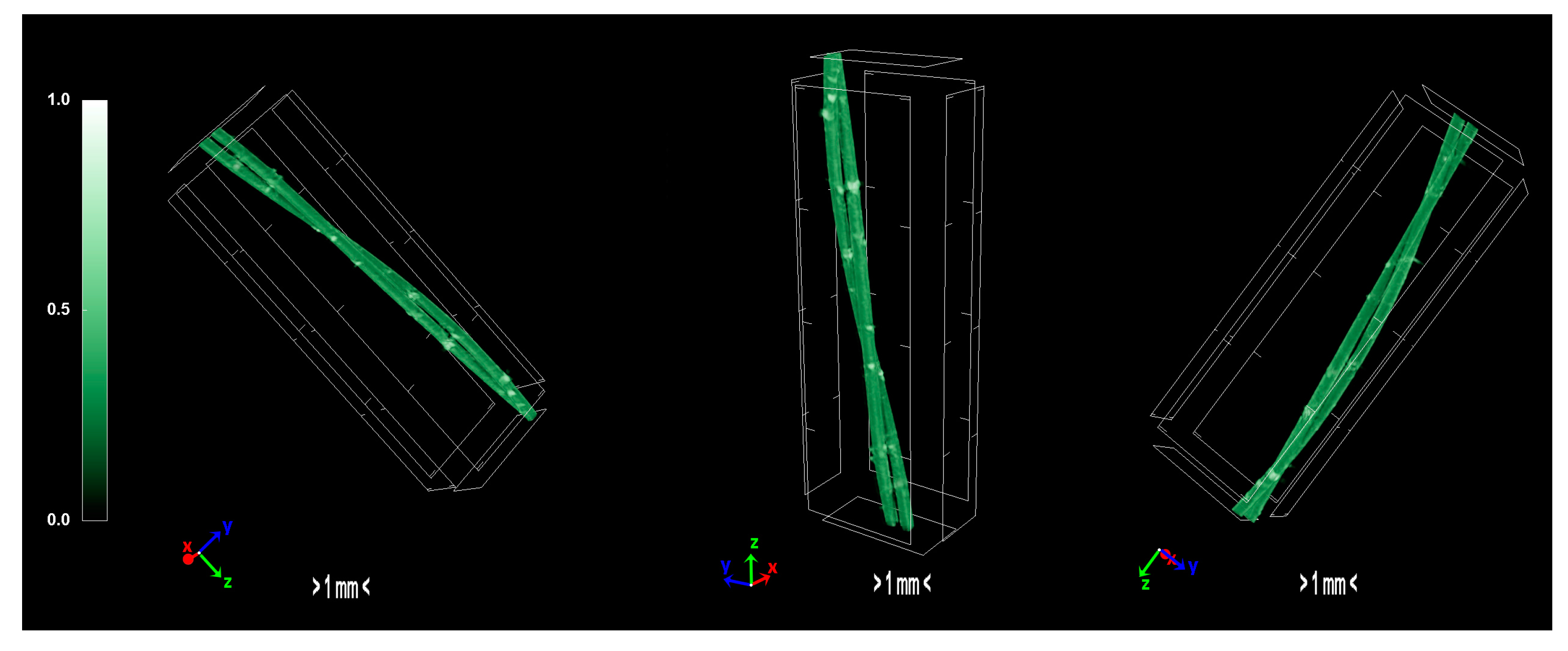
Figure 10.
Micro-CT images of the two-stage sulfonated HDPE/SKL (90:10) fibers.
Figure 10.
Micro-CT images of the two-stage sulfonated HDPE/SKL (90:10) fibers.
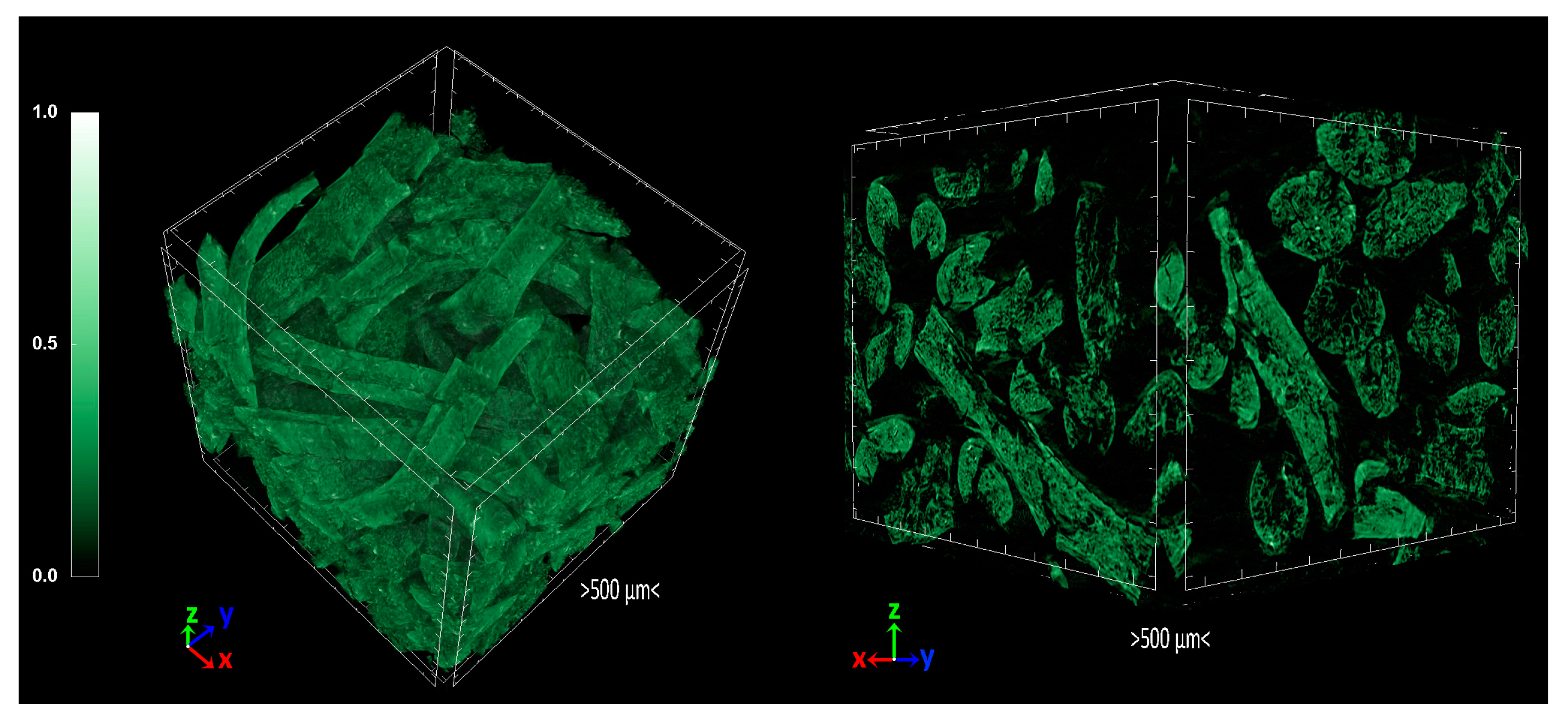
Figure 11.
3D volume rendering of the scanned carbon fibers.
Figure 11.
3D volume rendering of the scanned carbon fibers.
Figure 12.
Chemical reactions of HDPE/SKL (90:10) fiber sulfonation.
Figure 12.
Chemical reactions of HDPE/SKL (90:10) fiber sulfonation.
Figure 13.
Chemical reaction of desulfonation accompanied by crosslinking among the hydrocarbon polymers.
Figure 13.
Chemical reaction of desulfonation accompanied by crosslinking among the hydrocarbon polymers.
Figure 14.
Chemical reactions between hydrocarbon polymers and lignin.
Figure 14.
Chemical reactions between hydrocarbon polymers and lignin.
Table 1.
Tabulated values of wt % element concentration of the produced HDPE/SKL fibers.
Table 1.
Tabulated values of wt % element concentration of the produced HDPE/SKL fibers.
| Samples | C | O | S |
|---|
| Fiber untreated | 81.4 | 18.6 | - |
| Fiber-90 °C-1 h | 73.9 | 24.3 | 1.7 |
| Fiber-90 °C-3 h | 77.3 | 19.2 | 3.6 |
| Fiber-90 °C-5 h | 68.5 | 28.9 | 2.6 |
| Fiber-110 °C-1 h | 72.7 | 25.5 | 1.7 |
| Fiber-110 °C-3 h | 67.4 | 27.0 | 5.6 |
| Fiber-110 °C-5 h | 70.5 | 29.2 | 0.2 |
| Fiber-130 °C-1 h | 59.9 | 33.4 | 6.7 |
| Fiber-130 °C-3 h | 38.1 | 48.4 | 13.5 |
| Fiber-130 °C-5 h | 39.9 | 46.0 | 14.1 |
| Fiber-110 °C-3 h carbonized | 72.3 | 19.7 | 8.1 |
Table 2.
Identified ΑTR-FTIR peaks introduced by crosslinking due to the sulfonation reaction.
Table 2.
Identified ΑTR-FTIR peaks introduced by crosslinking due to the sulfonation reaction.
| Wavenumber (cm−1) | Bond Vibration |
|---|
| 3380 | O-H vibration in -OH groups and/or -COOH groups |
| 2921, 2848 | C-H stretching vibration |
| 2117 | Acetal from lignin |
| 1707 | carboxylic groups and/or unsaturated carbonyl groups |
| 1626 | C=C groups and conjugated C=C groups (or aromatics) |
| 1472 | CH2 binding |
| 1151 | S=O symmetrical stretch |
| 1035 | S=O asymmetrical stretch |
| 876 | S-O-C stretch, C-S deformation and =C-H wagging |
| 717 | C-C skeleton vibration |
| 583 | SO3 bending vibration, sulfate ion, C-C skeleton vibration |
| 526 | SO2 deformation and rocking vibration, =C-C-C in-plane bending |
| 457 | In-plane ring deformation vibrations |
Table 3.
Theoretical crosslinking index, γ (%), of sulfonated HDPE/SKL (90:10) fibers according to thermal analysis.
Table 3.
Theoretical crosslinking index, γ (%), of sulfonated HDPE/SKL (90:10) fibers according to thermal analysis.
| Sample | Cp (J/gK) | Tonset (°C) | Tin - Tfin (°C) | ΔΗm (J/g) | γ (%) |
|---|
| Fiber-90 °C-1 h | 5.7 | 306.7 | 270 - 333 | 134.9 | 20.0 |
| Fiber-90 °C-3 h | 162.9 | 367.7 | 363 - 374.9 | 53 | 68.6 |
| Fiber-90 °C-5 h | 18.6 | 376.4 | 373.4 - 413.1 | 49.7 | 70.5 |
| Fiber-110 °C-1 h | 332.6 | 377.2 | 373 - 384 | 67.6 | 59.9 |
| Fiber-110 °C-3 h | 5.1 | 324.6 | 303.1 - 326.3 | 61.6 | 63.5 |
| Fiber-110 °C-5 h | 261.1 | 352.5 | 347.9 - 360 | 91.8 | 45.6 |
| Fiber-130 °C-1 h | 29.2 | 388.1 | 383 - 421 | 71.1 | 57.9 |
| Fiber-130 °C-3 h | 171.5 | 370.1 | 367.7 - 375.2 | 78.1 | 53.7 |
| Fiber-130 °C-5 h | 253.7 | 397.2 | 393.1 - 404.1 | 67.04 | 60.3 |
| Fiber | 3.5 | 187.4 | 150 - 206.5 | 168.7 | (untreated) |
Table 4.
Micro-CT arithmetical values.
Table 4.
Micro-CT arithmetical values.
| Parameters | HDPE/SKL(90:10) Carbonized | HDPE/SKL(90:10) Sulfonated | HDPE/SKL(90:10) |
|---|
| Object Surface Density (mm−1) | 56.18 | 15.81 | 34.69 |
| Structure Linear Density (mm−1) | 14.71 | 4.727 | 7.874 |
| Structure Thickness (mm) | 0.062 | 0.210 | 0.126 |
| Degree of Anisotropy | 1.225 | 1.228 | 4.196 |
| Fractal Dimension | 2.663 | 1.798 | 1.825 |
| Object Surface to Volume ratio | 61.57 | 15.94 | 34.81 |
| Closed Porosity (%) | 0.287 | 0.481 | 0.325 |
| Open Porosity (%) | 8.487 | 0.320 | 0.249 |
| Total Porosity (%) | 8.774 | 0.801 | 0.574 |
Table 5.
Thermal oxidative stabilization experiments (stabilization apparatus).
Table 5.
Thermal oxidative stabilization experiments (stabilization apparatus).
| Material | 1st Stage | 2nd Stage | Applied Load (g) | Remarks |
|---|
| HDPE-SKL (90:10) | 100 °C, 5 h | ---* | 3 | Breakage during stabilization |
| HDPE-SKL (90:10) | 100 °C, 5 h | 130 °C, --- | 1 | Breakage during ramp from 100 °C to 130 °C |
| HDPE-SKL (90:10) | 100 °C, 5 h | --- | 3 | Rapid elongation until rupture |
Table 6.
Thermal stabilization experiments under atmosphere.
Table 6.
Thermal stabilization experiments under atmosphere.
| Material | 1st Stage | 2nd Stage | 3rd Stage | 4th Stage | Tension |
|---|
| HDPE/SKL (90:10) | 100 °C, 24 h | 145 °C, 24 h | 160 °C, 8 h | * | Yes |
| HDPE/SKL (90:10) | 100 °C, 5 h | 130 °C, 5 h | 160 °C, 5 h | 180 °C, 4 h | No |
Table 7.
Thermal stabilization experiments under argon atmosphere (flow rate 140 mL/min) without applied stress.
Table 7.
Thermal stabilization experiments under argon atmosphere (flow rate 140 mL/min) without applied stress.
| Material | 1st Stage | 2nd Stage | 3rd Stage | 4th Stage | 5th Stage |
|---|
| HDPE-SKL (90:10) | 125 °C, 1 h | 150 °C, 1 h | 180 °C, 1 h | 220 °C, 1 h | 260 °C, 2 h |
© 2017 by the authors. Licensee MDPI, Basel, Switzerland. This article is an open access article distributed under the terms and conditions of the Creative Commons Attribution (CC BY) license (http://creativecommons.org/licenses/by/4.0/).


 ,
, 


