Mechanical and Electrical Characterization of Carbon Fiber/Bucky Paper/Zinc Oxide Hybrid Composites

Department of Aerospace Engineering, Embry-Riddle Aeronautical University, Daytona Beach, FL 32114, USA
*
Author to whom correspondence should be addressed.
†
These authors contributed equally to this work.
C 2018, 4(1), 6; https://doi.org/10.3390/c4010006
Submission received: 1 December 2017
/
Revised: 9 January 2018
/
Accepted: 12 January 2018
/
Published: 18 January 2018
(This article belongs to the Special Issue Carbon Hybrid Materials)
Abstract
:The quest for multifunctional carbon fiber reinforced composites (CFRPs) expedited the use of several nano reinforcements such as zinc oxide nanorods (ZnO) and carbon nanotubes (CNTs). Zinc oxide is a semi-conductor with good piezoelectric and pyroelectric properties. These properties could be transmitted to CFRPs when a nanophase of ZnO is embedded within CFRPs. In lieu of ZnO nanorods, Bucky paper comprising mat of CNTs could be sandwiched in-between composite laminae to construct a functionally graded composite with enhanced electrical conductivities. In this study, different configurations of hybrid composites based on carbon fibers with different combinations of ZnO nanorods and Bucky paper were fabricated. The composites were tested mechanically via tensile and dynamic mechanical analysis (DMA) tests to examine the effect of the different nanoadditives on the stiffness, strength and the damping performance of the hybrid composites. Electrical resistivities of the hybrid composites were probed to examine the contributions of the different nanoadditives. The results suggest that there are certain hybrid composite combinations that could lead to the development of highly multifunctional composites with better strength, stiffness, damping and electrical conductivity.
1. Introduction
Structural carbon fiber-reinforced plastics (CFRPs) are utilized in applications where good fatigue resistance, elevated specific strength and stiffness are required. They also possess the appeals of high utilization factor and ease of formability. These qualities facilitated the use of CFRPs in various structures like aircrafts, automotives, civil infrastructures, marine and sporting goods. However, CFRPs have several drawbacks including insufficient through-thickness mechanical performance and lack of other functionalities such as sufficient electrical conductivity. A plethora of research has been devoted to improving the through-thickness properties of CFRPs [1,2]. Improvements were achieved via various routes such as stitching [1], braiding [3], fiber surface treatment [4], and interleaving with toughened polymers [5]. Recent studies have shown that utilizing nanomaterials such as nanoscale reinforcements [6,7] offers the opportunity to enrich the matrix-dependent properties of CFRPs with minimal weight penalty.
The extraordinary mechanical, electrical, and thermal properties of carbon nanotubes (CNTs) have motivated researches to utilize them as a filler phase in composite materials in order to improve the properties of the host matrix. The strength, elastic modulus and the fracture properties of CNTs are orders of magnitudes higher than common structural composites [8]. To exploit the remarkable properties of incorporating CNTs into CFRPs, hybrid carbon fiber/CNT reinforced polymer composites were developed [9]. However, the improper dispersion of CNTs in the matrix and their deagglomeration posed significant problems yet to be resolved. Alternatively, to eliminate the need for acceptable dispersion and deagglomeration, CNTs can be controlled and grown on the surfaces where they are needed. CNTs can be grown on most substrates such as silicon, silica, and alumina [10]. There are fewer reports discussing CNT growth on carbon materials; in particular yarns and fabrics [11]. Two major challenges encountered in CNT growth on carbon substrates are (i) transition metals (i.e., catalysts for CNTs’ synthesis) are easily diffused into the carbon substrates and; (ii) various morphologies of carbon materials are able to form on the graphite substrates because the growth conditions are similar to turbostartic carbon, graphite, and diamond or diamond-like carbon morphologies [12].
Catalytic chemical vapor deposition (CCVD) has been largely utilized to grow carbon nanofilaments on the surface of carbon fiber yarns with the aid of catalysts such as nickel, iron, cobalt and palladium at temperatures ranging from 700 to 1100 °C [10,13,14,15,16,17,18,19]. However, the temperature needed to grow CNTs via CCVD is rather high and is destructive to the substrate carbon fiber strength itself [20,21]. Zhang et al. [20], upon utilizing CVD (at 700–800 °C) to grow CNTs on PAN-based carbon fibers, reported that the strength of the T650 (Thornel®—Carbon fiber) declined by nearly 40% due to the exposure to elevated temperatures. Nevertheless, the interlaminar properties (i.e., interlaminar shear strength) of the composites containing CCVD grown CNTs was reported to improve [22,23].
Recently, Tehrani et al. [24] utilized graphitic structure by design (GSD) synthesis at relatively lower temperature (~500 °C) to grow MWCNTs over the surface of PAN-based carbon fibers. Compared to the carbon fiber/epoxy composite, results showed a slight decrease in the composite tensile strength (3.4%) and an improvement of Young’s modulus (8.2%). However, more pronounced enhancements were reported for the dynamic mechanical analysis (DMA) loss modulus (120%). Rather than growing individual patches of CNTs on carbon fibers, some investigators incorporated Bucky paper (BP) in-between CFRP laminae [25,26,27,28,29,30,31]. Bucky paper is a freestanding porous mat of entangled CNTs cohesively bound by van der Waals interactions. Bucky paper can be used to prepare polymer composites with uniform CNT dispersion and high CNT loading (up to 60 wt %) [32]. Besides its pronounced mechanical properties, BP is as conductive as copper and comparable to steel in heat dissipation. Incorporation of BP, as a ply layer in composites made of carbon fiber has the capacity to increase the overall mechanical and conductive properties of the resulting structure [26,33,34].
Zinc oxide (ZnO) is a material of high significance due to its combined piezoelectric, pyroelectric and semiconducting properties. These properties stem from the unique asymmetrical structure of wurtzite-like crystal, which also permits electromechanical coupling and high exciting band energy. Zinc oxide has a wide range of applications including optoelectronics, sensors, transducers and catalysis. Zinc oxide is known for various possible growth morphologies depending on the surface structure orientation chosen for the procedure. Growth is also controlled by various parameters like temperature, pressure, surface diffusion, time and other factors [35]. The different possible ZnO structures include nanocombs, nanobelts, branched hierarchical structures, nanohelixes, nanorods, and nanorings [35]. There are various methods to synthesize these nanostructures including vapor deposition methods, sol-gel, electrodeposition and low temperature hydrothermal growth methods [36,37,38,39]. The vapor deposition method is frequently employed for highly controlled and perfect nanostructures. However, this method requires expensive equipment, elevated temperatures, special substrates and source materials. Thus, the suitability of lower synthesis temperature for carbon fiber substrates justifies the selection of hydrothermal growth methods in the current study. Hung and Whang [37] proposed a low temperature growth technique for growth of single crystal ZnO nanorods on nanostructured substrates in two steps. First, sol-gel reaction is used to form uniform ZnO nanoparticle colloids with the reaction of cetyltrimethylammonium hydroxide (CTAOH) added to the stirred solution of zinc acetate and ethanol. Secondly, these colloids were dipped into heat-treated glass substrates. These substrates were then immersed in equimolar of zinc nitrate and methenamine aqueous solutions for 24 h at 90 °C to promote large scale nanorods growth of around 45 nm (in diameter). Literature suggests various ZnO catalyst seeding techniques are used in hydrothermal methods to grow ZnO nanorods. Some authors compared the resulting nanorods via two or more seeding techniques. One such study was carried out by Dong et al. [40], comparing results of dip coating and radio frequency (RF) magnetron sputtering on a silicon substrate. It was found that, unlike RF magnetron sputtering, the dip coating technique results in larger size distribution and surface roughness of the seed layer. In addition, the ZnO nanorods aligned perfectly normally to the substrate with uniform length in the sputtering method proving that this method has a clear advantage [9]. However, this method is expensive and unscalable for large composite structures. Hence, in the current study, a dip coating methodology was adopted.
Demes et al. [41] developed a model that describes the nanowire growth in relation to seed layer properties and growth duration. Mean grain size (MGS), surface coverage rate (SCR), and texture coefficients of the sol-gel procedure via grown ZnO nanowires are varied, in addition to various combinations of growth time and multilayer procedures to vary film thickness. The initial diameter of the nanowires was found to be 20 nm with approximate longitudinal and lateral growth rates of 25–30 and 0.01 nm/min, respectively. Akgun et al. [39], synthesized ZnO nanowires using zinc acetate dihydrate as a zinc salt as opposed to commonly used salts like zinc nitrate hexahydrate, zinc acetate and zinc chloride. The effects of parameters like time, temperature, solution concentration and concentration ratios of the precursor chemicals on the growth were studied. It was concluded that the diameter of the nanowires depends on the concentration of the precursor chemicals while their length is more likely to depend on the temperature and time involved during their growth. In addition, it was observed that this salt eliminates the usage of additional capping agents and results in formation of ZnO nanowires with comparatively less or no impurities.
Besides the seeding and zinc salts, other investigations revealed the effects of growth-promoting chemicals used in the aqueous bath for inducing the growth of nanorods. Though each chemical has its own significance, hexamethylenetetramine (HMTA) is of particular importance due to the pronounced role it plays. Strano et al. [42] probed the dual role of HMTA in the growth of ZnO nanorods in the chemical bath deposition growth method. It was noticed that in the presence of a lower amount of HMTA, the ZnO nanorods structures were not to be seen, confirming that HMTA bias growth along the c-axis and ensures vertical alignment of the grown ZnO nanorods. This was achieved through a steric hindrance effect, which results in inhibition of lateral growth. Furthermore, HMTA is a well-known pH regulator.
Like CNTs, ZnO nanorods can be grown on carbon fiber surfaces to enhance the interface between the fibers and the matrix. Unlike CNTs, despite their extraordinary physical properties, there are fewer reports on the effect of ZnO as interfacial reinforcement for CFRPs. Allington et al. [43] tested the shear strength of a single carbon fiber sheathed with ZnO nanowires (NWs) and reported 113% increase in the interfacial shear strength. Ehlert et al. [44] utilized identical ZnO growth process on aramid fiber and suggested that the carboxylic acid group is responsible for the good interfacial shear strength between the ZnO nanorods and the carbon fiber. More recently, Skandani et al. [9], reported 50% enhancement in the CFRPs loss modulus upon growing ZnO nanorods on the interface using RF magnetron sputtering for catalyst deposition. This improvement was attributed to the amplified interfacial area between the NWs and the epoxy matrix. However, such enhancement was accompanied with a slight decrease in the storage modulus (~7.0%).
While the individual effects of BP and ZnO nanorods on the electrical and mechanical performance of CFRP were probed by several published investigations, to the best of our knowledge, the combined effects of these nanofillers have not been investigated yet. Thus, the current study is carried out in an attempt of probing these effects. In the current work, various configurations of two-ply CFRPs composites incorporating different combinations of ZnO nanorods and Bucky paper are fabricated. These hybrid composites are characterized through tensile testing, dynamic mechanical analysis (DMA), fractography analysis and electrical conductivity testing.
2. Materials and Methods
2.1. Materials and Synthesis
Un-sized plain-woven carbon fiber fabric (IM7-GP, 6 K filaments count in a tow, provided by Hexcel Inc., Stamford, CT, USA) was used as the main reinforcements. Bucky Shield Grade 100% MWCNT (Buckeye Composites, Inc., Yadkinville, NC, USA) comprising MWCNTs with average thickness of 125 micron and density of 0.3–0.4 g/cm3 was used as BP in the current research.
2.1.1. Seeding of ZnO Catalyst
The dip-coating technique was utilized to apply the ZnO nanoparticles catalyst on the carbon fiber fabrics and Bucky paper, separately. Carbon fibers fabric and Bucky paper were coated with ZnO nanoparticles by dipping them directly in the seeding solution. The seeding solution comprised 164.6 mg of zinc acetate dihydrate dispersed in 150 mL of deionized (DI) water. 20 mL of ethanol was added to this mixture and then sonicated for 10 min using an ultrasonic processer to make a homogenized mixture. This solution was poured into a vessel of large surface area to dip the fibers of a particular cut size. Each time the samples were dipped, they were allowed to dry for 30 s and rinsed with ethanol. Finally, after the dipping procedure, the samples were heated at a temperature of 100 °C for 30 min to dry further. The number of dip coating were five and ten for the woven carbon fiber fabric and the Bucky paper, respectively.
2.1.2. Growth of ZnO Nanorods
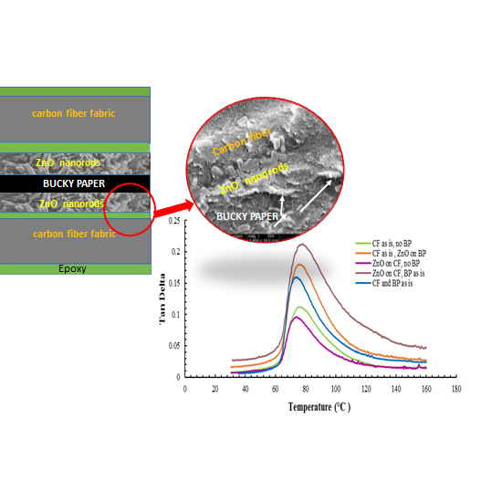
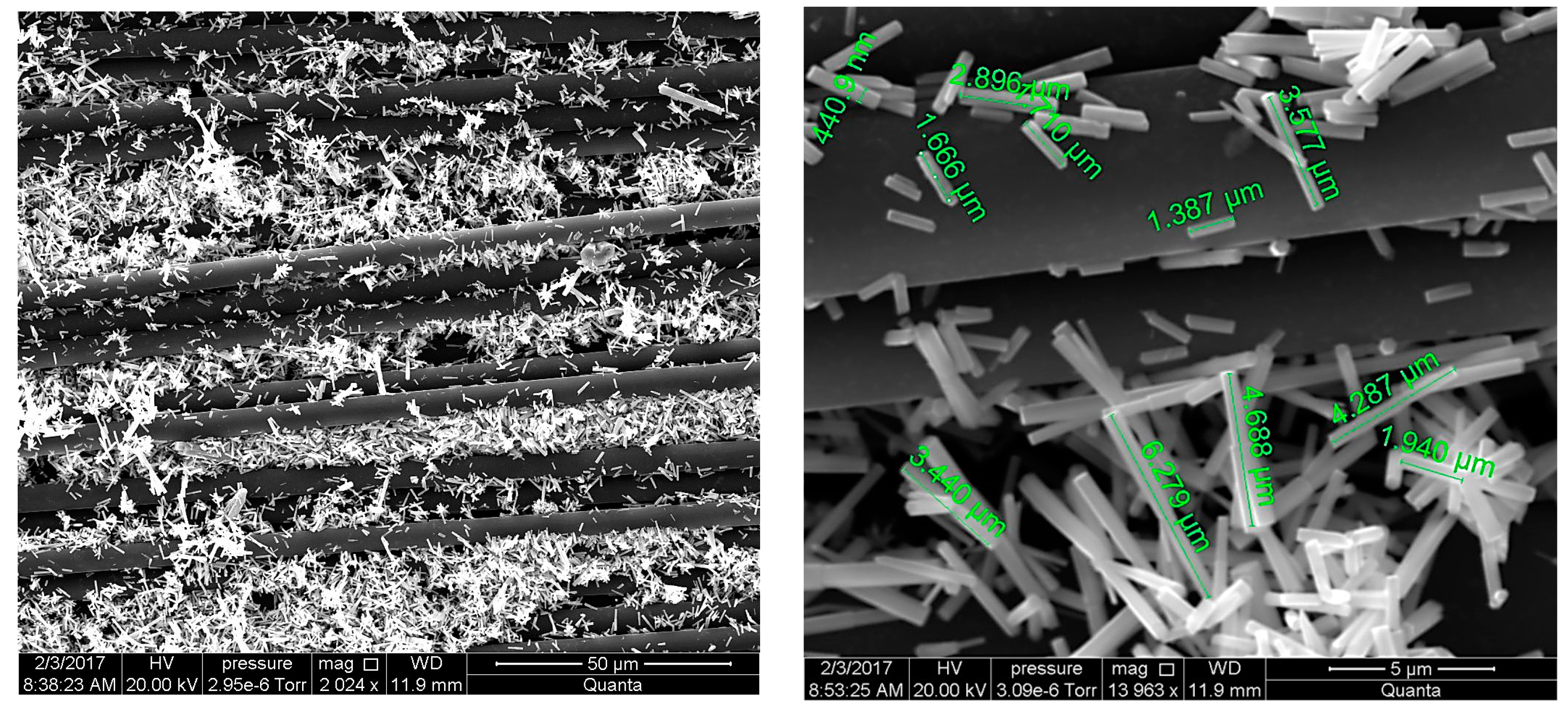
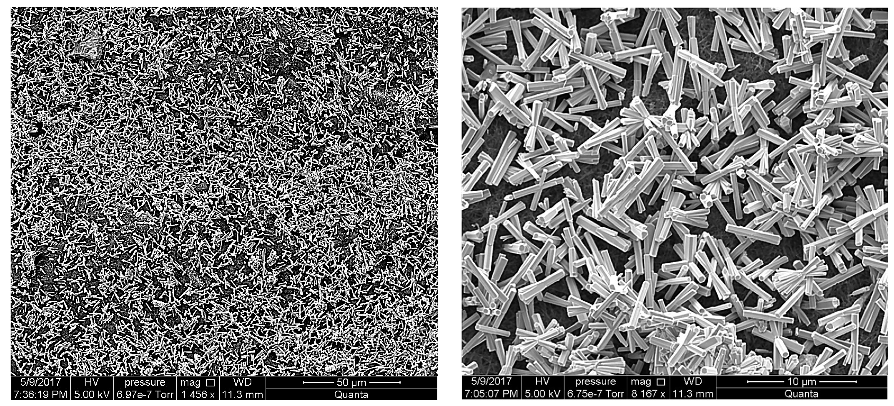
The chemical growth bath comprised 2.634 g of zinc acetate dehydrate (Alfa Aesar, Tewksbury, MA, USA) and 1.682 g of hexamethylenetetramine (HMTA, Alfa Aesar, Tewksbury, MA, USA) dispersed in 300 mL of DI water for each. The solutions were homogenized individually by mechanical sonication for 20 min each via a Vibra-Cell VCX 500 (Newtown, CT, USA) tip ultrasonic processor at amplitude 40%. Then the two solutions were mixed together and homogenized further via sonication for 10 min. The carbon fiber fabrics were immersed in the solution and placed inside a conduction furnace at a temperature of 90 °C for six hours. For the Bucky paper, the ZnO growth time was set to 4 h at 90 °C. Finally, the density of the nanorods growth, their length and diameter were observed using a FEI Quanta 650 scanning electron microscope (SEM, now Thermo-Fisher Scientific, Hillsboro, OR, USA) as shown in Figure 1 and Figure 2.
2.2. Composite Preparation
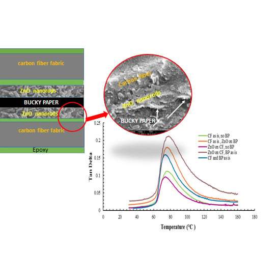
Five configurations of two-ply composites were fabricated: one with just carbon fiber (CF) as is, no Bucky paper, no ZnO (CF as is, no BP), second composite with carbon fiber, and nanorods on bucky paper (CF as is, ZnO on BP), a third composite with ZnO nanorods on carbon fiber, no Bucky paper (ZnO on CF, no BP), a fourth composite with nanorods on carbon fiber, Bucky paper as is (ZnO on CF, BP as is) and a fifth composite with both carbon fiber and Bucky paper as is (CF and BP as is). The chosen matrix material was Aeropoxy™ manufactured (PTM&W Industries, Inc., Santa Fe Springs, CA, USA). Aeropoxy comprises two components; PR2032 which is a Bisphenol-based resin with medium viscosity (1650 cps at room temperature), unfilled, light amber laminating resin that is designed for structural production applications. This resin, laminates very easily and wets out fiberglass, carbon and aramid fibers readily. The hardener is PH3660; a modified amine mixture with relatively low viscosity (190–200 cps at room temperature). When mixed together in the ratio 100:27 by weight the combined viscosity 800–875 cps and the glass transition temperature, Tg, is 91 °C. The authors utilized this epoxy system to manufacture both CFRPs [45,46] and nanocomposites based on SWCNT [47] and MWCNT [48]. The hand layup technique was utilized for laminating the composites; the Bucky paper (with or without ZnO nanorods on the surface) was interleaved between two carbon fiber fabrics upon impregnating them with epoxy, Figure 3. After hand lay-up, the composites were placed in a vacuum bag attached to a vacuum pump. The bag was pressed using a composite press (Wabash MPI, Wabash, IN, USA). The press maintained a pressure of (0.8 Torr) at 60 °C for two hours. Later the composites were left to cure for 24 h at room temperature.
2.3. Analysis
2.3.1. Tensile Testing
Abraded G-10 tabs were bonded to the ends of the tensile specimens using the same resin (i.e., Aeropoxy). The tensile test coupons of 12.5 cm × 1.25 cm were cut using a saw. The tensile tests were carried out following the ASTM-D3039 standard [49] utilizing a Tinius Olsen testing frame (Model 150STHorsham, PA, USA) under 1.0 mm/min constant crosshead speed. A Tinius Olsen extensometer (Horsham, PA, USA) with 2.54 cm gauge length was used to record the strain. The stress vs. strain data for different test coupons were recorded and analyzed in order to report the samples’ elastic moduli, ultimate strength and strain to failure. A minimum of 12 samples were tested for each composite configuration.
2.3.2. Fracture Analysis
After breaking the different composite samples during tensile testing, the fractured surface was handled with utmost care and mounted on the scanning electron microscope (SEM) sample holder. FEI Quanta 650 SEM was operated in a high vacuum mode with a tungsten thermionic gun for emitting electron beams, in this research. Also, a secondary electron detector (Everhart–Thornley Detector), with a positive bias to attract low energy secondary electrons was used for forming micrographs. Due to the low atomic number of the specimen, various problems arose in imaging at high magnifications. Thus, gold coating, proper accelerating voltage and ideal spot size for the current were various factors which decided the quality of the topographical information acquired. In fracture analysis, for each composite configuration, sample with high proximity to the average strength of a particular configuration was chosen. The samples were examined for the presence of fiber or matrix failure and possible defects. Micrographs at various magnifications were captured.
2.3.3. Dynamic Mechanical Analysis (DMA)
This test is used to find the elastic/viscoelastic behaviors of a given sample during the application of a sinusoidal force. The properties being measured for the purpose are tan (δ), storage modulus and loss modulus. The storage modulus, E’, is the measure of sample’s elastic nature. Tan (δ) is the ratio of loss (E”) to storage (E’) moduli. In addition, DMA can be used to measure the change in the glass temperature (Tg) of a material. In this study, a PerkinElmer DMA 8000 system (Waltham, MA, USA) was utilized. The DMA tests were carried out following the ASTM D4056-12 standard [50]. Samples of size (44.5 × 6.4 × 1.6 mm) were cut accordingly. Dual cantilever fixture was used to mount each of the composite samples. In the temperature sweep mode of the DMA, a constant frequency of 1 Hz was applied, while varying the temperature from 30 to 160 °C at a constant force and strain of 2 N and 0.03 mm, respectively. The frequency sweep test was performed with a frequency range from 1 to 100 Hz scanning at room temperature using the same force and strain applied in the temperature sweep test.
2.3.4. Electrical Resistivity Test
The electrical resistivity is a material property unlike the resistance. There are various types of resistivity which include surface resistivity, bulk resistivity and contact resistivity. The samples of each configuration were cut into a size following the ASTM-F43-99 standard [51]. Aluminum electrodes were glued to the samples using conductive silver epoxy, allowed to cure for 24 h at room temperature. The resistance was then measured between the two electrode ends. The sensitivity of the measured resistance was ± 0.05 Ω. Finally, the resistivity was calculated using the formula:
where is the resistivity in Ωm, R is resistance in ohms, A is area in m2 and L is separation length between the two electrodes in m.
3. Results and Discussion
3.1. Tensile Testing Results
Representative stress vs. strain curves for the designed CFRPs, obtained from the tension tests, are illustrated in Figure 4. The slope of the stress vs. strain curves of the CFRPs up to the strain value of 0.30% was considered as their apparent elastic moduli. The tensile strength of the designed CFRPs was considered the maximum stress value in the stress vs. strain data, and the strain to failure to be the strain value at the last data point of the curves. Once the strength and stiffness of each sample were calculated, the data were normalized accounting for the different volume fractions of fibers in various composite configurations. The average strength and stiffness for each composite configuration were calculated and presented in Figure 5 and Figure 6 and tabulated in Table 1.
Inferred from Figure 4, all the CFRPs showed initial linear-elastic behavior. However, as the load increases their behavior deviates from linearity due to initiation of matrix cracking and some individual fiber breakages. The cracks in the matrix could propagate towards the fibers increasing stress intensity close to the fibers causing fiber breakage. This was more apparent in the CFRPs with no ZnO nanorods; i.e., CF as is with no Bucky paper and CF and BP as is with no ZnO nanorods. Hence, the crack propagation could be stopped or deflected by the ZnO nanorods forest in the fiber/matrix interface region (such as the CFRPs with surface grown ZnO nanorods and CFRPs with ZnO grown on Bucky paper). In the case of individual fiber breakage, the stress transfer mechanism through the matrix in the fiber/matrix interface region aids the composite to withstand the load. The surface grown ZnO nanorods provide stronger fiber/matrix interface, thereby, help the hybrid CFRPs to resist the failure up to higher strains, and therefore to exhibit more ductile behavior than the CFRPs with no nano-reinforcements as can be seen in Figure 4. Hence, the samples with ZnO nanorods (with and without Bucky paper) exhibited enhancements in the strain to failure compared to the reference CFRPs by 27–45%, Figure 4.
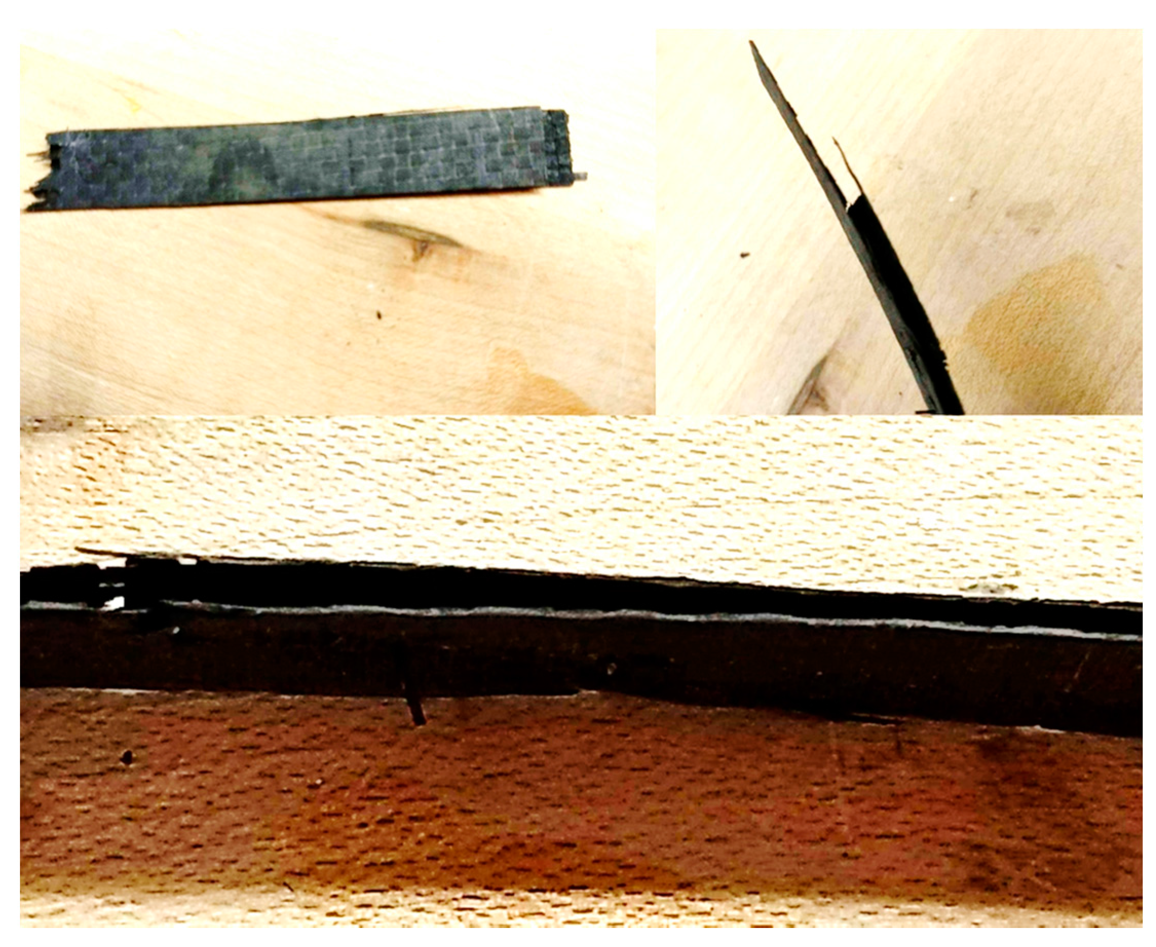
The strong fiber/matrix interface produced by randomly distributed ZnO nanorods in the samples where ZnO was grown directly on the carbon fiber with no Bucky paper presence improved the strength of the reference CFRPs by 20%, Figure 5. Growing ZnO on the surface of Bucky paper also yielded 23% improvement of the strength, suggesting that ZnO acts as a hurdle that assists reducing the delamination of the composite due to poor impregnation of the Bucky paper. An enhancement of 17% was also shown for a composite where the ZnO grown on the carbon fiber acts like an anchoring mechanism for Bucky paper setting on top of the ZnO forests. The only sample that exhibited a lower strength than the sample based on raw carbon fiber was the sample incorporating Bucky paper with no ZnO nanorods. As these samples lack the mechanism to resist stress propagation between the matrix and the surface of the Bucky paper (no pinning and no adhesion group between the matrix and the Bucky paper), the stress transfer easily detaches the Bucky paper from the surface of the fibers, leading to local delamination, Figure 7. Delamination failure has a negative effect on the final strength of the CFRPs.
Figure 6 suggests a slight increase 2.0–3.0% in the elastic moduli of the three configurations of CFRPs based on the fibers incorporating ZnO (grown either directly on the fibers or on Bucky paper). Incorporating Bucky paper without functionalizing in between carbon fibers yielded poor results in stiffness as the composite encountered early delamination during the test, which reduced the stiffness by 14%. Unfunctionalized Bucky papers are well known for poor impregnation of the epoxy especially in composite fabrication techniques employing pressure (i.e., composite press) vs. techniques employing vacuum (e.g., autoclave) [28]. To alleviate this shortcoming, some research groups utilized carboxyl group functionalization of Bucky paper which yielded structures with more favorable contact angles for epoxy composite processing [30]. In this investigation, we observed that the growth of ZnO on carbon fiber or on Bucky paper alleviates this delamination by inducing a pinning mechanism.
3.2. Fracture Analysis
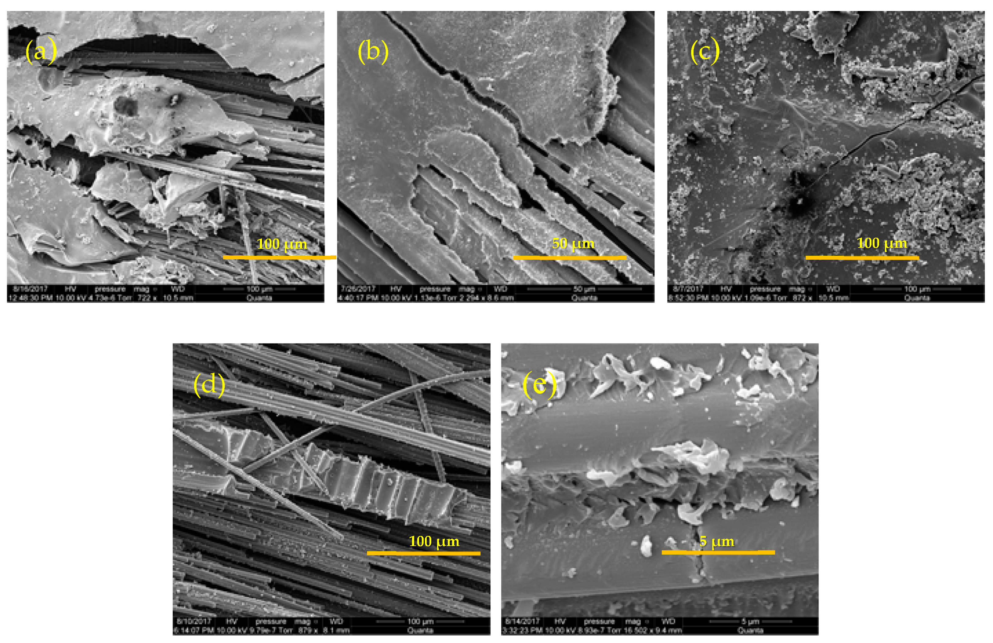
After the tensile test was performed, fracture analysis using the SEM was carried out. The sample with strength closer to the average strength of the respective configuration was chosen for analysis in each case. Once the sample was chosen, the area where the tensile test failure occurred was carefully severed and mounted under the SEM. In the case of delaminated samples, both split surfaces were analyzed to get a comprehensive idea of how failure occurred. The results are as shown in micrographs of Figure 8.
The micrographs show that the composite configurations lacking ZnO nanorods experienced both matrix and fiber fracture, while the hybrid composites incorporating ZnO nanorods have undergone a predominantly matrix fracture. Thus, the presence of nanorods reduces the chances of failure along the fiber, hence, increasing the overall strength and stiffness of the structure. The Bucky paper, though split due to delamination, remained continuous throughout. Thus, if the adhesion between various layers sandwiching the Bucky paper was better, the strength and stiffness could be enhanced.
3.3. DMA Results
3.3.1. Temperature Scan
The thermal DMA curves depicted in Figure 9 show variation of the loss tangent; tan (δ) with temperature.
In comparison to the composite based solely on carbon fibers, tan (δ) exhibited improvement when both ZnO nanorods and the Bucky paper coexisted in the composite. The composite with ZnO grown directly on the Bucky paper attained an increase of 61% in tan (δ) over the composite with no nanofillers. Improvements of 42–87% were observed for the different hybrid composites in comparison to the composite with no nanofillers, Table 2. The only configuration that exhibited lesser tan (δ); reduced by 16%, is associated with the sample with ZnO grown over the carbon fiber without Bucky paper. This observation can be attributed to the existence of moisture in their structure, most likely trapped between the nanorods, as this drop was not evident for the samples with no nano-reinforcements.
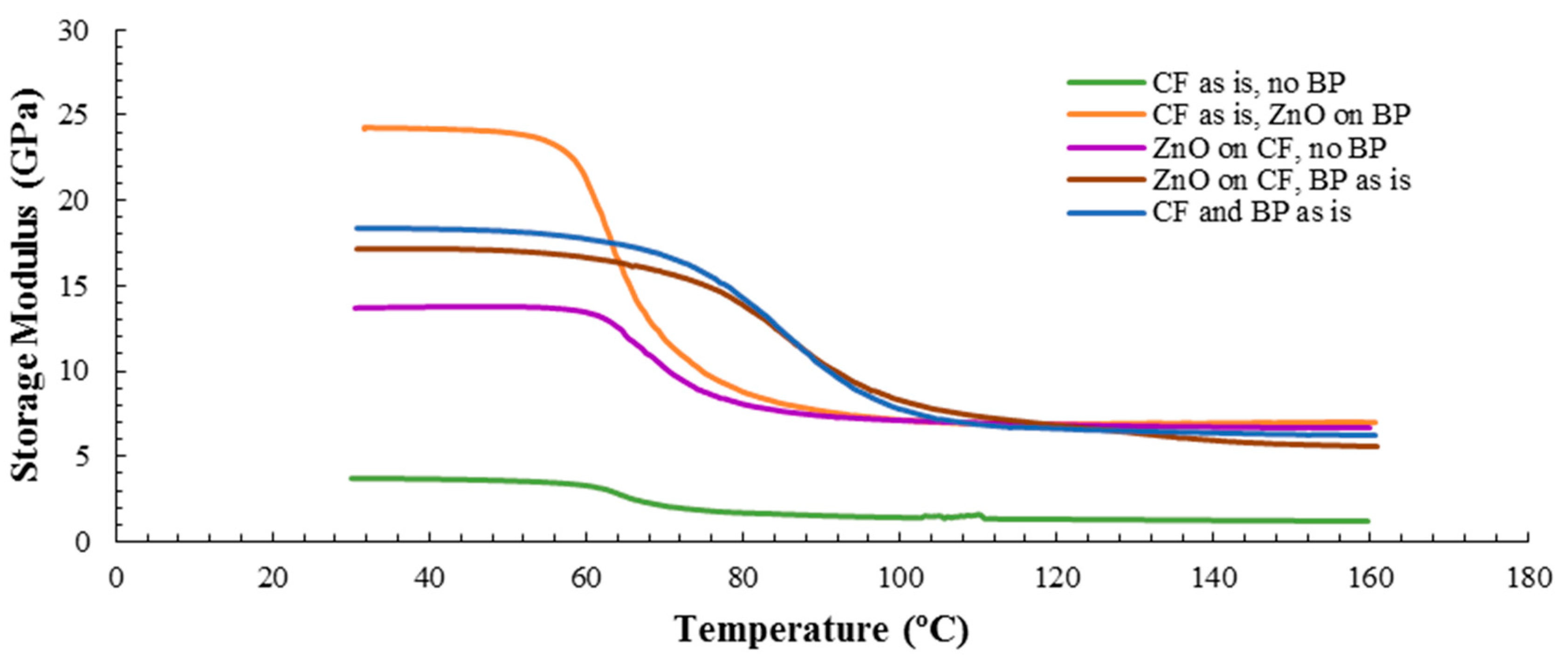
In Figure 10, at room temperature, the trend of the storage modulus is comparable to the tensile stiffness trend; composites with both ZnO and Bucky paper achieve higher storage modulus (310–536%) than the composite based on raw fibers, Table 2. The only exception is for the sample comprising carbon fiber and Bucky paper; as it did not delaminate under the low load of DMA test this sample showed a higher storage modulus than the composite based on the raw fiber while exhibiting lower stiffness in the tensile test due to premature delamination. As the temperature increases and passes through the glass transition temperature to the rubbery plateau, the storage moduli values drop significantly and beyond the glass transition, the difference between the composites with one or more nanofiller is negligible, Figure 10. However, the gap between storage moduli in the rubbery phase temperature range for all the composites with nanofillers are still higher than that for the composite based solely on carbon fibers. The storage modulus measured via DMA is not exactly the same as Young’s modulus of the classic stress-strain curve. Young’s modulus is the slope of a stress-strain curve in the initial linear region. In DMA, a storage modulus and an imaginary (loss) modulus are calculated from the material response to the sine wave. These different moduli allow better characterization of the material because we can now examine the ability of the material to retain energy or lose energy. Nevertheless, the storage modulus trend from DMA was consistent with that for quasi static tensile test except for one sample based on CFRP and Bucky paper, as this sample exhibited early delamination under tensile test while it stayed intact during DMA test due to applying much higher loads in the tensile test (several kN) compared to the minute load in DMA (2N).
It is worth noting that the glass transition temperature, Tg, can be found from either the first inflection point of the storage modulus curve or the peak of loss modulus, or the peak of tan (δ) curve. For the composites in this study, one can observe a difference within 20 °C between these methodologies by comparing the results in Figure 8 and Figure 9. This observation is in agreement with the results reported by Goertzen and Kessler [52]; for CFRP with highly cross-linked thermoset, the three DMA methods yield different values of Tg. Indeed, for thermosets, Menard [53] has shown that highly crossed thermosets have broad transition range and thus, when different DMA methodologies are utilized to find Tg, the results between the different methods may vary up to 25 °C. Hence, the most conservative method is to take Tg as the first inflection point while the least conservative method is the tan delta peak [54]. Following the most conservative method, one can observe from Figure 10 that most of the hybrid composites attained a high Tg than the composite based on carbon fibers alone. During glass transition, the epoxy molecular segments absorb heating energy and begin to move; however, the presence of nanofillers such as ZnO nanorods and Bucky paper diminishes the available space that would allow the molecular movement, thus more energy (and higher temperature) is needed to go around these hurdles.
3.3.2. Frequency Scan Results
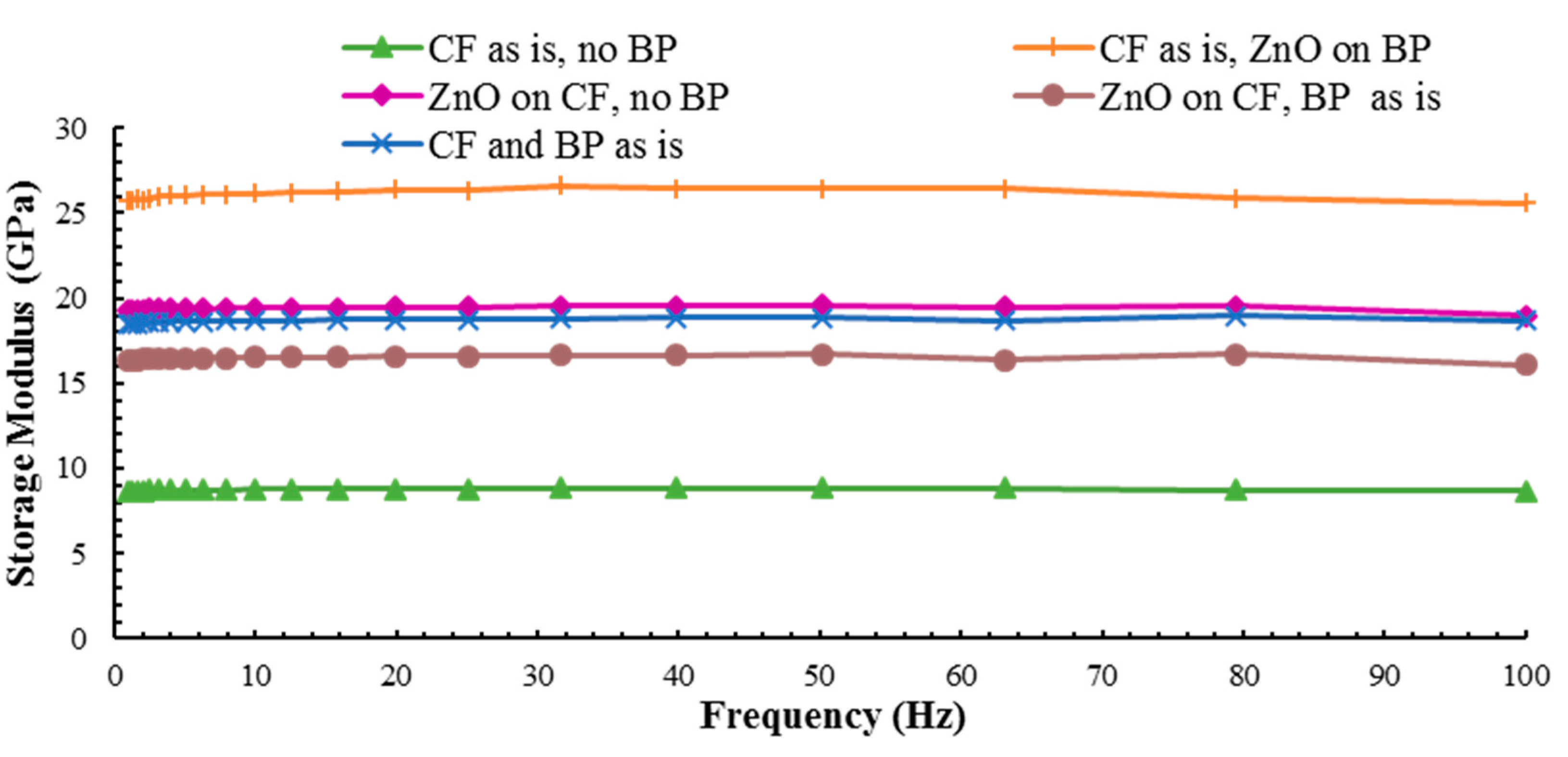
As shown in Figure 11, the storage moduli of the CFRPs were almost independent of the frequency. Unlike the storage modulus, loss tangent is highly dependent on the frequency, Figure 12, since this characteristic is driven by the viscoelastic behavior of the material. As evidenced by the results in Table 3, a composite that incorporates Bucky paper and ZnO nanorods attained the highest increase in tan (δ); an increase by 86%, followed by the composite that contains carbon fiber and Bucky paper (73% increase) and a composite with ZnO grown over the carbon fiber with Bucky paper in between the layers (23% increase). The mechanism responsible for the enhancement in damping can be the frictional slippage between the nanofillers and the epoxy matrix [9,55]. The outstanding energy dissipation through surface friction for the hybrid composite samples is due to the high surface area introduced by the high aspect ratio of the nanotubes and the nanowires into the CFRPs structure. This improvement is more pronounced for samples incorporating Bucky paper as they provide the largest interfacial area with the epoxy matrix.
The composite with ZnO only did not attain improvements in tan (δ) which, again, is attributed to insufficient drying of the fibers upon ZnO growth. This drop can also be attributed to the relative mobility of the nanowires inside the matrix when the Bucky paper is not surrounding the ZnO nanorods, which, despite enhancing the interfacial interaction, reduces the composite ability to dissipate mechanical energy through stick-slip mechanism.
The increase in tan (δ) demonstrates the combined capability of the Bucky paper and ZnO nanowires, as reinforcements, to promote the energy dissipation within the composite material. The epoxy matrix influences the energy dissipation in the composite more than the fibers due to the inherent viscoelastic nature of the polymeric matrix. Besides the matrix contribution, vibrational energy can be dissipated through slippage and frictional interactions between the nano-reinforcement and the matrix. The small size nanowires and the MWCNTs in the Bucky paper yield large reinforcement-matrix interface, thereby enhancing the energy dissipation due to interfacial friction during vibration.
The trend for the storage modulus at 30 °C, which is indicative of the viscoelastic stiffness, is shown in Figure 11. The composite incorporating ZnO nanowires on Bucky paper exhibited 200% increase in the storage modules compared to the baseline composite with no nanofillers. All the composites with one or two nanofillers showed improvements of at least 90% over the composite based on CF only. It is worth noting that unlike tan (δ), the storage modulus shows little variation over the frequency range. The same frequency-dependent pattern was observed for all the different composite configurations.
Upon comparing the results of storage modulus and tan (δ) obtained under isothermal conditions and varying frequency to those obtained under fixed frequency and temperature scan, there is a slight change in the trends. Nevertheless, the general trend is that composites based on CFRPs and two nanofillers obtain better storage moduli and damping parameters. The variations in the trends could be attributed to the fact that during the temperature scan, the thermoset epoxy will continue to cure (polymerize) with the added heat. Hence, some samples, if not fully cured prior to the temperature scan test, will undergo further curing that could change the microstructure/properties of the epoxy compared to the samples that have not encountered thermal heating during the frequency scan. Thus, both the frequency and temperature affects the DMA results. The effect of frequency on the dynamic mechanical response of thermosets is well documented. An increase in test frequency under isothermal conditions will shift the peak of the tan (δ) curve to a higher temperature [4,5,6]. This phenomenon is based on the Arrhenius fundamental relationships between temperature and the frequency of molecular conformational changes in polymers [7].
3.4. Surface Resistivity Results
To quantify the improvements of the electrical conductivity, the surface electrical resistivity was measured along the in-plane direction. The results were normalized by the surface area as illustrated in Table 4.
In comparison to the baseline composite with no nanofillers, the sample with the highest conductivity (or least resistivity) was the sample with just carbon fiber and Bucky paper. This sample exhibited 80% improvements in conductivity followed by the samples that have ZnO grown over Bucky paper sandwiched between the two laminae (increased by 76%) and the sample with ZnO on Carbon fiber with a layer of Bucky paper in between them (73%). These results highlight the pronounced role of Bucky paper as a conductive phase compared to that for ZnO nanorods, which is a semiconductor phase. Nevertheless, the sample based on ZnO also exhibited a 70% decrease in resistivity. Hence, one concludes that the presence of a nanophase such as MWCNTs (in Bucky paper) or ZnO nanowires or both assists in forming continuous conductive pathways, which translates to better conductivity.
4. Conclusions
This work is an attempt to fabricate a new hybrid composite with optimal combination of Bucky paper, ZnO nanowires and carbon fiber toward achieving multifunctionality while improving the mechanical and electrical properties of CFRPs. Zinc oxide nanorods were grown on carbon fibers utilizing a low temperature hydrothermal synthesis procedure. Other nanofillers comprised MWCNTs in the form of Bucky paper. It was concluded that unfunctionalized Bucky paper is prone to delamination resulting in a significant decrease in the strength and stiffness of CFRPs based on neat carbon fibers. In composites incorporating ZnO nanorods, the nanorods act as pinning hurdles, resisting crack propagation and, thus, assist the composite to withstand higher loads. Moreover, the CFRPs with ZnO grown either on Bucky paper or on carbon fibers possessed more ductility coupled with enhanced strength and stiffness. The largest enhancement in stiffness was in samples with ZnO grown over carbon fibers and Bucky paper sandwiched between the two plies. The most noticeable enhancement in strength was displayed by the composite based on ZnO nanorods grown on Bucky paper and sandwiched between the carbon fiber plies. Fractography analysis revealed that samples with nanofillers showed predominant matrix failure, while the other samples showed both matrix and fiber failure.
It is concluded that most of the hybrid composites attain a higher Tg than the composite based on carbon fibers alone. The presence of nanofillers reduces the space available for molecular movement, thus, more energy (and higher temperature) is needed to overcome these hurdles resulting in a higher Tg. DMA analysis showed an increase in tan (δ) for all composite configurations with one or more nanofillers expect for the one configuration where insufficient drying of the sample yielded a drop in tan (δ). The sample with carbon fiber and Bucky paper showed higher storage modulus in comparison to raw composite as DMA loading was not high enough to cause premature delamination. Enhancement in tan (δ) could be attributed to the promotion of energy dissipation, resulting from the large interfaces furnished by the presence of both MWCNTs in Bucky paper and ZnO nanowires. Both the storage modulus and tan (δ) exhibited pronounced enhancement over the frequency range. The most pronounced enhancements in the storage modulus and tan (δ) were achieved by the sample based on ZnO nanorods grown on Bucky paper and placed in between carbon fibers plies. The electrical conductivity for that sample was improved the most as well over all the other samples.
In conclusion, the results suggest that hybrid composites incorporating two nanofillers, ZnO nanorods and Bucky paper, achieve overall better enhancements in strength, modulus damping and electrical resistivity in comparison to composites with no nanofillers or single nanofiller.
Acknowledgments
Marwan Al-Haik gratefully acknowledges the support from Embry-Riddle Aeronautical University Accelerated Research Imitative (ARI) grant. Virginie Rollin acknowledges the NSF support through Award # NSF-DMR-1337742.
Author Contributions
Suma Ayyagari carried out the growth of ZnO nanorods and manufacturing and mechanical/electrical characterization of the hybrid composites. Virginie Rollin assisted in the development of micrographs via electron scan microscopy. Marwan Al-Haik guided this research, he developed the technique for growth of ZnO on carbon fibers and assisted in manufacturing and characterization of the hybrid composites.
Conflicts of Interest
The authors declare no conflict of interest.
References
- Trabelsi, W.; Michel, L.; Othomene, R. Effects of stitching on delamination of satin weave carbon-epoxy laminates under mode I, mode II and mixed-mode I/II loadings. Appl. Compos. Mater. 2010, 17, 575–595. [Google Scholar] [CrossRef] [Green Version]
- Khan, S.U.; Kim, J.-K. Impact and Delamination Failure of Multiscale Carbon Nanotube-Fiber Reinforced Polymer Composites: A Review. Int. J. Aeronaut. Space Sci. 2011, 12, 115–133. [Google Scholar] [CrossRef]
- Gu, B.H.; Li, Y.L. Ballistic perforation of conically cylindrical steel projectile into three-dimensional braided composites. Aiaa J. 2005, 43, 426–434. [Google Scholar] [CrossRef]
- Chung, D.D.L. Structural composite materials tailored for damping. J. Alloys Compd. 2003, 355, 216–223. [Google Scholar] [CrossRef]
- Aksoy, A.; Carlsson, L. Interlaminar shear fracture of interleaved graphite/epoxy composites. Compos. Sci. Technol. 1992, 43, 55–69. [Google Scholar] [CrossRef]
- Vlasveld, D.P.N.; Bersee, H.E.N.; Picken, S.J. Nanocomposite matrix for increased fibre composite strength. Polymer 2005, 46, 10269–10278. [Google Scholar] [CrossRef]
- Hudnut, S.W.; Chung, D.D.L. Use of submicron diameter carbon filaments for reinforcement between continuous carbon-fiber layers in a polymer-matrix composite. Carbon 1995, 33, 1627–1631. [Google Scholar] [CrossRef]
- Thostenson, E.T.; Chou, T.-W. Aligned multi-walled carbon nanotube-reinforced composites: Processing and mechanical characterization. J. Phys. D 2002, 35, L77. [Google Scholar] [CrossRef]
- Alipour Skandani, A.; Masghouni, N.; Case, S.W.; Leo, D.J.; Al-Haik, M. Enhanced vibration damping of carbon fibers-ZnO nanorods hybrid composites. Appl. Phys. Lett. 2012, 101, 073111. [Google Scholar] [CrossRef]
- Garcia, E.; Wardle, B.; deVilloria, R.; Guzman de Villoria, R.; Wicks, S.; Ishiguro, K.; Yamamoto, N.; Hart, A. Aligned Carbon Nanotube Reinforcement of Advanced Composite Ply Interfaces. In 49th AIAA/ASME/ASCE/AHS/ASC Structures, Structural Dynamics, and Materials Conference, 16th AIAA/ASME/AHS Adaptive Structures Conference,10th AIAA Non-Deterministic Approaches Conference, 9th AIAA Gossamer Spacecraft Forum, 4th AIAA Multidisciplinary Design Optimization Specialists Conference; American Institute of Aeronautics and Astronautics: Reston, VA, USA, 2008. [Google Scholar]
- Otsuka, K.; Abe, Y.; Kanai, N.; Kobayashi, Y.; Takenaka, S.; Tanabe, E. Synthesis of carbon nanotubes on Ni/carbon-fiber catalysts under mild conditions. Carbon 2004, 42, 727–736. [Google Scholar] [CrossRef]
- Zhu, S.; Su, C.-H.; Lehoczky, S.L.; Muntele, I.; Ila, D. Carbon nanotube growth on carbon fibers. Diam. Relat. Mater. 2003, 12, 1825–1828. [Google Scholar] [CrossRef]
- Sinnott, S.B.; Andrews, R. Carbon Nanotubes: Synthesis, Properties, and Applications. Crit. Rev. Solid State Mater. Sci. 2001, 26, 145–249. [Google Scholar] [CrossRef]
- Gibson, R.F. A review of recent research on mechanics of multifunctional composite materials and structures. Compos. Struct. 2010, 92, 2793–2810. [Google Scholar] [CrossRef]
- Luhrs, C.C.; Garcia, D.; Tehrani, M.; Al-Haik, M.; Taha, M.R.; Phillips, J. Generation of carbon nanofilaments on carbon fibers at 550 °C. Carbon 2009, 47, 3071–3078. [Google Scholar] [CrossRef]
- Al-Haik, M.; Luhrs, C.C.; Reda Taha, M.M.; Roy, A.K.; Dai, L.; Phillips, J.; Doorn, S. Hybrid Carbon Fibers/Carbon Nanotubes Structures for Next Generation Polymeric Composites. J. Nanotechnol. 2010, 2010, 860178. [Google Scholar] [CrossRef]
- Boskovic, B.O.; Golovko, V.B.; Cantoro, M.; Kleinsorge, B.; Chuang, A.T.H.; Ducati, C.; Hofmann, S.; Robertson, J.; Johnson, B.F.G. Low temperature synthesis of carbon nanofibres on carbon fibre matrices. Carbon 2005, 43, 2643–2648. [Google Scholar] [CrossRef]
- Phillips, J.; Leseman, Z.C.; Cordaro, J.; Luhrs, C.; Al-Haik, M. Novel Graphitic Structures by Design. In Proceedings of the ASME 2007 International Mechanical Engineering Congress and Exposition, Volume 13: Processing and Engineering Applications of Novel Materials, Seattle, WA, USA, 11–15 November 2007; pp. 177–179. [Google Scholar]
- Chen, X.; Saito, T.; Kusunoki, M.; Motojima, S. Three-dimensional vapor growth mechanism of carbon microcoils. J. Mater. Res. 2011, 14, 4329–4336. [Google Scholar] [CrossRef]
- Zhang, Q.; Liu, J.; Sager, R.; Dai, L.; Baur, J. Hierarchical composites of carbon nanotubes on carbon fiber: Influence of growth condition on fiber tensile properties. Compos. Sci. Technol. 2009, 69, 594–601. [Google Scholar] [CrossRef]
- Westwood, M.E.; Webster, J.D.; Day, R.J.; Hayes, F.H.; Taylor, R. Oxidation protection for carbon fibre composites. J. Mater. Sci. 1996, 31, 1389–1397. [Google Scholar] [CrossRef]
- Askari, D.; Ghasemi-Nejhad, M.N. Inter-Laminar Mechanical Properties Improvements in Carbon Nanotubes Reinforced Laminated Nanocomposites. In Proceedings of the ASME 2011 International Mechanical Engineering Congress and Exposition, Volume 8: Mechanics of Solids, Structures and Fluids; Vibration, Acoustics and Wave Propagation, Denver, CO, USA, 11–17 November 2011; pp. 533–538. [Google Scholar]
- Wicks, S.S.; de Villoria, R.G.; Wardle, B.L. Interlaminar and intralaminar reinforcement of composite laminates with aligned carbon nanotubes. Compos. Sci. Technol. 2010, 70, 20–28. [Google Scholar] [CrossRef]
- Tehrani, M.; Safdari, M.; Boroujeni, A.Y.; Razavi, Z.; Case, S.W.; Dahmen, K.; Garmestani, H.; Al-Haik, M.S. Hybrid carbon fiber/carbon nanotube composites for structural damping applications. Nanotechnology 2013, 24, 155704. [Google Scholar] [CrossRef] [PubMed]
- Li, M.; Wang, Z.Z.; Liu, Q.L.; Wang, S.K.; Gu, Y.Z.; Li, Y.X.; Zhang, Z.G. Carbon Nanotube Film/Epoxy Composites With High Strength and Toughness. Polym. Compos. 2017, 38, 588–596. [Google Scholar] [CrossRef]
- Liu, W.; Wei, B.C.; Xu, F.J. Investigation on the mechanical and electrical properties of carbon nanotube/epoxy composites produced by resin transfer molding. J. Compos. Mater. 2017, 51, 2035–2043. [Google Scholar] [CrossRef]
- Shin, Y.C.; Novin, E.; Kim, H. Electrical and Thermal Conductivities of Carbon Fiber Composites with High Concentrations of Carbon Nanotubes. Int. J. Precis. Eng. Manuf. 2015, 16, 465–470. [Google Scholar] [CrossRef]
- Ashrafi, B.; Guan, J.; Mirjalili, V.; Hubert, P.; Simard, B.; Johnston, A. Correlation between Young’s Modulus and Impregnation Quality of Epoxy-Impregnated SWCNT Buckypaper. Compos. Part A Appl. Sci. Manuf. 2010, 41, 1184–1191. [Google Scholar] [CrossRef]
- Jakubinek, M.B.; Ashrafi, B.; Guan, J.; Johnson, M.B.; White, M.A.; Simard, B. 3D chemically cross-linked single-walled carbon nanotube buckypapers. RSC Adv. 2014, 4, 57564–57573. [Google Scholar] [CrossRef]
- Lopes, P.E.; van Hattum, F.; Pereira, C.M.C.; Nóvoa, P.J.R.O.; Forero, S.; Hepp, F.; Pambaguian, L. High CNT content composites with CNT Buckypaper and epoxy resin matrix: Impregnation behaviour composite production and characterization. Compos. Struct. 2010, 92, 1291–1298. [Google Scholar] [CrossRef]
- Ribeiro, B.; Botelho, E.C.; Costa, M.L.; Bandeira, C.F. Carbon nanotube buckypaper reinforced polymer composites: A review. Polimeros 2017, 27, 247–255. [Google Scholar] [CrossRef]
- Pham, G.T.; Park, Y.B.; Wang, S.R.; Liang, Z.Y.; Wang, B.; Zhang, C.; Funchess, P.; Kramer, L. Mechanical and electrical properties of polycarbonate nanotube buckypaper composite sheets. Nanotechnology 2008, 19, 325705. [Google Scholar] [CrossRef] [PubMed]
- Han, J.H.; Zhang, H.; Chen, M.J.; Wang, G.R.; Zhang, Z. CNT buckypaper/thermoplastic polyurethane composites with enhanced stiffness, strength and toughness. Compos. Sci. Technol. 2014, 103, 63–71. [Google Scholar] [CrossRef]
- Yang, S.Y.; Ma, C.C.M.; Teng, C.C.; Huang, Y.W.; Liao, S.H.; Huang, Y.L.; Tien, H.W.; Lee, T.M.; Chiou, K.C. Effect of functionalized carbon nanotubes on the thermal conductivity of epoxy composites. Carbon 2010, 48, 592–603. [Google Scholar] [CrossRef]
- Ma, Q.; Wang, Y.; Kong, J.; Jia, H.; Wang, Z. Controllable synthesis of hierarchical flower-like ZnO nanostructures assembled by nanosheets and its optical properties. Superlattices Microstruct. 2015, 84, 1–12. [Google Scholar] [CrossRef]
- Byrne, D.; McGlynn, E.; Cullen, J.; Henry, M.O. A catalyst-free and facile route to periodically ordered and c-axis aligned ZnO nanorod arrays on diverse substrates. Nanoscale 2011, 3, 1675–1682. [Google Scholar] [CrossRef] [PubMed] [Green Version]
- Hung, C.H.; Whang, W.T. A novel low-temperature growth and characterization of single crystal ZnO nanorods. Mater. Chem. Phys. 2003, 82, 705–710. [Google Scholar] [CrossRef]
- Liu, J.; Chang, M.-J.; Du, H.-L. Controllable growth of highly organized ZnO nanowires using templates of electrospun nanofibers. J. Mater. Sci. Mater. Electron. 2016, 27, 7124–7131. [Google Scholar] [CrossRef]
- Akgun, M.C.; Kalay, Y.E.; Unalan, H.E. Hydrothermal zinc oxide nanowire growth using zinc acetate dihydrate salt. J. Mater. Res. 2012, 27, 1445–1451. [Google Scholar] [CrossRef]
- Dong, J.J.; Zhen, C.Y.; Hao, H.Y.; Xing, J.; Zhang, Z.L.; Zheng, Z.Y.; Zhang, X.W. Controllable synthesis of ZnO nanostructures on the Si substrate by a hydrothermal route. Nanoscale Res. Lett. 2013, 8, 378. [Google Scholar] [CrossRef] [PubMed]
- Demes, T.; Ternon, C.; Riassetto, D.; Stambouli, V.; Langlet, M. Comprehensive study of hydrothermally grown ZnO nanowires. J. Mater. Sci. 2016, 51, 10652–10661. [Google Scholar] [CrossRef]
- Strano, V.; Urso, R.G.; Scuderi, M.; Iwu, K.O.; Simone, F.; Ciliberto, E.; Spinella, C.; Mirabella, S. Double Role of HMTA in ZnO Nanorods Grown by Chemical Bath Deposition. J. Phys. Chem. C 2014, 118, 28189–28195. [Google Scholar] [CrossRef]
- Allington, R.D.; Attwood, D.; Hamerton, I.; Hay, J.N.; Howlin, B.J. A model of the surface of oxidatively treated carbon fibre based on calculations of adsorption interactions with small molecules. Compos. Part A Appl. Sci. Manuf. 1998, 29, 1283–1290. [Google Scholar] [CrossRef]
- Ehlert, G.J.; Sodano, H.A. Zinc Oxide Nanowire Interphase for Enhanced Interfacial Strength in Lightweight Polymer Fiber Composites. ACS Appl. Mater. Interfaces 2009, 1, 1827–1833. [Google Scholar] [CrossRef] [PubMed]
- Al-Haik, M.S.; Garmestani, H.; Savran, A. Explicit and implicit viscoplastic models for polymeric composite. Int. J. Plast. 2004, 20, 1875–1907. [Google Scholar] [CrossRef]
- Al-Haik, M.S.; Hussaini, M.Y.; Garmestani, H. Prediction of nonlinear viscoelastic behavior of polymeric composites using an artificial neural network. Int. J. Plast. 2006, 22, 1367–1392. [Google Scholar] [CrossRef]
- Garmestani, H.; Al-Haik, M.S.; Dahmen, K.; Tannenbaum, R.; Li, D.; Sablin, S.S.; Hussaini, M.Y. Polymer-Mediated Alignment of Carbon Nanotubes under High Magnetic Fields. Adv. Mater. 2003, 15, 1918–1921. [Google Scholar] [CrossRef]
- Tehrani, M.; Safdari, M.; Al-Haik, M.S. Nanocharacterization of creep behavior of multiwall carbon nanotubes/epoxy nanocomposite. Int. J. Plast. 2011, 27, 887–901. [Google Scholar] [CrossRef]
- ASTM Committee D30 on Composite Materials. Standard Test Method for Tensile Properties of Polymer Matrix Composite Materials; D3039/D3039M-17; ASTM International: West Conshohocken, PA, USA, 2017. [Google Scholar]
- ASTM Committee D30 on Composite Materials. Standard Test Method for Tensile Properties of Polymer Matrix Composite Materials; D4056-12; ASTM International: West Conshohocken, PA, USA, 2017. [Google Scholar]
- ASTM Committee F-1 on Electronics. Standard Test Methods for Resistivity of Semiconductor Materials; F43-99; STM International: West Conshohocken, PA, USA, 1999. [Google Scholar]
- Goertzen, W.K.; Kessler, M.R. Dynamic mechanical analysis of carbon/epoxy composites for structural pipeline repair. Compos. Part B 2007, 38, 1–9. [Google Scholar] [CrossRef]
- Menard, K.P. Dynamic Mechanical Analysis: A Practical Introduction, 2nd ed.; CRC Press: Boca Raton, FL, USA, 2008. [Google Scholar]
- Li, G.; Lee-Sullivan, P.; Thring, R.W. Determination of Activation Energy for Glass Transition of an Epoxy Adhesive Using Dynamic Mechanical Analysis. J. Therm. Anal. Calorim. 2000, 60, 377–390. [Google Scholar] [CrossRef]
- Sumita, M.; Gohda, H.; Asai, S.; Miyasaka, K.; Furuta, A.; Suzuki, Y.; Uchino, K. New damping materials composed of piezoelectric and electro-conductive, particle-filled polymer composites: Effect of the electromechanical coupling factor. Makromol. Chem. Rapid Commun. 1991, 12, 657–661. [Google Scholar] [CrossRef]
Figure 1.
ZnO nanorods grown on carbon fiber substrate at different magnifications.

Figure 2.
ZnO nanorods grown on Bucky paper substrate at different magnifications.

Figure 3.
Schematic of the architecture of hand layup of a composite comprising carbon fibers and Bucky paper with surface grown ZnO nanorods
Figure 3.
Schematic of the architecture of hand layup of a composite comprising carbon fibers and Bucky paper with surface grown ZnO nanorods
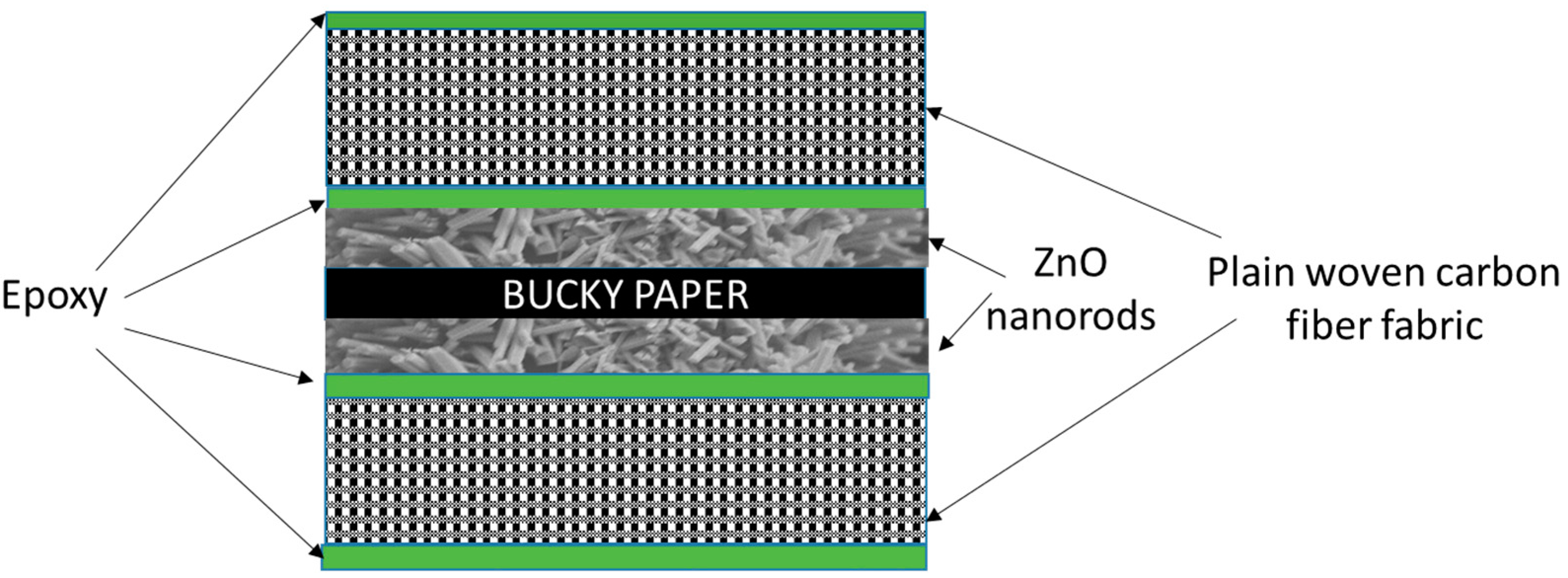
Figure 4.
Comparison of tensile test data of various configurations
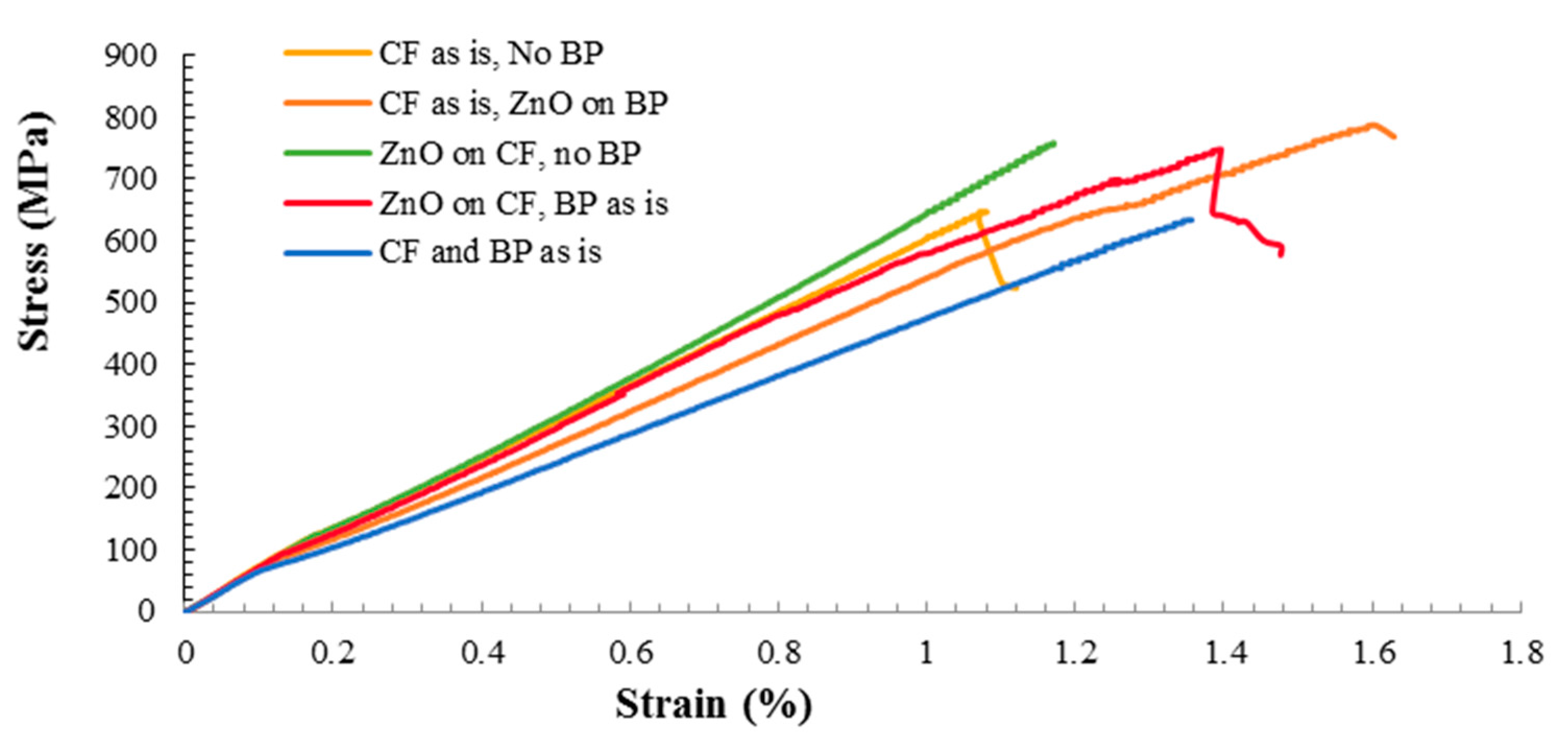
Figure 5.
Comparison of normalized strength for the different composites configurations.
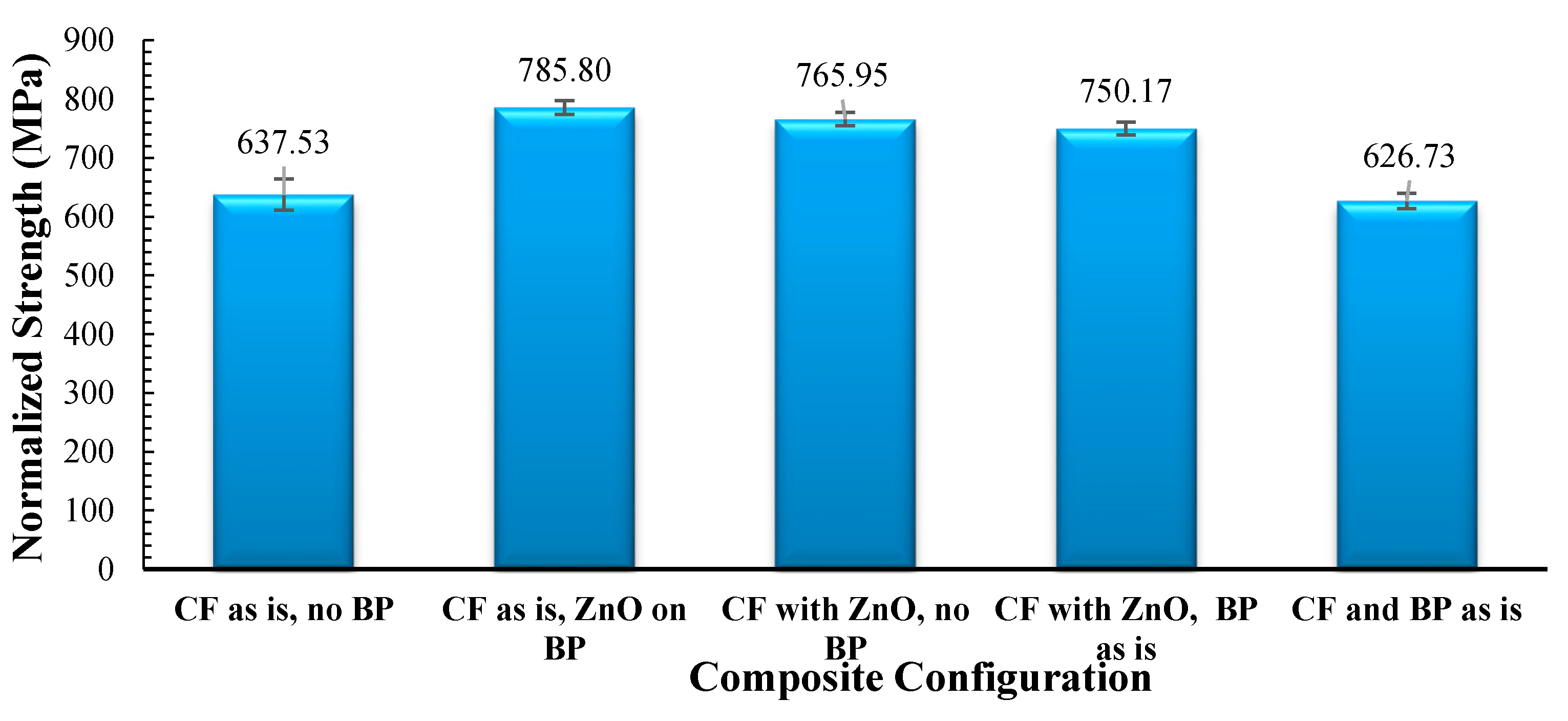
Figure 6.
Comparison of normalized stiffness for different configurations.

Figure 7.
Delamination in composites based on carbon fibers and Bucky paper without ZnO nanorods.

Figure 8.
Micrographs of the fracture surfaces of the composites based on (a) CF and no BP no ZnO; (b) CF and ZnO on BP; (c) ZnO on CF and no BP; (d) ZnO on CF, BP as is and (e) CF and BP as is no ZnO.
Figure 8.
Micrographs of the fracture surfaces of the composites based on (a) CF and no BP no ZnO; (b) CF and ZnO on BP; (c) ZnO on CF and no BP; (d) ZnO on CF, BP as is and (e) CF and BP as is no ZnO.

Figure 9.
The variation of tan delta with temperature for the various composite configurations.
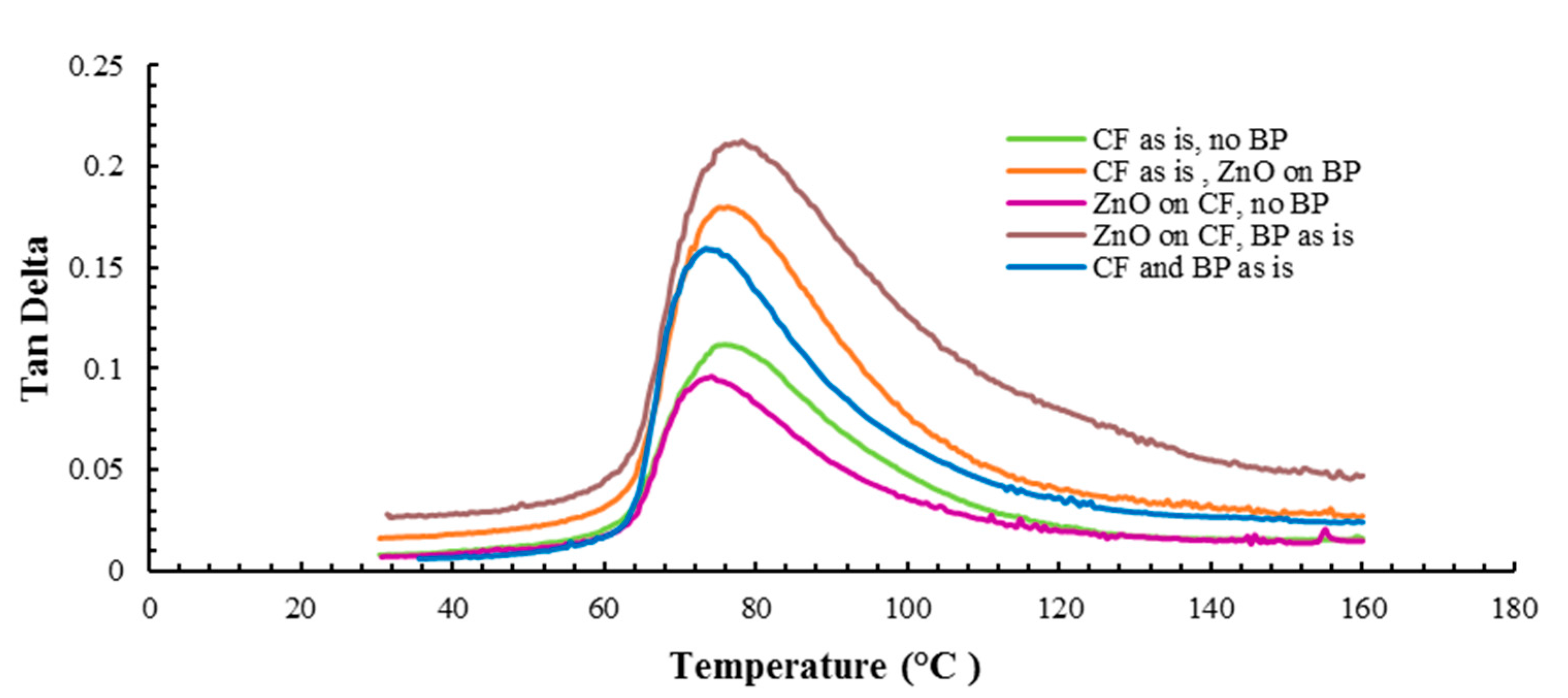
Figure 10.
The variation of storage modulus with temperature for the various composites configurations.
Figure 10.
The variation of storage modulus with temperature for the various composites configurations.

Figure 11.
The variation of tan (δ) with frequency at 30 °C for the various composite configurations.
Figure 11.
The variation of tan (δ) with frequency at 30 °C for the various composite configurations.
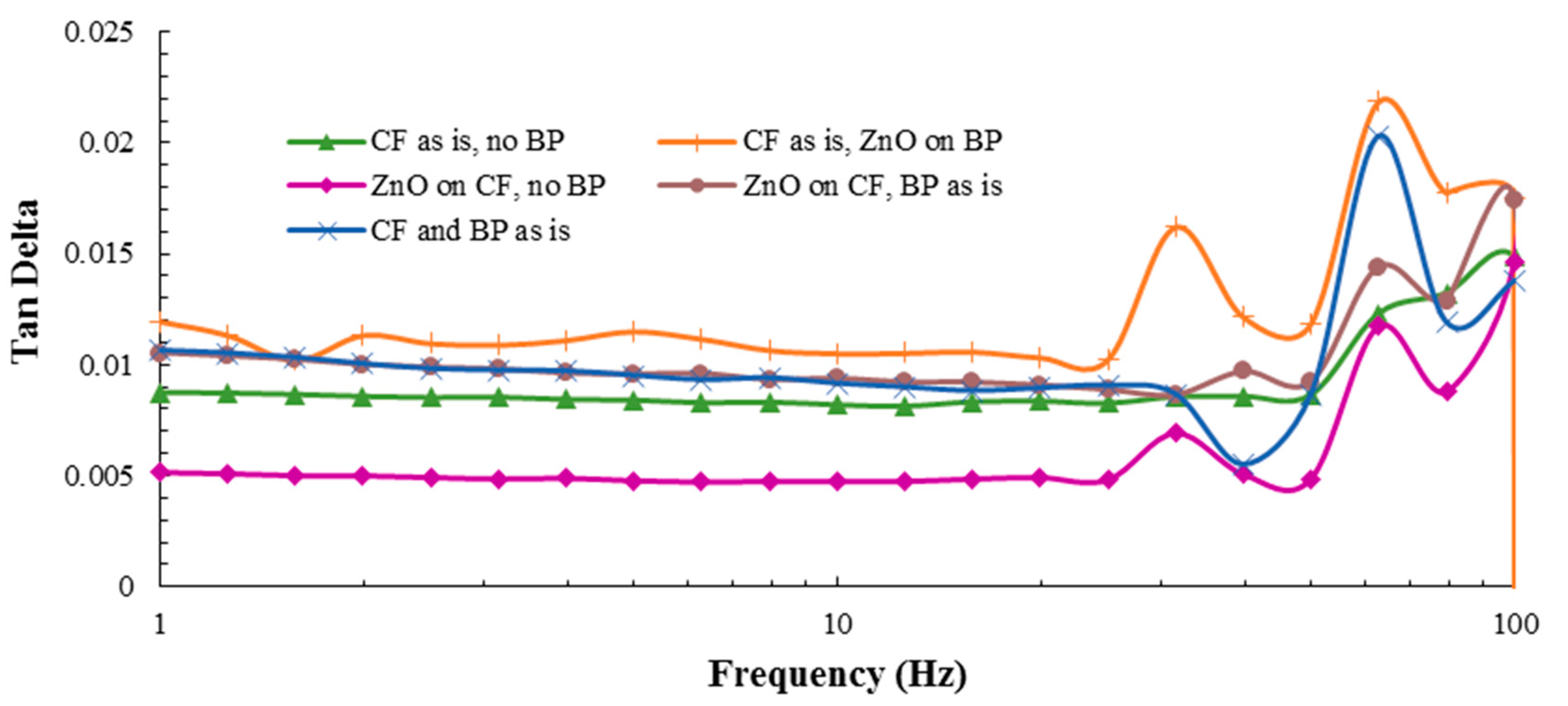
Figure 12.
The variation of storage modulus with frequency at 30 °C for various configurations of two-layer composite samples.
Figure 12.
The variation of storage modulus with frequency at 30 °C for various configurations of two-layer composite samples.

Table 1.
Percentage changes in strength and stiffness with respect to composites based on carbon fiber (CF) only.
Table 1.
Percentage changes in strength and stiffness with respect to composites based on carbon fiber (CF) only.
| Configuration | % Change in Strength | % Change in Stiffness |
|---|---|---|
| CF as is, ZnO on BP | 23.26 | 1.98 |
| ZnO on CF, no BP | 20.14 | 2.61 |
| ZnO on CF, BP as is | 17.67 | 3.36 |
| CF and BP as is | −1.69 | −13.88 |
Table 2.
Percentage change of tan delta (at 75 °C) and storage modules (at 60 °C) in thermal DMA scan at 30 °C and 1.0 Hz with respect to the composite based on CF only.
Table 2.
Percentage change of tan delta (at 75 °C) and storage modules (at 60 °C) in thermal DMA scan at 30 °C and 1.0 Hz with respect to the composite based on CF only.
| Configuration | % Change in Tan (δ) | % Change in Storage Modulus |
|---|---|---|
| CF as is, ZnO on BP | 60.98 | 536.09 |
| ZnO on CF, no BP | −15.86 | 309.79 |
| ZnO on CF, BP as is | 86.6 | 411 |
| CF and BP as is | 41.6 | 441.284 |
Table 3.
Percentage change of tan delta (at 63 Hz) and storage modulus (independent of frequency) during frequency scan at 30 °C with respect to the composite based on CF only.
Table 3.
Percentage change of tan delta (at 63 Hz) and storage modulus (independent of frequency) during frequency scan at 30 °C with respect to the composite based on CF only.
| Configuration | % Change in Tan (δ) | % Change in Storage Modulus |
|---|---|---|
| CF as is, ZnO on BP | 86.20 | 202.86 |
| ZnO on CF, no BP | 0 | 122.86 |
| ZnO on CF, BP as is | 22.73 | 90.86 |
| CF and BP as is | 72.76 | 116 |
Table 4.
The trend of surface resistivity for various configurations of two-layer composite samples.
Table 4.
The trend of surface resistivity for various configurations of two-layer composite samples.
| Configuration | Length (mm) | Width (mm) | Resistance (Ω) | Volume Resistivity (Ωm) |
|---|---|---|---|---|
| CF as is, no BP | 56.21 | 5.71 | 19 | 0.00095 |
| CF as is, ZnO on BP | 56.46 | 6.51 | 3.93 | 0.00023 |
| ZnO on CF, no BP | 66.11 | 5.17 | 7.5 | 0.00028 |
| ZnO on CF, BP as is | 66.71 | 6.62 | 4.67 | 0.00026 |
| CF and BP as is | 66.78 | 5.6 | 4.12 | 0.00019 |
© 2018 by the authors. Licensee MDPI, Basel, Switzerland. This article is an open access article distributed under the terms and conditions of the Creative Commons Attribution (CC BY) license (http://creativecommons.org/licenses/by/4.0/).
Share and Cite
MDPI and ACS Style
Ayyagari, S.; Al-Haik, M.; Rollin, V. Mechanical and Electrical Characterization of Carbon Fiber/Bucky Paper/Zinc Oxide Hybrid Composites. C 2018, 4, 6. https://doi.org/10.3390/c4010006
AMA Style
Ayyagari S, Al-Haik M, Rollin V. Mechanical and Electrical Characterization of Carbon Fiber/Bucky Paper/Zinc Oxide Hybrid Composites. C. 2018; 4(1):6. https://doi.org/10.3390/c4010006
Chicago/Turabian StyleAyyagari, Suma, Marwan Al-Haik, and Virginie Rollin. 2018. "Mechanical and Electrical Characterization of Carbon Fiber/Bucky Paper/Zinc Oxide Hybrid Composites" C 4, no. 1: 6. https://doi.org/10.3390/c4010006
Note that from the first issue of 2016, this journal uses article numbers instead of page numbers. See further details here.