Hybrid Carbon-Based Clathrates for Energy Storage

Materials Engineering Department, Southwest Research Institute, San Antonio, TX 78238, USA
C 2018, 4(1), 7; https://doi.org/10.3390/c4010007
Submission received: 9 November 2017
/
Revised: 3 January 2018
/
Accepted: 18 January 2018
/
Published: 22 January 2018
(This article belongs to the Special Issue Carbon Hybrid Materials)
Abstract
:Hybrid carbon–silicon, carbon–nitrogen, and carbon–boron clathrates are new classes of Type I carbon-based clathrates that have been identified by first-principles computational methods by substituting atoms on the carbon clathrate framework with Si, N, and/or B atoms. The hybrid framework is further stabilized by embedding appropriate guest atoms within the cavities of the cage structure. Series of hybrid carbon–silicon, carbon–boron, carbon–nitrogen, and carbon-silicon-nitrogen clathrates have been shown to exhibit small positive values for the energy of formation, indicating that they may be metastable compounds and amenable to fabrication. In this overview article, the energy of formation, elastic properties, and electronic properties of selected hybrid carbon-based clathrates are summarized. Theoretical calculations that explore the potential applications of hybrid carbon-based clathrates as energy storage materials, electronic materials, or hard materials are presented. The computational results identify compositions of hybrid carbon–silicon and carbon–nitrogen clathrates that may be considered as candidate materials for use as either electrode materials for Li-ion batteries or as hydrogen storage materials. Prior processing routes for fabricating selected hybrid carbon-based clathrates are highlighted and the difficulties encountered are discussed.
1. Introduction
Type I and Type II carbon clathrates (C46 and C136), which can be considered as analogs of carbon fullerene materials, are composed with face-sharing C20, C24, and C28 cages linked through sp3-covalent bonds. Theoretical computations have shown that both Type I carbon clathrate (C46) and Type II carbon clathrate (C136) may exist as metastable phases under high pressures [1,2,3]. The cage structure of Type I carbon clathrate, C46, is shown in Figure 1. Insertion of guest atoms such as Li, Na, or Ba into the cage structures has been predicted to be feasible under high pressures. However, the energies of formation for the Type I and Type II carbon clathrates are extremely high and neither Type I nor Type II carbon clathrates have been synthesized. On the other hand, Type I and Type II silicon clathrates (Si46 and Si136), which are composed with face-sharing Si20, Si24, and Si28 cages, have been synthesized via a number of processing routes. Furthermore, various types of Type I and Type II silicon-based clathrates have also been synthesized with and without framework substitution. Substitution of the framework Si atoms with alloying elements such as Al, Cu, Ni, Ag, and among others Zn, have been reported [4]. The framework-substituted compounds are actually more stable and exhibit improved electronic, thermoelectric, and superconductive properties compared to the stoichiometric counterparts. These experimental observations suggest that it might be possible to develop a new class of hybrid carbon clathrates by substituting the carbon framework in C46 or C136 with Si, nitrogen, or boron atoms.
The aim of this article is to review the current research on hybrid carbon-based clathrates, including the theoretical basis of the compounds and their properties, the synthesis of selected compounds, and their potential applications as energy storage materials. The current status of carbon clathrates is summarized first. The applications of first-principles methods to designing and identifying potential hybrid carbon–silicon clathrates are then highlighted. The potential applications of these hybrid carbon clathrates as energy storage materials, electronic or electrode materials, as well as hard materials, are explored and assessed. Current Li-ion batteries utilize C- or Si-based anodes. The cage structures of hybrid carbon clathrates may enable Li storage and promote the development of high capacity anodes for Li-ion battery applications. Lastly, the current status of the synthesis of selected carbon–silicon and carbon–nitrogen clathrates are reported and their challenges are discussed, followed by a summary and conclusions.
2. Carbon Clathrates
Type I carbon clathrate, C46, is comprised of a framework of C atoms forming a 3D cage structure in sp3 bonding [5]. The unit cell of C46 is depicted with the positions of the Wyckoff sites in Figure 1a, while the cage structure is shown in Figure 1b. Type I carbon clathrate, C46, consists of 46 sp3 C with a regular arrangement of two 20-atom cages and six 24-atom cages that fuse together through five-atom pentagonal rings and occasionally six-atom rings (Figure 1b). The bond angle of the five-atom pentagonal rings is 108°, while it is 109.49° for the six-atom hexagonal rings [5]. The structure is simple cubic (sc) with a lattice parameter of 6.696–6.722 Å and 46 C atoms per unit cell [1,2]. The crystal structure of C46 clathrate belongs to the space group and space group number 223 [1,2]. Type I clathrates can be alloyed by framework substitution and guest atom insertion into the cage structure. For example, some of the framework atoms of a Type I clathrate can be substituted by atom M, while the empty space within the cage structure can serve as host sites for guest atoms A, as shown in Figure 1b. There are two small cages that can host two guest atoms at the Wyckoff 2a sites and there are six large cages that can host six atoms at the Wyckoff 6d sites without a significant effect on the unit cell volume. Type I alloyed carbon clathrates can be described by the formula: AxMyC46-y [1,3,4], where A and M represent the guest and substitution atoms and x and y represent the number of guest and substitution atoms, respectively. A representative C framework and the Li guest atoms at Wyckoff 2a and 6d sites are shown in Figure 1b. The structure of Type II carbon clathrate (C136) is comprised of four C20 cages and two C28 cages that are fused together through six-atom hexagonal rings. It has a face-centered cubic structure (fcc) and belongs to the space group Fd3m with 34 atoms per unit cell or 136 atoms per supercell. The lattice parameter of C136 is about 9.647–9.689 Å, as tabulated in Table 1 [2]. The hexagonal carbon clathrate (hcp-C40) is comprised of three C20, two C24, and two C26 cages; it belongs to the space group P6/mmm with 40 atoms per unit cell. The lattice parameters of Type I, Type II, hexagonal carbon, graphite, and diamond are compared in Table 1 [2].
Hypothetical carbon clathrates were first investigated by Nesper et al. [5] who used density functional theory (DFT) to examine the cage-like structures that can be derived from zeolites or are related to the zeolite topology. Most of the compounds investigated by Nesper et al. exhibit higher formation energy compared to that of carbon with diamond structure, but carbon clathrate I and II exhibit only slightly higher formation energies than diamond. Benedek et al. [6] identified fcc-C34, hcp-C40, and sc-C46 as the first three periodic lattices in a series of polyhedric sp3 carbon networks that are formed under the topological restrictions of four-fold coordination comprised of only five- or six-fold rings. A theoretical study of the phase stability of carbon clathrates at high pressures revealed that fcc-C138 (Type II) and sc-C46 (Type I) are, respectively, the third and fourth most stable carbon phase after diamond and graphite [2]. A pressure-induced phase transition from graphite to fcc-C138 is predicted to occur at a pressure of around 17 GPa and about 21 GPa for C46. Additional carbon compounds at higher energy states include those of hcp-C40 and M-carbon [2]. Ker et al. [15] suggested that small atoms such as Li and Be may be intercalated into the cages of Type I carbon clathrates to enhance phase stability. First-principles computations by Bernasconi et al. [16] showed that hcp-C40 is suitable to be n doped by Li insertion and p doped by substitutional B. Theoretical computations by Rey et al. [1] showed that Li atoms can indeed be intercalated into the small cages of C46 to form Li8C46 but the energy of formation of the lithiated compound is increased compared to the unlithiated C46 [1]. These investigators also showed that the minimum energy barriers for attaining C46 and Li8C46 may be reached at a pressure close to 40 GPa, suggesting that these metastable phases may be synthesized under extreme conditions of high pressure and temperature [1]. Reported synthesis of 3D cage-like covalent crystals such as C20 [17], C36 [18], and traces of other compounds such as C60 and C70 [7,18] suggests that the high-temperature and high-pressure route might be a viable processing method. Unfortunately, no carbon clathrates have been synthesized so far. The bonding type (i.e., sp3 or sp2) of some of these carbon clusters has not been characterized or positively identified.
3. Hybrid Carbon–Silicon Clathrates
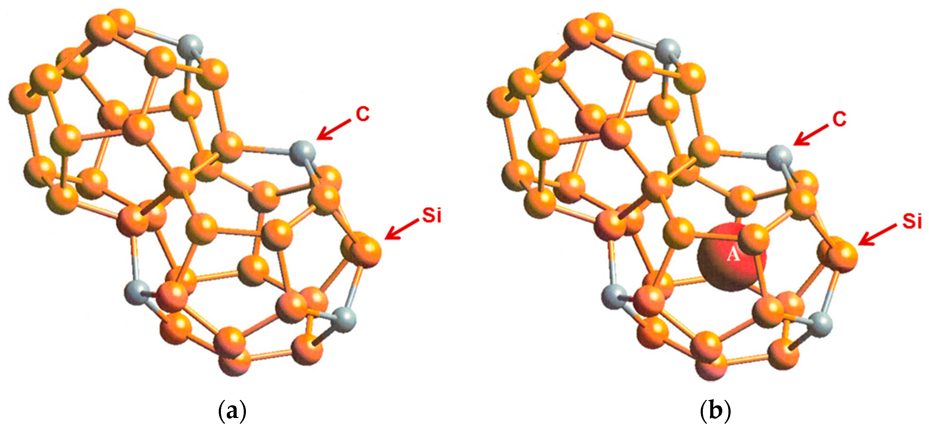
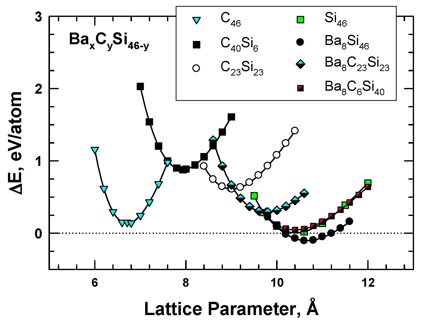
To overcome the difficulties associated with synthesizing carbon clathrates under extreme conditions, Chan et al. [8] considered the use of first-principles methods to identify appropriate small-sized atoms that could be amenable to the formation of new silicon-based clathrate compounds for energy storage and/or harvesting applications. This approach was motivated by the recognition that silicon clathrates are readily synthesized by conventional processing methods. As such, a clathrate with a hybrid carbon–silicon framework may be more amenable to conventional processing than that with a carbon framework. Thus, a series of Type I hybrid carbon–silicon compounds was designed by substituting some of the Si atoms on the Si46 framework with C atoms in order to identify the potential hybrid carbon–silicon clathrate compounds that exhibit favorable energy of formation for synthesis by conventional methods. First-principles computations were performed by Chan et al. [8] based on the Car–Parrinello molecular dynamics (CPMD) code [13,14] to investigate the effects of carbon substitution on a Si46 framework. These calculations indicate that carbon atoms can partially substitute Si atoms on the Si46 framework to form a metastable hybrid silicon–carbon clathrate, which can be represented by the chemical formula CySi46-y. Figure 2a shows a representation of the Type I CySi46-y clathrates. Furthermore, guest atoms can be inserted into the cage structure to stabilize the hybrid silicon–carbon clathrate by reducing the energy of formation, forming a class of new hybrid silicon and carbon clathrates represented as AxCySi46-y. These hybrid structures do not exist in nature and, thus, represent a novel structure of matter. Figure 2b shows a structural representation of the Type I AxCySi46-y clathrate compounds. The computed values for changes in the energy of formation per atom for selected Ba8CySi46-y, C46, C40Si6, and C23Si23 are compared with those for Si46 and Ba8Si46 in Figure 3. The minima of the energy change curves of these Ba8CySi46-y clathrate compounds are positive, indicating that these compounds are metastable.
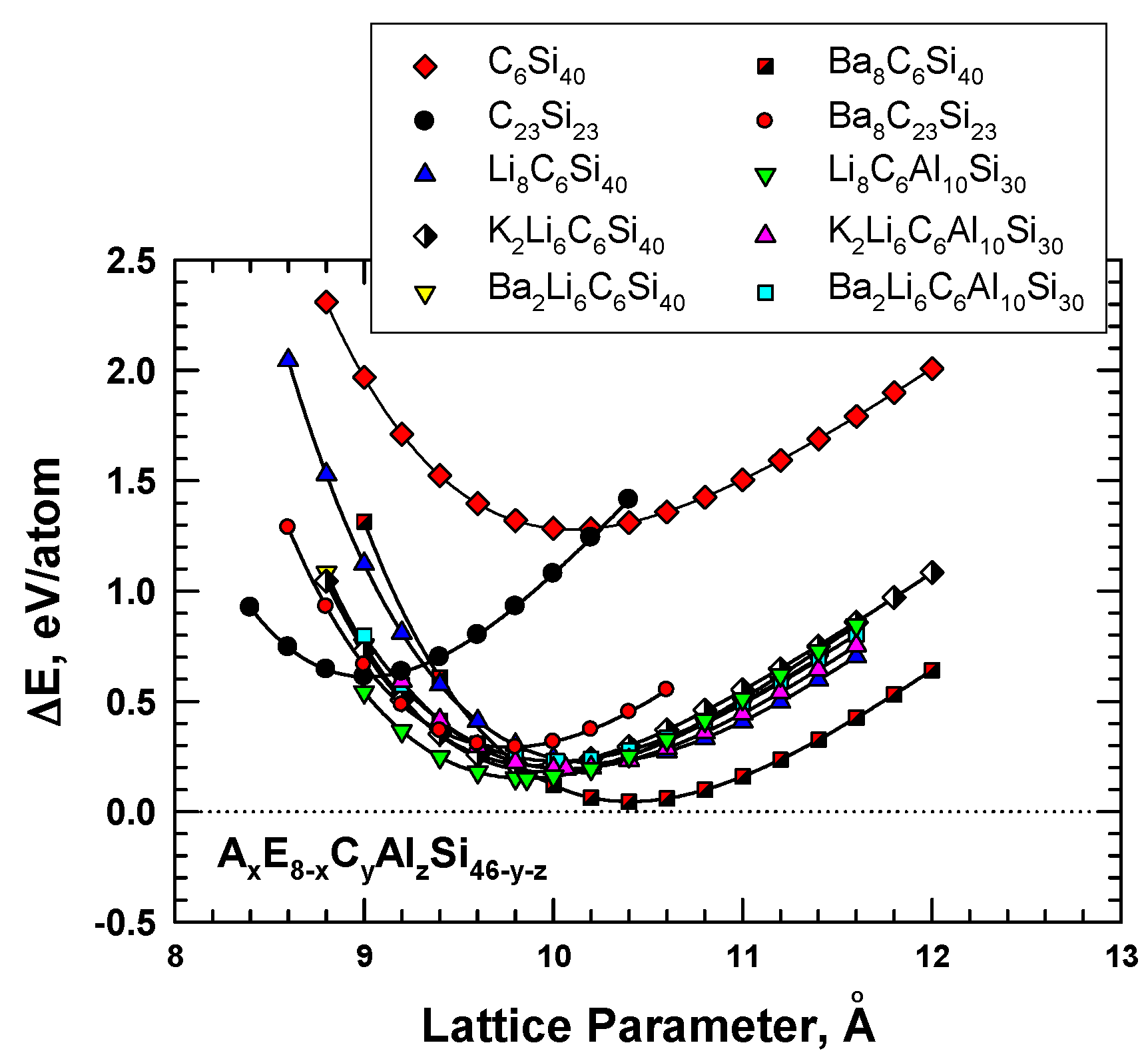
The role of the guest atoms on the energy of formation (ΔEf) of hybrid carbon–silicon clathrates was examined by inserting Li, K, Na, and Ba into the cage structure as guest atoms. Figure 4 presents the energy calculations for these hybrid carbon–silicon clathrates. The results show that several hybrid carbon–silicon clathrates exhibit relatively low ΔEf values. Specifically, the energy of formation values for certain AxC6Si40 are about 0.3 eV or less. Furthermore, the lattice parameter of these Type I clathrates can be lowered by inserting appropriate guest atoms into the cage structure.
AxE8-xCyAlzSi46-y-z are variant compounds of the AxCySi46-y clathrates that are formed by multiple alloying schemes, including (1) inserting guest atoms (A and E) into the cage structure, and (2) substituting C and Al atoms in the framework. The substitution of Al in the framework was motivated by the successful processing of these compounds by conventional vacuum arc-melting techniques [19]. According to the first-principles computations reported by Chan et al [8], Al substitution causes the framework to expand and leads to a larger lattice parameter, while C substitution produces the opposite effect, as shown in Figure 4. The insertion of guest atoms such as Ba, K, and Li tends to improve the stability of Al- and C-substituted frameworks by reducing the energy of formation. In addition, the equilibrium lattice constant and the framework size can be decreased by inserting alkaline atoms, as shown in Figure 4, for Li8C6Al10Si30 and Ba2Li6C6Al10Si30.
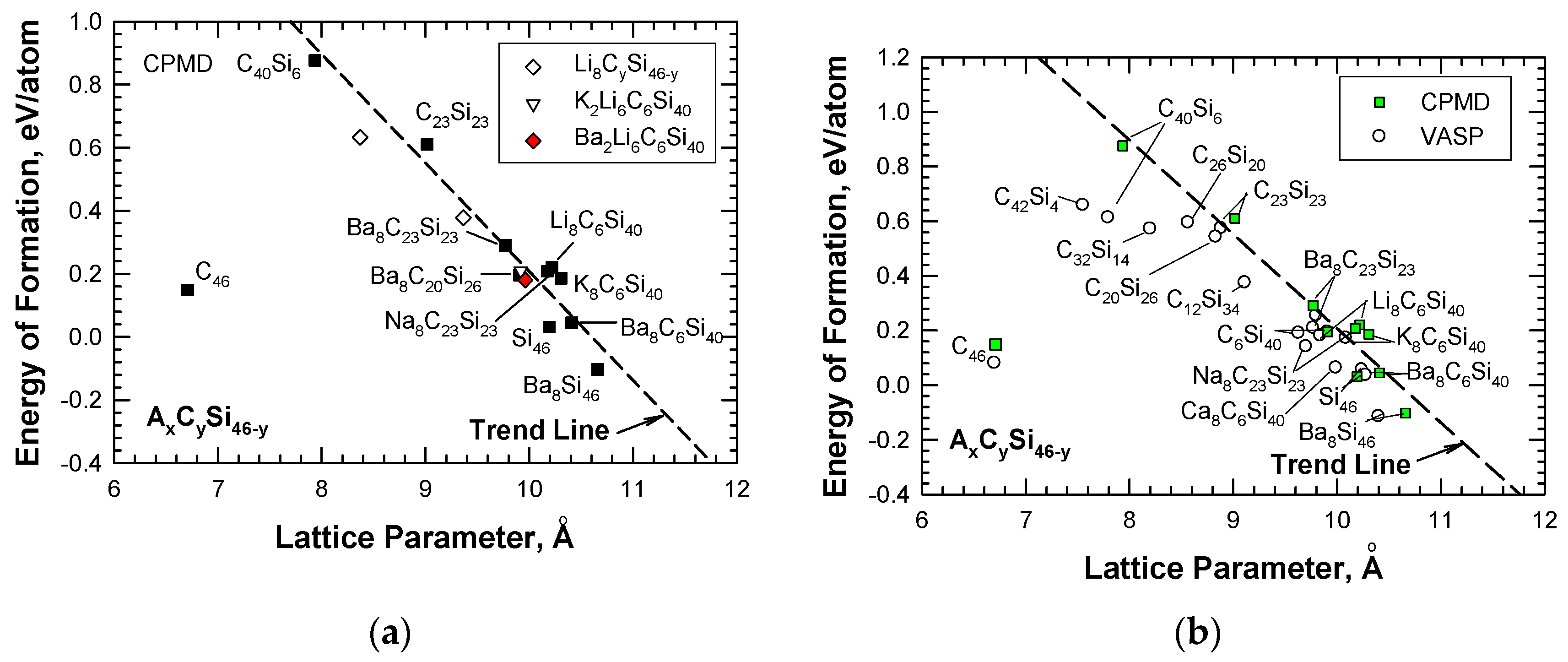
The CPMD results were used to establish a correlation between the energy of formation and the lattice parameter for hybrid carbon–silicon clathrates AxCySi46-y with guest atoms A, which include alkaline metals such as Li, Na, K, and Ba. The correlation (shown in Figure 5a) indicates that the alkaline guest atoms generally lower the energy formation but increase the lattice constant of the hydride clathrates. Figure 5a depicts that all of the carbon-substituted silicon clathrates exhibit positive values of energy of formation, indicating that these clathrate compounds are metastable. Figure 5a also shows that the trend line deviates from C46. To validate the CPMD computations, the energies of formation for the same series of hydride clathrates were computed using the Vienna Ab initio Simulation Package (VASP) code [12]. These two sets of energy of formation computations for AxCySi46-y are compared in Figure 5b, which shows that, in general, there is good agreement between the CPMD and VASP computations, including the energy of formation for C46. One source of the discrepancies between VASP and CPMD computations for C40Si6 has been identified to arise from the slight differences in the relaxed atom positions. As the number of carbon atoms in the framework increases, the VASP results for the carbon-rich clathrates tend to deviate from the trend and lean toward C46. Nonetheless, a gap remains between C46 and carbon-rich clathrates such as C42Si4 and C40Si6. The finding suggests that the energy and lattice parameters of C46-xSix increase rapidly when x is in the range of 1 < x < 4. In addition, the computed value of the energy of formation is sensitive to the relaxed atom positions.
4. Hybrid Carbon–Nitrogen and Carbon–Boron Clathrates
4.1 Hybrid Carbon–Nitrogen Clathrates
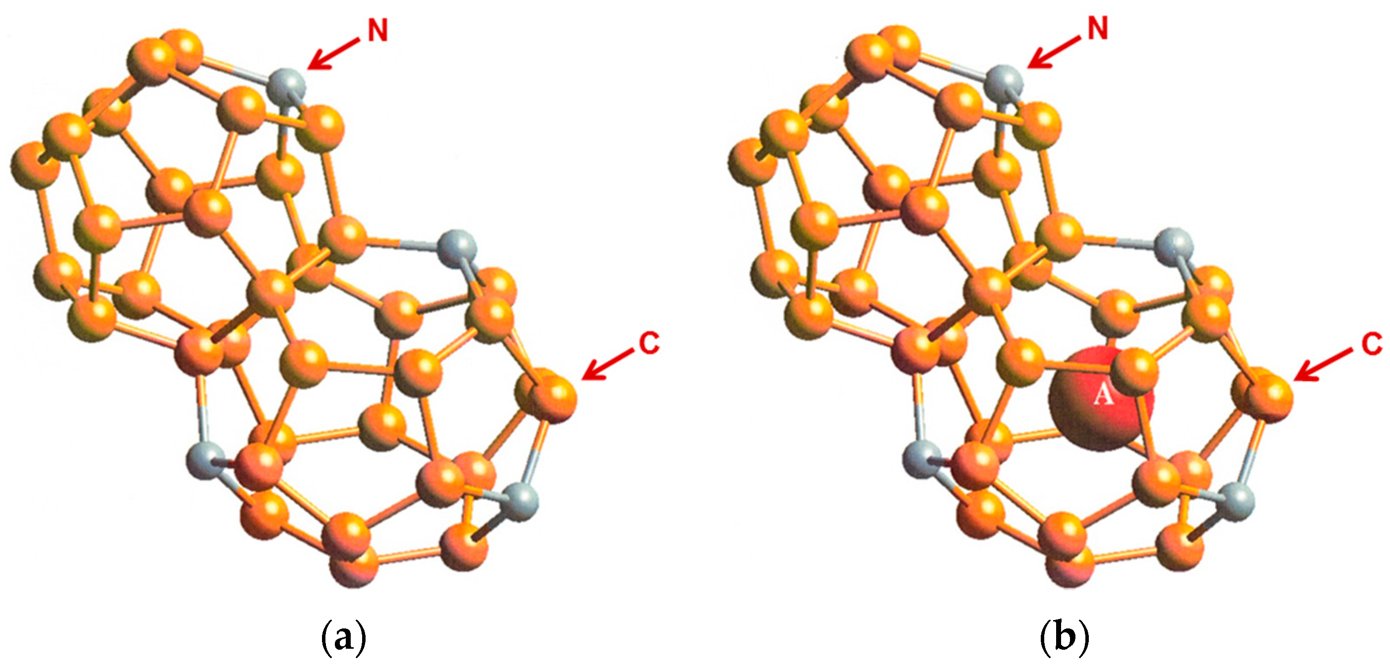
First-principles computational studies by Chan et al. [20] using the Car-Parrinello molecular dynamics (CPMD) code [13,14] indicate that hybrid carbon–nitrogen clathrates, NyC46-y, may be formed by substituting selected carbon atoms with nitrogen atoms in the C46 framework. The structure of Type I NyC46-y clathrates is presented in Figure 6a. Insertion of a guest atom A (e.g., Li) into the cage structure leads to the formation of AxNyC46-y. Figure 6b shows a structural depiction of Type I AxNyC46-y clathrate with a Li guest atom.
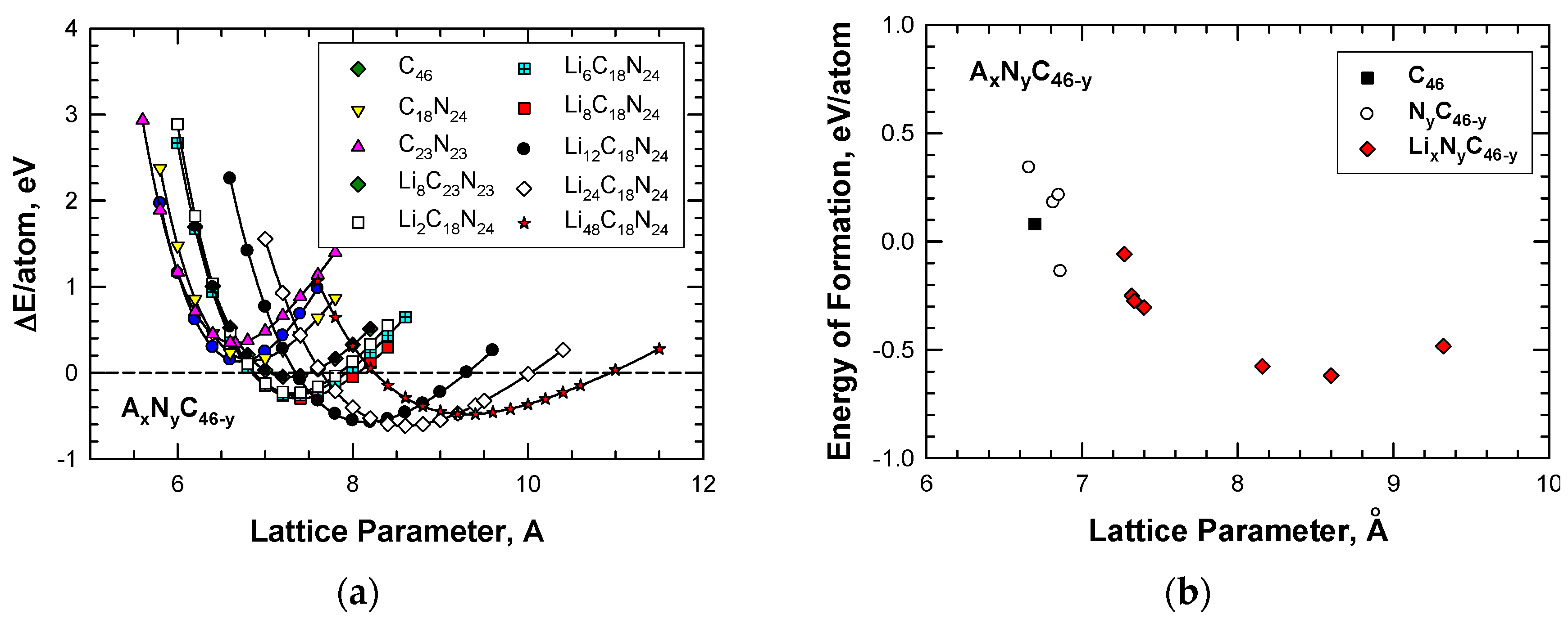
According to the first-principles computations by Chan et al [20], Li insertion improves the stability of the hybrid C–N framework. Figure 7a shows that insertion of Li atoms lowers the energy formation and at the same time expands the framework to a large lattice parameter when the number of Li atoms inserted into the cage structure is increased from 2 to as high as 48. For illustration, Table 2 presents a summary of the energies of formation, together with the corresponding lattice constants, for Type I carbon-based clathrate compounds with and without Li insertion. In addition, the computed values of the energy of formation per atom for these carbon-based clathrate compounds, which include C46, NyC46-y-z, and LixNyC46-y, are presented in Figure 7b. From the results presented in Figure 7b, it is apparent that at the proper nitrogen level, nitrogen substitution can reduce the energy of formation and improve the stability of the NyC46-y framework compared to carbon clathrate (C46). Furthermore, Li insertion reduces the energy of formation of the LixNyC46-y clathrates to negative values, which indicates that these compounds are more stable than C46.
4.2. Hybrid Carbon–Boron Clathrates
Using VASP [12], Zeng et al. [21] computed the energy of formation and band gaps for five different Li-filled, B-substituted carbon clathrates including Li8C38B8 (Type I), Li6C28B6 (Type II), Li7C33B7 (Type IV), Li2C10B2 (Type VII), and Li6C28B6 (Type H) at the ground state. A range of strategies has been utilized to determine the energetics of replacing selected carbon atoms on the framework with boron substitution atoms and Li insertion in order to achieve a lower enthalpy and a more stable clathrate compound. These strategies have included crystal symmetry, charge distribution, strengthening bonding, relieving bond angle, and reducing lattice strain. Based on these strategies, a representative low-enthalpy Li-doped, B-substituted candidate for each type of the five clathrates has been identified. Several energetically competitive structures, however, exist for each clathrate type. These authors concluded that B substitution stabilizes the cage structure and substantially lowers the energy cost for inserting Li atoms into the clathrate cages to about −2eV/Li at 1 atm pressure [21]. In addition, all five carbon clathrates display a semiconducting electronic structure. Li doping of the B-substituted carbon clathrates reduced the band gaps of the carbon clathrate compounds to the range of 0.6 to 2.9 eV [21].
Zeng et al. [21] also investigated theoretically two possible competing routes for synthesizing LixCyBx: (1) formation of LiBC and (2) the introduction of C vacancies. The authors indicated that LiBC formation is thermodynamically feasible but the process may be kinetically limited due to structural differences between LiBC and LixCyBx. The C-vacancy route, on the other hand, may be a costly process for stabilizing Li insertion in comparison to B substitution of the carbon framework. Because of kinetic constraints, the authors suggested that some of the LixCyBx clathrates may exist in amorphous forms.
5. Potential Applications of Hybrid Carbon Clathrates
5.1. Hybrid Carbon–Silicon Clathrates as Hydrogen Storage Materials
In an investigation focused on identifying new Si-based clathrates that may be suitable for use as hydrogen storage materials in transportation applications, Chan et al. [22] applied the VASP code [12] to compute the binding energy of hydrogen molecules in selected Type I Si-based and hybrid carbon–silicon clathrates. Si-based intermetallic clathrates were designed in two ways: (1) with or without an alkali metal guest atom (Na, Li, or Ba) in the cage structure, and (2) substitution of the Si framework with the insertion of other atoms such as C, Al, and Cu, in order to tune the void space inside the cage structure for maximum H2 capacity and optimum binding interactions.
The DFT results of the binding energy (in eV/H2) for hydrogenation of Si46, C6Si40, Na8Al8Si38, and Li8Al8Si38 are presented in Figure 8a, which plots the binding energy versus gravimetric capacity in weight percentage. The gravimetric capacity was computed on the basis of the number of H2 molecules stored within the cage structure. The dashed lines in Figure 8a indicate the desirable binding energy range for H2 storage at ambient temperature. The results presented in Figure 8a show that the H2 binding energy for Si46 and C6Si40 increases with the number of H2 molecules stored within the cage structure. In addition, Figure 8a shows that Na8Al8Si38 and Li8Al8Si38 exhibit hydrogen binding interactions that are within the desirable range for the entire range of gravimetric capacity considered, ranging from 8 to 128 H2 molecules inserted. This finding suggests that Na8Al8Si38 and Li8Al8Si38 may possess a high capacity for physisorption of H2 with suitable binding energy values for the potential application as H2 storage materials at ambient temperature.
Figure 8b presents the lattice parameters of Si46, C6Si40, Na8Al8Si38, and Li8Al8Si38 at several hydrogenation levels. From Figure 8b, it can be seen that the lattice parameters of hydrogenated Na8Al8Si38 and Li8Al8Si38 increase with increasing gravimetric capacity, while those of hydrogenated Si46 and C6Si40 do not exhibit similar increases with gravimetric capacity. For comparison purposes, Figure 8b also presents the U.S. Department of Energy’s (DOE’s) system-level storage targets for onboard storage for vehicles for 2020 and for the fleet [23]. Both gravimetric and volumetric targets are presented in Figure 8b.
Figure 9 presents the results of the lattice parameters for hydrogenated Si46, C6Si40, Na8Al8Si30, and Li8Al8Si38 as a function of volumetric capacity. From Figure 9, it appears that both the hybrid carbon and silicon clathrates (i.e., Si46, C6Si40, Na8Al8Si30, and Li8Al8Si38) might be considered as promising storage materials since their volumetric capacities are in excess of the DOE targets for future vehicles beyond 2020. Moreover, alloyed clathrates that are stabilized by Ba, Na, or Li guest atoms tend to expand more than hydrogenated Si46 and C6Si40 at the same level of volumetric capacity. This finding suggests that hybrid carbon clathrate with a large unit cell (i.e., a large lattice parameter) may be an important and desirable attribute for achieving a high volumetric capacity for hydrogen storage. A number of hybrid Type I carbon–silicon clathrates with large lattice constants have been identified (see Figure 5). Unfortunately, the hydrogen storage capabilities of these hybrid clathrates have not been evaluated or assessed. By virtue of the large lattice constants, Type II carbon-based clathrates might also have suitability for hydrogen storage; however, their hydrogen storage capacities have, so far, not been investigated.
5.2. Hybrid Carbon–Silicon Clathrates as Electronic or Electrode Materials
Chan and Peng [24] employed the first-principles DFT code VASP [12] to compute the energy of formation and the optimal lattice constants of several hybrid carbon–silicon clathrates. In addition, they also computed the electronic structures including the band structure, density of states (DOS), and the spd- and site-projected partial density of states (PDOS) of the selected materials. Geometry optimization and self-consistent total energy calculations were performed using the PBE functional [25] and projector-augmented wave (PAW) [26,27] potentials along with the plane wave basis sets. Besides the PBE functional [25], the Hyed–Scuseria–Ernzerhof (HSE) screened Coulomb hybrid density functional [28] was also utilized to predict the energy band gap for Si46 in order to gain a perspective on potential underestimations in the PBE band gap results. Detailed descriptions of the computational methods and results can be found in Chan and Peng [24].
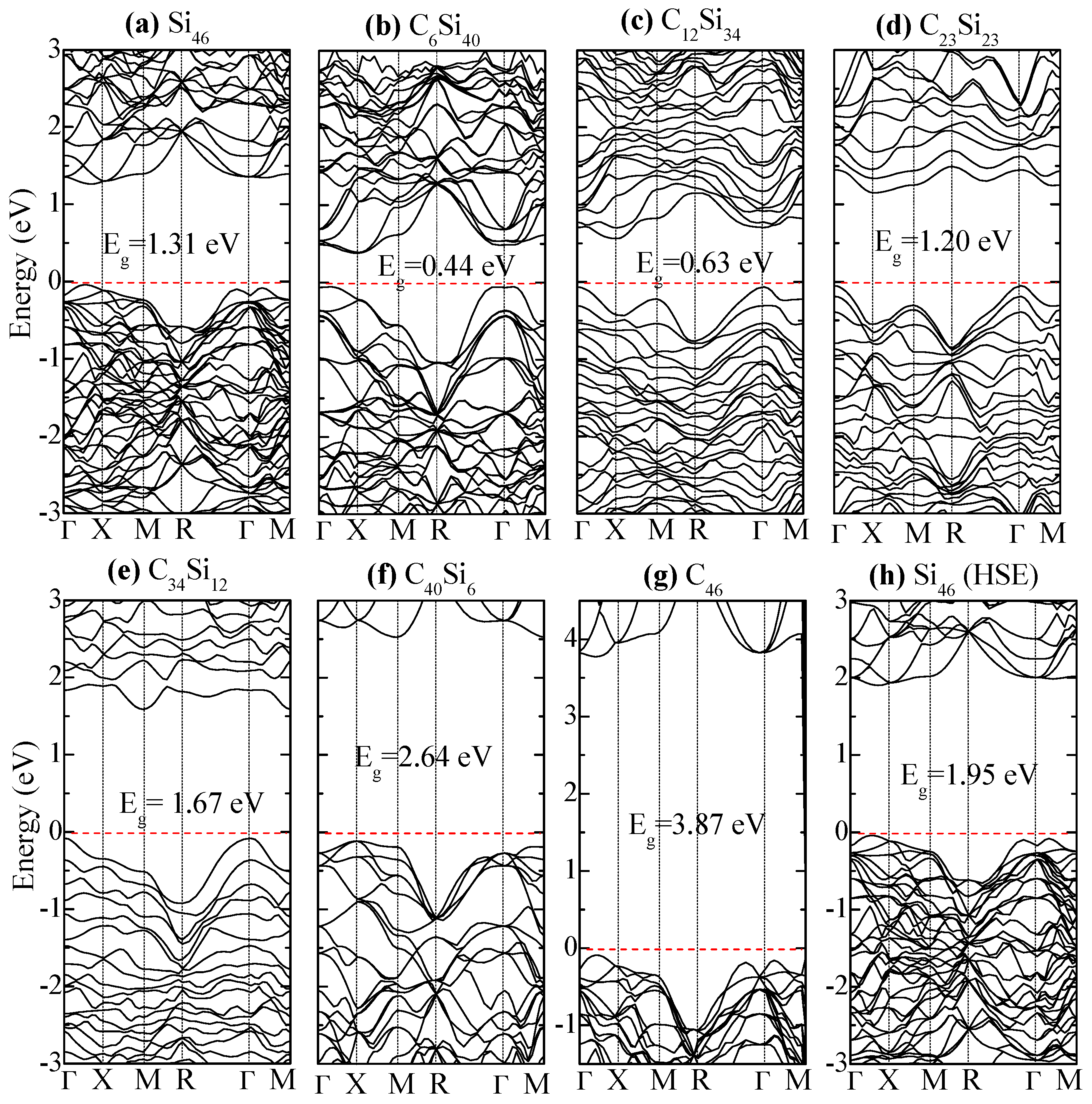
Figure 10 compares the electronic band structure of Si46, C6Si40, C12Si34, and C23Si23. The Fermi level is set at zero eV (i.e. the top edge of valence band). For Si46, a relatively large band gap is (Eg = 1.31 eV) observed between the Fermi level and the lower edge of the conduction band. The band gap is reduced to Eg = 0.44 eV in C6Si40 when six Si atoms on the framework are replaced by C atoms. Compared to Si46, the band gap is reduced to Eg = 0.63 eV when the substituted C atoms are increased to 12 in C12Si34. Further substitution of Si by C in the framework causes the energy band gap to increase to 1.2 eV, 1.67 eV, and 2.64 eV in C23Si23, C34Si12, and C40Si6, respectively. For C46, the band gap is 3.87 eV, which represents an increase of 2.56 eV compared to Si46. Thus, the hybrid carbon–silicon framework exhibits the lowest band gap when the number of substituted carbon atoms on the framework ranges from 6 to 12.
The total and partial DOS of Si46, C6Si40, C23Si23, and C40Si6 are compared in Figure 11 with the Fermi level, which is shown as the red dashed line at zero eV. Figure 11a shows that the p-electrons of Si contribute to the edges of the valence and conduction bands to form the band gap in Si46. In Figure 11b, a significant contribution by the s-electrons of substituted C atoms to the bottom of the conduction band lowers the band gap of C6Si40. As the number of substituted C atoms per formula unit increases to 23, the conduction bands of C23Si23 are dominated by both the C-p electrons and Si-p electrons; as a result, the band gap is widened again, as shown in Figure 11c. A further widening of the band gap in C40Si6 is presented in Figure 11d.
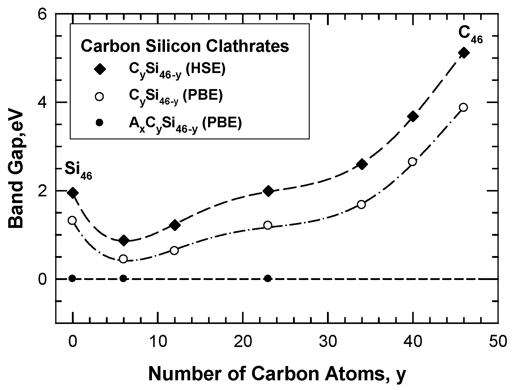
The band gap of the hybrid carbon–silicon clathrates is influenced by the number of substitution C atoms on the framework, as illustrated in Figure 12. Substitution of Si atoms on the Si46 framework by C atoms progressively reduces the band gap due to the interaction of C valence electrons with the Si conduction band. The band gap is reduced with increasing numbers of C atoms on the hybrid Si-C framework when the number of carbon atoms is about 6 to 12. The band gap is widened again when the number of C is increased above 23. Conversely, a large band gap exists for C46 and the band gap is reduced when the C atoms on the C46 framework are substituted by Si atoms. Again, the band gap is reduced with increasing numbers of Si atoms on the hybrid Si-C framework until the number of Si atoms on the framework exceeds 40. A minimum band gap occurs when there are about 6 to 12 carbon atom occupants per formula unit on the framework and the minimum band gap appears to be about 0.44 eV. The general trend of the results indicates that the band gap of the carbon–silicon clathrate framework can be tuned by adjusting the number of carbon atoms on the framework. Furthermore, a metal conductor can be obtained by doping Li, Na, K, Mg, Ca, or Ba atoms inside the cage structure of the framework. The wide band gap and tunability make carbon clathrates potential materials for electronic applications.
The hybrid carbon–silicon clathrates may also be considered as potential electrode materials for Li-ion batteries. The electronic structure calculations indicate that the empty CySi46-y clathrate exhibits a small band gap (0.44 to 0.63 eV) when y, the number of substituted carbon atoms, is in the range of 6 to 12. With this composition range, a small band gap may be induced to provide sufficient electronic conductivity for insertion of lithium ions into the cage structure to proceed when CySi46-y clathrate is used as an anode. Once Li ions are inserted, the electronic conductivity of LixCySi46-y is likely to increase with an increasing number of Li ions inserted; subsequently, the lithiated CySi46-y clathrate may become a metal-like conductor when 8 or more Li ions are inserted [24]. Recent work by Li et al. [29] and Chan et al. [30,31] have shown that lithiation of BaxAlySi46-y and empty Si46 clathrates are feasible even in the presence of Ba atoms occupying some of the sites within the cage structure of BaxAlySi46-y. Thus, it is possible that some of the CySi46-y clathrates doped with the alkaline metals (Na, K) or alkaline earth metals (Ba, Ca, Mg) may be lithiated and serve as potential electrode materials for Li-ion batteries. There are more empty spaces within the cage structure of CySi46-y compared to those in graphite or carbon-based nanomaterials [32]. On this basis, CySi46-y anodes may accommodate more Li storage capacity than conventional graphite anodes or carbon-based nanomaterials [32]. In conventional Si anodes, Li storage is accompanied by the formation of various LiSx silicides. The reaction of Li with CySi46-y anodes to form various forms of LiCx or LiSix compounds [32,33] may provide additional Li storage mechanisms but it would likely destroy the clathrate structure and limit the overall capacity or mechanical performance.
5.3. Hybrid Carbon–Nitrogen Clathrates as Hard Materials
To explore the potential of NyC46-y as hard materials, the bulk modulus of the various intermetallic clathrate compounds was computed by Chan et al. [20] using the first-principles approach according to the expression given by [34]:
in which ΔE/V—the energy change normalized by the unit cell volume—is related to the bulk modulus (B) and the principal strains (δ) applied to the unit cell. To obtain the bulk modulus, ΔE/V values were computed and plotted as a function of the principal strain δ. The ΔE/V data were fitted to Equation (1) and the bulk modulus B was obtained from the regression coefficient. The computed bulk moduli for individual carbon-based clathrate compounds are presented in Table 3. For comparison, Table 3 also presents the experimental values of the bulk modulus for C (diamond), carbon nitrides (α-C3N4 and β-C3N4), cubic silicon nitride (c-Si3N4), and silicon carbide (SiC) obtained from the literature [1,2,3,35,36,37,38,39]. From Table 3, it can be seen that the bulk modulus of Type I hybrid C–N, N–Si, and C–Si clathrates can range from 63 GPa to as high as 400 GPa. For example, the bulk modulus of carbon clathrates such as C18N24, C23N23, and C46 are in the range of 245 GPa to 374 GPa. Though not as high as those of diamond C or β-C3N4, the modulus values of the carbon-based clathrates are comparable to silicon nitride (c-Si3N4) and carbon nitride (SiC). By virtue of a relatively high bulk modulus, carbon clathrates may potentially be used in applications that require hard materials.
6. Synthesis of Hybrid Carbon Clathrates
6.1. Hybrid Carbon–Silicon Clathrates
The synthesis of six candidate carbon–silicon clathrate compounds was attempted by Chan et al. [8]. Table 4 summarizes the target compounds and the materials produced that were selected for synthesis by a vacuum arc-melting method. In particular, all six compositions were packaged and shipped to Sophisticated Alloys, Inc. (Butler, PA, USA) where vacuum arc-melting (VAM) of the candidate alloys was performed. A vacuum arc-melter is comprised of an electrode and a crucible containing the materials to be melted in a metal vessel that is brought to a vacuum of <0.1 Pa. The equipment used for the VAM process is available on the website of Sophisticated Alloys [40]. To fabricate the clathrate compounds, the arc-melting process was conducted in an argon atmosphere under a sub-atmospheric pressure. As indicated in Table 4, only some of the predicted Type I clathrates (which include Ba8C6Si40, Ba8C20Si26, and Ba8C23Si23) have been confirmed by successful synthesis. However, the arc-melted products have been found to be impure and co-mingled with the starting materials [8]. Thus, further efforts are needed to improve both the yield and the purity of the arc-melted products. Despite the low yields (16% to 39%), the successful synthesis of Ba8C6Si40, Ba8C20Si26, and Ba8C23Si23 represents a significant accomplishment since these compounds were synthesized for the first time. The success in synthesizing Ba8C6Si40, Ba8C20Si26, and Ba8C23Si23 by arc-melting may be attributed to the use of SiC in the starting admixture [8].
6.2. Hybrid Carbon–Nitrogen Clathrates
Vacuum arc-melting was employed to synthesize Mg8C18N24 and Ba8C18N24. The starting material was an admixture of graphitic carbon nitride (g-C3N4+yHy) and appropriate metal powders [20]. Arc-melting of Mg8C18N24 was unsuccessful, while arc-melting synthesis of Ba8C18N24 was partially successful. Powder X-ray diffraction (PXRD) measurements of the arc-melted Mg8C18N24 powders has established that all of the peaks in the PXRD pattern can be attributed to those of the graphitic carbon nitride, MgO, and MgCN2, as shown in Table 5, and no peaks can be attributed to Type I carbon clathrates [20]. In contrast, small amounts of Ba8C18N24 were successfully synthesized by arc-melting appropriate amounts of Ba mixed with graphitic carbon nitride (g-C3N4+xHy) [20]. PXRD measurements indicated a mixture of Ba8C18N24, Ba, and g-C3N4 in the arc-melted product. However, the yield and purity are low and further improvements are needed to increase the yield and purity.
7. Summary
This overview summarizes the current status of hybrid carbon–silicon, carbon–nitrogen, and carbon–boron clathrates, which are new classes of Type I carbon-based clathrates that have been identified by first-principles computational methods. These theoretical materials have been designed by substituting atoms on the carbon clathrate framework with Si, N, and/or B atoms. Stability of the hybrid framework may be stabilized by inserting alkaline metal guest atoms within the cavities of the cage structure. A series of hybrid carbon–silicon, carbon–nitrogen, carbon–boron, and carbon–silicon–nitrogen clathrates has been shown to exhibit small positive values for the energy of formation, indicating that they are metastable compounds and may be amenable to fabrication. Theoretical calculations that explore the potential applications of hybrid carbon-based clathrates such as energy storage materials, electronic or electrode materials, as well as hard materials, are presented. The computational results identify compositions of hybrid carbon–silicon, carbon–nitrogen, and carbon–boron clathrates that may be considered as candidate materials for use as electronic materials, hard materials, and electrode materials for Li-ion batteries or as hydrogen storage materials. Fabricating selected hybrid carbon–silicon and carbon–nitrogen clathrates by industrial arc-melting techniques have not always been successful. The major limitations of the current processing techniques are the purity and yield of the products when the candidate materials are successfully synthesized.
One of the current challenges of hybrid carbon clathrates is the development of robust processing methods for synthesizing carbon–silicon, carbon–nitrogen, and carbon–boron clathrates. So far, only an industrial arc-melting method has been attempted to fabricate small quantities of low-purity Ba-containing hybrid carbon–silicon and carbon–nitrogen clathrates. Future development should expand the processing routes beyond arc-melting. Solution processing methods based on Hofmann-type elimination-oxidation schemes such as those described by Chan et al. [30] and Guloy et al. [41] may be desirable since they can be scaled up to produce larger quantities of clathrate materials. However, it is uncertain whether hybrid carbon–silicon, carbon–nitrogen, or carbon–boron clathrates can be produced by solution synthesis methods. Once they are synthesized, the impure hybrid clathrates need to be purified. Development of robust purification routes is another challenge that needs to be overcome in order to advance the field of hybrid carbon-based clathrates.
Acknowledgments
This work was supported by the Internal Research Program of Southwest Research Institute (SwRI). Discussion of this article with Candace K. Chan at Arizona State University is acknowledged. The clerical assistance of Loretta Mesa at SwRI in the preparation of this manuscript is acknowledged.
Author Contributions
Kwai S. Chan wrote the entire article.
Conflicts of Interest
The author declares no conflict of interest.
References
- Rey, N.; Muñoz, A.; Rodríquez-Hernández, P.; San Miguel, A. First-principles study of lithium-doped carbon clathrates under pressure. J. Phys. Condens. Matter 2008, 20. [Google Scholar] [CrossRef]
- Wang, J.T.; Chen, C.; Wang, D.S.; Mizuseki, H.; Kawazoe, Y. Phase stability of carbon clathrates at high pressure. J. Appl. Phys. 2010, 107, 063507. [Google Scholar] [CrossRef]
- Perottoni, C.A.; da Jornada, J.A.H. The carbon analogues of type-I silicon clathrates. J. Phys. Condens. Matter 2001, 13, 5981–5998. [Google Scholar] [CrossRef]
- Rogl, P. Formation of clathrates. In Proceedings of the 24th International Conference on Thermoelectrics 2005, ICT 2005, Clemson, SC, USA, 19–23 June 2005; pp. 440–445. [Google Scholar]
- Nesper, R.; Vogel, K.; Blöchl, P.E. Hypothetical carbon modifications derived from zeolite frameworks. Angew. Chem. Int. Ed. Engl. 1993, 32, 701–703. [Google Scholar] [CrossRef]
- Benedek, G.; Galvani, E.; Sanguinetti, S.; Serra, S. Hollow diamonds: Stability and elastic properties. Chem. Phys. Lett. 1995, 244, 339–344. [Google Scholar] [CrossRef]
- Yamanaka, S.; Kubo, A.; Inumaru, K.; Komaguchi, K.; Kini, N.S.; Inoue, T.; Irifune, T. Electron conductive three-dimensional polymer of cuboidal C60. Phys. Rev. Lett. 2006, 96. [Google Scholar] [CrossRef] [PubMed]
- Chan, K.S.; Miller, M.A.; Liang, W.; Ellis-Terrell, C.; Peng, X. First-principles computational design and synthesis of hybrid carbon-silicon clathrates. J. Mater. Sci. 2014, 49, 2723–2733. [Google Scholar] [CrossRef]
- Dovesi, R.; Saunders, V.R.; Roetti, C.; Causa, M.; Harrison, N.M. CRYSTAL95 User’s Manual; University of Torino: Torino, Italy, 1996. [Google Scholar]
- Furthmüller, J.; Hafner, J.; Kresse, G. Ab initio calculation of the structural and electronic properties of carbon and boron nitride using ultrasoft pseudopotentials. Phys. Rev. B 1994, 50, 15606–15622. [Google Scholar] [CrossRef]
- Dresselhaus, M.S.; Dresselhaus, G.; Eklund, P.C. Science of Fullerenes and Carbon Nanotubes; Academic Press: New York, NY, USA, 1996. [Google Scholar]
- Kresse, G.; Marsman, M.; Furthmüller, J. Vienna Ab-initio Simulation Package—VASP the Guide; Universität Wien: Wien, Austria, 2012. [Google Scholar]
- Car, R.; Parrinello, M. Molecular Dynamics: An ab initio Electronic Structure and Molecular Dynamics Program, Version 3.13.1. The CPMD Consortium, 27 June 2008. Available online: http://www.cpmd.org (accessed on 10 February 2016).
- Car, R.; Parrinello, M. Unified approach for molecular dynamics and density-functional theory. Phys. Rev. Lett. 1985, 55, 2471–2474. [Google Scholar] [CrossRef] [PubMed]
- Ker, A.; Todorov, E.; Rousseau, R.; Uehara, K.; Lannuzel, F.X.; Tse, J.S. Structure and phase stability of binary zintl-phase compounds: Lithium–group 13 intermetallics and metal-doped group 14 clathrate compounds. Chem. Eur. J. 2002, 8, 2787–2798. [Google Scholar] [CrossRef]
- Bernasconi, M.; Gaito, S.; Benedek, G. Clathrates as effective p-type and n-type tetrahedral carbon semiconductors. Phys. Rev. B 2000, 61, 12689–12692. [Google Scholar] [CrossRef]
- Iqbal, Z.; Zhang, Y.; Grebel, H.; Vijayalakshmi, S.; Lahamer, A.; Benedek, G.; Bernasconi, M.; Cariboni, J.; Spagnolatti, I.; Sharma, R.; et al. Evidence for a solid phase of dodecahedral C20. Eur. Phys. J. B Condens. Matter Complex Syst. 2003, 31, 509–515. [Google Scholar] [CrossRef]
- Piskoti, C.; Yarger, J.; Zettl, A. C36, a new carbon solid. Nature 1998, 393, 771–774. [Google Scholar] [CrossRef]
- Tsujii, N.; Roudebush, J.H.; Zevalkink, A.; Cox-Uvarov, C.A.; Snyder, G.J.; Kauzlarich, S.M. Phase stability and chemical composition dependence of the thermoelectric properties of the type-I clathrate Ba8A1xSi46−x (8≤x≤15). J. Solid State Chem. 2011, 184, 1293–1303. [Google Scholar] [CrossRef]
- Chan, K.S.; Miller, M.A.; Liang, W.; Ellis-Terrell, C. Computational design and synthesis of nitrogen-substituted carbon and silicon clathrates. Mater. Res. Lett. 2014, 2, 70–75. [Google Scholar] [CrossRef]
- Zeng, T.; Hoffmann, R.; Nesper, R.; Ashcroft, N.W.; Strobel, T.A.; Proserpio, D.M. Li-filled, B-substituted carbon clathrates. J. Am. Chem. Soc. 2015, 137, 12639–12652. [Google Scholar] [CrossRef] [PubMed]
- Chan, K.S.; Miller, M.A.; Peng, X. First principles computational study of hydrogen storage in silicon clathrates. Mater. Res. Lett. 2018, 6, 72–78. [Google Scholar] [CrossRef]
- Department of Energy. US Drive Target Explanation Document: Onboard Hydrogen Storage for Light-Duty Fuel Cell Vehicles; Department of Energy: Washington, DC, USA, 2015.
- Chan, K.S.; Peng, X. First-principles study of electronic structure of type I hybrid carbon-silicon clathrates. J. Electron. Mater. 2016, 45, 4246–4256. [Google Scholar] [CrossRef]
- Perdew, J.P.; Burke, K.; Ernzerhof, M. Generalized gradient approximation made simple. Phys. Rev. Lett. 1996, 77, 3865–3868. [Google Scholar] [CrossRef] [PubMed]
- Kresse, G.; Joubert, D. From ultrasoft pseudopotentials to projector augmented-wave method. Phys. Rev. B 1999, 59, 1758–1775. [Google Scholar] [CrossRef]
- Blöchl, P.E. Projected augmented-wave method. Phys. Rev. B 1994, 50, 17953–17979. [Google Scholar] [CrossRef]
- Heyd, J.; Peralta, J.E.; Scuseria, G.E.; Martin, R.L. Energy band gaps and lattice parameters evaluated with the Heyd-Scuseria-Ernzerhof screened hydrid functional. J. Chem. Phys. 2005, 123, 174101. [Google Scholar] [CrossRef] [PubMed]
- Li, Y.; Raghavan, R.; Wagner, N.A.; Davidowski, S.K.; Baggetto, L.; Zhao, R.; Cheng, Q.; Yarger, J.L.; Veith, G.M.; Ellis-Terrell, C.; et al. Type I clathrates as novel silicon anodes: An electrochemical and structural investigation. Adv. Sci. 2015, 2, 1500057. [Google Scholar] [CrossRef] [PubMed]
- Chan, K.S.; Miller, M.A.; Ellis-Terrell, C.; Chan, C.K. Synthesis and characterization of empty silicon clathrates for anode applications in Li-ion batteries. MRS Adv. 2016, 1, 3043–3048. [Google Scholar] [CrossRef]
- Chan, K.S.; Miller, M.A.; Liang, W.; Ellis-Terrell, C.; Chan, C.K. First principles and experimental studies of empty Si46 as anode materials for Li-ion batteries. J. Mater. Res. 2016, 31, 3657–3665. [Google Scholar] [CrossRef]
- Zhang, Y.; Zhang, X.G.; Zhang, H.L.; Zhao, Z.G.; Li, F.; Liu, C.; Cheng, H.M. Composite anode mateiral of silicon/graphite/carbon nanotubes for Li-ion batteries. Electrochim. Acta 2006, 51, 4994–5000. [Google Scholar] [CrossRef]
- Yoon, T.; Nguyen, C.C.; Seo, D.M.; Lucht, B.L. Capacity fading mechanisms of silicon nanoparticle negative electrodes for Lithium ion batteries. J. Electrochem. Soc. 2015, 162, A2325–A2330. [Google Scholar] [CrossRef]
- Wang, S.Q.; Ye, H.Q. Ab initio elastic constants for the lonsdaleite phases of C, Si and Ge. J. Phys. Condens. Matter 2003, 15, 5307. [Google Scholar] [CrossRef]
- He, J.; Guo, L.; Guo, X.; Liu, R.; Tian, Y.; Wang, H.; Gao, C. Predicting hardness of dense C3N4 polymorphs. Appl. Phys. Lett. 2006, 88, 101906. [Google Scholar] [CrossRef]
- Teter, D.M. Computational alchemy: The search for new superhard materials. MRS Bull. 1998, 23, 22–27. [Google Scholar] [CrossRef]
- He, H.; Sekine, T.; Kobayashi, T.; Hirosaki, H.; Suzuki, I. Shock-induced phase transition of β−Si3N4 to c−Si3N4. Phys. Rev. B 2000, 62, 11412–11417. [Google Scholar] [CrossRef]
- Jiang, J.Z.; Lindelov, H.; Gerward, L.; Ståhl, K.; Recio, J.M.; Mori-Sanchez, P.; Carlson, S.; Mezouar, M.; Dooryhee, E.; Fitch, A.; Frost, D.J. Compressibility and thermal expansion of cubic silicon nitride. Phys. Rev. B 2002, 65, 161202. [Google Scholar] [CrossRef]
- Carnahan, R.D. Elastic properties of silicon carbide. J. Am. Ceram. Soc. 1968, 51, 223–224. [Google Scholar] [CrossRef]
- Sophisticated Alloys. Available online: www.alloys.com (accessed on 9 November 2017).
- Guloy, A.M.; Ramlau, R.; Tang, Z.; Schnelle, W.; Baitinger, M.; Grin, Y. A guest-free germanium clathrate. Nature 2006, 443, 320–323. [Google Scholar] [CrossRef] [PubMed]
Figure 1.
Crystal structure of Type I C46 clathrate (SG: , No. 223): (a) unit cell and (b) cage structure depicting the two building polyhedrons consisting of two nano-cages of 20 atoms (C20 cage) and 24 atoms (C24 cage). The nano-cages are formed of carbon atoms occupying the following Wyckoff positions identified with different colors: C(1) 6c (red), C(2) 16i (light blue), and C(3) 24k (dark blue). The Li guest atoms inserted inside the cages occupy the positions Li(1) 2a (light purple) and Li(2) 6d (green). (Color online: version: the different Wyckoff positions are identified with different colors.)
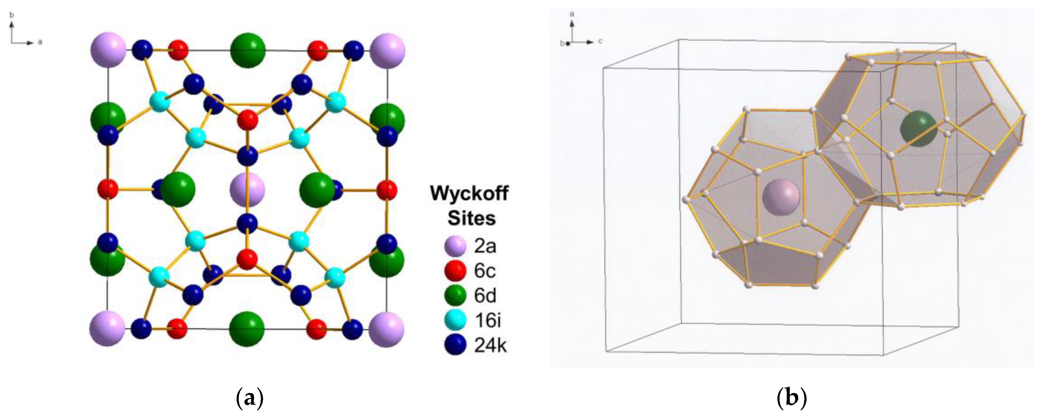
Figure 2.
Cage structure of Type I carbon–silicon clathrate, CySi46-y (a) without guest atoms and (b) with x number of guest atoms A residing within the cage. From Chan et al. [8]. Reprinted with permission from Springer.
Figure 2.
Cage structure of Type I carbon–silicon clathrate, CySi46-y (a) without guest atoms and (b) with x number of guest atoms A residing within the cage. From Chan et al. [8]. Reprinted with permission from Springer.

Figure 3.
Energy change curves for selected Type I clathrate compounds of Ba8CySi46-y, C46, C40Si6, and C23Si23 compared to those of Si46 and Ba8Si46. From Chan et al. [8]. Reprinted with permission from Springer.
Figure 3.
Energy change curves for selected Type I clathrate compounds of Ba8CySi46-y, C46, C40Si6, and C23Si23 compared to those of Si46 and Ba8Si46. From Chan et al. [8]. Reprinted with permission from Springer.

Figure 4.
Computed energy change curves for various C-substituted Type I silicon clathrate frameworks with and without Li, Na, K, and Ba guest atoms. From Chan et al. [8]. Reprinted with permission from Springer.
Figure 4.
Computed energy change curves for various C-substituted Type I silicon clathrate frameworks with and without Li, Na, K, and Ba guest atoms. From Chan et al. [8]. Reprinted with permission from Springer.

Figure 5.
Energy of formation computed via CPMD and VASP for various intermetallic clathrates based on the AxCySi46-y compositions with the hybrid CySi46-y framework: (a) CPMD computations and (b) comparison of CPMD and VASP computations. From Chan et al. [8]. Reprinted with permission from Springer.

Figure 6.
Cage structure of Type I nitrogen–carbon clathrate, NyC46-y, with and without guest atoms: (a) empty NyC46-y and (b) AxNyC46-y with x number of guest atoms A residing within the cage. From Chan et al. [20].
Figure 6.
Cage structure of Type I nitrogen–carbon clathrate, NyC46-y, with and without guest atoms: (a) empty NyC46-y and (b) AxNyC46-y with x number of guest atoms A residing within the cage. From Chan et al. [20].

Figure 7.
Comparisons of computed energy curves and energy of formation for Type I C46, NyC46-y, and AxNyC46-y with various amounts of Li guest atoms as a function of lattice parameter: (a) energy change curve and (b) energy of formation. From Chan et al. [20].
Figure 7.
Comparisons of computed energy curves and energy of formation for Type I C46, NyC46-y, and AxNyC46-y with various amounts of Li guest atoms as a function of lattice parameter: (a) energy change curve and (b) energy of formation. From Chan et al. [20].

Figure 8.
Predicted internal binding energy, lattice constant, and gravimetric capacity of Si46, C6Si40, Na8Al8Si38, and Li8Al8Si38. The range over which binding interactions of H2 is favorable for room-temperature storage is noted as dashed lines: (a) binding energy vs. gravimetric capacity and (b) lattice constant vs. gravimetric capacity. From Chan et al. [22]. The vertical green line indicates DOE’s 2020 system target, while the vertical blue line indicates the DOE ultimate fleet target for onboard storage for vehicles.
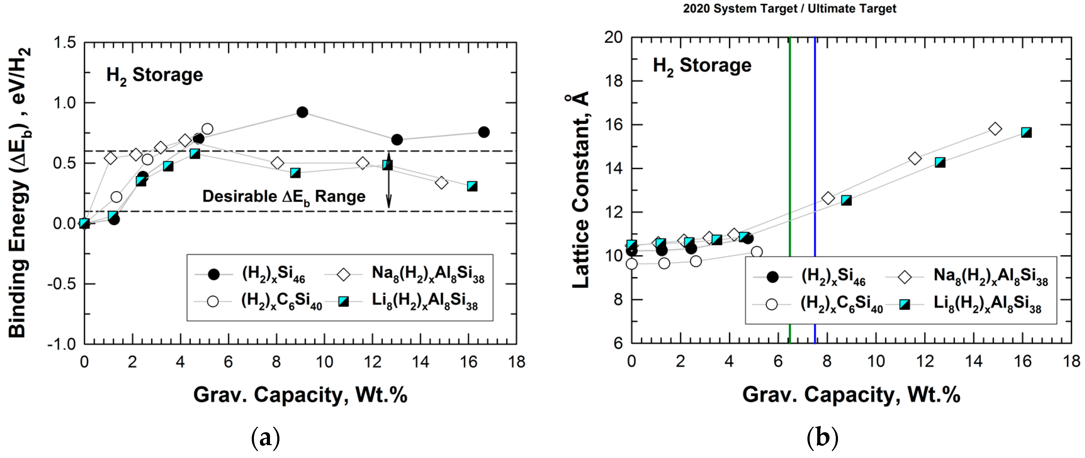
Figure 9.
Predicted volumetric capacity and lattice constant for intermetallic clathrates of Si46, C6Si40, Na8Al8Si38, and Li8Al8Si38. The vertical green line indicates DOE’s 2020 system target, while the vertical blue line indicates the DOE ultimate fleet target for onboard storage for vehicles. The red line indicates the density of liquid hydrogen. From Chan et al. [22].
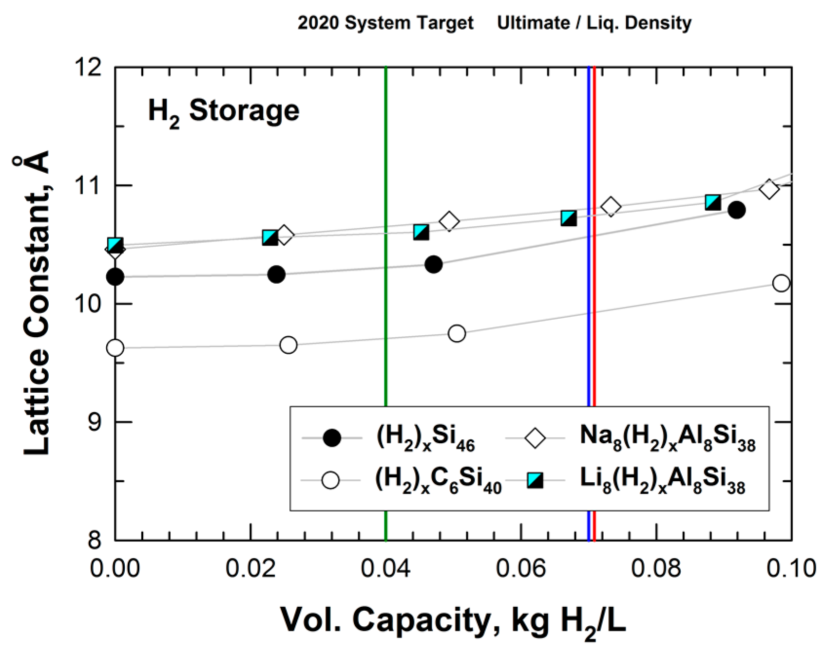
Figure 10.
Electronic band structures of (a) Si46, (b) C6Si40, (c) C12Si34, (d) C23Si23, (e) C34Si12, (f) C40Si6, and (g) C46 predicted by the density functional theory (DFT). (h) The band structure of Si46 predicted using the Hyed–Scuseria–Ernzerhof (HSE) hybrid functional. The corresponding band gaps are denoted. The Fermi level (red dashed line) is referenced at the top of the valence band at zero eV. From Chan and Peng [24]. Reprinted with permission from Springer.

Figure 11.
The total and s–, p–orbital projected density of states of (a) Si46, (b) C6Si46, (c) C23Si23, and (d) C40Si6. The Fermi level (red dashed line) is referenced at the top of the valence band at zero eV. From Chan and Peng [24]. Reprinted with permission from Springer.
Figure 11.
The total and s–, p–orbital projected density of states of (a) Si46, (b) C6Si46, (c) C23Si23, and (d) C40Si6. The Fermi level (red dashed line) is referenced at the top of the valence band at zero eV. From Chan and Peng [24]. Reprinted with permission from Springer.
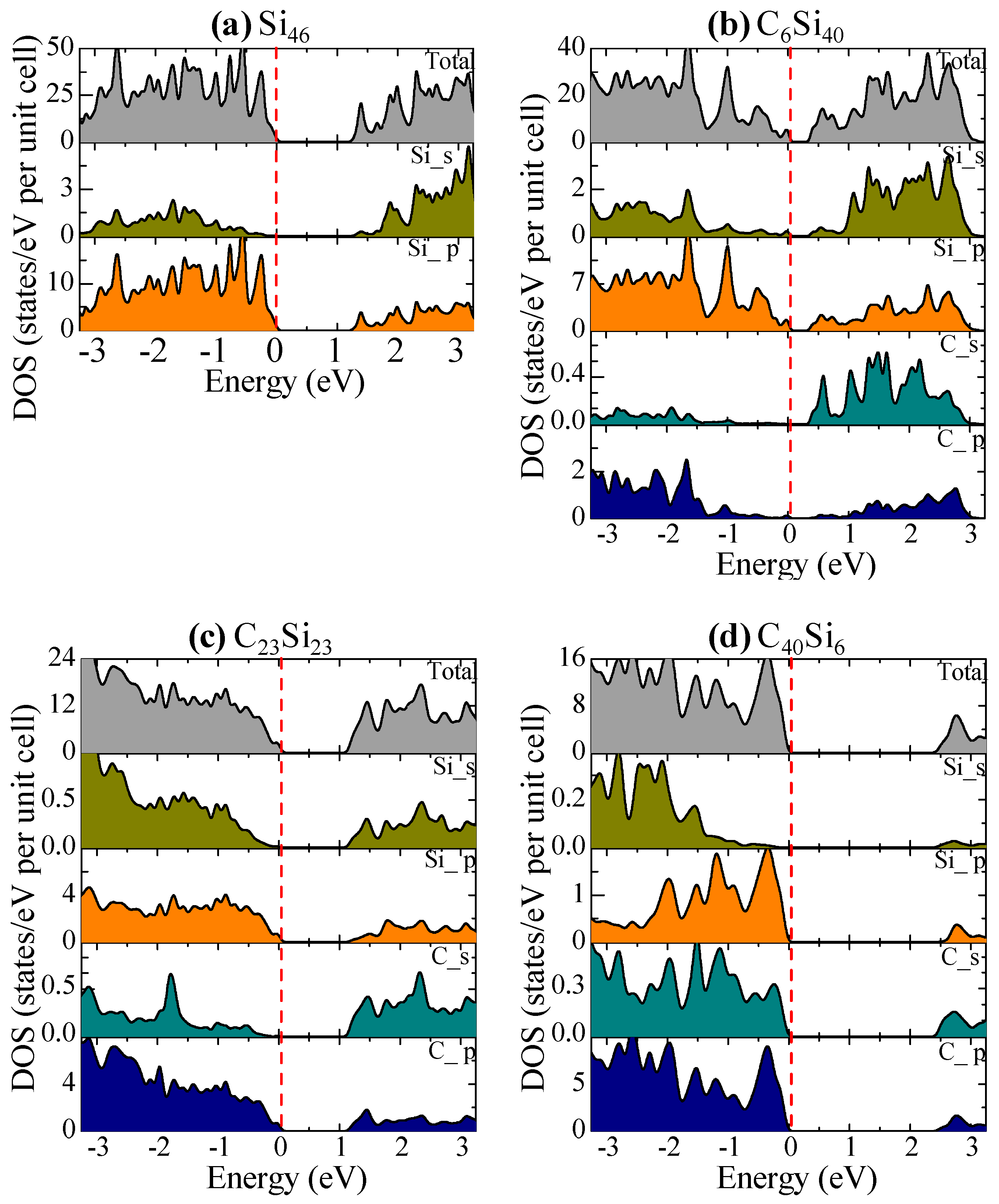
Figure 12.
Computed band gap of CySi46-y as a function of the number of C atoms on the hybrid carbon–silicon framework. The band gap is at a minimum at about C = 6. The dashed line indicates the absence of a band gap and a metal-like conductor at zero band gap. From Chan and Peng [24]. Reprinted with permission from Springer.


Table 1.
Calculated equilibrium volume (V0 in Å3/atom) and lattice parameters (a0, c0 in Å), cohesive energy (Ecoh), and energy of formation (ΔEf) for fcc-C136, sc-C46, hcp-C40, diamond, and graphite at zero pressure, compared to available experimental data for diamond graphite and calculated data for C46 and C136. Modified from Wang et al. [2].
| Structure | Method | V0 (Å3atom) | a0 (Å) | c0 (Å) | Ecoh, eV/Atom | ΔEf, eV/Atom |
|---|---|---|---|---|---|---|
| fcc-C136 | VASP a [2] | 6.601 | 9.647 | −7.709 [2] | 0.074 | |
| DMOL b [6] | 6.688 | 9.689 | N.A. | −7.263 [6] | 0.087 | |
| CPMD c [5] | 0.07 | |||||
| sc-C46 | VASP [2] | 6.543 | 6.702 | N.A. | −7.677 [2] | 0.106 |
| DMOL [6] | 6.604 | 6.722 | N.A | −7.235 | 0.115 | |
| VASP [7] | 6.526 | 6.696 | N.A | 0.09 | ||
| VASP [8] | 6.6973 | 0.08 | ||||
| CPMD [8] | 6.7138 | 0.14 | ||||
| CPMD [5] | 0.09 | |||||
| CRYSTAL95 [9] d | 6.259 | 6.7029 | 0.20 [3] | |||
| hcp-C40 | VASP [2] | 6.609 | 6.695 | 6.809 | −7.656 | 0.127 |
| DMOL [6] | 6.697 | 6.725 | 6.839 | −7.213 | −0.013 | |
| Diamond | VASP [2] | 5.705 | 3.574 | N.A. | −7.783 | 0 |
| DMOL [6] | 5.787 | 3.591 | −7.350 | 0 | ||
| Expt. [10,11] | 5.673 | 3.567 | −7.20 | 0 | ||
| Graphite | VASP [2] | 8.878 | 2.470 | 6.721 | −7.916 | −0.133 |
| DMOL [6] | 8.983 | 2.479 | 6.747 | −7.516 | −0.166 | |
| Expt. [10,11] | 8.803 | 2.662 | 6.708 | −7.40 | −0.20 |
Table 2.
Summary of the computed lattice constant ao and energy of formation ΔEf for Type I carbon clathrate compounds. From Chan et al. [20].
Table 2.
Summary of the computed lattice constant ao and energy of formation ΔEf for Type I carbon clathrate compounds. From Chan et al. [20].
| Compound | ao, Å | ΔEf, eV/Atom |
|---|---|---|
| C46 | 6.6973 | 0.0815 |
| C18N24 | 6.8622 | −0.1377 |
| C19N27 | 6.8148 | 0.1803 |
| C20N26 | 6.8502 | 0.2144 |
| C23N23 | 6.6596 | 0.3416 |
| Li2C18N24 | 7.3192 | −0.25 |
| Li6C18N24 | 7.3336 | −0.2742 |
| Li8C18N23 | 7.3979 | −0.3051 |
| Li8C23N23 | 7.2716 | −0.0578 |
| Li12C18N24 | 8.1592 | −0.5765 |
| Li24C18N24 | 8.6003 | −0.6192 |
| Li48C18N28 | 9.3206 | −0.4832 |
Table 3.
Computed values of the bulk modulus of selected Type I clathrates compared to theoretical and experimental values of the bulk modulus of diamond, carbon nitride, silicon nitride, and silicon carbide from the literature. Experimental values are indicated by an asterisk (*). From Chan et al. [20].
| Compound | Structure | B, GPa |
|---|---|---|
| C46 | Type I Clathrate (Simple cubic) | 373.7 |
| 371 [1] | ||
| 363.7 [2] | ||
| 409 [3] | ||
| C18N24 | Type I Clathrate | 257.35 |
| C23N23 | Type I Clathrate | 311.6 |
| Li8C23N23 | Type I Clathrate | 245.18 |
| Si23C23 | Type I Clathrate | 124.03 |
| Si6C40 | Type I Clathrate | 196.8 |
| Si18N24 | Type I Clathrate | 96.08 |
| Si23N23 | Type I Clathrate | 114.13 |
| C6Si40 | Type I Clathrate | 62.9 |
| C (Diamond) | Diamond cubic | 438.8 [35] |
| 442 * [36] | ||
| α-C3N4 | Hexagonal | 378.7 [35] |
| β-C3N4 | Cubic spinel | 419.1 [36] |
| c-Si3N4 | Cubic spinel | 300 [37] |
| 300 * [38] | ||
| SiC | Cubic (Zinc blend) | 225 * [39] |
Table 4.
Summary of targeted compounds and actual compounds produced by arc-melting. From Chan et al. [8]. Reprinted with permission from Springer.
Table 4.
Summary of targeted compounds and actual compounds produced by arc-melting. From Chan et al. [8]. Reprinted with permission from Springer.
| Composition | Target Compound | Actual Compound Produced | Type I Clathrate | Yield, % |
|---|---|---|---|---|
| 1 | Na2Li6Al10C6Si30 | None (all sublimed except Si) | No | 0 |
| 2 | Li8Al10C6Si30 | Si, SiC, and AlLiSi | No | 0 |
| 3 | Ba8C6Si40 | BaSi2, Si, and graphite | No | 0 |
| 4 | Ba8C20Si26 | Ba, SiC, BaSi2, Si, and Ba8C20Si26 | Yes (Ba8C20Si26) | 39 |
| 5 | Ba8C6Si40 | Ba, SiC, BaSi2, Si, and Ba8C6Si40 | Yes (Ba8C6Si40) | 26 |
| 6 | Ba8C23Si23 | Ba, SiC, BaSi2, Si, and Ba8C23Si23 | Yes (Ba8C23Si23) | 16 |
Table 5.
Summary of targeted compounds and actual compounds produced by arc-melting From Chan et al. [20].
Table 5.
Summary of targeted compounds and actual compounds produced by arc-melting From Chan et al. [20].
| Composition | Target Compound | Actual Compound Produced | Type I Clathrate |
|---|---|---|---|
| 1 | Mg8N18C28 | MgO, g-C2N4, and MgCN2 | No |
| 2 | Ba8N18C24 | Ba, g-C3N4, and Ba8C18N24 | Yes (Ba8C18N24) |
© 2018 by the author. Licensee MDPI, Basel, Switzerland. This article is an open access article distributed under the terms and conditions of the Creative Commons Attribution (CC BY) license (http://creativecommons.org/licenses/by/4.0/).
Share and Cite
MDPI and ACS Style
Chan, K.S. Hybrid Carbon-Based Clathrates for Energy Storage. C 2018, 4, 7. https://doi.org/10.3390/c4010007
AMA Style
Chan KS. Hybrid Carbon-Based Clathrates for Energy Storage. C. 2018; 4(1):7. https://doi.org/10.3390/c4010007
Chicago/Turabian StyleChan, Kwai S. 2018. "Hybrid Carbon-Based Clathrates for Energy Storage" C 4, no. 1: 7. https://doi.org/10.3390/c4010007
Note that from the first issue of 2016, this journal uses article numbers instead of page numbers. See further details here.