Supercapacitor Electrode Based on Activated Carbon Wool Felt
by
 and
and
Ana Claudia Pina
1,*, 
Alejandro Amaya
1,
Jossano Saldanha Marcuzzo
2,
Aline C. Rodrigues
3,
Mauricio R. Baldan
2,
Nestor Tancredi
1 and
Andrés Cuña
1 1
Área Fisicoquímica, DETEMA, Facultad de Química, Universidad de la República, Montevideo 11200, Uruguay
2
Instituto Nacional de Pesquisas Espaciais—INPE, São José dos Campos 12227-010, Brazil
3
Instituto Tecnológico de Aeronáutica—ITA, São José dos Campos 12228-900, Brazil
*
Author to whom correspondence should be addressed.
C 2018, 4(2), 24; https://doi.org/10.3390/c4020024
Submission received: 1 March 2018
/
Revised: 9 April 2018
/
Accepted: 11 April 2018
/
Published: 16 April 2018
(This article belongs to the Special Issue Carbon Materials in Environment Protection & Selected Papers from CESEP2017)
Abstract
:An electrical double-layer capacitor (EDLC) is based on the physical adsorption/desorption of electrolyte ions onto the surface of electrodes. Due to its high surface area and other properties, such as electrochemical stability and high electrical conductivity, carbon materials are the most widely used materials for EDLC electrodes. In this work, we study an activated carbon felt obtained from sheep wool felt (ACF’f) as a supercapacitor electrode. The ACF’f was characterized by elemental analysis, scanning electron microscopy (SEM), textural analysis, and X-ray photoelectron spectroscopy (XPS). The electrochemical behaviour of the ACF’f was tested in a two-electrode Swagelok®-type, using acidic and basic aqueous electrolytes. At low current densities, the maximum specific capacitance determined from the charge-discharge curves were 163 F·g−1 and 152 F·g−1, in acidic and basic electrolytes, respectively. The capacitance retention at higher current densities was better in acidic electrolyte while, for both electrolytes, the voltammogram of the sample presents a typical capacitive behaviour, being in accordance with the electrochemical results.
1. Introduction
In recent decades electrochemical capacitors, also known as supercapacitors, have received great scientific and technological attention because of their interesting possibilities as energy storage devices [1,2]. Although different commercial devices already exist, there are still many scientific and technological challenges in the supercapacitor research area, mainly with respect to increasing the amount of stored energy [2]. Given their suitable characteristics for supercapacitor electrode application, carbon materials have received the most attention and they are the most widely used in this application [3,4,5,6,7,8,9,10,11,12]. Within carbon materials, carbon fibres (CF) have special characteristics when compared with other carbon materials [13]. The CF can also be transformed into fabric, woven or yarn forms, which give them self-sustainable characteristics. The CF may have a high surface area with a well-defined pore structure, good electrical conductivity, and easy electrode formation and containment [14]. The study and production of CF, as well as activated carbon fibres (ACF), are of particular interest among different research groups due to their several applications in a wide range of fields from science to industry. These materials have chemical, electrical, and mechanical properties that make them unique; therefore, the demand for this kind of material is expected to increase in the future. The use of ACF have been extended to multiple processes based on adsorption and catalysis, such as gas separation, wastewater purification, advanced oxidation processes, and supercapacitors [15,16,17,18,19]. Nowadays the CF, as well as ACF, production is based on the use of petroleum derivatives as precursor materials, which implies high-energy demands and a major contribution to the carbon footprint [20,21]. These problems could be minimized by using a precursor material from a renewable source; many studies had already used biomass as an ACF precursor, and in other cases natural fibres, such as silk, jute, cotton, or bamboo, have been used [22,23,24,25,26]. Among natural fibre sources wool is one of the main examples, a large quantity of waste is generated among the major wool producer countries, creating a final disposal problem because of their quite slow biodegradability. Therefore, the use of this waste as an ACF precursor is quite interesting because of their availability and low cost, besides being a renewable and environmentally friendly material. In addition, what makes wool more suitable in comparison with other bio-based sources is its high carbon content (47%) and the presence of sulphur (3.4%), these two factors combined will enhance the carbon fibre yield during the thermal treatment.
Until now, Marcuzzo et al. [27] performed the only previous experience reported on the obtaining of ACF from wool felt. There are previous works with wool; Chen et al. produced activated carbon powder by chemical activation, obtaining a small specific area for an activated carbon material, while Hassan et al. studied the best conditions to obtain CF from wool.
In this work, we reported the preparation and characterization of activated carbon wool felt (ACF’f) as a supercapacitor electrode. This activated carbon material was characterized by textural and chemical analysis, and its performance as a supercapacitor electrode was evaluated through galvanostatic charge-discharge curves, cyclic voltammetries, and electrochemical impedance spectroscopy using basic and acidic electrolytes.
2. Materials and Methods
2.1. Activated Carbon Felt Preparation
A temperature controlled Carbolite furnace (Carbolite Furnaces, Sheffield, UK) was used to convert the wool felt into ACF’f. The samples were prepared according to Marcuzzo et al. [27], the commercial sheep wool felt were cut in regular pieces (100 × 30 mm). For achieving fibre stabilization, the felt was heated up at 10 °C·min−1 under a constant airflow (100 mL·min−1) up to 300 °C and kept under these conditions for 120 min. Then, the samples were heated at 10 °C·min−1 under a constant nitrogen gas flow (100 mL·min−1) up to a temperature of 800 °C and kept there for 30 min; at this stage, the pyrolysis took place. Finally, the samples were heated at 10 °C·min−1 up to 1000 °C where activation took place by injecting water in a 1:1 (carbon felt—water) mass relation. After cooling the furnace under a constant nitrogen flow (100 mL·min−1), the ACF’f was removed and placed in a desiccator. All reactants employed were analytical grade (Lynde Group). The samples were named according to the thermal process to which they were exposed: “Felt” for the raw material, “Oxidized” for the stabilized sample, “Ox/Carbonized” for the stabilized and carbonized sample, and “ACF’f” for the activated carbon felt.
2.2. Scanning Electron Microscopy (SEM)
The surface and structural characteristics of the wool felt and the ACF’f were assessed by scanning electron microscopy. Electronic images of the samples were obtained with a JEOL JSM 5900L microscope (JEOl LCC, Peabody, MA, USA). The SEM images of the ACF’f were performed without any conductive coating, as the samples were conductive enough to prevent electrical discharge.
2.3. Chemical and Electrochemical Characterizations
The ACF’f and the intermediate products were characterized by elemental analysis in a Thermocientific Flash 2000 Elemental Analyser (Thermo Fisher Scientific Inc., Waltham, MA, USA). Textural analysis was carried out in a Beckman Coulter analyser (Beckman Coulter, Brea, CA, USA), at 77 K, after degassing the samples at 100 °C for 10 h. Brunauer-Emmett-Teller (BET) area, Dubinin-Radushkevich micropore volume, and total pore volume (measured at relative pressure of 0.995) were obtained, as well as the pore size distribution through the non-local density functional theory (NLDFT) method. X-ray photoelectron spectroscopy (XPS) is a powerful method for the investigation of surface chemistry. All the XPS measurements were carried out with a Kratos Axis Ultra XPS spectrometer (Kratos Analytical Ltd., Manchester, UK) using monochromatic Al–K alpha (1486.5 eV) X-ray radiation at a power of 15 kV at 150 W. The emitted photoelectrons were detected using a hemispherical analyser (Kratos Analytical Ltd., Manchester, UK) and 15 µm-spatial resolution. The vacuum system was maintained at approximately 10−9 Torr during all the experiments. Survey scans were collected from zero to 1200 eV with 160 eV pass energy and step size of 1 eV, in order to identify the elements present on the surface. High-resolution detection of specific elements were performed with a pass energy of 40 eV. The peaks deconvolution analyses were obtained by software CasaXPS (Casa Software Ltd., Teignmouth, UK).
For the electrochemical analysis, two-electrode Swagelok®-type cells having two tantalum rods as current collectors were used for galvanostatic charge/discharge and cyclic voltammetry measurements. A glassy microfiber paper (Whatman 934 AH) was chosen as a separator. The samples used as electrodes had a cross-section area of 0.5 cm2 and thickness of 0.10 cm. The weight of the electrodes was between 6.4 mg and 7.6 mg. The gravimetric specific capacitance (Cs) was determined from galvanostatic charge/discharge measurements in the voltage range of 0–1.0 V at current densities in the range of 1–100 cm−2. Cs was determined at each current according to the Equation (1):
Cs = 2·I·td/E2·me
In the Equation (1), I is the applied current, td is the discharge time, E2 is the voltage range during the discharge, and me is the mass of one electrode. Cyclic voltammograms were obtained at room temperature in the range 0–1.0 V at different scan rates (10, 20, and 50 mV·s−1). Electrochemical impedance spectroscopy (EIS) measurements were carried out in the frequency range from 10−4 to 105 Hz with perturbation of sinusoidal amplitude of 30 mV (rms) and 10 points per frequency.
All measurements were carried out at room temperature by a PGSTAT 302N Autolab potentiostat/galvanostat (Utrecht, The Netherlands), using 2.0 mol·L−1 H2SO4 and 6.0 mol·L−1 KOH aqueous solution as the electrolyte. In order to improve de electrolyte infiltration, before the cell assembly, the electrodes were soaked in the electrolyte for 24 h.
3. Results and Discussion
3.1. Sample Obtention
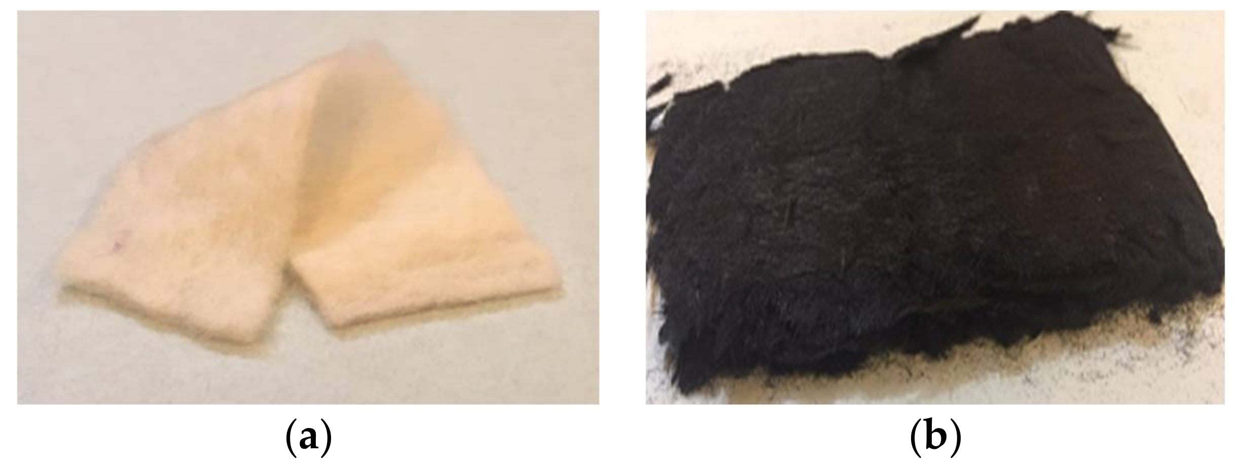
For this work a commercial felt was used as precursor (Figure 1a). After the thermal treatment, an ACF’f was obtained (Figure 1b) the material retains the structural integrity in terms of its manipulation, however, it is less resistant than the original material. It is presumed that the presence of sulphur found in the disulphide bonds is responsible for the high mechanical strength, which allows the fibre to keep its morphology during the thermal treatment. However, the ACF’f shows poor tensile strength and elongation at break compared to any commercial carbon fibre.
3.2. SEM Microscopy
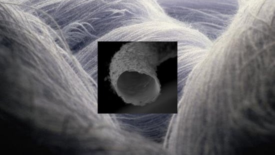
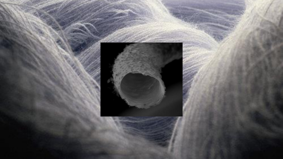
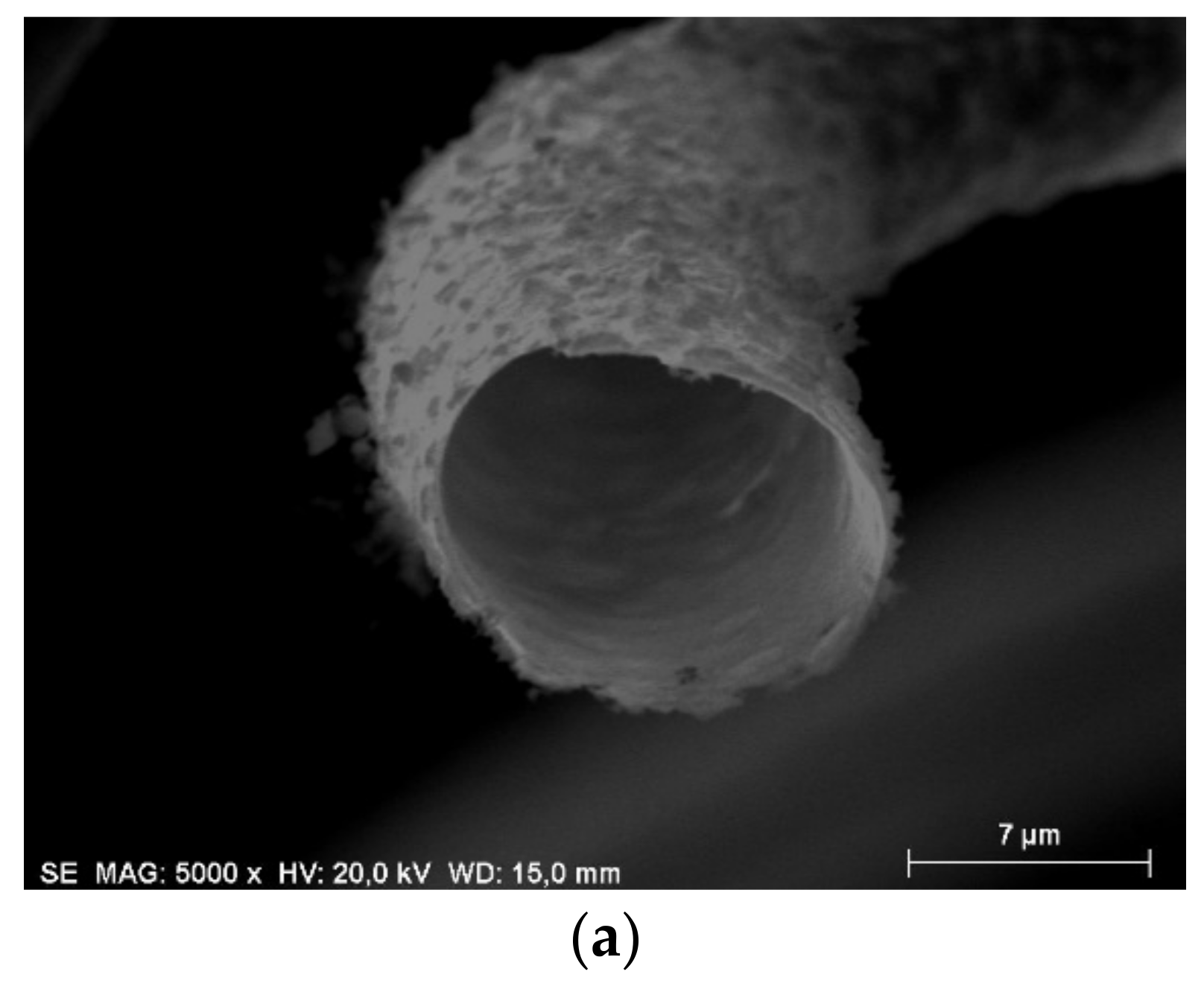
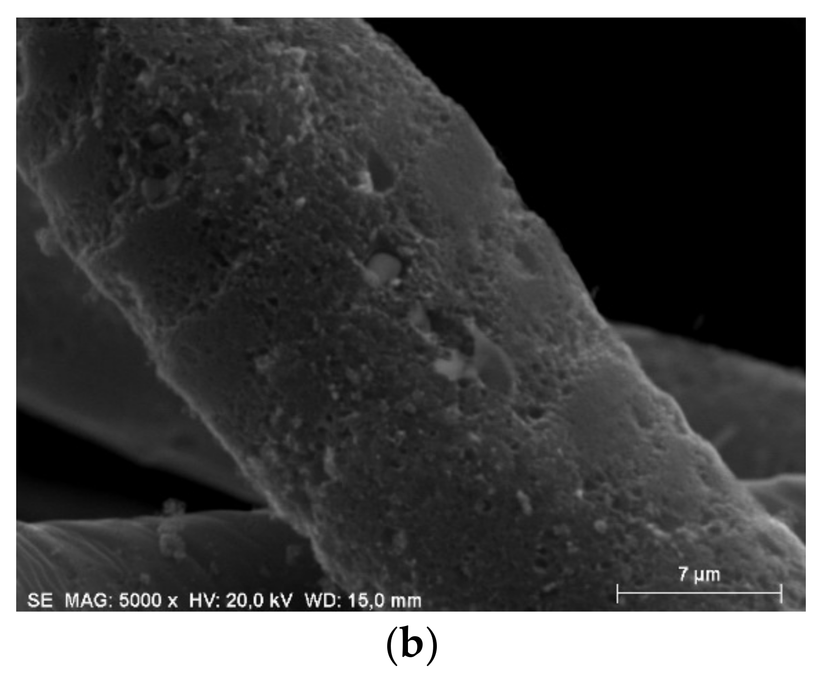
The SEM image of the wool felt (Figure 2a) clearly shows the external cuticle layer, with overlapping scales. The cuticle layer represents about 10% of the fibre, while the cortex forms the rest of the structure. It can be observed that the scaly structure of the cells is not so well defined for the stabilized sample (Figure 2b), as well as part of the cortex was lost. Finally, the ACF’f (Figure 3a) presents a tubular structure without the presence of the cortex while the surface lost its characteristic scaly appearance (Figure 3b).
3.3. Elemental Analysis
Elemental analysis (Table 1), carried out on the different samples showed that the carbon is the major component in all cases. Although the carbon content of wool is lower than in other materials, like lignin (63.4%) or polyacrylonitrile known as PAN (67.91%), this material presents the advantage of being rich in sulphur, responsible for the structure integrity of the fibre. Carbon content increases after stabilization and carbonization due to selective volatilization of non-carbon components. This behaviour is expected, since the carbonization involves thermal decomposition eliminating non-carbon species and producing a fix carbon mass with a rudimentary pore structure, and that is the reason for the carbon percentage increase, to decrease later during activation because of the removal of the disorganized carbon. After the stabilization, the sulphur content does not change, which allows hypothesising that the functional groups containing sulphur remain stable during the rest of the thermal treatment.
3.4. Textural Analysis
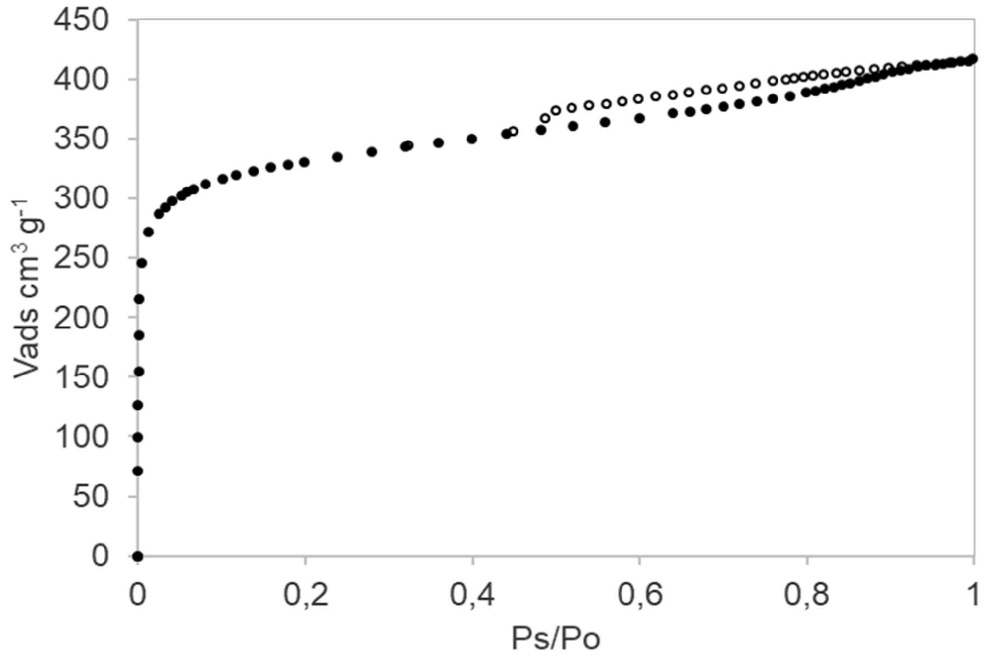
ACF’f N2 adsorption-desorption isotherms (Figure 4) present type IV behaviour according to BDDT classification [28], indicating a strong presence of micropores and a proportion of mesopores. BET area was determined in the relative pressure range of 0.03–0.3 was of 1140 m2·g−1, micropore volume was 0.37 cm3·g−1 and total pore volume was 0.64 cm3·g−1, values similar to those reported by Marcuzzo et al. [27]. The pore size assessment results obtained through NLDFT method demonstrate that most of the pores have diameters thinner than 2.0 nm, while the presence of hysteresis indicates filling and emptying of the mesopores by capillary condensation [29]. The ACF’f presents a higher specific surface area comparing with the area obtained by Chen et al. (438 m2·g−1); therefore, physical activation demonstrate being more effective for the pore development than chemical activation. The material is conformed by microporous activated carbon hollow fibres with different content on their surface of oxygenated functional groups.
3.5. X-ray Photoelectron Spectroscopy
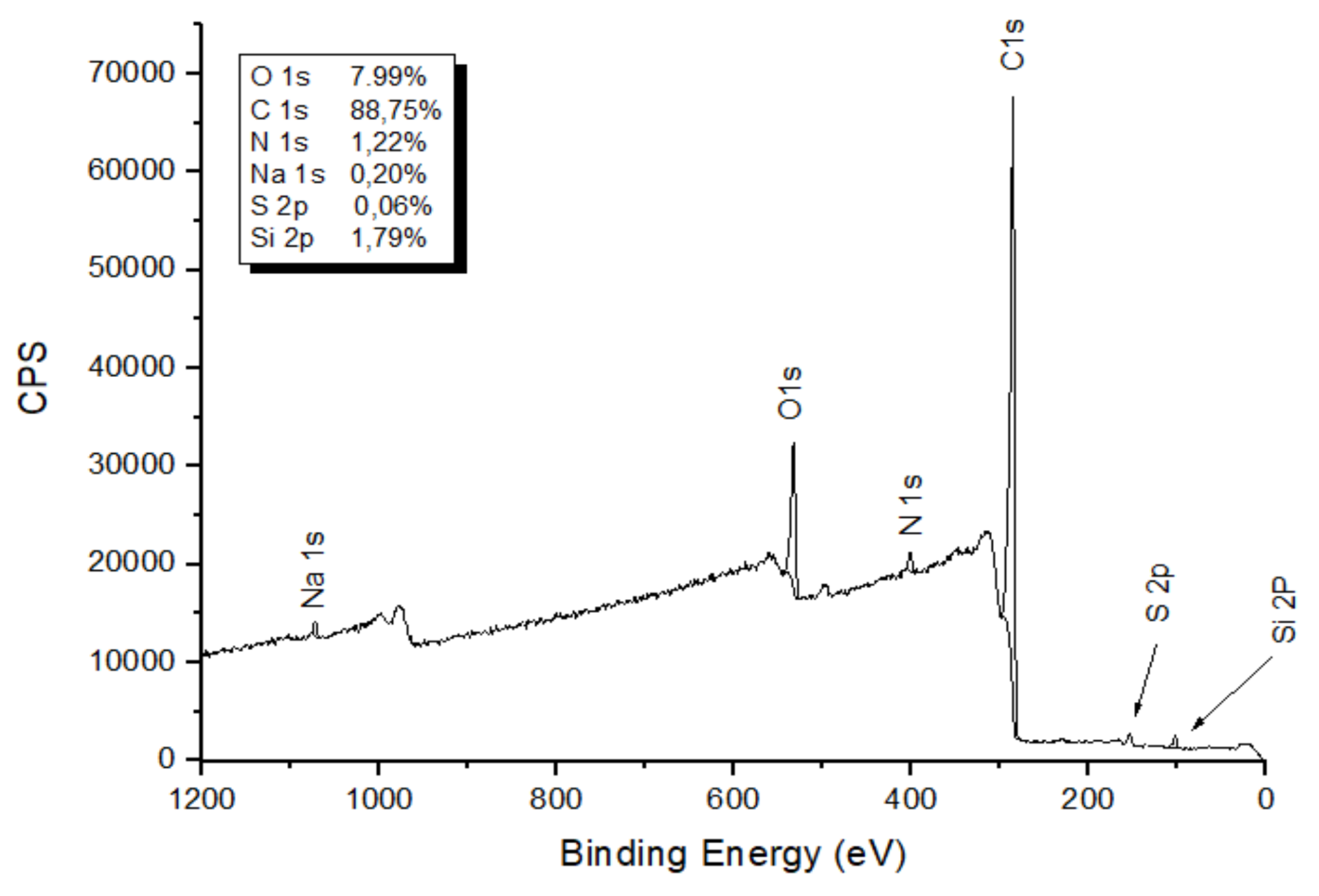
In order to obtain information about chemical composition of the ACF’f and binding characteristics of the surface material elements, XPS measurements were analysed (Figure 5). Quantitative analysis shows a surface composition of 88.75 at % C 1s, 7.99 at % O 1s as expected, and, small peaks of Na 1s, S 2p, N 1s and Si 2p can be found. On the other hand, the presence of Si 2p was detected despite being an element not common for sheep wool; therefore, it can be concluded that the responsible source for this element is the quartz furnace tube.
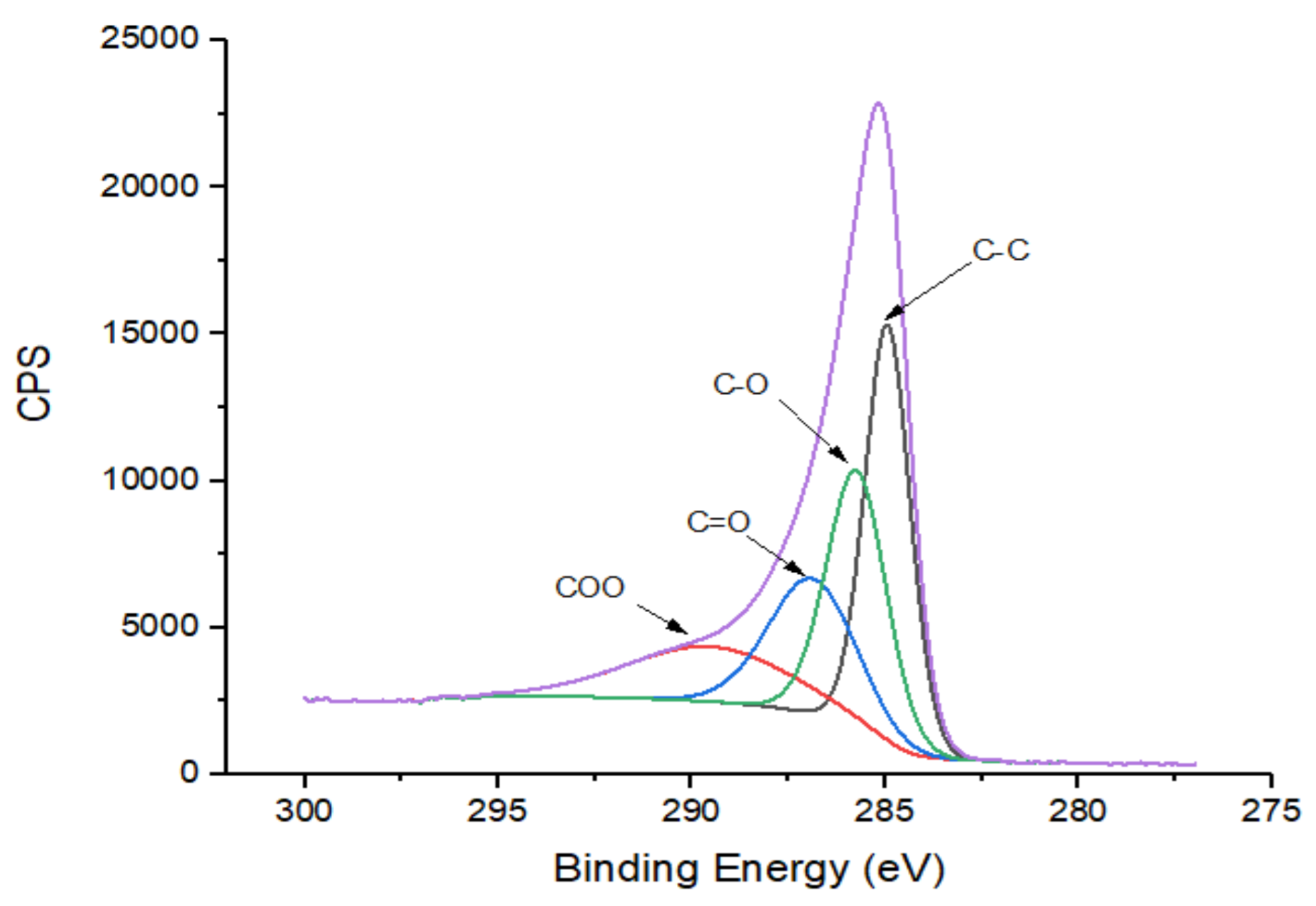
More information on nature of the functional radicals may be obtained from high-resolution XSP analysis. High-resolution C 1s spectra (Figure 6) indicate different types of chemical bonding for C 1s atoms, especially oxygen groups that are usually reported in the literature. The binding energy from 284.6 to 285.1 eV is associated to carbon sp2; 286.3 to 287.0 eV is related to ether or alcohol groups (C–O); 287.5 to 288.1 eV is related to quinine or/and carbonyl groups (C=O) and, finally, carboxyl groups (COO) with a binding energy between 291.2 and 292.1 eV [30].
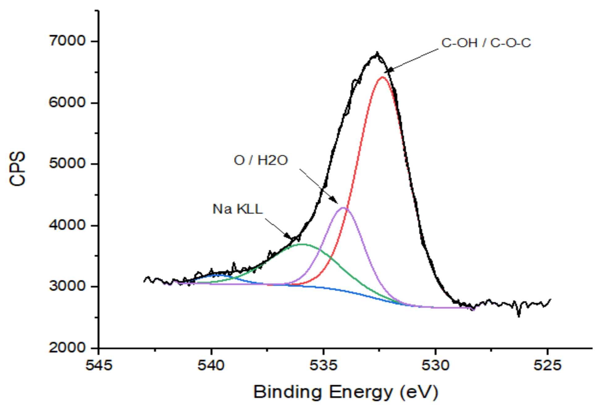
The high energy-resolution O 1s spectra deconvolution shows two main peaks. Binding energy from 532.4 to 533.1 eV is associated to C–OH and/or C–O–C; the energy between 534.8 and 535.6 eV report the presence of oxygen quimisorbed and water (Figure 7) [31].
The high-resolution N 1s spectra show a main peak near 401.0 eV that can be associated with the N–H bond (Figure 8) [32].
As presented, the XPS analyses shows the presence of several types of oxygen, as well as nitrogenous bases, these kind of surface chemistry are normally connected to pseudocapacitive behaviour of some carbon materials [11].
3.6. Electrochemical Analysis
3.6.1. Charge-Discharge Curves
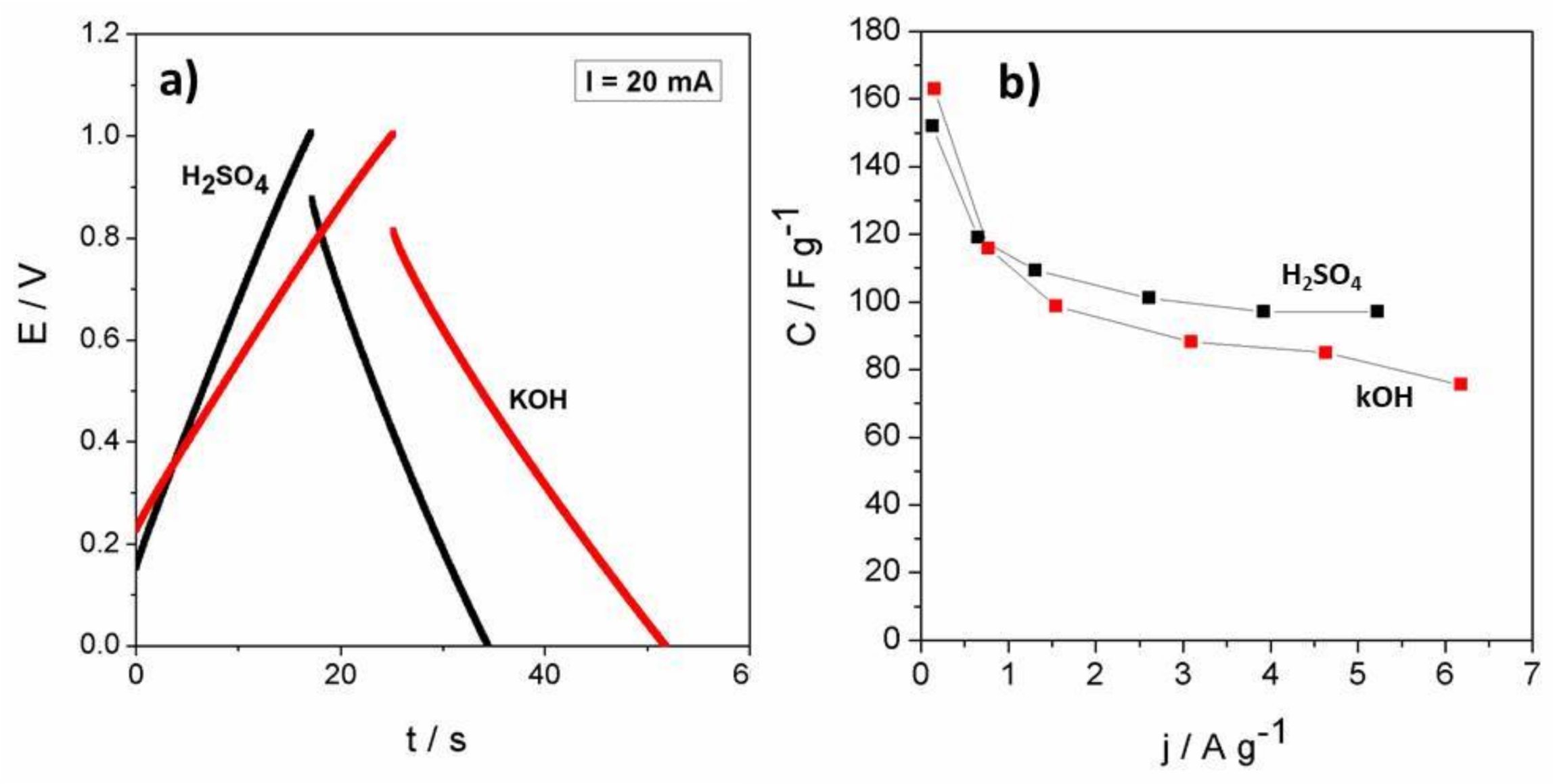
The next graph (Figure 9a), shows the charge-discharge curve obtained at a constant current of 20 mA in acidic and basic electrolytes. The curves have the typical triangular shape of capacitive materials. The equivalent series resistance (ESR), which represents the sum of the resistances of the cell, can be determined from the voltage drop (E1) at the beginning of the discharge as ESR = E1/2I [1,33]. At a current of 20 mA the determined ESR were ~3 Ω and ~9 Ω in acidic and basic electrolytes, respectively. This represents a weakness for the basic electrolyte since the higher the ESR, the lower the capacitance retention at high current and the power capability of the cell [1,33,34]. The Cs vs. the specific current is shown in the next graph (Figure 9b). The capacitance retention at higher current densities was better in the acidic electrolyte, which is in agreement with what was already discussed for ESR values. The ACF’f presents a moderate Cs in both electrolytes with a maximum Cs value of 163 F·g−1 and 152 F·g−1 obtained at 0.15 A·g−1 in basic and acidic electrolytes, respectively. These values are higher or comparable with some other previously reported Cs values for carbon fibre materials [19,35,36], biomass-derived carbon materials [9,10], and other types of carbonaceous materials [3]. However, the determined Cs for ACF’f are lower than those reported for several metal oxides [37,38] and conducting polymer-based materials [39,40]. Notwithstanding, the results achieved are in accordance with the high specific surface area of the ACF’f sample, which would determine a high double layer capacitance for this carbon material. On the other hand, the presence of oxygenated and nitrogenated surface functional groups in the sample, which were confirmed in the elemental and XPS analysis, can enhance the observed Cs through reversible redox reactions (pseudocapacitance contribution). This phenomenon could explain the fact that the observed Cs was slightly higher than expected for this material if it were purely capacitive. For carbon materials without a pseudocapacitive contribution, the observed Cs is only related to the double layer capacitance which can be estimated according to the following Equation (2):
where Cdl is the expected double layer capacitance in F·g−1, 0.1 is the normalized area capacitance for a carbon material in aqueous electrolyte expressed in F·m−2, and SSA is the specific surface area of the electrode material in m2·g−1. Thus, in accordance with the BET SSA of the ACF’f sample, the value of Cdl was expected to be 115 F·g−1, which, in fact, is lower than the Cs values determined in acidic (152 F·g−1) and basic electrolytes (163 F·g−1). Therefore, taking into account everything discussed so far, it is reasonable to think that the sample presents some pseudocapacitive contribution to the observed Cs.
Cdl = 0.1 × SSA
3.6.2. Voltammograms
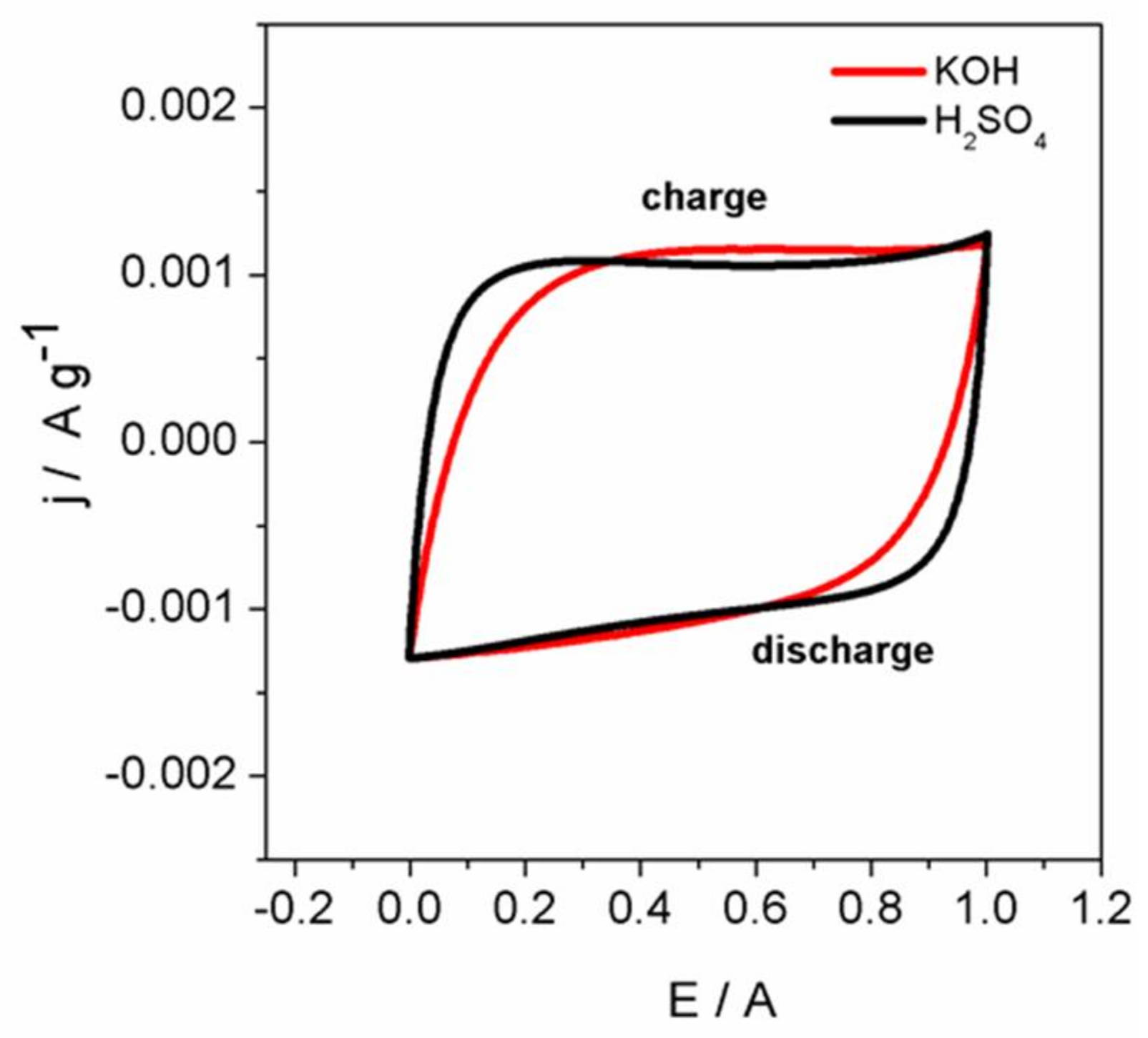
The cyclic voltammograms (Figure 10), demonstrate that, in both electrolytes, the ACF’f show a typical capacitive behaviour and agrees with the galvanostatic analysis. Peaks related with reversible redox reactions are not clearly shown in the voltammograms, but a pseudocapacitive contribution cannot be discarded. For suitable visualization of this type of contribution, it would be more convenient to perform the potentiometric study in a three-electrode configuration [1,33]. Furthermore, it can also be clearly seen that the voltammogram obtained in the basic electrolyte presents a lower slope at the beginning of the charge or discharge compared to that obtained with the acidic electrolyte. This behaviour may be due to the greater ESR of the cell using basic electrolyte.
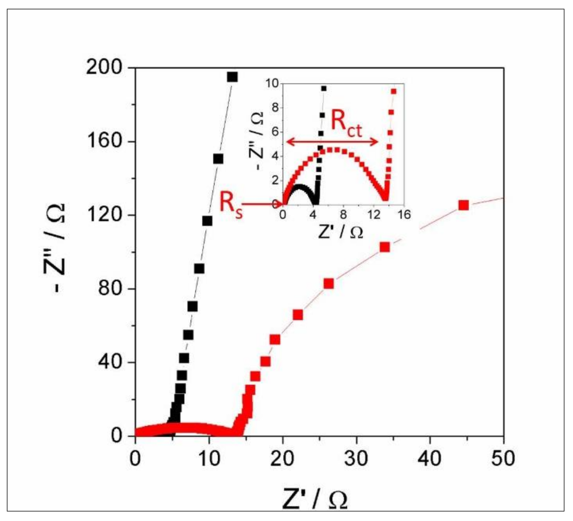
The next graph (Figure 11) shows the Nyquist plot obtained for the EIS experiments. The sample analysed using acidic electrolyte shows high capacitive behaviour, which is evidenced by the vertical-shaped line at low frequencies [41]. In contrast, the sample analysed using basic electrolyte shows a more inclined line at low frequencies. The series resistance (Rs) found at high frequency (see the inset of the Figure 11), related to the bulk-solution resistance and electronic resistance of the electrode, is low and very similar in both electrolytes, 0.23 and 0.34 Ω for basic and acidic electrolyte, respectively. This is consistent with a high electrical conductivity of the ACF’f. Charge transfer resistance (Rct), associated with the charge transfer across the electrode-electrolyte interface, can be determined from the width of the semi-circle that appears at high frequencies [1,33,34] (see the inset of the Figure 11). Rct was higher in the basic electrolyte than in the acidic one, which can be related to a higher pseudocapacitive contribution (already discussed above) in the basic electrolyte. In both electrolytes, the total resistance (Rs + Rct) value is in good agreement with the ESR value determined from the galvanostatic experiments. These values are similar to other carbon materials used as supercapacitor electrodes [34].
4. Conclusions
A wool derived ACF’f was successfully prepared and characterized as a supercapacitor electrode. The material presents a good BET specific surface area, according to a hollow fibre, and a heterogeneous surface chemical composition. This heterogeneity is supported by the elemental and XPS analysis results, suggesting the presence of nitrogenated and oxygenated functional groups. The ACF’f has a moderate Cs value in both electrolytes with a maximum of 163 F·g−1 in KOH-based electrolyte and 152 F·g−1 in H2SO4-based electrolyte, both determined at 0.15 A·g−1. On the other hand, the ACF felt has a higher capacitance retention and lower ESR when the used electrolyte was the sulphuric acid aqueous solution in comparison with the basic one. In sum, this work shows that wool-derived ACF’f can be a promising low-cost and environmentally friendly material for supercapacitor electrode applications.
Future works are going to be focalized in completing the electrochemical characterizations, mainly carrying out studies of cyclability and the electrochemistry performance using organic electrolytes. Furthermore, thinking of a possible commercial application, it could be interesting to design modifications in the fibre structure in order to decrease the electrical resistance.
Author Contributions
Ana Claudia Pina, Alejandro Amaya, and Jossano Saldanha Marcuzzo conceived, designed, developed, characterized, and analysed the data corresponding to the material; Andrés Cuña and Jossano Saldanha Marcuzzo conceived and designed the electrochemical experiment; Aline C. Rodrigues developed the experiment; Andrés Cuña analysed the electrochemical data; Mauricio R. Baldan and Nestor Tancredi contributed with analysis tools; and Aline C. Rodrigues, Andrés Cuña, and Jossano Saldanha Marcuzzo wrote the paper.
Conflicts of Interest
The authors declare no conflict of interest.
References
- Béguin, F.; Frąckowiak, E. Supercapacitors: Materials, Systems, and Applications; Wiley-VCH Verlag GmbH & Co.: Weinheim, Germany, 2013. [Google Scholar]
- González, A.; Goikolea, E.; Barrena, J.A.; Mysyk, R. Review on supercapacitors: Technologies and materials. Renew. Sustain. Energy Rev. 2016, 58, 1189–1206. [Google Scholar] [CrossRef]
- Centeno, T.A.; Hahn, M.; Fernández, J.; Kotz, R.; Stoeckli, F. Correlation between capacitances of porous carbons in acidic and aprotic EDLC electrolytes. Electrochem. Commun. 2007, 9, 1242–1246. [Google Scholar] [CrossRef] [Green Version]
- Ujjain, S.K.; Ahuja, P.; Bhatia, R.; Attri, P. Printable multi-walled carbon nanotubes thin film for high performance all solid state flexible supercapacitors. Mater. Res. Bull. 2016, 83, 167–171. [Google Scholar] [CrossRef]
- Savilov, S.V.; Strokova, N.E.; Ivanov, A.S.; Arkhipova, E.A.; Desyatov, A.V.; Hui, X.; Aldoshin, S.M.; Lunin, V.V. Nanoscale carbon materials from hydrocarbons pyrolysis: Structure, chemical behavior, utilization for non-aqueous supercapacitors. Mater. Res. Bull. 2015, 69, 13–19. [Google Scholar] [CrossRef]
- Dolah, B.N.M.; Deraman, M.; Othman, M.A.R.; Farma, R.; Taer, E.M.; Awitdrus, A.; Basri, N.H.; Talib, I.A.; Omar, R.; Nor, N.S.M. A method to produce binder less supercapacitor electrode monoliths from biomass carbon and carbon nanotubes. Mater. Res. Bull. 2014, 60, 10–19. [Google Scholar] [CrossRef]
- Xi, S.; Kang, Y.; Qu, S.; Han, S. Flexible supercapacitors on chips with interdigital carbon nanotube fiber electrodes. Mater. Lett. 2016, 175, 126–130. [Google Scholar] [CrossRef]
- Shen, H.; Liu, E.; Xiang, X.; Huang, Z.; Tian, Y.; Wu, Y.; Wu, Z.; Xie, H. A novel activated carbon for supercapacitors. Mater. Res. Bull. 2012, 47, 662–666. [Google Scholar] [CrossRef]
- Cuña, A.; Tancredi, N.A.; Bussi, J.; Deiana, A.C.; Sardella, M.-F.; Barranco, V.; Rojo, J.M. Eucaliptus grandis as a biocarbon precursor for supercapacitor electrode application. Waste Biomass Valoriz. 2014, 5, 305–313. [Google Scholar] [CrossRef]
- Cuña, A.; Ortega, M.R.; da Silva, E.L.; Tancredi, N.; Radtke, C.; Malfatti, C.F. Nitric acid functionalization of carbon monoliths for supercapacitors: Effect on the electrochemical properties. Int. J. Hydrogen Energy 2016, 41, 12127–12135. [Google Scholar] [CrossRef]
- Pandolfo, A.G.; Hollenkamp, A.F. Carbon properties and their role in supercapacitors. J. Power Sources 2006, 157, 11–27. [Google Scholar] [CrossRef]
- Solano, A.L.; Carzola-Amorós, D. Adsorption on Activated Carbon Fiber: Adsorption by Carbons; Elsevier: New York, NY, USA, 2008; pp. 431–454. [Google Scholar]
- Newcomb, B.A. Processing, structure, and properties of carbon fibers. Compos. Part A Appl. Sci. Manuf. 2016, 91, 262–282. [Google Scholar] [CrossRef]
- Edie, D.D. The effect of processing on the structure and properties of carbon fibers. Carbon 1998, 4, 345–362. [Google Scholar] [CrossRef]
- Pickering, A.K.; Efendi, M.; Le, T. A review of recent developments in natural fiber composites and their mechanical performance. Compos. Part A Appl. Sci. Manuf. 2016, 83, 98–112. [Google Scholar] [CrossRef] [Green Version]
- Wang, P.; Lang, J.; Xu, S.; Wang, X. Nitrogen-containing activated carbon fibers derived from silk fibers for CO2 capture. Mater. Lett. 2015, 152, 145–147. [Google Scholar] [CrossRef]
- Lee, H.-M.; Kwac, L.-K.; An, K.-H.; Park, S.-J.; Kim, B.-J. Electrochemical behavior of pitch-based activated carbon fibers for electrochemical capacitors. Energy Conver. Manag. 2016, 125, 347–352. [Google Scholar] [CrossRef]
- Li, T.; Zhang, W.; Zhi, L.; Yu, H.; Dang, L.; Shi, F.; Xu, H.; Hu, F.; Liu, Z.; Lei, Z.; et al. High energy asymmetric electrochemical capacitors based on oxides functionalized hollow carbon fibers electrodes. Nano Energy 2016, 30, 9–17. [Google Scholar] [CrossRef]
- Marcuzzo, J.S.; Cuña, A.; Tancredi, N.; Mendez, E.; Bernardi, H.H.; Baldan, M. Microporous activated carbon felt from Brazilian textile PAN fiber: Preparation, characterization and application as super capacitor electrode. Rev. Bras. Apliçacões Vácuo 2016, 35, 58–63. [Google Scholar] [CrossRef]
- Hassan, M.M.; Schiermeister, L.; Staiger, M.P. Sustainable Production of Carbon Fiber: Effect of Crosslinking in Wool Fiber on Carbon Yields and Morphologies of Derived Carbon Fiber. ACS Sustain. Chem. Eng. 2015, 311, 2660–2668. [Google Scholar] [CrossRef]
- Hassan, M.M.; Schiermeister, L.; Staiger, M.P. Thermal, chemical and morphological properties of carbon fibers derived from chemically pre-treated wool fibers. RSC Adv. 2015, 5, 55353–55362. [Google Scholar] [CrossRef]
- Macias-Garcia, A.; Cuerda-Correa, E.; Olivares-Marinb, M.; Diaz-Paralejo, A.Y.; Diaz-Dieza, M.A. Development and characterization of carbon-honeycomb monoliths from kenaf natural fibers: A preliminary study. Ind. Crop. Prod. 2012, 35, 105–110. [Google Scholar] [CrossRef]
- Zhang, J.; Zhang, W. Preparation and characterization of activated carbon fibers from liquefied poplar bark. Mater. Lett. 2013, 112, 26–28. [Google Scholar] [CrossRef]
- Huang, Y.; Ma, E.; Zhao, G. Thermal and structure analysis on reaction mechanisms during the preparation of activated carbon fibers by KOH activation from liquefied wood-base fibers. Ind. Crop. Prod. 2015, 69, 447–455. [Google Scholar] [CrossRef]
- Chai, X.; Mi, H.; Zhu, C.; He, C.; Xu, J.; Zhou, X.; Liu, J. Low-temperature thermal stabilization of polyacrylonitrile-based precursor fibers towards efficient preparation of carbon fibers with improved mechanical properties. Polymer 2015, 76, 131–139. [Google Scholar] [CrossRef]
- Chen, W.; Liu, X.; He, R.L.; Lin, T.; Zeng, Q.F.; Wang, X.G. Activated carbon powders from wool fibers. Powder Technol. 2013, 234, 76–83. [Google Scholar] [CrossRef]
- Marcuzzo, J.; Pina, A.C.; García, L.; Tancredi, N.; Amaya, A. Production and characterization of carbon felt from wool. In Proceedings of the Carbon 2015—Innovation with Carbon Materials, Dresden, Alemania, 12–17 July 2015. [Google Scholar]
- Brunauer, S.; Emmett, P.; Teller, E. Adsorption of gases in multimolecular layers. J. Am. Chem. Soc. 1938, 60, 309–319. [Google Scholar] [CrossRef]
- Rouquerol, J.; Rouquerol, F.; Llewellyn, P.; Maurin, G.; Sing, K.S.W. Adsorption by Powders and Porous Solids: Principle, Methodology and Applications, 2nd ed.; Academic Press: New York, NY, USA, 2013. [Google Scholar]
- Moreno, C.; López, M.V.; Carrasco, F. Changes in Surface chemistry of activated carbons by wet oxidation. Carbon 2000, 38, 1995–2001. [Google Scholar] [CrossRef]
- Biniak, S.; Szymánski, G.; Siedlewski, J.; Swia, A. The characterization of activated carbons with oxygen and nitrogen surface groups. Carbon 1997, 35, 1799–1810. [Google Scholar] [CrossRef]
- Bandosz, T.J.; Ania, C.O. Chapter 4 Surface chemistry of activated carbons and its characterization. Int. Sci. Technol. 2006, 7, 159–229. [Google Scholar]
- Breitkopf, C.; Swider-Lyons, K. Handbook of Electrochemical Energy; Springer: Berlin/Heidelberg, Germany, 2017. [Google Scholar]
- Conway, B.E. Electrochemical supercapacitors. In Scientific Fundamentals and Technological Applications; Kluwer Academic/Plenum Publishers: New York, NY, USA, 1999. [Google Scholar]
- Diez, N.; Díaz, P.; Álvarez, P.; González, Z.; Granda, M.; Blanco, C.; Santamaría, R.; Menéndez, R. Activated carbon fibers prepared directly from stabilized fibers for use as electrodes in supercapacitors. Mater. Lett. 2014, 136, 214–217. [Google Scholar] [CrossRef]
- Lei, D.; Devarayan, K.; Seo, M.K.; Kim, Y.G.; Kim, B.-S. Flexible polyaniline-decorated carbon fiber nanocomposite mats as supercapacitors. Mater. Lett. 2015, 154, 173–176. [Google Scholar] [CrossRef]
- Pico, F.; Morales, E.; Fernandez, J.A.; Centeno, T.A.; Ibañez, J.; Rojas, R.M.; Amarilla, J.M.; Rojo, J.M. Ruthenium oxide/carbon composites with microporous or mesoporous carbon as support and prepared by two procedures. A comparative study as supercapacitor electrodes. Electrochim. Acta 2009, 54, 2239–2245. [Google Scholar] [CrossRef]
- Zhang, G.; Xiao, X.; Li, B.; Gu, P.; Xue, H.; Pang, H. Transition metal oxides with one-dimensional/one-dimensional-analogue nanostructures for advanced supercapacitors. J. Mater. Chem. A 2017, 5, 8155–8186. [Google Scholar] [CrossRef]
- Frackowiak, E.; Khomenko, V.; Jurewicz, K.; Lota, K.; Beguin, F. Supercapacitors based on conducting polymers/nanotubes composites. J. Power Sources 2006, 153, 413–418. [Google Scholar] [CrossRef]
- Bavio, M.A.; Acosta, G.G.; Kessler, T.; Visintin, A. Flexible symmetric and asymmetric supercapacitors based in nanocomposites of carbon cloth/polyaniline-carbon nanotubes. Energy 2017, 130, 22–28. [Google Scholar] [CrossRef]
- Kang, J.; Wen, J.; Jayaram, S.H.; Yu, A.; Wang, X. Development of an equivalent circuit model for electrochemical double layer capacitors (EDLCs) with distinct electrolytes. Electrochim. Acta 2014, 115, 587–598. [Google Scholar] [CrossRef]
Figure 1.
(a) Commercial wool felt; and (b) ACF’f.

Figure 2.
A 1000× magnification SEM image of the wool felt (a), and the stabilized felt (b).

Figure 3.
A 5000× magnification SEM image of the ACF’f, front view of the hollow material (a), and a view of the surface (b).
Figure 3.
A 5000× magnification SEM image of the ACF’f, front view of the hollow material (a), and a view of the surface (b).


Figure 4.
ACF’f N2 adsorption-desorption isotherms, (solid symbols: adsorption; open symbols: desorption).
Figure 4.
ACF’f N2 adsorption-desorption isotherms, (solid symbols: adsorption; open symbols: desorption).

Figure 5.
XPS survey spectrum and the surface element composition (at %) for ACF’f.

Figure 6.
High-energy resolution XPS C 1s spectrum.

Figure 7.
High-energy resolution XPS O 1s spectrum.

Figure 8.
High-energy resolution XPS N 1s spectrum.

Figure 9.
(a) Galvanostatic charge-discharge curves measured at 20 mA; and (b) specific capacitance vs. specific current measured in acidic and basic electrolytes.
Figure 9.
(a) Galvanostatic charge-discharge curves measured at 20 mA; and (b) specific capacitance vs. specific current measured in acidic and basic electrolytes.

Figure 10.
Cyclic voltammetries recorded at 20 mV·s−1. The electrolyte used is indicated for each curve in the graph.
Figure 10.
Cyclic voltammetries recorded at 20 mV·s−1. The electrolyte used is indicated for each curve in the graph.

Figure 11.
Nyquist diagram, obtained from the EIS experiment performed in acidic (black squares) and basic electrolytes (red squares). The inset shows the magnification of the diagram at the high-frequency range and indicates the Rs and Rct of the cell using the basic electrolyte.
Figure 11.
Nyquist diagram, obtained from the EIS experiment performed in acidic (black squares) and basic electrolytes (red squares). The inset shows the magnification of the diagram at the high-frequency range and indicates the Rs and Rct of the cell using the basic electrolyte.


Table 1.
Elemental analysis of the material at every stage of the treatment (mass percentages).
| Sample | T (°C) | N (%) | C (%) | H (%) | S (%) | O (%) |
|---|---|---|---|---|---|---|
| Felt | - | 15.2 | 47.0 | 6.5 | 3.4 | 27.9 |
| Oxidized | 300 | 16.1 | 59.3 | 3.4 | 0.8 | 20.4 |
| Ox/Carbonized | 800 | 17.6 | 62.4 | 1.9 | 0.8 | 17.3 |
| ACF’f | 1000 | 17.1 | 61.4 | 1.9 | 0.8 | 18.8 |
© 2018 by the authors. Licensee MDPI, Basel, Switzerland. This article is an open access article distributed under the terms and conditions of the Creative Commons Attribution (CC BY) license (http://creativecommons.org/licenses/by/4.0/).
Share and Cite
MDPI and ACS Style
Pina, A.C.; Amaya, A.; Marcuzzo, J.S.; Rodrigues, A.C.; Baldan, M.R.; Tancredi, N.; Cuña, A. Supercapacitor Electrode Based on Activated Carbon Wool Felt. C 2018, 4, 24. https://doi.org/10.3390/c4020024
AMA Style
Pina AC, Amaya A, Marcuzzo JS, Rodrigues AC, Baldan MR, Tancredi N, Cuña A. Supercapacitor Electrode Based on Activated Carbon Wool Felt. C. 2018; 4(2):24. https://doi.org/10.3390/c4020024
Chicago/Turabian StylePina, Ana Claudia, Alejandro Amaya, Jossano Saldanha Marcuzzo, Aline C. Rodrigues, Mauricio R. Baldan, Nestor Tancredi, and Andrés Cuña. 2018. "Supercapacitor Electrode Based on Activated Carbon Wool Felt" C 4, no. 2: 24. https://doi.org/10.3390/c4020024
Note that from the first issue of 2016, this journal uses article numbers instead of page numbers. See further details here.