
Yeast Nanobiotechnology


1
IJRG VUB-EPFL, NanoBiotechnology & NanoMedicine (NANO), Alliance Research Group VUB-UGent NanoMicrobiology (NAMI), Vrije Universiteit Brussel, Brussels 1050, Belgium
2
IJRG VUB-EPFL, NanoBiotechnology & NanoMedicine (NANO), Laboratory of the Physics of Living Matter, Ecole Polytechnique de Lausanne, Lausanne 1015, Switzerland
3
IJRG VUB-EPFL, NanoBiotechnology & NanoMedicine (NANO), Alliance Research Group VUB-UGent NanoMicrobiology (NAMI), Laboratory for Protein Biochemistry and Biomolecular Engineering (L-ProBE), Ghent University, Ghent 9000, Belgium
*
Author to whom correspondence should be addressed.
Fermentation 2016, 2(4), 18; https://doi.org/10.3390/fermentation2040018
Submission received: 6 August 2016
/
Revised: 3 October 2016
/
Accepted: 13 October 2016
/
Published: 21 October 2016
(This article belongs to the Special Issue Yeast Biotechnology 1.0)
Abstract
:Yeast nanobiotechnology is a recent field where nanotechniques are used to manipulate and analyse yeast cells and cell constituents at the nanoscale. The aim of this review is to give an overview and discuss nanobiotechnological analysis and manipulation techniques that have been particularly applied to yeast cells. These techniques have mostly been applied to the model yeasts Saccharomyces cerevisiae and Schizosaccaromyces pombe, and the pathogenic model yeast Candida albicans. Nanoscale imaging techniques, such as Atomic Force Microscopy (AFM), super-resolution fluorescence microscopy, and electron microscopy (scanning electron microscopy (SEM), transmission electron microscopy (TEM), including electron tomography) are reviewed and discussed. Other nano-analysis methods include single-molecule and single-cell force spectroscopy and the AFM-cantilever-based nanomotion analysis of living cells. Next, an overview is given on nano/microtechniques to pattern and manipulate yeast cells. Finally, direct contact cell manipulation methods, such as AFM-based single cell manipulation and micropipette manipulation of yeast cells, as well as non-contact cell manipulation techniques, such as optical, electrical, and magnetic cells manipulation methods are reviewed.
1. Introduction
Nanotechnology is the ability to work at the atomic, molecular, and supramolecular levels (on the scale of ~1–100 nm) to understand, create, and use material structures, devices, and systems with fundamentally new properties and functions resulting from their small structure [1]. Nanobiotechnology is defined as a field that applies nanoscale principles and techniques to understand and transform biosystems (living or nonliving) and that uses biological principles and materials to create new devices and systems integrated from the nanoscale [2]. The biological and physical sciences share a common interest in small structures (the definition of “small” depends on the application, but can range from 1 nm to 1 mm) [3]. A bacterial cell is approximately 1 μm, a yeast cell 5 μm, and a mammalian cell is 10 μm when rounded and 50 μm when fully spread in attached culture. A vigorous trade across the borders of these areas of science is developing around new materials and tools (largely from the physical sciences) and new phenomena (largely from the biological sciences). The physical sciences offer tools for the synthesis and fabrication of devices for measuring the characteristics of cells and sub-cellular components and of materials useful in cell and molecular biology. Biology offers a window into the most sophisticated collection of functional nanostructures that exist. Nanobiotechnology offers new solutions for the transformation of biosystems, and provides a broad technological platform for applications in several areas—including bioprocessing in industry, molecular medicine, investigating the health effects of nanostructures in the environment, improving food products (food conservation), and improving human performance [2].
This review discusses nanobiotechnological analysis and manipulation techniques that have been especially applied to yeast cells. Nanoscale imaging methods that allow imaging at nanometer resolution are reviewed: atomic force microscopy (AFM), super-resolution fluorescence microscopy, and electron microscopy (including scanning electron microscopy (SEM), transmission electron microscopy (TEM), and electron tomography). Force spectroscopy for the analysis of single biomolecule interactions or unfolding on live yeast cells, as well as single-cell force spectroscopy, and the recently developed AFM-based nanomotion analysis of cells is reviewed and discussed. Since single-cell analysis has increasingly been recognised as the key technology for the elucidation of cellular functions which are not accessible from bulk measurements of the population level, nano/micro single-yeast cell manipulation techniques are reviewed. Yeast cell patterning techniques, such as microcontact printing, mechanical cell patterning, and the use of robotic cell printing are discussed. Finally, direct-contact (such as AFM-based and micropipette-based) and non-contact (such as optical, electrical, and magnetic cell) yeast cell manipulation techniques are reviewed.
2. Yeast Nanobiotechnological Analyses
2.1. Nanoscale Imaging
We use microscopy in order to see objects in more detail. The best distance that one can resolve with optical instruments (disregarding all aberrations) is about 0.5 times the wavelength of light, or the order of 250 nm with visible radiation. High-resolution microscopy techniques that are used for nanoimaging and nanoscale characterisation have been developed in the last 20 years. They can be divided into three categories: optical microscopes, scanning probe microscopes (SPMs), and electron microscopes. Recently-developed microscopy-based technologies can also be used to control and manipulate objects at the nanoscale—i.e., single-cell as well as single-molecule manipulation and analysis.
2.1.1. Atomic Force Microscopy
Scanning probe microscopes (SPMs) are a family of instruments that are used to measure surface properties, and include atomic force microscopes (AFMs) and scanning tunneling microscopes (STMs). The main feature that all SPMs have in common is that the measurements are performed with a sharp probe operating in the near field; that is, scanning over the surface while maintaining a very close spacing to the surface. The STM—invented in the early nineteen-eighties by Binnig and Rohrer [4]—was the first to produce real-space images of atomic arrangements on flat surfaces. The development of the STM arose from an interest in the study of the electrical properties of thin insulating layers. This led to an apparatus in which the probe–surface separation was monitored by measuring electron tunneling between a conducting surface and a conducting probe. A few years later, Binnig and colleagues [5] announced the birth of the second member of the SPM family, the atomic force microscope (also known as the scanning force microscope, SFM). Numerous variations of these techniques have been developed since.
AFM is extensively used for imaging surfaces ranging from micro- to nanometer scales, with the objective of visualising and characterising surface textures and shapes [6]. It has evolved into an imaging method that yields structural details of biological samples, such as proteins, nucleic acids, membranes, and cells in their native environment. AFM is a unique technique for providing sub-nanometer resolution at a reasonable signal-to-noise ratio under physiological conditions. It complements electron microscopy (EM) by allowing the visualisation of biological samples in buffers that preserve their native structure over extended time periods. Unlike EM, AFM yields 3D maps with an exceptionally good vertical resolution (less than a nanometer). Additionally, the measurement of mechanical forces at the molecular level provides detailed insights into the function and structure of biomolecular systems. Inter- and intramolecular interactions can be studied directly at the molecular level. Recently, improvements in the temporal resolution were made by the development of high-speed AFM [7]. This technique is capable of observing structure dynamics and dynamic processes at the sub-second to sub-100 ms temporal resolution and 2 nm lateral and 0.1 nm vertical resolution.
Since AFM imaging can be performed in physiological conditions, high resolution imaging of the yeast cell surface can be performed on living cells. Therefore, an appropriate cell immobilisation method has to be used that avoids cell detachment by the scanning probe. Several methods have been developed and used to perform high-resolution live yeast cell imaging and analysis (i.e., force spectroscopy). Yeast cells can be trapped in the pores of a filter membrane [8] (Figure 1A), in a hydrogel [9,10], or in microfabricated microwells [11,12]. Especially the model yeast Saccharomyces cerevisiae has been imaged at the nanoscale (Table 1). The cell walls of other yeasts have also been visualised: the model pathogenic yeast Candida albicans, and the other model yeast Schizosaccharomyces pombe (Table 1). Imaging can be easily combined with nanoindentation experiments to map the elasticity of the cell surface [13].
2.1.2. Light Microscopy
Since the earliest examination of cellular structures, observing cells using a light microscope has fascinated biologists. Being able to observe processes as they happen with the use of light microscopy adds a vital extra dimension to our understanding of cell behaviour and function [25]. Microscopy has evolved to provide not only quantitative images but also a significant capability to perturb structure–function relationships in cells. These advances have been especially useful in the study of a wide range of biological processes, including cell adhesion and migration [26].
Recent advances in fluorescence microscopy have allowed the imaging of structures at extremely high resolutions [27]. The past decade witnessed an explosion of fluorescence microscopy-based approaches to image protein dynamics and interactions [28]. For example, fluorescence recovery after photobleaching (FRAP) or photo-activation using photo-convertible fluorescent proteins to assay protein mobility and maturation in cells [29]; and Förster resonance energy transfer (FRET) to monitor physical intra- or intermolecular associations in space and time [30,31].
Despite the advantages of standard fluorescence microscopy, ultra-structural imaging is not possible, owing to a resolution limit set by the diffraction of light (Rayleigh criterion) [32]. Therefore, the maximal spatial resolution of standard optical microscopy is around 200 nm. This limit is one to two orders of magnitude above the typical molecular length scales in cells. Several approaches have been used to break this diffraction limit (Table 2). The diffraction limit can be overcome by exploiting the distribution of fluorescence intensity from a single molecule. When imaged, a fluorophore behaves as a point source with an Airy disc point spread function. The center of mass of the function (and therefore the position of the molecule) can be obtained by performing a least-squares fit of an appropriate function (such as a Gaussian distribution) to the measured fluorescence intensity profile of the spot [33]. With a sufficient number of photons, these methods can provide a localisation of 1–2 nm (15 to 70 nm on intact cells), allowing the measurement of distances on the scale of individual proteins. Single-molecule detection offers new possibilities for obtaining sub-diffraction-limit spatial resolution [34,35,36].
Photoactivatable or “optical highlighter” fluorescent proteins (FPs) have emerged as powerful new tools for cellular imaging [38,39,40,41,42,43,44,45,46,47]. The fluorescent properties of these proteins can be altered upon illumination at specific wavelengths. They either switch between a fluorescent and non-fluorescent state (photoswitching) [48,49,50,51,52,53,54], or they change their fluorescence emission from one wavelength to another (photoconversion) [39,44,55,56]. The controlled photoconversion/switching of these proteins provides unique opportunities to mark and track selected molecules in cells in space and time [42,48,50,57,58,59]. High-density mapping of single-molecule motions can be obtained using photoactivated localisation microscopy (PALM) [60,61,62].
Another promising application of photoswitchable proteins is their use in super-resolution microscopy. This technique relies on the stochastic photoactivation and localisation of single molecules, in which a fluorescence image is constructed from high-accuracy localisation of individual fluorescent molecules that are switched on and off optically [63,64,65,66,67,68]. Microscope techniques that are based on this principle are called RESOLFT (reversible saturable optical fluorescence transitions) microscopy. RESOLFT microscopy concepts are photoactivated localisation microscopy (PALM) [63,65], fluorescence photoactivation localisation microscopy (FPALM) [69], stochastic optical reconstruction microscopy (STORM) [64,69,70,71,72], and PALM with independently running acquisition (PALMIRA) [73,74] (Table 2). Image resolution well below the Abbe diffraction limit is achieved. Labelled proteins can be localised with a precision down to about 2–10 nm. Stunning images have been obtained based on photoactivatable FPs [63,75] (Figure 1D). Recently, super-resolution microscopy has also been extended to dual-colour imaging [76]. Another recently developed super-resolution technique is STED (stimulated emission depletion) [72,77]. In a STED microscope, the focal spot of excitation light is overlapped with a doughnut-shaped spot of light of lower photon energy, quenching excited molecules in the excitation spot periphery by stimulated emission. A resolution of 15 to 70 nm has been realised to map, for example, the nanoscale distribution of proteins inside cells [78], on the plasma membrane [79], and the movement of synaptic vesicles inside the axons of cultured cells [80].
2.1.3. Electron Microscopy
Microscopes consist of an illumination source, a condenser lens to converge the beam on the sample, an objective lens to magnify the image, and a projector lens to project the image onto an image plane, which can then be photographed or stored. In electron microscopes, the wave nature of the electron is used to obtain an image. There are two important forms of electron microscopy: scanning electron microscopy (SEM) and transmission electron microscopy (TEM). Both use electrons as the source for sample illumination. The lenses used in electron microscopes are electromagnetic lenses. For high-resolution surface investigations, two commonly used techniques are scanning electron microscopy (SEM) (Figure 1C) and AFM. The operation of the SEM consists of applying a voltage between a conductive sample and filament, resulting in electron emission from the filament to the sample. This occurs in a vacuum environment. The electrons are guided to the sample by a series of electromagnetic lenses in the electron column. The resolution and depth of field of the image are determined by the beam current and the final spot size. The electrons interact with the sample within a few nanometers to several microns of the surface, depending on the beam parameters and sample type. Along with the secondary electron emission (which is used to form a morphological image of the surface in the SEM), several other signals are emitted as a result of the electron beam impinging on the surface. Each of these signals carries information about the sample that provides clues to its composition. Two of the most commonly used signals for investigating composition are X-rays and backscattered electrons. X-ray signals are commonly used to provide elemental analysis. The percentage of beam electrons that become backscattered electrons has been found to be dependent on the atomic number of the material, which makes it a useful signal for analysing the material composition.
Since electron microscopy is conducted in a vacuum environment, it is at a disadvantage for the study of hydrated samples. To image poorly-conductive surfaces without sample charging may require conductive coatings or staining (which may alter or obscure the features of interest), or it may require low-voltage operation or an environmental chamber, which may sacrifice resolution. Recently, an electron microscopy technique was described for imaging whole cells in liquid that offers nanometer spatial resolution and a high imaging speed using a scanning transmission electron microscope (STEM) [81,82]. The cells were placed in buffer solution in a microfluidic device with electron-transparent windows inside of the vacuum of the electron microscope.
In TEM, the transmitted electrons are used to create an image of the sample. Scattering occurs when the electron beam interacts with matter. Scattering can be elastic (no energy change) or inelastic (energy change). Elastic scattering can be coherent and incoherent (with and without phase relationship). TEMs with resolving powers in the vicinity of 1 Å are now common. A relatively recent electron microscopy technique that can be used to study cells at the nanoscale is electron tomography. Electron tomography (ET) is the most widely applicable method for obtaining three-dimensional information by electron microscopy [83,84,85]. A tomogram is a three-dimensional volume computed from a series of projection images that are recorded as the object in question is tilted at different orientations. ET has the potential to fill the gap between global cellular localisation and the detailed three-dimensional molecular structure, because it can reveal the localisation within the cellular context at true molecular resolution and the shapes and three-dimensional architecture of large molecular machines. It can also reveal the interaction of individual proteins and protein complexes with other cellular components, such as DNA and membranes. A recent development is cryo-electron tomography (cryo-ET), which allows the visualisation of cellular structures under close-to-life conditions [86,87,88] (see Figure 1B as an example). Rapid freezing followed by the investigation of the frozen-hydrated samples avoids artifacts notorious to chemical fixation and dehydration procedures. Furthermore, the biological material is observed directly, without heavy metal staining, avoiding problems in interpretation caused by unpredictable accumulation of staining material. Consequently, cryo-ET of whole cells has the advantage that the supramolecular architecture can be studied in unperturbed cellular environments.
The ultrastructure of yeast cells (the model yeasts S. cerevisiae and Sc. pombe) was first studied by TEM using thin sections in 1957 [14], and the freeze-etching replica method was introduced in 1969 to obtain the fine structure of yeast cells [89]. During the next 50 years, techniques for the analysis of the ultrastructure of yeasts advanced greatly [90]. Initially, yeast cells were fixed solely with potassium permanganate (KMnO4), and not by the widely used osmium tetroxide (OsO4), since the thick cell wall is a barrier for the penetration of OsO4. Finer EM images were obtained by using a double fixation with glutaraldehyde (GA) and KMnO4 [91]. Important landmark studies have used conventional chemical fixation using GA and OsO4—after enzymatic removal of the cell wall—to describe the cellular features of S. cerevisiae and to compare ultrastructural defects that result from mutations in key genes [92,93,94,95,96]. Next, methods using cryo-immobilisation followed by freeze substitution have been developed to provide excellent preservation of intact yeast cells [97,98,99]. These approaches involve rapid freezing of the sample with subsequent substitution treatment to replace frozen water in the sample with an organic solvent and fixatives [100]. Currently, high pressure freezing followed by freeze substitution (HPF/FS) is the method of choice for preparing cells for ET. Yeast prepared with these methods are used in 3D electron tomography studies for which sampling of the cell is performed at unprecedented resolution [88,101] (Figure 1B).
2.2. Force Microscopy
AFM techniques have turned out to be a suitable and versatile tool for single-molecule interactions (Table 3) and for probing the physical properties of microbial cell surfaces [102]. Especially, it has been used to study yeast surfaces: to determine nanomechanical properties of the cell wall, map cell wall proteins (Figure 2A), molecular recognition forces (receptor–ligand interaction), and characterise biomolecules by single-molecule unfolding (Table 4). For these types of analyses, the force sensing capabilities of the AFM are used. AFM-based force spectroscopy exerts pulling forces on a single attached molecule by retraction of the tip in the z direction (perpendicular to the x–y scanning plane). Cantilever bending is detected by the deflection of a laser beam onto a position-sensitive detector, such as a quadrant photodiode. A piezoelectric actuator stage is used to control the positioning of the sample relative to the tip. AFM-based force spectroscopy is also used to study single cell interactions (cell–cell and cell–substrate adhesion).
Single-cell force spectroscopy (SCFS) assays on living cells have been applied to measure the strength of cell adhesion down to the contribution of single molecules [119,120,121] (Figure 2B,C). AFM-based SCFS is currently the most versatile method for the study of adhesive interactions of cells with other cells, proteins, and surfaces, since SCFS offers a large range of detectable forces (from 10 pN to 100 nN), and offers precise spatial (1 nm to 100 µm) and temporal (0.1 to >10 min) control over the adhesion experiment and experimental parameters [120]. A living cell can be attached to a tipless AFM cantilever and the interacting partner (molecule or cell) on a substrate-coated surface. Alternatively, the living cell can be fixed on a surface, and the tip functionalised with the interacting molecule. AFM force spectroscopy with a single cantilever-bound cell can be used to investigate cell–cell and cell–matrix interactions. The approach and withdrawal of this cell to and from its surface can be precisely controlled by parameters such as applied force, contact time, and pulling speed, benefiting from the AFM’s high-force sensitivity and spatial resolution. The data collected in these experiments include information on repulsive forces before contact, cell deformability, maximum unbinding forces, individual unbinding events, and the total work required to remove a cell from the surface (Table 5, Figure 2B,C). Force spectroscopy can identify cell subpopulations and characterise the regulation of cell adhesion events with single-molecule resolution [122].
2.3. Nanomotion Analysis
New sensor technologies based on microcantilevers have recently been developed [130,131]. Nanomechanical oscillators are increasingly being used for the detection of very small masses [132] or for nanostress sensing in molecular biology [133,134]. Cantilever resonators have been shown to possess a mass resolution in the pico- to femtogram ranges in both air [135] and liquid [136,137]. Many of the available systems are limited by the need to perform the measurements in air or in a humid environment, and most rely on the detection of the replication of the cells on the surface of the sensor. Thanks to the many advantages they offer, microcantilevers have recently been explored as nanosensors for cell studies; they are highly sensitive, selective, label-free, real-time, and provide in situ detection capabilities [138]. Single cell detection and monitoring on the cantilever sensor has been reported for S. cerevisiae cells [139,140], E. coli and Bacillus subtilis [140,141], HeLa cells [142], mouse lymphoblasts [140], and human lung carcinoma and mouse lymphocytic leukemia cells [143]. Cell growth detection has been demonstrated by monitoring resonance frequency changes of cantilevers as the mass increases from immobilized S. cerevisiae and fungal Aspergillus niger spores on the surface of the cantilevers in humid air [144]. S. cerevisiae cells were deposited onto the cantilever surface, and its bending as a function of time corresponded to the yeast growth behaviour [138].
Recently, the metabolic state of living organisms that are immobilized on the cantilever surface could be detected by cantilever nanomotion analysis in physiological conditions [145,146,147]. In nanomotion analysis mode, the sample is directly deposited onto the cantilever, and the analysis is performed with the functionalised cantilever in liquid. This differs from nanomechanical resonators, where the liquid sample is flowed through a capillary in the cantilever (Figure 3A). If the sample is alive, its nanometric-scale motions are transmitted to the cantilever, causing it to oscillate. These oscillations are detected by monitoring the cantilever displacements with the traditional laser–photodiode system; a typical set-up is depicted in Figure 3Ba. The cantilever and the sample of interest are immersed in an analysis chamber equipped with an inlet and an outlet that permits measurement in liquids, and, importantly, the exchange of liquids during measurements. It has been observed that any type of organism induces oscillations of the cantilever that only last while the organism is alive [147]. Once an efficient killing agent is applied, the cantilever oscillations stop. The exact origin of these vibrations is still under investigation. In the case of motile organisms, such as mammalian cells or flagella-equipped bacteria such as E. coli, the answer is straightforward. However, in the case of immotile microorganisms such as yeast or Staphylococcus aureus, the explanation is more challenging. Probably, a direct momentum transfer between the sample’s surface proteins that undergo conformational changes and the cantilever plays an important role [146].
Figure 3Bb shows a typical nanomotion experiment with C. albicans. The AFM cantilever was pre-treated with glutaraldehyde and incubated in a solution containing the cells. Some Candida cells attached onto its surface. The cantilever was eventually inserted into the growth medium-filled analysis chamber, and its oscillations were recorded. After the injection of a buffer solution containing 10 µg/mL of caspofungin (an antifungal drug to which Candida is sensitive) in the analysis chamber, the cantilever oscillations dramatically decreased. This drop became noticeable after only 10 min post-caspofungin exposure. Such an application can be very efficient (in a timeframe of minutes) for the detection of chemicals to which living organisms are sensitive, or for simple assessment of the presence of living organisms in extreme environments.
3. Yeast Cell Patterning and Manipulation
3.1. Yeast Cell Patterning
Manipulating the physical location of cells is useful both to organize cells in vitro and to separate cells during screening and analysis [148,149]. The quest to manipulate cells on length scales commensurate with their size has led to a host of technologies exploiting chemical, mechanical, optical, electrical, and other phenomena. The major cell-patterning methods include patterning on adhesive micropatterns, mechanical cell patterning, and robotic cell patterning [150]. Cell-adherence methods have been especially developed for the adhesion of mammalian cells, but have also been developed for yeast cell patterning (Table 6). A variety of different patterning techniques have been developed to present adhesive ligands at a range of scales to investigate biological events, pushing the envelope on the minimum feature down to the nanometer scale [151,152,153,154,155,156].
Microcontact printing has become the most popular technique [180]. A polydimethylsiloxane (PDMS) stamp with desired microfeatures is fabricated using soft lithography methods, and is used to print adhesive biomolecules onto the culture substrate [157,181]. For yeast cell adhesion, the lectin concanavalin A (which binds to cell wall mannose and glucose aminoglycans) can be used as an adhesive molecule. S. cerevisiae was also immobilised on cholesterol-modified microcontact-printed spots [163]. Despite its popularity, microcontact printing has several drawbacks for cell biology labs, such as the requirement of a clean room to microfabricate the stamp, and variations in the quality of the protein transfer [182].
In mechanical cell patterning, mechanical barriers capture the cells at specified spots. Cells can be trapped in microchambers (Figure 4A), microwells (Figure 4C), or by cell trap barriers (Figure 4D) (Table 6). Various microfabrication techniques have been used to fabricate microwell substrates for cell cultivation [150]. The microwell can have a diameter from several hundred micrometers up to the dimensions of a single cell [174]. Single-cell microwell arrays allow large numbers of cells to be stimulated and analysed (usually by fluorescence microscopy) in a massively parallel fashion [165,183]. Single-cell analysis has increasingly been recognised as the key technology for the elucidation of cellular functions, which are not accessible from bulk measurements on the population level [184,185]. Yeast cells have been trapped in microfluidic microchambers by using inlet and outlet valves [186,162] (Figure 4A). Culture chambers that are open on both sides [173,179,187] or on one side [176] have been constructed. These chambers fit single-cell dimensions and confine the cells. These culture chambers are suitable for non-adherent cells, such as yeast and bacteria [188].
Mechanical cell trap barriers have also been used to capture cells from suspensions in fluidic devices [158,189,190]. Fluid flow pushes the cells into the traps, and, therefore, these cell traps are also designated as hydrodynamic cell traps [191]. Barriers have been designed with a small fluidic leak that allowed single-cell trapping [160,177,192] (Figure 4D).
To create cellular microarrays, cells can be spotted or “printed” using a fluid-dispensing device (“cell printer”) [150]. It is essential to obtain a highly reproducible number of living cells per spot and an optimised printing process that is qualified for the reproducible production of microarrays with cells that keep their vitality and function for analysis. Spot formation techniques are categorised as “contact printing” and “non-contact” printing [193,194]. Robotic yeast cell contact printing was initially used to print cells on an agar growth medium by using fluid-dispensing devices or pads [195], or cells were grown in multiwell culture plates and printed on a glass slide for high-throughput imaging [159] (Figure 3B), or only short-time analyses on living cells were performed. More often, non-contact-based devices are used to produce cellular arrays, such as modified inject printers or piezo-driven tips [196,197,198,199]. In non-contact printing techniques, the liquid metering is not determined by the complex interplay of the pin, the liquid, and substrate, but is separated from the substrate, because no contact between the printing tool and the substrate occurs. The fluid is ejected as a flying droplet or jet towards the surface from a certain distance, which makes metering more precise. One concept of non-contact printing is based on syringe–solenoid-driven printers, where a reservoir and a high-speed microsolenoid valve are connected to a high-resolution syringe (e.g., the M2-Automation, synQUAD, or Genomic Solutions system). Further non-contact microarrayers are piezoelectrically driven, where a technology similar to the one used in an ink-jet printer is used (e.g., M2-Automation, MicroDrop, PerkinElmer, Scienion, GeSim) [200,201]. A piezo-actuator is fixed at the top of the dispenser tip. The squeezing of the tip forced by the piezo-actuation induces droplet ejection out of the capillary. The fast response time of the piezoelectric crystal permits fast dispensing rates (kHz range), and the small deflection of the crystal generates droplets from tens of picoliters to a few nanoliters.
3.2. Direct Contact Cell Manipulation
3.2.1. AFM-Based Cell Manipulation
The desire to actively deliver precise amounts of biomolecules through nanosized probes initiated the development of novel microfluidic probes. Microfabrication processes have been introduced for the production of AFM cantilevers with embedded microchannels [202,203,204,205]. Microchannel cantilevers were connected to a pressure controller for active liquid handling in fluidic force microscopy (FluidFM) [206,207]. The ability to apply a pressure allows for negative pressure experiments involving suction for applications such as cell adhesion, or positive pressure experiments resulting in cell deposition on a specified spot or in controlled dispensing for applications such as the accurate delivery of bioactive compounds to a single targeted cell in physiological medium or even cell injection. FluidFM was used for the spatial manipulation of single S. cerevisiae cells [208]. Therefore, the hollow cantilever was positioned over a yeast cell and approached in AFM contact mode. An underpressure of ~50 mbar was applied to suck the cell against the channel aperture. After displacement, the cell was deposited onto the substrate with an AFM approach in contact mode, and the cell was released by applying a short overpressure pulse while retracting the probe. The underpressure single-cell immobilisation of cells on the cantilever also allows accelerating the pace of SCFS, since the conventional cell trapping cantilever chemistry can be avoided [124]. Single-cell C. albicans adhesion forces to a hydrophobic (dodecyl phosphate coated) surface were compared to adhesion to a hydrophilic (hydroxyl-dodecyl phosphate coated) surface, the C. albicans mutant ∆hgc1 (which reduces the cell surface hydrophobicity), and to S. cerevisiae adhesion to the hydrophobic and hydrophilic substrate (Table 5). Force adherence measurements of S. cerevisiae cells on bare glass and polydopamine-coated glass substrates have been performed using a microfabricated hollow cantilever made entirely from SU-8 [129] (Table 5). Highly flexible SU-8 cantilevers with integrated microchannels have been fabricated for both additive and subtractive patterning of S. cerevisiae cells [209].
3.2.2. Micropipette Manipulation of Single Yeast Cells
The oldest and most commonly used approach for single-cell manipulation uses glass capillary micropipettes [210]. A negative pressure applied to growth media-filled capillary immersed in a cell culture dish controls the aspiration of a desired cell. A positive pressure dispenses the cell. Motion stages with multiple degrees-of-freedom were used to manually manipulate the micropipette and accurately control its tip position to perform either micromanipulation or microinjection [211]. Micromanipulators enable the controlled separation of selected living cells from suspension and even allow for isolation of prokaryotic cells [212]. They can also be used in adhesion studies, such as the interaction of a single C. albicans cell that is sucked to a micropipette with a diameter that is smaller than the cell, with a salivary pellicle-coated bead that is manipulated with a second micropipette [213].
Single cell manipulation systems that are based on capillaries are commercially available; for example: TransferMan (Eppendorf, Hamburg, Germany), PicoPipet (Bulldog Bio, Portsmouth, NH, USA), Stoelting Micromanipulators (Wood Dale, IL, USA), and miBot™ manipulator (Imina Technologies, Lausanne, Switzerland). These manipulation systems are manual, although the miBot micromanipulator is a mobile micro-robot that moves directly over the surface of the microscope base, has a nm spatial resolution, and can be remotely controlled. Micropipette cell manipulation systems that allow automatic selection and placement of a single yeast cell using vision-based feedback control have been developed [211]. A robotic micromanipulation system based on a general-purpose micromanipulator and a traditional glass micropipette was developed for pick-and-place positioning of single cells [214]. By integrating computer vision and motion control algorithms, the system visually tracks a cell in real time and controls multiple positioning devices simultaneously to accurately pick up a single cell, transfer it to a desired substrate, and deposit it at a specified location. A computer-controlled micropipette installed on an inverted fluorescence microscope was used to automatically recognise by computer vision, and both fluorescently labelled and unlabelled live cells in a Petri dish were picked up [215]. A recent developed computer vision-based automated single-cell isolation system allowed the isolation of single live cells from a very dense culture without immobilising cells on a surface [216].
Microchanneled AFM micropipettes have also been developed and used for cell adhesion and spatial cell manipulation applications (see previous section “AFM-based cell manipulation”). These AFM micropipettes are also designated as versatile nanodispensing (NADIS) systems [217]. Compared to conventional glass pipettes, this tool is particularly suitable when using substances of high cost or limited amounts, because significantly less volume is required for an experiment [218,219]. Another advantage over glass pipettes is the precise control wielded in the manipulation of sensitive targets, due to concurrent measurements of cantilever deflections without significant target damage [206]. Targets—such as functionalised surfaces or surface immobilised cells—can be precisely and gently manipulated physically, biologically, and chemically [129,207,208,220].
3.3. Non-Contact Cell Manipulation
3.3.1. Optical Manipulation of Single Yeast Cells
In the last decade, optical manipulation has evolved from a field of interest for physicists to a versatile tool widely used within life sciences [221]. Optical trapping and manipulation is a spin-off from research where lasers were used to study the effect of linear and angular momentum of light on small neutral particles. Arthur Ashkin first demonstrated that radiation pressure from a focused laser beam significantly affected the dynamics of micrometer-sized transparent and neutral particles, and two basic light-pressure forces were discovered: a scattering force in the direction of the incident light beam, and a gradient force in the direction of the intensity gradient of the beam [222]. The scattering component of the force works as a photonic “fire hose” pushing the particle in the direction of light propagation. The gradient force can be explained by a dipole in an inhomogeneous electric field that experiences a force in the direction of the intensity field gradient of the laser beam [223]. Using these forces, small particles (such as cells) can be accelerated, decelerated, and trapped in three dimensions.
Optical tweezers use light to levitate a particle (cell) of distinct refractive index [224]. The trapped cell is suspended at the waist of the focused (typically infrared) laser beam. The displacement of the cell from the focal center results in a proportional restoring force, and can be measured by interferometry or back-focal plane detection. Optical tweezers use a high gradient of optical pressure to guide cells by focusing a laser beam through a high numerical aperture (N.A.) lens on the cells. High optical intensity of about 1010 mW/cm2 may cause damage on the cells, and are not suitable for long-term cell manipulation [225]. Micro-meter-sized homogeneous particles (or cells) can be trapped with forces ranging from a few pN to several tens of pN, depending on the optical properties of the particles and of the medium [226]. It is possible to track the position of the trapped particle with sub-nanometer accuracy at high (several MHz) repetition rates [227]. Due to the rapid advances in laser technology, optical manipulation setups have been developed that have become relatively uncomplicated. Optical manipulation is easily integrable with various microscopy setups, including confocal, super-resolution, or multiphoton microscopes. It allows for high spatial and temporal resolution, and interaction forces can be minimised.
Optical tweezers have been used to manipulate yeast cells, such as in cell trapping, cell positioning, and cell sorting (Table 7, Figure 5). Optical trapping was used to isolate single yeast cells from a mixture of two strains that were distinguishable in fluorescence microscopy [228]. An optical tweezer was used for the rapid separation and immobilisation of a single yeast cell by concomitant laser manipulation and locally thermosensitive hydrogelation [229]. Optical tweezers can be used to trap single yeast cells for further analysis, such as Raman microspectroscopy [230], time-lapse fluorescence microscopy to determine single-cell internal pH [231] (Figure 5C), or to study single cell dynamics by monitoring GFP-tagged proteins [232] (Figure 5D). Yeast cells are conducive to direct optical tweezing and can be used for single-cell force studies [233]. The effect of various factors (such as the ionic strength and the nature of the counter-ion in the solutions) on the adhesion and detachment force of yeast cells on glass was assessed [234]. Compared to AFM, magnetic tweezers, and more conventional ways of studying cell adhesion (such as shear-flow cells), optical tweezers present several advantages: direct measurements in physiological conditions, clear criterion to evaluate the proportion of adhering cells, and ease of examining the heterogeneity of cell behaviours in the population. However, the optical tweezer method is limited to low adherence forces (~1 to 100 pN) owing to the low refractive index of cells, and is sensitive to the cell optical heterogeneity.
Optical gradient forces generated by fast steerable optical tweezers are highly effective for sorting small populations of cells in a lab-on-a-chip environment (Figure 5). Reliable sorting of yeast cells in a microfluidic chamber by both morphological criteria and by fluorescence emission was demonstrated [235]. More than 200 yeast cells could be contact-free immobilised into a high-density array of optical traps in a microfluidic chip [236] (Figure 5B). The cell array could be moved to specific locations on the chip, enabling the controlled exposure of cells to reagents and the analysis of the responses of individual cells in a highly parallel format using fluorescence microscopy. Additionally, single cells were sorted within the microfluidic device using an additional steerable optical trap. Optical tweezers were used to spatially and temporally control pathogenic C. albicans and Aspergillus fumigatus and place them in proximity to host cells, which were subsequently phagocytosed [237,238].
Optical tweezers can also be used to investigate the complex system of mechanical interactions taking place inside a living cell [226,249,250]. The viscoelastic properties of living Sc. pombe were investigated by studying the diffusion of lipid granules naturally occurring in the cytoplasm [251,252]. Optical manipulation techniques, such as optical tweezing, mechanical stress probing, or nano-ablation allow handling of probes and sub-cellular elements (such as organelles and individual molecules) with nanometric and millisecond resolution [254]. A near-infrared optical tweezer was used for yeast cell manipulation and micro-ablation [255]. This micro-nanosurgery system is based on a pulsed ultraviolet laser that induces plasma formation for intracellular surgery in live culture cells with submicron precision. Optical tweezers allow force probing of organelles and single molecules in vivo [256,257]. PicoNewton forces—such as those involved in cell motility or intracellular activity—can be measured with femtoNewton sensitivity, while controlling the biochemical environment. A method to perform a correct force calibration inside a living yeast cell (Sc. pombe) was developed [257]. This method takes the viscoelastic properties of the cytoplasm into account, and relies on a combination of active and passive recordings of the motion of the cytoplasmic object of interest. Absolute values for the in vivo viscoelastic moduli of the cytoplasm as well as the force constant describing the optical trap were determined.
3.3.2. Electrical and Magnetic Manipulation of Yeast Cells
Instead of using surface chemistry to prevent or allow cells to attach to certain regions, electromagnetic forces can be used to control cell positioning [149] and adhesion [258,259]. Electrical fields are very suitable for cell and bioparticle manipulation, with the advantages of strong controllability, easy operation, high efficiency, and minimal damage to targets [260]. Electrokinetic motion of cells refers to the migration of electrically charged or uncharged particles in a liquid medium or suspension in the presence of an electric field [261]. Electrical forces for manipulating cells at the microscale include electrophoresis and dielectrophoresis (DEP) [148,149]. Electrophoretic forces arise from the interaction of a cell’s charge and a uniform or non-uniform electric field, whereas dielectrophoresis refers to the motion of polarised (uncharged) particles in only a non-uniform electric field [262]. Based on the applied electric field, DEP can be broadly divided into AC (AC DEP, classical DEP), DC (DC DEP), insulator-based DEP (iDEP, DC-iDEP), combined AC/DC (AC-iDEP), and travelling wave DEP (twDEP). In AC DEP, an array of metal electrodes is embedded inside a microdevice (such as a microfluidic chip) to generate a spatially non-uniform electric field, and can be used to separate particles by changing the medium property and frequency of the applied electric field [263,264]. It can also eliminate any electrophoretic (EP) and electroosmotic (EO) effect [265]. In DC DEP, the spatially non-uniform electric field is created by specially-designed insulators, such as electrically non-conducting obstructions or hurdles in a microdevice, and electrodes that are positioned at the ends of the microfluidic channels [263]. The DC electric field results in an EO force and eliminates the need for an external pump, which is required in the case of AC DEP. The combination of AC/DC DEP can transport cells by using electrokinetic effects (such as electroosmosis), and AC DEP can be used to separate cells. In the travelling wave DEP, transport and separation of cells can be performed with the AC electric field [266]. In this case, the spatial nonuniformity of the phase of the electric field is used to transport the particle, and the nonuniformity in magnitude of the field is used to separate the particles.
DEP and electrophoretic forces have been used to create microsystems that separate cell mixtures into their component cell types or act as electrical “handles” to transport cells or place them at specific locations [267] (Figure 6C). DEP has also been applied for cell sorting [268], focussing, filtration [269], and assembly [262]. DEP has been used to characterise cells, for example, to monitor cell viability changes (including morphology and internal structure) and isolate viable cells with minimal or no damage [270,271]. Electrophoretic and/or electroosmotic pumping can also be used to control and drive cell transport in microfluidic chip channels [272]. DEP tweezers have been developed that allow the positioning of a single cell in three dimensions or transfer a single cell to any designated area [260]. A DEP tweezer consisting of a sharp-tip glass needle with a pair of electrodes and using a pDEP force could hold a single yeast cell at the end of the micromanipulator [267]. The design of the tweezers was not adequately optimised for one-by-one manipulation; therefore, a round-tip shape for the DEP-based tweezers that shifts the electric field to the centre of the tweezers’ tip due to the smooth geometry at the tip is most suitable for single-cell manipulation [273].
DEP traps for single-cell patterning in physiological solutions have been developed [274] (Table 8). DEP manipulation and trapping of yeast cells has been included in microdevices such as microfluidic chips [272,275,276,277]. Live and dead yeast cell separation was achieved with the “headlands and bays” electrodes [278]. Live yeast cells are attracted to the regions of the maximum field, while the dead ones are repelled to the regions of the minimum field, resulting in the separation of live and dead yeast cells. The separation of live and dead yeast cells by DEP could be enhanced by using the cross-linking agent glutaraldehyde (since glutaraldehyde selectively cross-links nonviable cells to a much greater extent than viable cells due to the higher cell wall permeability of nonviable cells) [279]. Live and dead S. cerevisiae cells were sorted by using AC DEP [280], multifrequency DEP [281], or AC/DC DEP using a quadrupole electrode array [282] (Figure 6A). Yeast cells could be pre-concentrated by trapping using DEP, and separated depending on their vitality by using hydrodynamic, DC electrophoretic, and DC electroosmotic forces [271]. Live and dead yeast cells were characterised based on dielectric properties [283,284]. By combining DEP and image processing, dielectrophoretic spectra of cells can be acquired [285]. From this, the membrane properties of the cells can be obtained. DEP was used to control the rotation and vibration of patterned yeast cell clusters [286] (Figure 6B). This strategy is based on the cellular spin resonance mechanism, but it utilises coating agents to create consistent rotation and vibration of individual cells.
Magnetophoresis was applied to pattern yeast cells using a micromagnetic array [289]. Therefore, the diamagnetic S. cerevisiae were placed in an aqueous solution enriched in paramagnetic ions, and micromagnets that produce high magnetic field gradients were used. S. cerevisiae were coated with a single-layer of Fe3O4 nanoparticle-doped alginate hydrogel, which allowed their manipulation by a magnetic field [293]. Magnetic and electric manipulation of single or multiple yeast cells in a microfluidic channel was demonstrated using a microelectromagnet matrix and a micropost matrix [276]. The yeast cells labelled with magnetic beads were trapped by the microelectromagnet matrix, whereas the unlabelled cells were trapped by micropost matrix-generating electrical fields. The setup is suitable for the efficient sorting of yeast cells in a microfluidic chip. Yeast cells were trapped in a three-dimensional magnetic trap in an aqueous solution of paramagnetic ions [294].
Magnetic tweezers are similar in concept to optical tweezers; a magnetic particle in an external magnetic field experiences a force proportional to the gradient of the square of the magnetic field [295]. High forces can be achieved with relatively small magnetic field strengths, provided a very steep field gradient can be generated. The fields generated by sharp electromagnetic tips [296] or small permanent magnets [297] have been used to apply forces in excess of 200 pN on micron-sized magnetic particles. Magnetic tweezers are capable of exerting forces in excess of one nN (electromagnetic tweezers), and can be used to manipulate—and importantly, rotate—magnetic particles ranging in size from 0.5 to 5 μm. Magnetic tweezers are unique in that they afford passive, infinite bandwidth, force clamping over large displacements.
4. Conclusions
In recent years, single-molecule and single-cell analysis and manipulation techniques have been developed and applied to the study of yeast cells. Single-cell analysis has increasingly been recognised as the key technology for the elucidation of cellular functions, which are not accessible from bulk measurements at the population level. Various techniques are now available for the analysis of a single cell; with the aid of these techniques, many biological questions can be answered. A microfluidic device is now a suitable technique for single-cell analysis, because a microfluidic system can be manipulated with high throughput, and the amount of sample from a single cell is limited. As it became obvious from this review, the newly developed nanotechniques have been largely applied to the model yeasts S. cerevisiae and Sc. pombe for fundamental eukaryotic cell biology research, and the pathogenic model yeast C. albicans for elucidating the molecular basis of pathogen–host interactions.
High-resolution imaging techniques can provide up to single-biomolecule resolution. The most widely used imaging methods are scanning probe microscopy (i.e., AFM), super-resolution fluorescence microscopy, and electron microscopy. Their characteristics, advantages, and limitations are compared in Table 9. As can be noticed, nanoscale imaging methods are complementary, and they are therefore combined in recently developed imaging platforms, such as bio-AFM and super-resolution fluorescence microscopy [298,299], or the integration of EM and super-resolution microscopy in correlative light and electron microscopy (CLEM) [300,301,302]. The nanoscale exploration of surfaces of microbes such as yeast cells using AFM has expanded rapidly in the past years. Using AFM topographic imaging, the surface structure of live cells under physiological conditions is achieved with unprecedented resolution. Real-time imaging allows dynamic events to be followed. Chemical force microscopy (CFM)—in which AFM tips are functionalized with specific functional groups—can be used to measure interaction forces on the surface of live yeast cells. Molecular recognition imaging using spatially resolved force spectroscopy, dynamic recognition imaging, or immunogold detection can be used to localize specific receptors, such as yeast adhesins. Quantitative analysis of cell–cell or cell–substrate interactions can be performed with a number of techniques, where AFM single-cell force microscopy, optical tweezers, magnetic tweezers, and micropipette manipulation are the most popular. Understanding the fundamental forces involved in the adhesion of yeast cells is important not only in microbiology, to elucidate cellular functions (such as ligand-binding or biofilm formation), but also in medicine (host-pathogen interactions) and biotechnology (cell aggregation). These force spectroscopy techniques are compared in Table 10. These techniques are complementary, since each technique is most suitable for a specific force range.
Several micro-nanomanipulation tools for cells have been developed. The methods can be based on direct-contact mechanical cell manipulation (such as AFM-based or micropipette-based manipulation), or based on non-contact cell manipulation (such as optical, electrical, and magnetic cell manipulation). Examples of these tools are the microchannel-embedded AFM microcantilevers that can be used to suck up one selected yeast cell, which can be further manipulated (positioned for patterning, pushed to another cell or substrate to perform SCFS), and robotic cell printing with picolitre volume dispensing. The manipulation of the physical location of cells is useful both to organise the cells in vitro for single-cell analysis and for specific cell–cell interaction analyses. Another recently developed tool is the use of the AFM cantilever as a very sensitive nanosensor that can detect the metabolic activity of living yeast cells, and even monitor protein conformational changes [305]. An optical tweezer can be used to manipulate several cells in 3D in a contactless way, and can also be applied as a micro-nanosurgery tool by using the nano-ablation option of the laser. Inside cell manipulation of structures has been demonstrated for optical and magnetic tweezers, and opens new possibilities for non-invasive cell organelle manipulation activities. Magnetic tweezers allow cell rotation, which can be important for cell surface location-dependent interactions (e.g., cell–cell interaction analysis during mating).
Electric and magnetic force can be used to trap and position cells at some physical location, to monitor cell viability and separate live from dead cells, transport cells in devices such as lab-on-a-chip to develop automated assays, and to characterise cell properties (e.g., by determining dielectrophoretic spectra of cells).
Acknowledgments
The Belgian Federal Science Policy Office (Belspo) and the European Space Agency (ESA) PRODEX program supported this work. The Research Council of the Vrije Universiteit Brussel (Belgium) and the University of Ghent (Belgium) are acknowledged to support the Alliance Research Group VUB-UGent NanoMicrobiology (NAMI), and the International Joint Research Group (IJRG) VUB-EPFL BioNanotechnology & NanoMedicine (NANO).
Conflicts of Interest
The authors declare no conflict of interest.
References
- Roco, M.C.; Williams, R.S.; Alivisatos, P. (Eds.) Biological, Medical and Health Applications: Nanotechnology Research Directions; Kluwer Academic Publishers: Dordrecht, The Netherlands, 2000.
- Roco, M.C. Nanotechnology: Convergence with modern biology and medicine. Curr. Opin. Biotechnol. 2003, 14, 337–346. [Google Scholar] [CrossRef]
- Whitesides, G.M. The ‘right’ size in nanobiotechnology. Nat. Biotechnol. 2003, 21, 1161–1165. [Google Scholar] [CrossRef] [PubMed]
- Binnig, G.; Rohrer, H. Scanning tunnelling microscopy. Helv. Phys. Acta 1982, 55, 726–735. [Google Scholar]
- Binnig, G.; Quate, C.F.; Gerber, C. Atomic force microscope. Phys. Rev. Lett. 1986, 56, 930–933. [Google Scholar] [CrossRef] [PubMed]
- Kada, G.; Kienberger, F.; Hinterdorfer, P. Atomic force microscopy in bionanotechnology. Nano Today 2008, 3, 12–19. [Google Scholar] [CrossRef]
- Ando, T. High-speed atomic force microscopy. Microscopy (Oxf.) 2013, 62, 81–93. [Google Scholar] [CrossRef] [PubMed]
- Kasas, S.; Ikai, A. A method for anchoring round shaped cells for atomic force microscope imaging. Biophys. J. 1995, 68, 1678–1680. [Google Scholar] [CrossRef]
- Gad, M.; Ikai, A. Method for immobilizing microbial cells on gel surface for dynamic AFM studies. Biophys. J. 1995, 69, 2226–2233. [Google Scholar] [CrossRef]
- De, T.; Chettoor, A.M.; Agarwal, P.; Salapaka, M.V.; Nettikadan, S. Immobilization method of yeast cells for intermittent contact mode imaging using the atomic force microscope. Ultramicroscopy 2010, 110, 254–258. [Google Scholar] [CrossRef] [PubMed]
- Dague, E.; Jauvert, E.; Laplatine, L.; Viallet, B.; Thibault, C.; Ressier, L. Assembly of live micro-organisms on microstructured PDMS stamps by convective/capillary deposition for AFM bio-experiments. Nanotechnology 2011, 22, 395102. [Google Scholar] [CrossRef] [PubMed]
- Formosa, C.; Pillet, F.; Schiavone, M.; Duval, R.E.; Ressier, L.; Dague, E. Generation of living cell arrays for atomic force microscopy studies. Nat. Protoc. 2015, 10, 199–204. [Google Scholar] [CrossRef] [PubMed]
- Kasas, S.; Dietler, G. Probing nanomechanical properties from biomolecules to living cells. Pflugers Arch. 2008, 456, 13–27. [Google Scholar] [CrossRef] [PubMed]
- West, M.; Zurek, N.; Hoenger, A.; Voeltz, G.K. A 3D analysis of yeast ER structure reveals how ER domains are organized by membrane curvature. J. Cell Biol. 2011, 193, 333–346. [Google Scholar] [CrossRef] [PubMed]
- Ries, J.; Kaplan, C.; Platonova, E.; Eghlidi, H.; Ewers, H. A simple, versatile method for GFP-based super-resolution microscopy via nanobodies. Nat. Methods 2012, 9, 582–584. [Google Scholar] [CrossRef] [PubMed]
- Formosa, C.; Schiavone, M.; Martin-Yken, H.; François, J.M.; Duval, R.E.; Dague, E. Nanoscale effects of caspofungin against two yeast species, Saccharomyces cerevisiae and Candida albicans. Antimicrob. Agents Chemother. 2013, 57, 3498–3506. [Google Scholar] [CrossRef] [PubMed]
- Chopinet, L.; Formosa, C.; Rols, M.P.; Duval, R.E.; Dague, E. Imaging living cells surface and quantifying its properties at high resolution using AFM in QI™ mode. Micron 2013, 48, 26–33. [Google Scholar] [CrossRef] [PubMed]
- Formosa, C.; Schiavone, M.; Boisrame, A.; Richard, M.L.; Duval, R.E.; Dague, E. Multiparametric imaging of adhesive nanodomains at the surface of Candida albicans by atomic force microscopy. Nanomedicine 2015, 11, 57–65. [Google Scholar] [CrossRef] [PubMed]
- Mendez-Vilas, A.; Gallardo, A.M.; Perez-Giraldo, C.; Gonzalez-Martín, M.L.; Nuevo, M.J. Surface morphological characterization of yeast cells by scanning force microscopy. Surf. Interface Anal. 2001, 31, 1027–1030. [Google Scholar] [CrossRef]
- Gad, M.; Itoh, A.; Ikai, A. Mapping cell wall polysaccharides of living microbial cells using atomic force microscopy. Cell Biol. Int. 1997, 21, 697–706. [Google Scholar] [CrossRef] [PubMed]
- Touhami, A.; Nysten, B.; Dufrêne, Y.F. Nanoscale mapping of the elasticity of microbial cells by Atomic Force Microscopy. Langmuir 2003, 19, 4539–4543. [Google Scholar] [CrossRef]
- Adya, A.K.; Canetta, E.; Walker, G.M. Atomic force microscopic study of the influence of physical stresses on Saccharomyces cerevisiae and Schizosaccharomyces pombe. FEMS Yeast Res. 2006, 6, 120–128. [Google Scholar] [CrossRef] [PubMed]
- Pelling, A.E.; Sehati, S.; Gralla, E.B.; Gimzewski, J.K. Time dependence of the frequency and amplitude of the local nanomechanical motion of yeast. Nanomedicine 2005, 1, 178–183. [Google Scholar] [CrossRef] [PubMed]
- Voychuk, S.I.; Gromozova, E.N.; Lytvyn, P.M.; Podgorsky, V.S. Changes of surface properties of yeast cell wall under exposure of electromagnetic field (40.68 MHz) and action of nystatin. Environmentalist 2005, 25, 139–144. [Google Scholar] [CrossRef]
- Stephens, D.J.; Allan, V.J. Light microscopy techniques for live cell imaging. Science 2003, 300, 82–86. [Google Scholar] [CrossRef] [PubMed]
- Roy, P.; Rajfur, Z.; Pomorski, P.; Jacobson, K. Microscope-based techniques to study cell adhesion and migration. Nat. Cell Biol. 2002, 4, E91–E96. [Google Scholar] [CrossRef] [PubMed]
- Gitai, Z. New fluorescence microscopy methods for microbiology: Sharper, faster, and quantitative. Curr. Opin. Microbiol. 2009, 12, 341–346. [Google Scholar] [CrossRef] [PubMed]
- Fricker, M.; Runions, J.; Moore, I. Quantitative fluorescence microscopy: From art to science. Annu. Rev. Plant Biol. 2006, 57, 79–107. [Google Scholar] [CrossRef] [PubMed]
- Lippincott-Schwartz, J.; Snapp, E.; Kenworthy, A. Studying protein dynamics in living cells. Nat. Rev. Mol. Cell Biol. 2001, 2, 444–456. [Google Scholar] [CrossRef] [PubMed]
- Jares-Erijman, E.A.; Jovin, T.M. FRET imaging. Nat. Biotechnol. 2003, 21, 1387–1395. [Google Scholar] [CrossRef] [PubMed]
- Roy, R.; Hohng, S.; Ha, T. A practical guide to single-molecule FRET. Nat. Methods 2008, 5, 507–516. [Google Scholar] [CrossRef] [PubMed]
- Strutt, J.W. On the manufacture and theory of diffraction-gratings. Philos. Mag. 1874, 47, 193–205. [Google Scholar]
- Thompson, R.E.; Larson, D.R.; Webb, W.W. Precise nanometer localization analysis for individual fluorescent probes. Biophys. J. 2002, 82, 2775–2783. [Google Scholar] [CrossRef]
- Sako, Y. Imaging single molecules in living cells for systems biology. Mol. Syst. Biol. 2006, 2, 56. [Google Scholar] [CrossRef] [PubMed]
- Walter, N.G.; Huang, C.Y.; Manzo, A.J.; Sobhy, M.A. Do-it-yourself guide: How to use the modern single-molecule toolkit. Nat. Methods 2008, 5, 475–489. [Google Scholar] [CrossRef] [PubMed]
- Dehmelt, L.; Bastiaens, P.I. Spatial organization of intracellular communication: Insights from imaging. Nat. Rev. Mol. Cell Biol. 2010, 11, 440–452. [Google Scholar] [CrossRef] [PubMed]
- Harriss, L.M.; Wallace, M.I. Single molecule fluorescence in membrane biology. In Single Molecule Biology; Knight, A.E., Ed.; Academic Press: San Diego, CA, USA, 2009; pp. 253–288. [Google Scholar]
- Müller-Taubenberger, A.; Anderson, K.I. Recent advances using green and red fluorescent protein variants. Appl. Microbiol. Biotechnol. 2007, 77, 1–12. [Google Scholar] [CrossRef] [PubMed]
- Ando, R.; Hama, H.; Yamamoto-Hino, M.; Mizuno, H.; Miyawaki, A. An optical marker based on the UV-induced green-to-red photoconversion of a fluorescent protein. Proc. Natl. Acad. Sci. USA 2002, 99, 12651–12656. [Google Scholar] [CrossRef] [PubMed]
- Patterson, G.H.; Lippincott-Schwartz, J. A photoactivatable GFP for selective photolabeling of proteins and cells. Science 2002, 297, 1873–1877. [Google Scholar] [CrossRef] [PubMed]
- Chudakov, D.M.; Belousov, V.V.; Zaraisky, A.G.; Novoselov, V.V.; Staroverov, D.B.; Zorov, D.B.; Lukyanov, S.; Lukyanov, K.A. Kindling fluorescent proteins for precise in vivo photolabeling. Nat. Biotechnol. 2003, 21, 191–194. [Google Scholar] [CrossRef] [PubMed]
- Lippincott-Schwartz, J.; Patterson, G.H. Development and use of fluorescent protein markers in living cells. Science 2003, 300, 87–91. [Google Scholar] [CrossRef] [PubMed]
- Chudakov, D.M.; Verkhusha, V.V.; Staroverov, D.B.; Souslova, E.A.; Lukyanov, S.; Lukyanov, K.A. Photoswitchable cyan fluorescent protein for protein tracking. Nat. Biotechnol. 2004, 22, 1435–1439. [Google Scholar] [CrossRef] [PubMed]
- Wiedenmann, J.; Ivanchenko, S.; Oswald, F.; Schmitt, F.; Röcker, C.; Salih, A.; Spindler, K.D.; Nienhaus, G.U. EosFP, a fluorescent marker protein with UV-inducible green-to-red fluorescence conversion. Proc. Natl. Acad. Sci. USA 2004, 101, 15905–15910. [Google Scholar] [CrossRef] [PubMed]
- Gurskaya, N.G.; Verkhusha, V.V.; Shcheglov, A.S.; Staroverov, D.B.; Chepurnykh, T.V.; Fradkov, A.F.; Lukyanov, S.; Lukyanov, K.A. Engineering of a monomeric green-to-red photoactivatable fluorescent protein induced by blue light. Nat. Biotechnol. 2006, 24, 461–465. [Google Scholar] [CrossRef] [PubMed]
- Wiedenmann, J.; Nienhaus, G.U. Live-cell imaging with EosFP and other photoactivatable marker proteins of the GFP family. Expert Rev. Proteom. 2006, 3, 361–374. [Google Scholar] [CrossRef] [PubMed]
- Lippincott-Schwartz, J.; Patterson, G.H. Fluorescent proteins for photoactivation experiments. Methods Cell Biol. 2008, 85, 45–61. [Google Scholar] [PubMed]
- Patterson, G.H.; Lippincott-Schwartz, J. Selective photolabeling of proteins using photoactivatable GFP. Methods 2004, 32, 445–450. [Google Scholar] [CrossRef] [PubMed]
- Habuchi, S.; Ando, R.; Dedecker, P.; Verheijen, W.; Mizuno, H.; Miyawaki, A.; Hofkens, J. Reversible single-molecule photoswitching in the GFP-like fluorescent protein Dronpa. Proc. Natl. Acad. Sci. USA 2005, 102, 9511–9516. [Google Scholar] [CrossRef] [PubMed]
- Verkhusha, V.V.; Sorkin, A. Conversion of the monomeric red fluorescent protein into a photoactivatable probe. Chem. Biol. 2005, 12, 279–285. [Google Scholar] [CrossRef] [PubMed]
- Vogt, A.; D’Angelo, C.; Oswald, F.; Denzel, A.; Mazel, C.H.; Matz, M.V.; Ivanchenko, S.; Nienhaus, G.U.; Wiedenmann, J. A green fluorescent protein with photoswitchable emission from the deep sea. PLoS ONE 2008, 3, e3766. [Google Scholar] [CrossRef] [PubMed]
- Bourgeois, D.; Adam, V. Reversible photoswitching in fluorescent proteins: A mechanistic view. IUBMB Life 2012, 64, 482–491. [Google Scholar] [CrossRef] [PubMed]
- Zhou, X.X.; Lin, M.Z. Photoswitchable fluorescent proteins: Ten years of colorful chemistry and exciting applications. Curr. Opin. Chem. Biol. 2013, 17, 682–690. [Google Scholar] [CrossRef] [PubMed]
- Duan, C.; Adam, V.; Byrdin, M.; Bourgeois, D. Structural basis of photoswitching in fluorescent proteins. Methods Mol. Biol. 2014, 1148, 177–202. [Google Scholar] [PubMed]
- Nienhaus, G.U.; Nienhaus, K.; Hölzle, A.; Ivanchenko, S.; Renzi, F.; Oswald, F.; Wolff, M.; Schmitt, F.; Röcker, C.; Vallone, B.; et al. Photoconvertible fluorescent protein EosFP: Biophysical properties and cell biology applications. Photochem. Photobiol. 2006, 82, 351–358. [Google Scholar] [CrossRef] [PubMed]
- Adam, V.; Nienhaus, K.; Bourgeois, D.; Nienhaus, G.U. Structural basis of enhanced photoconversion yield in green fluorescent protein-like protein Dendra2. Biochemistry 2009, 48, 4905–4915. [Google Scholar] [CrossRef] [PubMed]
- Lukyanov, K.A.; Chudakov, D.M.; Lukyanov, S.; Verkhusha, V.V. Innovation: Photoactivatable fluorescent proteins. Nat. Rev. Mol. Cell Biol. 2005, 6, 885–891. [Google Scholar] [CrossRef] [PubMed]
- Zhang, L.; Gurskaya, N.G.; Merzlyak, E.M.; Staroverov, D.B.; Mudrik, N.N.; Samarkina, O.N.; Vinokurov, L.M.; Lukyanov, S.; Lukyanov, K.A. Method for real-time monitoring of protein degradation at the single cell level. Biotechniques 2007, 42, 446, 448, 450. [Google Scholar] [CrossRef] [PubMed]
- Patterson, G.H. Photoactivation and imaging of optical highlighter fluorescent proteins. Curr. Protoc. Cytom. 2011. [Google Scholar] [CrossRef]
- Manley, S.; Gillette, J.M.; Patterson, G.H.; Shroff, H.; Hess, H.F.; Betzig, E.; Lippincott-Schwartz, J. High-density mapping of single-molecule trajectories with photoactivated localization microscopy. Nat. Methods 2008, 5, 155–157. [Google Scholar] [CrossRef] [PubMed]
- Gould, T.J.; Verkhusha, V.V.; Hess, S.T. Imaging biological structures with fluorescence photoactivation localization microscopy. Nat. Protoc. 2009, 4, 291–308. [Google Scholar] [CrossRef] [PubMed]
- Greenfield, D.; McEvoy, A.L.; Shroff, H.; Crooks, G.E.; Wingreen, N.S.; Betzig, E.; Liphardt, J. Self-organization of the Escherichia coli chemotaxis network imaged with super-resolution light microscopy. PLoS Biol. 2009, 7, e1000137. [Google Scholar] [CrossRef] [PubMed]
- Betzig, E.; Patterson, G.H.; Sougrat, R.; Lindwasser, O.W.; Olenych, S.; Bonifacino, J.S.; Davidson, M.W.; Lippincott-Schwartz, J.; Hess, H.F. Imaging intracellular fluorescent proteins at nanometer resolution. Science 2006, 313, 1642–1645. [Google Scholar] [CrossRef] [PubMed]
- Rust, M.J.; Bates, M.; Zhuang, X. Sub-diffraction-limit imaging by stochastic optical reconstruction microscopy (STORM). Nat. Methods 2006, 3, 793–795. [Google Scholar] [CrossRef] [PubMed]
- Flors, C.; Hotta, J.; Uji-I, H.; Dedecker, P.; Ando, R.; Mizuno, H.; Miyawaki, A.; Hofkens, J. A stroboscopic approach for fast photoactivation-localization microscopy with Dronpa mutants. J. Am. Chem. Soc. 2007, 129, 13970–13977. [Google Scholar] [CrossRef] [PubMed]
- Hell, S.W. Far-field optical nanoscopy. Science 2007, 316, 1153–1158. [Google Scholar] [CrossRef] [PubMed]
- Stiel, A.C.; Andresen, M.; Bock, H.; Hilbert, M.; Schilde, J.; Schönle, A.; Eggeling, C.; Egner, A.; Hell, S.W.; Jakobs, S. Generation of monomeric reversibly switchable red fluorescent proteins for far-field fluorescence nanoscopy. Biophys. J. 2008, 95, 2989–2997. [Google Scholar] [CrossRef] [PubMed]
- Deschout, H.; Shivanandan, A.; Annibale, P.; Scarselli, M.; Radenovic, A. Progress in quantitative single-molecule localization microscopy. Histochem. Cell Biol. 2014, 142, 5–17. [Google Scholar] [CrossRef] [PubMed]
- Huang, B.; Wang, W.; Bates, M.; Zhuang, X. Three-dimensional super-resolution imaging by stochastic optical reconstruction microscopy. Science 2008, 319, 810–813. [Google Scholar] [CrossRef] [PubMed]
- Juette, M.F.; Gould, T.J.; Lessard, M.D.; Mlodzianoski, M.J.; Nagpure, B.S.; Bennett, B.T.; Hess, S.T.; Bewersdorf, J. Three-dimensional sub-100 nm resolution fluorescence microscopy of thick samples. Nat. Methods 2008, 5, 527–529. [Google Scholar] [CrossRef] [PubMed]
- Jensen, E.; Crossman, D.J. Technical review: Types of imaging-direct STORM. Anat. Rec. (Hoboken) 2014, 297, 2227–2231. [Google Scholar] [CrossRef] [PubMed]
- Tam, J.; Merino, D. Stochastic optical reconstruction microscopy (STORM) in comparison with stimulated emission depletion (STED) and other imaging methods. J. Neurochem. 2015, 135, 643–658. [Google Scholar] [CrossRef] [PubMed]
- Bock, H.; Geisler, C.; Wurm, C.A.; von Middendorf, C.; Jakobs, S.; Schönle, A.; Egner, A.; Hell, S.W.; Eggeling, C. Two-color far-field fluorescence nanoscopy based on photoswitchable emitters. Appl. Phys. B 2007, 88, 161–165. [Google Scholar] [CrossRef]
- Egner, A.; Geisler, C.; von Middendorff, C.; Bock, H.; Wenzel, D.; Medda, R.; Andresen, M.; Stiel, A.C.; Jakobs, S.; Eggeling, C.; et al. Fluorescence nanoscopy in whole cells by asynchronous localization of photoswitching emitters. Biophys. J. 2007, 93, 3285–3290. [Google Scholar] [CrossRef] [PubMed]
- Hess, S.T.; Girirajan, T.P.; Mason, M.D. Ultra-high resolution imaging by fluorescence photoactivation localization microscopy. Biophys. J. 2006, 91, 4258–4272. [Google Scholar] [CrossRef] [PubMed]
- Shroff, H.; Galbraith, C.G.; Galbraith, J.A.; White, H.; Gillette, J.; Olenych, S.; Davidson, M.W.; Betzig, E. Dual-color superresolution imaging of genetically expressed probes within individual adhesion complexes. Proc. Natl. Acad. Sci. USA 2007, 104, 20308–20313. [Google Scholar] [CrossRef] [PubMed]
- Klar, T.A.; Jakobs, S.; Dyba, M.; Egner, A.; Hell, S.W. Fluorescence microscopy with diffraction resolution barrier broken by stimulated emission. Proc. Natl. Acad. Sci. USA 2000, 97, 8206–8210. [Google Scholar] [CrossRef] [PubMed]
- Donnert, G.; Keller, J.; Medda, R.; Andrei, M.A.; Rizzoli, S.O.; Lührmann, R.; Jahn, R.; Eggeling, C.; Hell, S.W. Macromolecular-scale resolution in biological fluorescence microscopy. Proc. Natl. Acad. Sci. USA 2006, 103, 11440–11445. [Google Scholar] [CrossRef] [PubMed]
- Willig, K.I.; Rizzoli, S.O.; Westphal, V.; Jahn, R.; Hell, S.W. STED microscopy reveals that synaptotagmin remains clustered after synaptic vesicle exocytosis. Nature 2006, 440, 935–939. [Google Scholar] [CrossRef] [PubMed]
- Westphal, V.; Rizzoli, S.O.; Lauterbach, M.A.; Kamin, D.; Jahn, R.; Hell, S.W. Video-rate far-field optical nanoscopy dissects synaptic vesicle movement. Science 2008, 320, 246–249. [Google Scholar] [CrossRef] [PubMed]
- De Jonge, N.; Peckys, D.B.; Kremers, G.J.; Piston, D.W. Electron microscopy of whole cells in liquid with nanometer resolution. Proc. Natl. Acad. Sci. USA 2009, 106, 2159–2164. [Google Scholar] [CrossRef] [PubMed]
- Peckys, D.B.; de Jonge, N. Liquid scanning transmission electron microscopy: Imaging protein complexes in their native environment in whole eukaryotic cells. Microsc. Microanal. 2014, 20, 346–365. [Google Scholar] [CrossRef] [PubMed]
- Baumeister, W.; Grimm, R.; Walz, J. Electron tomography of molecules and cells. Trends Cell Biol. 1999, 9, 81–85. [Google Scholar] [CrossRef]
- Downing, K.H.; Sui, H.; Auer, M. Electron tomography: A 3D view of the subcellular world. Anal. Chem. 2007, 79, 7949–7957. [Google Scholar] [CrossRef] [PubMed]
- Stahlberg, H.; Walz, T. Molecular electron microscopy: State of the art and current challenges. ACS Chem. Biol. 2008, 3, 268–281. [Google Scholar] [CrossRef] [PubMed]
- Lucić, V.; Leis, A.; Baumeister, W. Cryo-electron tomography of cells: Connecting structure and function. Histochem. Cell Biol. 2008, 130, 185–196. [Google Scholar] [CrossRef] [PubMed]
- Diebolder, C.A.; Koster, A.J.; Koning, R.I. Pushing the resolution limits in cryo electron tomography of biological structures. J. Microsc. 2012, 248, 1–5. [Google Scholar] [CrossRef] [PubMed]
- Agar, H.D.; Douglas, H.C. Studies on the cytological structure of yeast: Electron microscopy of thin sections. J. Bacteriol. 1957, 73, 365–375. [Google Scholar] [PubMed]
- Matile, P.; Moor, H.; Robinow, C.F. Yeast cytology. In The Yeasts; Rose, A.H., Harrison, J.S., Eds.; Avademic Press: New York, NY, USA, 1969; pp. 219–302. [Google Scholar]
- Osumi, M. Visualization of yeast cells by electron microscopy. J. Electron. Microsc. (Tokyo) 2012, 61, 343–365. [Google Scholar] [CrossRef] [PubMed]
- Osumi, M.; Sando, N. Division of yeast mitochondria in synchronous culture. J. Electron. Microsc. (Tokyo) 1969, 18, 47–56. [Google Scholar] [PubMed]
- Byers, B.; Goetsch, L. Duplication of spindle plaques and integration of the yeast cell cycle. Cold Spring Harb. Symp. Quant. Biol. 1974, 38, 123–131. [Google Scholar] [CrossRef] [PubMed]
- Byers, B.; Goetsch, L. Behavior of spindles and spindle plaques in the cell cycle and conjugation of Saccharomyces cerevisiae. J. Bacteriol. 1975, 124, 511–523. [Google Scholar] [PubMed]
- Osumi, M.; Imaizumi, F.; Imai, M.; Sato, H.; Yamaguchi, H. Isolation and characterization of microbodies from candida tropicalis pk 233 cells grown on normal alkanes. J. Gen. Appl. Microbiol. 1975, 21, 375–387. [Google Scholar] [CrossRef]
- Novick, P.; Field, C.; Schekman, R. Identification of 23 complementation groups required for post-translational events in the yeast secretory pathway. Cell 1980, 21, 205–215. [Google Scholar] [CrossRef]
- Winey, M.; Goetsch, L.; Baum, P.; Byers, B. MPS1 and MPS2: Novel yeast genes defining distinct steps of spindle pole body duplication. J. Cell Biol. 1991, 114, 745–754. [Google Scholar] [CrossRef] [PubMed]
- Baba, M.; Osumi, M. Transmission and scanning electron microscopic examination of intracellular organelles in freeze-substituted Kloeckera and Saccharomyces cerevisiae yeast cells. J. Electron. Microsc. Tech. 1987, 5, 249–261. [Google Scholar] [CrossRef]
- Giddings, T.H., Jr.; O’Toole, E.T.; Morphew, M.; Mastronarde, D.N.; McIntosh, J.R.; Winey, M. Using rapid freeze and freeze-substitution for the preparation of yeast cells for electron microscopy and three-dimensional analysis. Methods Cell Biol. 2001, 67, 27–42. [Google Scholar] [PubMed]
- McDonald, K. Cryopreparation methods for electron microscopy of selected model systems. Methods Cell Biol. 2007, 79, 23–56. [Google Scholar] [PubMed]
- O’Toole, E.T.; Giddings, T.H., Jr.; Winey, M. Building cell structures in three dimensions: Electron tomography methods for budding yeast. In Yeast Protocols; CSHL Press: Cold Spring Harbor, NY, USA, 2016; pp. 303–312. [Google Scholar]
- Hoenger, A.; McIntosh, J.R. Probing the macromolecular organization of cells by electron tomography. Curr. Opin. Cell Biol. 2009, 21, 89–96. [Google Scholar] [CrossRef] [PubMed]
- Arfsten, J.; Leupold, S.; Bradtmöller, C.; Kampen, I.; Kwade, A. Atomic force microscopy studies on the nanomechanical properties of Saccharomyces cerevisiae. Colloids Surf. B Biointerfaces 2010, 79, 284–290. [Google Scholar] [CrossRef] [PubMed]
- Alsteens, D.; Beaussart, A.; Derclaye, S.; El-Kirat-Chatel, S.; Park, H.R.; Lipke, P.N.; Dufrêne, Y.F. Single-cell force spectroscopy of Als-mediated fungal adhesion. Anal. Methods 2013, 5, 3657–3662. [Google Scholar] [CrossRef] [PubMed]
- Portillo, A.M.; Krasnoslobodtsev, A.V.; Lyubchenko, Y.L. Effect of electrostatics on aggregation of prion protein Sup35 peptide. J. Phys. Condens. Matter 2012, 24, 164205. [Google Scholar] [CrossRef] [PubMed]
- Portillo, A.; Hashemi, M.; Zhang, Y.; Breydo, L.; Uversky, V.N.; Lyubchenko, Y.L. Role of monomer arrangement in the amyloid self-assembly. Biochim. Biophys. Acta 2015, 1854, 218–228. [Google Scholar] [CrossRef] [PubMed]
- Rangl, M.; Ebner, A.; Yamada, J.; Rankl, C.; Tampé, R.; Gruber, H.J.; Rexach, M.; Hinterdorfer, P. Single-molecule analysis of the recognition forces underlying nucleo-cytoplasmic transport. Angew. Chem. Int. Ed. Engl. 2013, 52, 10356–10359. [Google Scholar] [CrossRef] [PubMed]
- Goossens, K.V.Y.; Ielasi, F.S.; Nookaew, I.; Stals, I.; Alonso-Sarduy, L.; Daenen, L.; van Mulders, S.E.; Stassen, C.; van Eijsden, R.G.E.; Siewers, V.; et al. Molecular mechanism of flocculation self-recognition in yeast and its role in mating and survival. mBio 2015, 6, e00427–e00415. [Google Scholar] [CrossRef] [PubMed]
- El-Kirat-Chatel, S.; Beaussart, A.; Alsteens, D.; Sarazin, A.; Jouault, T.; Dufrêne, Y.F. Single-molecule analysis of the major glycopolymers of pathogenic and non-pathogenic yeast cells. Nanoscale 2013, 5, 4855–4863. [Google Scholar] [CrossRef] [PubMed]
- Hwang, G.; Marsh, G.; Gao, L.; Waugh, R.; Koo, H. Binding force dynamics of Streptococcus mutans-glucosyltransferase B to Candida albicans. J. Dent. Res. 2015, 94, 1310–1317. [Google Scholar] [CrossRef] [PubMed]
- El-Kirat-Chatel, S.; Beaussart, A.; Derclaye, S.; Alsteens, D.; Kucharíková, S.; van Dijck, P.; Dufrêne, Y.F. Force nanoscopy of hydrophobic interactions in the fungal pathogen Candida glabrata. ACS Nano 2015, 9, 1648–1655. [Google Scholar] [CrossRef] [PubMed]
- Touhami, A.; Hoffmann, B.; Vasella, A.; Denis, F.A.; Dufrêne, Y.F. Aggregation of yeast cells: Direct measurement of discrete lectin-carbohydrate interactions. Microbiology 2003, 149, 2873–2878. [Google Scholar] [CrossRef] [PubMed]
- Dupres, V.; Alsteens, D.; Wilk, S.; Hansen, B.; Heinisch, J.J.; Dufrêne, Y.F. The yeast Wsc1 cell surface sensor behaves like a nanospring in vivo. Nat. Chem. Biol. 2009, 5, 857–862. [Google Scholar] [CrossRef] [PubMed]
- Dupres, V.; Heinisch, J.J.; Dufrêne, Y.F. Atomic force microscopy demonstrates that disulphide bridges are required for clustering of the yeast cell wall integrity sensor Wsc1. Langmuir 2011, 27, 15129–15134. [Google Scholar] [CrossRef] [PubMed]
- Heinisch, J.J.; Dupres, V.; Wilk, S.; Jendretzki, A.; Dufrêne, Y.F. Single-molecule atomic force microscopy reveals clustering of the yeast plasma-membrane sensor Wsc1. PLoS ONE 2010, 5, e11104. [Google Scholar] [CrossRef] [PubMed]
- Formosa, C.; Lachaize, V.; Galés, C.; Rols, M.P.; Martin-Yken, H.; François, J.M.; Duval, R.E.; Dague, E. Mapping HA-tagged protein at the surface of living cells by atomic force microscopy. J. Mol. Recognit. 2015, 28, 1–9. [Google Scholar] [CrossRef] [PubMed]
- Takenaka, M.; Miyachi, Y.; Ishii, J.; Ogino, C.; Kondo, A. The mapping of yeast’s G-protein coupled receptor with an atomic force microscope. Nanoscale 2015, 7, 4956–4963. [Google Scholar] [CrossRef] [PubMed]
- Friedrichs, J.; Helenius, J.; Muller, D.J. Quantifying cellular adhesion to extracellular matrix components by single-cell force spectroscopy. Nat. Protoc. 2010, 5, 1353–1361. [Google Scholar] [CrossRef] [PubMed]
- Te Riet, J.; Reinieren-Beeren, I.; Figdor, C.G.; Cambi, A. AFM force spectroscopy reveals how subtle structural differences affect the interaction strength between Candida albicans and DC-SIGN. J. Mol. Recognit. 2015, 28, 687–698. [Google Scholar] [CrossRef] [PubMed]
- Benoit, M.; Gabriel, D.; Gerisch, G.; Gaub, H.E. Discrete interactions in cell adhesion measured by single-molecule force spectroscopy. Nat. Cell Biol. 2000, 2, 313–317. [Google Scholar] [CrossRef] [PubMed]
- Helenius, J.; Heisenberg, C.P.; Gaub, H.E.; Muller, D.J. Single-cell force spectroscopy. J. Cell Sci. 2008, 121, 1785–1791. [Google Scholar] [CrossRef] [PubMed]
- Friedrichs, J.; Legate, K.R.; Schubert, R.; Bharadwaj, M.; Werner, C.; Müller, D.J.; Benoit, M. A practical guide to quantify cell adhesion using single-cell force spectroscopy. Methods 2013, 60, 169–178. [Google Scholar] [CrossRef] [PubMed]
- Taubenberger, A.; Cisneros, D.A.; Friedrichs, J.; Puech, P.H.; Muller, D.J.; Franz, C.M. Revealing early steps of alpha2beta1 integrin-mediated adhesion to collagen type I by using single-cell force spectroscopy. Mol. Biol. Cell 2007, 18, 1634–1644. [Google Scholar] [CrossRef] [PubMed]
- Peters, B.M.; Ovchinnikova, E.S.; Krom, B.P.; Schlecht, L.M.; Zhou, H.; Hoyer, L.L.; Busscher, H.J.; van der Mei, H.C.; Jabra-Rizk, M.A.; Shirtliff, M.E. Staphylococcus aureus adherence to Candida albicans hyphae is mediated by the hyphal adhesin Als3p. Microbiology 2012, 158, 2975–2986. [Google Scholar] [CrossRef] [PubMed]
- Potthoff, E.; Guillaume-Gentil, O.; Ossola, D.; Polesel-Maris, J.; LeibundGut-Landmann, S.; Zambelli, T.; Vorholt, J.A. Rapid and serial quantification of adhesion forces of yeast and Mammalian cells. PLoS ONE 2012, 7, e52712. [Google Scholar] [CrossRef] [PubMed] [Green Version]
- Alsteens, D.; van Dijck, P.; Lipke, P.N.; Dufrêne, Y.F. Quantifying the forces driving cell-cell adhesion in a fungal pathogen. Langmuir 2013, 29, 13473–13480. [Google Scholar] [CrossRef] [PubMed]
- Bowen, W.R.; Lovitt, R.W.; Wright, C.J. Atomic Force Microscopy study of the adhesion of Saccharomyces cerevisiae. J. Colloid Interface Sci. 2001, 237, 54–61. [Google Scholar] [CrossRef] [PubMed]
- Götzinger, M.; Weigl, B.; Peukert, W.; Sommer, K. Effect of roughness on particle adhesion in aqueous solutions: A study of Saccharomyces cerevisiae and a silica particle. Colloids Surf. B Biointerfaces 2007, 55, 44–50. [Google Scholar] [CrossRef] [PubMed]
- Hachułka, K.; Lekka, M.; Okrajni, J.; Ambroziak, W.; Wandelt, B. Polymeric sensing system molecularly imprinted towards enhanced adhesion of Saccharomyces cerevisiae. Biosens. Bioelectron. 2010, 26, 50–54. [Google Scholar] [CrossRef] [PubMed]
- Martinez, V.; Behr, P.; Drechsler, U.; Polesel-Maris, J.; Potthoff, E.; Vörös, J.; Zambelli, T. SU-8 hollow cantilevers for AFM cell adhesion studies. J. Micromech. Microeng. 2016, 26, 055006. [Google Scholar] [CrossRef]
- Hansen, K.M.; Thundat, T. Microcantilever biosensors. Methods 2005, 37, 57–64. [Google Scholar] [CrossRef] [PubMed]
- Fritz, J. Cantilever biosensors. Analyst 2008, 133, 855–863. [Google Scholar] [CrossRef] [PubMed]
- Braun, T.; Ghatkesar, M.K.; Backmann, N.; Grange, W.; Boulanger, P.; Letellier, L.; Lang, H.P.; Bietsch, A.; Gerber, C.; Hegner, M. Quantitative time-resolved measurement of membrane protein-ligand interactions using microcantilever array sensors. Nat. Nanotechnol. 2009, 4, 179–185. [Google Scholar] [CrossRef] [PubMed]
- Ndieyira, J.W.; Watari, M.; Barrera, A.D.; Zhou, D.; Vögtli, M.; Batchelor, M.; Cooper, M.A.; Strunz, T.; Horton, M.A.; Abell, C.; et al. Nanomechanical detection of antibiotic-mucopeptide binding in a model for superbug drug resistance. Nat. Nanotechnol. 2008, 3, 691–696. [Google Scholar] [CrossRef] [PubMed]
- Godin, M.; Delgado, F.F.; Son, S.; Grover, W.H.; Bryan, A.K.; Tzur, A.; Jorgensen, P.; Payer, K.; Grossman, A.D.; Kirschner, M.W.; et al. Using buoyant mass to measure the growth of single cells. Nat. Methods 2010, 7, 387–390. [Google Scholar] [CrossRef] [PubMed]
- Lang, H.P.; Baller, M.K.; Berger, R.; Gerber, C.; Gimzewski, J.K.; Battiston, F.M.; Fornaro, P.; Ramseyer, J.P.; Meyer, E.; Guntherodt, H.J. An artificial nose based on a micromechancial cantilever array. Anal. Chim. Acta 1999, 393, 59–65. [Google Scholar] [CrossRef]
- Braun, T.; Barwich, V.; Ghatkesar, M.K.; Bredekamp, A.H.; Gerber, C.; Hegner, M.; Lang, H.P. Micromechanical mass sensors for biomolecular detection in a physiological environment. Phys. Rev. E Stat. Nonlinear Soft Matter Phys. 2005, 72, 031907. [Google Scholar] [CrossRef] [PubMed]
- Hosaka, S.; Chiyoma, T.; Ikeuchi, A.; Okano, H.; Sone, H.; Izumi, T. Possibility of a femtogram mass biosensor using a self-sensing cantilever. Curr. Appl. Phys. 2006, 6, 384–388. [Google Scholar] [CrossRef]
- Liu, Y.; Schweizerb, L.M.; Wanga, W.; Reubena, R.L.; Schweizer, M.; Shu, W. Label-free and real-time monitoring of yeast cell growth by the bending of polymer microcantilever biosensors. Sens. Actuator B Chem. 2013, 178, 621–626. [Google Scholar] [CrossRef]
- Bryan, A.K.; Goranov, A.; Amon, A.; Manalis, S.R. Measurement of mass, density, and volume during the cell cycle of yeast. Proc. Natl. Acad. Sci. USA 2010, 107, 999–1004. [Google Scholar] [CrossRef] [PubMed]
- Godin, M.; Tabard-Cossa, V.; Miyahara, Y.; Monga, T.; Williams, P.J.; Beaulieu, L.Y.; Bruce Lennox, R.; Grutter, P. Cantilever-based sensing: The origin of surface stress and optimization strategies. Nanotechnology 2010, 21, 75501. [Google Scholar] [CrossRef] [PubMed]
- Burg, T.P.; Godin, M.; Knudsen, S.M.; Shen, W.; Carlson, G.; Foster, J.S.; Babcock, K.; Manalis, S.R. Weighing of biomolecules, single cells and single nanoparticles in fluid. Nature 2007, 446, 1066–1069. [Google Scholar] [CrossRef] [PubMed]
- Park, K.; Jang, J.; Irimia, D.; Sturgis, J.; Lee, J.; Robinson, J.P.; Toner, M.; Bashir, R. ‘Living cantilever arrays’ for characterization of mass of single live cells in fluids. Lab Chip 2008, 8, 1034–1041. [Google Scholar] [CrossRef] [PubMed]
- Bryan, A.K.; Hecht, V.C.; Shen, W.; Payer, K.; Grover, W.H.; Manalis, S.R. Measuring single cell mass, volume, and density with dual suspended microchannel resonators. Lab Chip 2014, 14, 569–576. [Google Scholar] [CrossRef] [PubMed]
- Nugaeva, N.; Gfeller, K.Y.; Backmann, N.; Lang, H.P.; Düggelin, M.; Hegner, M. Micromechanical cantilever array sensors for selective fungal immobilization and fast growth detection. Biosens. Bioelectron. 2005, 21, 849–856. [Google Scholar] [CrossRef] [PubMed]
- Aghayee, S.; Benadiba, C.; Notz, J.; Kasas, S.; Dietler, G.; Longo, G. Combination of fluorescence microscopy and nanomotion detection to characterize bacteria. J. Mol. Recognit. 2013, 26, 590–595. [Google Scholar] [CrossRef] [PubMed]
- Longo, G.; Alonso-Sarduy, L.; Rio, L.M.; Bizzini, A.; Trampuz, A.; Notz, J.; Dietler, G.; Kasas, S. Rapid detection of bacterial resistance to antibiotics using AFM cantilevers as nanomechanical sensors. Nat. Nanotechnol. 2013, 8, 522–526. [Google Scholar] [CrossRef] [PubMed]
- Kasas, S.; Ruggeri, F.S.; Benadiba, C.; Maillard, C.; Stupar, P.; Tournu, H.; Dietler, G.; Longo, G. Detecting nanoscale vibrations as signature of life. Proc. Natl. Acad. Sci. USA 2015, 112, 378–381. [Google Scholar] [CrossRef] [PubMed]
- Voldman, J. Engineered systems for the physical manipulation of single cells. Curr. Opin. Biotechnol. 2006, 17, 532–537. [Google Scholar] [CrossRef] [PubMed]
- Voldman, J. Electrical forces for microscale cell manipulation. Annu. Rev. Biomed. Eng. 2006, 8, 425–454. [Google Scholar] [CrossRef] [PubMed]
- Willaert, R.G.; Goossens, K. Microfluidic bioreactors for cellular microarrays. Fermentation 2015, 1, 38–78. [Google Scholar] [CrossRef]
- Guo, L.J. Nanoimprint lithography: Methods and material requirements. Adv. Mater. 2007, 19, 495–513. [Google Scholar] [CrossRef]
- Yap, F.L.; Zhang, Y. Protein and cell micropatterning and its integration with micro/nanoparticles assembly. Biosens. Bioelectron. 2007, 22, 775–788. [Google Scholar] [CrossRef] [PubMed]
- Anselme, K.; Davidson, P.; Popa, A.M.; Giazzon, M.; Liley, M.; Ploux, L. The interaction of cells and bacteria with surfaces structured at the nanometre scale. Acta Biomater. 2010, 6, 3824–3846. [Google Scholar] [CrossRef] [PubMed]
- Qin, D.; Xia, Y.; Whitesides, G.M. Soft lithography for micro- and nanoscale patterning. Nat. Protoc. 2010, 5, 491–502. [Google Scholar] [CrossRef] [PubMed]
- Ekerdt, B.L.; Segalman, R.A.; Schaffer, D.V. Spatial organization of cell-adhesive ligands for advanced cell culture. Biotechnol. J. 2013, 8, 1411–1423. [Google Scholar] [CrossRef] [PubMed]
- Singh, A.V.; Patil, R.; Thombre, D.K.; Gade, W.N. Micro-nanopatterning as tool to study the role of physicochemical properties on cell-surface interactions. J. Biomed. Mater. Res. A 2013, 101, 3019–3032. [Google Scholar] [CrossRef] [PubMed]
- Fung, T.H.; Ball, G.I.; McQuaide, S.C.; Chao, S.; Colman-Lerner, A.; Holl, M.R.; Meldrum, D.R. Microprinting of on-chip cultures: Patterning of yeast cell microarrays using concanavalin-A adhesion. In Proceedings of the IMECE04 ASME International Mechanical Engineering Congress, Anaheim, CA, USA, 13–19 November 2004; pp. 373–374.
- Cookson, S.; Ostroff, N.; Pang, W.L.; Volfson, D.; Hasty, J. Monitoring dynamics of single-cell gene expression over multiple cell cycles. Mol. Syst. Biol. 2005, 1, 0024. [Google Scholar] [CrossRef] [PubMed]
- Narayanaswamy, R.; Niu, W.; Scouras, A.D.; Hart, G.T.; Davies, J.; Ellington, A.D.; Iyer, V.R.; Marcotte, E.M. Systematic profiling of cellular phenotypes with spotted cell microarrays reveals mating-pheromone response genes. Genome Biol. 2006, 7, R6. [Google Scholar] [CrossRef] [PubMed]
- Ryley, J.; Pereira-Smith, O.M. Microfluidics device for single cell gene expression analysis in Saccharomyces cerevisiae. Yeast 2006, 23, 1065–1073. [Google Scholar] [CrossRef] [PubMed]
- Narayanaswamy, R.; Moradi, E.K.; Niu, W.; Hart, G.T.; Davis, M.; McGary, K.L.; Ellington, A.D.; Marcotte, E.M. Systematic definition of protein constituents along the major polarization axis reveals an adaptive reuse of the polarization machinery in pheromone-treated budding yeast. J. Proteom. Res. 2009, 8, 6–19. [Google Scholar] [CrossRef] [PubMed]
- Falconnet, D.; Niemistö, A.; Taylor, R.J.; Ricicova, M.; Galitski, T.; Shmulevich, I.; Hansen, C.L. High-throughput tracking of single yeast cells in a microfluidic imaging matrix. Lab Chip 2011, 11, 466–473. [Google Scholar] [CrossRef] [PubMed]
- Kuhn, P.; Eyer, K.; Robinson, T.; Schmidt, F.I.; Mercer, J.; Dittrich, P.S. A facile protocol for the immobilisation of vesicles, virus particles, bacteria, and yeast cells. Integr. Biol. (Camb.) 2012, 4, 1550–1555. [Google Scholar] [CrossRef] [PubMed]
- Lee, S.S.; Avalos Vizcarra, I.; Huberts, D.H.; Lee, L.P.; Heinemann, M. Whole lifespan microscopic observation of budding yeast aging through a microfluidic dissection platform. Proc. Natl. Acad. Sci. USA 2012, 109, 4916–4920. [Google Scholar] [CrossRef] [PubMed] [Green Version]
- Park, M.C.; Hur, J.Y.; Cho, H.S.; Park, S.H.; Suh, K.Y. High-throughput single-cell quantification using simple microwell-based cell docking and programmable time-course live-cell imaging. Lab Chip 2011, 11, 79–86. [Google Scholar] [CrossRef] [PubMed]
- Xie, Z.; Zhang, Y.; Zou, K.; Brandman, O.; Luo, C.; Ouyang, Q.; Li, H. Molecular phenotyping of aging in single yeast cells using a novel microfluidic device. Aging Cell 2012, 11, 599–606. [Google Scholar] [CrossRef] [PubMed]
- Zhang, Y.; Luo, C.; Zou, K.; Xie, Z.; Brandman, O.; Ouyang, Q.; Li, H. Single cell analysis of yeast replicative aging using a new generation of microfluidic device. PLoS ONE 2012, 7, e48275. [Google Scholar] [CrossRef] [PubMed]
- Fehrmann, S.; Paoletti, C.; Goulev, Y.; Ungureanu, A.; Aguilaniu, H.; Charvin, G. Aging yeast cells undergo a sharp entry into senescence unrelated to the loss of mitochondrial membrane potential. Cell Rep. 2013, 5, 1589–1599. [Google Scholar] [CrossRef] [PubMed]
- Crane, M.M.; Clark, I.B.; Bakker, E.; Smith, S.; Swain, P.S. A microfluidic system for studying ageing and dynamic single-cell responses in budding yeast. PLoS ONE 2014, 9, e100042. [Google Scholar] [CrossRef] [PubMed]
- Osada, K.; Hosokawa, M.; Yoshino, T.; Tanaka, T. Monitoring of cellular behaviors by microcavity array-based single-cell patterning. Analyst 2014, 139, 425–430. [Google Scholar] [CrossRef] [PubMed]
- Liu, P.; Young, T.Z.; Acar, M. Yeast replicator: A high-throughput multiplexed microfluidics platform for automated measurements of single-cell aging. Cell Rep. 2015, 13, 634–644. [Google Scholar] [CrossRef] [PubMed]
- Jo, M.C.; Liu, W.; Gu, L.; Dang, W.; Qin, L. High-throughput analysis of yeast replicative aging using a microfluidic system. Proc. Natl. Acad. Sci. USA 2015, 112, 9364–9369. [Google Scholar] [CrossRef] [PubMed]
- Terenna, C.R.; Makushok, T.; Velve-Casquillas, G.; Baigl, D.; Chen, Y.; Bornens, M.; Paoletti, A.; Piel, M.; Tran, P.T. Physical mechanisms redirecting cell polarity and cell shape in fission yeast. Curr. Biol. 2008, 18, 1748–1753. [Google Scholar] [CrossRef] [PubMed]
- Minc, N.; Boudaoud, A.; Chang, F. Mechanical forces of fission yeast growth. Curr. Biol. 2009, 19, 1096–1101, Erratum in: Curr. Biol. 2014, 24, 1436. [Google Scholar] [CrossRef] [PubMed]
- Nghe, P.; Boulineau, S.; Gude, S.; Recouvreux, P.; van Zon, J.S.; Tans, S.J. Microfabricated polyacrylamide devices for the controlled culture of growing cells and developing organisms. PLoS ONE 2013, 8, e75537. [Google Scholar] [CrossRef] [PubMed]
- Tian, Y.; Luo, C.; Ouyang, Q. A microfluidic synchronizer for fission yeast cells. Lab Chip 2013, 13, 4071–4077. [Google Scholar] [CrossRef] [PubMed]
- Bell, L.; Seshia, A.; Lando, D.; Laue, E.; Palayret, M.; Lee, S.F.; Klenerman, D. A microfluidic device for the hydrodynamic immobilisation of living fission yeast cells for super-resolution imaging. Sens. Actuators B Chem. 2014, 192, 36–41. [Google Scholar] [CrossRef] [PubMed]
- Nobs, J.B.; Maerkl, S.J. Long-term single cell analysis of S. pombe on a microfluidic microchemostat array. PLoS ONE 2014, 9, e93466. [Google Scholar] [CrossRef] [PubMed]
- Spivey, E.C.; Xhemalce, B.; Shear, J.B.; Finkelstein, I.J. 3D-printed microfluidic microdissector for high-throughput studies of cellular aging. Anal. Chem. 2014, 86, 7406–7412. [Google Scholar] [CrossRef] [PubMed]
- Ruiz, S.A.; Chen, C.S. Microcontact printing: A tool to pattern. Soft Matter 2007, 3, 168–177. [Google Scholar] [CrossRef]
- Miermont, A.; Waharte, F.; Hu, S.; McClean, M.N.; Bottani, S.; Léon, S.; Hersen, P. Severe osmotic compression triggers a slowdown of intracellular signaling, which can be explained by molecular crowding. Proc. Natl. Acad. Sci. USA 2013, 110, 5725–5730. [Google Scholar] [CrossRef] [PubMed]
- Théry, M.; Piel, M. Adhesive micropatterns for cells: A microcontact printing protocol. Cold Spring Harb. Protoc. 2009, 7. [Google Scholar] [CrossRef] [PubMed]
- Weaver, W.M.; Tseng, P.; Kunze, A.; Masaeli, M.; Chung, A.J.; Dudani, J.S.; Kittur, H.; Kulkarni, R.P.; di Carlo, D. Advances in high-throughput single-cell microtechnologies. Curr. Opin. Biotechnol. 2014, 25, 114–123. [Google Scholar] [CrossRef] [PubMed]
- Fritzsch, F.S.; Dusny, C.; Frick, O.; Schmid, A. Single-cell analysis in biotechnology, systems biology, and biocatalysis. Annu. Rev. Chem. Biomol. Eng. 2012, 3, 129–155. [Google Scholar] [CrossRef] [PubMed]
- Dusny, C.; Schmid, A. Microfluidic single-cell analysis links boundary environments and individual microbial phenotypes. Environ. Microbiol. 2015, 17, 1839–1856. [Google Scholar] [CrossRef] [PubMed]
- Groisman, A.; Lobo, C.; Cho, H.; Campbell, J.K.; Dufour, Y.S.; Stevens, A.M.; Levchenko, A. A microfluidic chemostat for experiments with bacterial and yeast cells. Nat. Methods 2005, 2, 685–689. [Google Scholar] [CrossRef] [PubMed]
- Long, Z.; Nugent, E.; Javer, A.; Cicuta, P.; Sclavi, B.; Cosentino Lagomarsino, M.; Dorfman, K.D. Microfluidic chemostat for measuring single cell dynamics in bacteria. Lab Chip 2013, 13, 947–954. [Google Scholar] [CrossRef] [PubMed]
- Balaban, N.Q.; Merrin, J.; Chait, R.; Kowalik, L.; Leibler, S. Bacterial persistence as a phenotypic switch. Science 2004, 305, 1622–1625. [Google Scholar] [CrossRef] [PubMed]
- Bennett, M.R.; Pang, W.L.; Ostroff, N.A.; Baumgartner, B.L.; Nayak, S.; Tsimring, L.S.; Hasty, J. Metabolic gene regulation in a dynamically changing environment. Nature 2008, 454, 1119–1122. [Google Scholar] [CrossRef] [PubMed]
- Yarmush, M.L.; King, K.R. Living-cell microarrays. Annu. Rev. Biomed. Eng. 2009, 11, 235–257. [Google Scholar] [CrossRef] [PubMed]
- Nilsson, J.; Evander, M.; Hammarström, B.; Laurell, T. Review of cell and particle trapping in microfluidic systems. Anal. Chim. Acta 2009, 649, 141–157. [Google Scholar] [CrossRef] [PubMed]
- Di Carlo, D.; Wu, L.Y.; Lee, L.P. Dynamic single cell culture array. Lab Chip 2006, 6, 1445–1449. [Google Scholar] [CrossRef] [PubMed]
- Barbulovic-Nad, I.; Lucente, M.; Sun, Y.; Zhang, M.; Wheeler, A.R.; Bussmann, M. Bio-microarray fabrication techniques—A review. Crit. Rev. Biotechnol. 2006, 26, 237–259. [Google Scholar] [CrossRef] [PubMed]
- Guillemot, F.; Souquet, A.; Catros, S.; Guillotin, B.; Lopez, J.; Faucon, M.; Pippenger, B.; Bareille, R.; Rémy, M.; Bellance, S.; et al. High-throughput laser printing of cells and biomaterials for tissue engineering. Acta Biomater. 2010, 6, 2494–2500. [Google Scholar] [CrossRef] [PubMed]
- Bean, G.J.; Jaeger, P.A.; Bahr, S.; Ideker, T. Development of ultra-high-density screening tools for microbial “omic”. PLoS ONE 2014, 9, e85177. [Google Scholar] [CrossRef] [PubMed]
- Schaack, B.; Reboud, J.; Combe, S.; Fouqué, B.; Berger, F.; Boccard, S.; Filhol-Cochet, O.; Chatelain, F. A “DropChip” cell array for DNA and siRNA transfection combined with drug screening. NanoBiotechnology 2005, 1, 183–189. [Google Scholar] [CrossRef]
- Ringeisen, B.R.; Othon, C.M.; Barron, J.A.; Young, D.; Spargo, B.J. Jet-based methods to print living cells. Biotechnol. J. 2006, 1, 930–948. [Google Scholar] [CrossRef] [PubMed]
- Roth, E.A.; Xu, T.; Das, M.; Gregory, C.; Hickman, J.J.; Boland, T. Inkjet printing for high-throughput cell patterning. Biomaterials 2004, 25, 3707–3715. [Google Scholar] [CrossRef] [PubMed]
- Ferris, C.J.; Gilmore, K.G.; Wallace, G.G.; In Het Panhuis, M. Biofabrication: An overview of the approaches used for printing of living cells. Appl. Microbiol. Biotechnol. 2013, 97, 4243–4258. [Google Scholar] [CrossRef] [PubMed]
- Gonzalez-Macia, L.; Morrin, A.; Smyth, M.R.; Killard, A.J. Advanced printing and deposition methodologies for the fabrication of biosensors and biodevices. Analyst 2010, 135, 845–867. [Google Scholar] [CrossRef] [PubMed]
- Li, J.; Rossignol, F.; Macdonald, J. Inkjet printing for biosensor fabrication: Combining chemistry and technology for advanced manufacturing. Lab Chip 2015, 15, 2538–2558. [Google Scholar] [CrossRef] [PubMed]
- Meister, A.; Liley, M.; Brugger, J.; Pugin, R.; Heinzelmann, H. Nanodispenser for attoliter volume deposition using atomic force microscopy probes modified by focused-ion-beam milling. Appl. Phys. Lett. 2005, 85, 6260–6262. [Google Scholar] [CrossRef]
- Deladi, S.; Tas, N.R.; Berenschot, J.W.; de Boer, J.H.; de Boer, M.J.; Peter, M.; Krijnen, G.J.M.; Elwenspoek, M.C. Micromachines fountain pen for atomic force microscope-based nanopatterning. Appl. Phys. Lett. 2004, 85, 5361. [Google Scholar] [CrossRef]
- Kim, K.H.; Moldovan, N.; Espinosa, H.D. A nanofountain probe with sub-100 nm molecular writing resolution. Small 2005, 1, 632–635. [Google Scholar] [CrossRef] [PubMed]
- Kato, N.; Kawashima, T.; Shibata, T.; Mineta, T.; Makino, E. Micromachining of a newly designed AFM probe integrated with hollow microneedle for cellular function analysis. Microelectron. Eng. 2010, 87, 1185–1189. [Google Scholar] [CrossRef]
- Meister, A.; Gabi, M.; Behr, P.; Studer, P.; Vörös, J.; Niedermann, P.; Bitterli, J.; Polesel-Maris, J.; Liley, M.; Heinzelmann, H.; et al. FluidFM: Combining atomic force microscopy and nanofluidics in a universal liquid delivery system for single cell applications and beyond. Nano Lett. 2009, 9, 2501–2507. [Google Scholar] [CrossRef] [PubMed]
- Guillaume-Gentil, O.; Potthoff, E.; Ossola, D.; Franz, C.M.; Zambelli, T.; Vorholt, J.A. Force-controlled manipulation of single cells: From AFM to FluidFM. Trends Biotechnol. 2014, 32, 381–388. [Google Scholar] [CrossRef] [PubMed]
- Dörig, P.; Stiefel, P.; Behr, P.; Sarajlic, E.; Bijl, D.; Gabi, M.; Vörös, J.; Vorholt, J.A.; Zambelli, T. Force-controlled spatial manipulation of viable mammalian cells and micro-organisms by means of FluidFM technology. Appl. Phys. Lett. 2010, 97, 023701. [Google Scholar] [CrossRef] [Green Version]
- Martinez, V.; Forró, C.; Weydert, S.; Aebersold, M.J.; Dermutz, H.; Guillaume-Gentil, O.; Zambelli, T.; Vörös, J.; Demkó, L. Controlled single-cell deposition and patterning by highly flexible hollow cantilevers. Lab Chip 2016, 16, 1663–1674. [Google Scholar] [CrossRef] [PubMed]
- Sanford, K.K.; Earle, W.R.; Likely, G.D. The growth in vitro of single isolated tissue cells. J. Nat. Cancer Inst. 1948, 9, 229–246. [Google Scholar] [PubMed]
- Anis, Y.H.; Holl, M.R.; Meldrum, D.R. Automated selection and placement of single cells using vision-based feedback control. IEEE Trans. Autom. Sci. Eng. 2010, 7, 598. [Google Scholar] [CrossRef]
- Fröhlich, J.; König, H. New techniques for isolation of single prokaryotic cells. FEMS Microbiol. Rev. 2000, 24, 567–572. [Google Scholar] [CrossRef] [PubMed]
- Gregoire, S.; Xiao, J.; Silva, B.B.; Gonzalez, I.; Agidi, P.S.; Klein, M.I.; Ambatipudi, K.S.; Rosalen, P.L.; Bauserman, R.; Waugh, R.E.; et al. Role of glucosyltransferase B in interactions of Candida albicans with Streptococcus mutans and with an experimental pellicle on hydroxyapatite surfaces. Appl. Environ. Microbiol. 2011, 77, 6357–6367. [Google Scholar] [CrossRef] [PubMed]
- Lu, Z.; Moraes, C.; Ye, G.; Simmons, C.A.; Sun, Y. Single cell deposition and patterning with a robotic system. PLoS ONE 2010, 5, e13542. [Google Scholar] [CrossRef] [PubMed]
- Környei, Z.; Beke, S.; Mihálffy, T.; Jelitai, M.; Kovács, K.J.; Szabó, Z.; Szabó, B. Cell sorting in a Petri dish controlled by computer vision. Sci. Rep. 2013, 3, 1088. [Google Scholar] [CrossRef] [PubMed] [Green Version]
- Ungai-Salánki, R.; Gerecsei, T.; Fürjes, P.; Orgovan, N.; Sándor, N.; Holczer, E.; Horvath, R.; Szabó, B. Automated single cell isolation from suspension with computer vision. Sci. Rep. 2016, 6, 20375. [Google Scholar] [CrossRef] [PubMed] [Green Version]
- Roder, P.; Hille, C. A Multifunctional frontloading approach for repeated recycling of a pressure-controlled AFM micropipette. PLoS ONE 2015, 10, e0144157. [Google Scholar] [CrossRef] [PubMed]
- Lee, S.; Jeong, W.; Beebe, D.J. Microfluidic valve with cored glass microneedle for microinjection. Lab Chip 2003, 3, 164–167. [Google Scholar] [CrossRef] [PubMed]
- Chung, B.G.; Lin, F.; Jeon, N.L. A microfluidic multi-injector for gradient generation. Lab Chip 2006, 6, 764–768. [Google Scholar] [CrossRef] [PubMed]
- Stiefel, P.; Schmidt, F.I.; Dörig, P.; Behr, P.; Zambelli, T.; Vorholt, J.A.; Mercer, J. Cooperative vaccinia infection demonstrated at the single-cell level using FluidFM. Nano Lett. 2012, 12, 4219–4227. [Google Scholar] [CrossRef] [PubMed]
- Ramser, K.; Hanstorp, D. Optical manipulation for single-cell studies. J. Biophotonics 2010, 3, 187–206. [Google Scholar] [CrossRef] [PubMed]
- Ashkin, A. Acceleration and trapping of particles by radiation pressure. Phys. Rev. Lett. 1970, 24, 156. [Google Scholar] [CrossRef]
- Neuman, K.C.; Block, S.M. Optical trapping. Rev. Sci. Instrum. 2004, 75, 2787–2809. [Google Scholar] [CrossRef] [PubMed]
- Ashkin, A.; Dziedzic, J.M.; Bjorkholm, J.E.; Chu, S. Observation of a single-beam gradient force trap for dielectric particles. Opt. Lett. 1986, 11, 288–290. [Google Scholar] [CrossRef] [PubMed]
- Neuman, K.C.; Liou, G.F.; Block, S.M.; Bergman, K. Characterization of photodamage induced by optical tweezers. In Conference on Lasers and Electro-Optics; Scifres, D., Weiner, A., Eds.; paper CTuR1; Optical Society of America: Washington, DC, USA, 1998. [Google Scholar]
- Maghelli, N.; Tolić-Nørrelykke, I.M. Optical trapping and laser ablation of microtubules in fission yeast. Methods Cell. Biol. 2010, 97, 173–183. [Google Scholar] [PubMed]
- Simmons, R.M.; Finer, J.T.; Chu, S.; Spudich, J.A. Quantitative measurements of force and displacement using an optical trap. Biophys. J. 1996, 70, 1813–1822. [Google Scholar] [CrossRef]
- Grimbergen, J.A.; Visscher, K.; de Gomes Mesquita, D.S.; Brakenhoff, G.J. Isolation of single yeast cells by optical trapping. Yeast 1993, 9, 723–732. [Google Scholar] [CrossRef] [PubMed]
- Arai, F.; Ng, C.; Maruyama, H.; Ichikawa, A.; El-Shimy, H.; Fukuda, T. On chip single-cell separation and immobilization using optical tweezers and thermosensitive hydrogel. Lab Chip 2005, 5, 1399–1403. [Google Scholar] [CrossRef] [PubMed]
- Singh, G.P.; Creely, C.M.; Volpe, G.; Grötsch, H.; Petrov, D. Real-time detection of hyperosmotic stress response in optically trapped single yeast cells using Raman microspectroscopy. Anal. Chem. 2005, 77, 2564–2568. [Google Scholar] [CrossRef] [PubMed]
- Aabo, T.; Banás, A.R.; Glückstad, J.; Siegumfeldt, H.; Arneborg, N. BioPhotonics workstation: A versatile setup for simultaneous optical manipulation, heat stress, and intracellular pH measurements of a live yeast cell. Rev. Sci. Instrum. 2011, 82, 083707. [Google Scholar] [CrossRef] [PubMed] [Green Version]
- Eriksson, E.; Scrimgeour, J.; Graneli, A.; Ramser, K.; Wellander, R.; Enger, J.; Hanstorp, D.; Goksör, M. Optical manipulation and microfluidics for studies of single cell dynamics. J. Opt. A Pure Appl. Opt. 2007, 9, S113–S121. [Google Scholar] [CrossRef]
- Dholakia, K.; Reece, P. Optical micromanipulation takes hold. Nanotoday 2006, 1, 18–27. [Google Scholar] [CrossRef]
- Castelein, M.; Rouxhet, P.G.; Pignon, F.; Magnin, A.; Piau, J.M. Single-cell adhesion probed in-situ using optical tweezers: A case study with Saccharomyces cerevisiae. J. Appl. Phys. 2012, 111, 114701. [Google Scholar] [CrossRef]
- Landenberger, B.; Höfemann, H.; Wadle, S.; Rohrbach, A. Microfluidic sorting of arbitrary cells with dynamic optical tweezers. Lab Chip 2012, 12, 3177–3183. [Google Scholar] [CrossRef] [PubMed]
- Werner, M.; Merenda, F.; Piguet, J.; Salathé, R.P.; Vogel, H. Microfluidic array cytometer based on refractive optical tweezers for parallel trapping, imaging and sorting of individual cells. Lab Chip 2011, 11, 2432–2439. [Google Scholar] [CrossRef] [PubMed]
- Tam, J.M.; Castro, C.E.; Heath, R.J.; Cardenas, M.L.; Xavier, R.J.; Lang, M.J.; Vyas, J.M. Control and manipulation of pathogens with an optical trap for live cell imaging of intercellular interactions. PLoS ONE 2010, 5, e15215. [Google Scholar] [CrossRef] [PubMed] [Green Version]
- Tam, J.M.; Castro, C.E.; Heath, R.J.; Mansour, M.K.; Cardenas, M.L.; Xavier, R.J.; Lang, M.J.; Vyas, J.M. Use of an optical trap for study of host-pathogen interactions for dynamic live cell imaging. J. Vis. Exp. 2011, 53, 3123. [Google Scholar] [CrossRef] [PubMed]
- Eriksson, E.; Sott, K.; Lundqvist, F.; Sveningsson, M.; Scrimgeour, J.; Hanstorp, D.; Goksör, M.; Granéli, A. A microfluidic device for reversible environmental changes around single cells using optical tweezers for cell selection and positioning. Lab Chip 2010, 10, 617–625. [Google Scholar] [CrossRef] [PubMed]
- Arneborg, N.; Siegumfeldt, H.; Andersen, G.H.; Nissen, P.; Daria, V.R.; Rodrigo, P.J.; Glückstad, J. Interactive optical trapping shows that confinement is a determinant of growth in a mixed yeast culture. FEMS Microbiol. Lett. 2005, 245, 155–159. [Google Scholar] [CrossRef] [PubMed]
- Charrunchon, S.; Limtrakul, J.; Chattham, N. Growth pattern of yeast cells studied under optical tweezers. In Frontiers in Optics; 2012/Laser Science XXVIII, OSA Technical Digest (Online); Paper FW1G.6; Optical Society of America: Rochester, NY, USA, 2012. [Google Scholar]
- Ando, J.; Bautista, G.; Smith, N.; Fujita, K.; Daria, V.R. Optical trapping and surgery of living yeast cells using a single laser. Rev. Sci. Instrum. 2008, 79, 103705. [Google Scholar] [CrossRef] [PubMed]
- Hu, S.; Sun, D. Automated transportation of single cells using robot-tweezer manipulation system. J. Lab. Autom. 2011, 16, 263–270. [Google Scholar] [CrossRef] [PubMed]
- Gong, Y.; Huang, W.; Liu, Q.F.; Wu, Y.; Rao, Y.; Peng, G.D.; Lang, J.; Zhang, K. Graded-index optical fiber tweezers with long manipulation length. Opt. Express 2014, 22, 25267–25276. [Google Scholar] [CrossRef] [PubMed]
- Gustavsson, A.K.; van Niekerk, D.D.; Adiels, C.B.; du Preez, F.B.; Goksör, M.; Snoep, J.L. Sustained glycolytic oscillations in individual isolated yeast cells. FEBS J. 2012, 279, 2837–2847. [Google Scholar] [CrossRef] [PubMed]
- Gustavsson, A.K.; van Niekerk, D.D.; Adiels, C.B.; Kooi, B.; Goksör, M.; Snoep, J.L. Allosteric regulation of phosphofructokinase controls the emergence of glycolytic oscillations in isolated yeast cells. FEBS J. 2014, 281, 2784–2793. [Google Scholar] [CrossRef] [PubMed] [Green Version]
- Habaza, M.; Gilboa, B.; Roichman, Y.; Shaked, N.T. Tomographic phase microscopy with 180° rotation of live cells in suspension by holographic optical tweezers. Opt. Lett. 2015, 40, 1881–1884. [Google Scholar] [CrossRef] [PubMed]
- Jing, P.; Wu, J.; Liu, G.W.; Keeler, E.G.; Pun, S.H.; Lin, L.Y. Photonic crystal optical tweezers with high efficiency for live biological samples and viability characterization. Sci. Rep. 2016, 6, 19924. [Google Scholar] [CrossRef] [PubMed]
- Tolić-Nørrelykke, I.M.; Munteanu, E.L.; Thon, G.; Oddershede, L.; Berg-Sørensen, K. Anomalous diffusion in living yeast cells. Phys. Rev. Lett. 2004, 93, 078102. [Google Scholar] [CrossRef] [PubMed]
- Sacconi, L.; Tolić-Nørrelykke, I.M.; Stringari, C.; Antolini, R.; Pavone, F.S. Optical micromanipulations inside yeast cells. Appl. Opt. 2005, 44, 2001–2007. [Google Scholar] [CrossRef] [PubMed]
- Tolic-Nørrelykke, I.M.; Sacconi, L.; Stringari, C.; Raabe, I.; Pavone, F.S. Nuclear and division-plane positioning revealed by optical micromanipulation. Curr. Biol. 2005, 15, 1212–1216. [Google Scholar] [CrossRef] [PubMed]
- Jeon, J.H.; Tejedor, V.; Burov, S.; Barkai, E.; Selhuber-Unkel, C.; Berg-Sørensen, K.; Oddershede, L.; Metzler, R. In vivo anomalous diffusion and weak ergodicity breaking of lipid granules. Phys. Rev. Lett. 2011, 106, 048103. [Google Scholar] [CrossRef] [PubMed]
- Mas, J.; Richardson, A.C.; Reihani, S.N.; Oddershede, L.B.; Berg-Sørensen, K. Quantitative determination of optical trapping strength and viscoelastic moduli inside living cells. Phys. Biol. 2013, 10, 046006. [Google Scholar] [CrossRef] [PubMed]
- Difato, F.; Pinato, G.; Cojoc, D. Cell signalling periments driven by optical manipulation. Int. J. Mol. Sci. 2013, 14, 8963–8984. [Google Scholar] [CrossRef] [PubMed]
- Kotsifaki, D.G.; Makropoulou, M.; Serafetinides, A. Near infrared optical tweezers and nanosecond ablation on yeast and algae cells. In Proceedings of the SPIE 17th International School on Quantum Electronics: Laser Physics and Applications, Nessebar, Bulgaria, 24–28 September 2012; Volume 8770.
- Oddershede, L.B. Force probing of individual molecules inside the living cell is now a reality. Nat. Chem. Biol. 2012, 8, 879–886. [Google Scholar] [CrossRef] [PubMed]
- Norregaard, K.; Jauffred, L.; Berg-Sørensen, K.; Oddershede, L.B. Optical manipulation of single molecules in the living cell. Phys. Chem. Chem. Phys. 2014, 16, 12614–12624. [Google Scholar] [CrossRef] [PubMed]
- Toriello, N.M.; Douglas, E.S.; Mathies, R.A. Microfluidic device for electric field-driven single-cell capture and activation. Anal. Chem. 2005, 77, 6935–6941. [Google Scholar] [CrossRef] [PubMed]
- Koyama, S.; Tsubouchi, T.; Usui, K.; Uematsu, K.; Tame, A.; Nogi, Y.; Ohta, Y.; Hatada, Y.; Kato, C.; Miwa, T.; et al. Involvement of flocculin in negative potential-applied ITO electrode adhesion of yeast cells. FEMS Yeast Res. 2015, 15. [Google Scholar] [CrossRef] [PubMed]
- Qian, C.; Huang, H.; Chen, L.; Li, X.; Ge, Z.; Chen, T.; Yang, Z.; Sun, L. Dielectrophoresis for bioparticle manipulation. Int. J. Mol. Sci. 2014, 15, 18281–18309. [Google Scholar] [CrossRef] [PubMed]
- Norde, W. Colloids and Interfaces in Life Sciences; Marcel Dekker: Monticello, NY, USA, 2003. [Google Scholar]
- Jubery, T.Z.; Srivastava, S.K.; Dutta, P. Dielectrophoretic separation of bioparticles in microdevices: A review. Electrophoresis 2014, 35, 691–713. [Google Scholar] [CrossRef] [PubMed]
- Kang, K.H.; Xuan, X.C.; Kang, Y.J.; Li, D.Q. Effects of dc-dielectrophoretic force on particle trajectories in microchannels. J. Appl. Phys. 2006, 99, 064702. [Google Scholar] [CrossRef]
- Khoshmanesh, K.; Nahavandi, S.; Baratchi, S.; Mitchell, A.; Kalantar-zadeh, K. Dielectrophoretic platforms for bio-microfluidic systems. Biosens. Bioelectron. 2011, 26, 1800–1814. [Google Scholar] [CrossRef] [PubMed]
- Koklu, M.; Park, S.; Pillai, S.D.; Beskok, A. Negative dielectrophoretic capture of bacterial spores in food matrices. Biomicrofluidics 2010, 4. [Google Scholar] [CrossRef] [PubMed]
- Cheng, I.F.; Froude, V.E.; Zhu, Y.; Chang, H.C.; Chang, H.C. A continuous high-throughput bioparticle sorter based on 3D traveling-wave dielectrophoresis. Lab Chip 2009, 9, 3193–3201. [Google Scholar] [CrossRef] [PubMed]
- Hunt, T.P.; Westervelt, R.M. Dielectrophoresis tweezers for single cell manipulation. Biomed. Microdevices 2006, 8, 227–230. [Google Scholar] [CrossRef] [PubMed]
- Cetin, B.; Kang, Y.; Wu, Z.; Li, D. Continuous particle separation by size via AC-dielectrophoresis using a lab-on-a-chip device with 3-D electrodes. Electrophoresis 2009, 30, 766–772. [Google Scholar] [CrossRef] [PubMed]
- Docoslis, A.; Kalogerakis, N.; Behie, L.A. Dielectrophoretic forces can be safely used to retain viable cells in perfusion cultures of animal cells. Cytotechnology 1999, 30, 133–142. [Google Scholar] [CrossRef] [PubMed]
- Pethig, R.; Menachery, A.; Pells, S.; de Sousa, P. Dielectrophoresis: A review of applications for stem cell research. J. Biomed. Biotechnol. 2010, 2010, 182581. [Google Scholar] [CrossRef] [PubMed]
- Li, S.; Li, M.; Bougot-Robin, K.; Cao, W.; Chau, I.Y.Y.; Li, W.; Wen, W. High-throughput particle manipulation by hydrodynamic, electrokinetic, and dielectrophoretic effects in an integrated microfluidic chip. Biomicrofluidics 2013, 7, 24106. [Google Scholar] [CrossRef] [PubMed]
- Li, P.C.; Harrison, D.J. Transport, manipulation, and reaction of biological cells on-chip using electrokinetic effects. Anal. Chem. 1997, 69, 1564–1568. [Google Scholar] [CrossRef] [PubMed]
- Kodama, T.; Osaki, T.; Kawano, R.; Kamiya, K.; Miki, N.; Takeuchi, S. Round-tip dielectrophoresis-based tweezers for single micro-object manipulation. Biosens. Bioelectron. 2013, 47, 206–212. [Google Scholar] [CrossRef] [PubMed]
- Rosenthal, A.; Voldman, J. Dielectrophoretic traps for single-particle patterning. Biophys. J. 2005, 88, 2193–2205. [Google Scholar] [CrossRef] [PubMed]
- Lee, H.; Hunt, T.P.; Westervelt, R.M. Magnetic and electric manipulation of a single cell in fluid. Mater. Res. Symp. Proc. 2004, 820. [Google Scholar] [CrossRef]
- Lee, H.; Purdon, A.M.; Westervelt, R.M. Micromanipulation of biological systems with microelectromagnets. IEEE Trans. Magn. 2004, 40, 2991–2993. [Google Scholar] [CrossRef]
- Jang, L.S.; Huang, P.H.; Lan, K.C. Single-cell trapping utilizing negative dielectrophoretic quadrupole and microwell electrodes. Biosens. Bioelectron. 2009, 24, 3637–3644. [Google Scholar] [CrossRef] [PubMed]
- Arnold, W.M. Positioning and levitation media for the separation of biological cells. Ind. Appl. IEEE Trans. 2001, 37, 1468–1475. [Google Scholar] [CrossRef]
- Gagnon, Z.; Mazur, J.; Chang, H.C. Glutaraldehyde enhanced dielectrophoretic yeast cell separation. Biomicrofluidics 2009, 3, 44108. [Google Scholar] [CrossRef] [PubMed]
- Fatoyinbo, H.O.; Kamchis, D.; Whattingham, R.; Ogin, S.L.; Hughes, M.P. A high-throughput 3-D composite dielectrophoretic separator. IEEE Trans. Biomed. Eng. 2005, 52, 1347–1349. [Google Scholar] [CrossRef] [PubMed]
- Urdaneta, M.; Smela, E. Multiple frequency dielectrophoresis. Electrophoresis 2007, 28, 3145–3155. [Google Scholar] [CrossRef] [PubMed]
- Salomon, S.; Leichlé, T.; Nicu, L. A dielectrophoretic continuous flow sorter using integrated microelectrodes coupled to a channel constriction. Electrophoresis 2011, 32, 1508–1514. [Google Scholar] [CrossRef] [PubMed]
- Huang, Y.; Hölzel, R.; Pethig, R.; Wang, X.B. Differences in the AC electrodynamics of viable and non-viable yeast cells determined through combined dielectrophoresis and electrorotation studies. Phys. Med. Biol. 1992, 37, 1499–1517. [Google Scholar] [CrossRef] [PubMed]
- Hölzel, R. Electrorotation of single yeast cells at frequencies between 100 Hz and 1.6 GHz. Biophys. J. 1997, 73, 1103–1109. [Google Scholar] [CrossRef]
- Fatoyinbo, H.O.; Hoettges, K.F.; Hughes, M.P. Rapid-on-chip determination of dielectric properties of biological cells using imaging techniques in a dielectrophoresis dot microsystem. Electrophoresis 2008, 29, 3–10. [Google Scholar] [CrossRef] [PubMed] [Green Version]
- Soffe, R.; Tang, S.Y.; Baratchi, S.; Nahavandi, S.; Nasabi, M.; Cooper, J.M.; Mitchell, A.; Khoshmanesh, K. Controlled rotation and vibration of patterned cell clusters using dielectrophoresis. Anal. Chem. 2015, 87, 2389–2395. [Google Scholar] [CrossRef] [PubMed]
- Hunt, T.P.; Issadore, D.; Westervelt, R.M. Integrated circuit/microfluidic chip toprogrammably trap and move cells and droplets with dielectrophoresis. Lab. Chip 2008, 8, 81–87. [Google Scholar] [CrossRef] [PubMed]
- Witek, M.A.; Wei, S.; Vaidya, B.; Adams, A.A.; Zhu, L.; Stryjewski, W.; McCarley, R.L.; Soper, S.A. Cell transport via electromigration in polymer-based microfluidic devices. Lab Chip 2004, 4, 464–472. [Google Scholar] [CrossRef] [PubMed]
- Frenea-Robin, M.; Chetouani, H.; Haddour, N.; Rostaing, H.; Laforet, J.; Reyne, G. Contactless diamagnetic trapping of living cells onto a micromagnet array. Conf. Proc. IEEE Eng. Med. Biol. Soc. 2008, 2008, 3360–3363. [Google Scholar] [PubMed]
- Yasukawa, T.; Nagamine, K.; Horiguchi, Y.; Shiku, H.; Koide, M.; Itayama, T.; Shiraishi, F.; Matsue, T. Electrophoretic cell manipulation and electrochemical gene-function analysis based on a yeast two-hybrid system in a microfluidic device. Anal. Chem. 2008, 80, 3722–3727. [Google Scholar] [CrossRef] [PubMed]
- Moncada-Hernandez, H.; Baylon-Cardiel, J.L.; Pérez-González, V.H.; Lapizco-Encinas, B.H. Insulator-based dielectrophoresis of microorganisms: Theoretical and experimental results. Electrophoresis 2011, 32, 2502–2511. [Google Scholar] [CrossRef] [PubMed]
- Yue, T.; Nakajima, M.; Tajima, H.; Fukuda, T. Fabrication of microstructures embedding controllable particles inside dielectrophoretic microfluidic devices. Int. J. Adv. Robot. Syst. 2013, 10, 132. [Google Scholar] [CrossRef]
- Shi, X.; Shi, Z.; Wang, D.; Ullah, M.W.; Yang, G. Microbial cells with a Fe3O4 doped hydrogel extracellular matrix: Manipulation of living cells by magnetic stimulus. Macromol. Biosci. 2016. [Google Scholar] [CrossRef] [PubMed]
- Winkleman, A.; Gudiksen, K.L.; Ryan, D.; Whitesides, G.M.; Greenfield, D.; Prentiss, M. A magnetic trap for living cells suspended in a paramagnetic buffer. Appl. Phys. Lett. 2004, 85, 2411. [Google Scholar] [CrossRef]
- Neuman, K.C.; Nagy, A. Single-molecule force spectroscopy: Optical tweezers, magnetic tweezers and atomic force microscopy. Nat. Methods 2008, 5, 491–505. [Google Scholar] [CrossRef] [PubMed]
- Fisher, J.K.; Cribb, J.; Desai, K.V.; Vicci, L.; Wilde, B.; Keller, K.; Taylor, R.M.; Haase, J.; Bloom, K.; O’Brien, E.T.; et al. Thin-foil magnetic force system for high-numerical-aperture microscopy. Rev. Sci. Instrum. 2006, 77. [Google Scholar] [CrossRef] [PubMed]
- Yan, J.; Skoko, D.; Marko, J.F. Near-field-magnetic-tweezer manipulation of single DNA molecules. Phys. Rev. E Stat. Nonlinear Soft Matter Phys. 2004, 70, 011905. [Google Scholar] [CrossRef] [PubMed]
- Chacko, J.V.; Zanacchi, F.C.; Diaspro, A. Probing cytoskeletal structures by coupling optical superresolution and AFM techniques for a correlative approach. Cytoskeleton (Hoboken) 2013, 70, 729–740. [Google Scholar] [CrossRef] [PubMed]
- Chacko, J.V.; Harke, B.; Canale, C.; Diaspro, A. Cellular level nanomanipulation using atomic force microscope aided with superresolution imaging. J. Biomed. Opt. 2014, 19, 105003. [Google Scholar] [CrossRef] [PubMed]
- Asakawa, H.; Hiraoka, Y.; Haraguchi, T. A method of correlative light and electron microscopy for yeast cells. Micron 2014, 61, 53–61. [Google Scholar] [CrossRef] [PubMed]
- Kobayashi, S.; Iwamoto, M.; Haraguchi, T. Live correlative light-electron microscopy to observe molecular dynamics in high resolution. Microscopy (Oxf.) 2016, 65, 296–308. [Google Scholar] [CrossRef] [PubMed]
- Wolff, G.; Hagen, C.; Grünewald, K.; Kaufmann, R. Towards correlative super-resolution fluorescence and electron cryo-microscopy. Biol. Cell 2016, 108, 245–258. [Google Scholar] [CrossRef] [PubMed]
- Heinisch, J.J.; Lipke, P.N.; Beaussart, A.; El Kirat Chatel, S.; Dupres, V.; Alsteens, D.; Dufrêne, Y.F. Atomic force microscopy—Looking at mechanosensors on the cell surface. J. Cell Sci. 2012, 125, 4189–4195. [Google Scholar] [CrossRef] [PubMed]
- Conroy, R. Force spectroscopy with optical and magnetic tweezers. In Handbook of Molecular Force Spectroscopy; Noy, A., Ed.; Springer: New York, NY, USA, 2008; pp. 23–96. [Google Scholar]
- Alonso-Sarduy, L.; de Los Rios, P.; Benedetti, F.; Vobornik, D.; Dietler, G.; Kasas, S.; Longo, G. Real-time monitoring of protein conformational changes using a nano-mechanical sensor. PLoS ONE 2014, 9, e103674. [Google Scholar] [CrossRef] [PubMed]
Figure 1.
(A) Entrapment of a single Saccharomyces cerevisiae cell in the pore of a filter membrane. Atomic force microscopy (AFM) height (a–c) and amplitude (d) images. Courtesy of Dr. Ronnie Willaert, Vrije Universiteit Brussel, Belgium. (B) Electron tomography imaging of S. cerevisiae: 3D structural analysis of endoplasmic reticulum (ER) morphology. (a,b) 2D tomograph derived from a 200-nm-thick section shows the nuclear envelope (NE) (orange), plasma membrane ER (pmaER), central cisternal ER, tubular ER, and Golgi (pink; a) and the corresponding 3D model of (a) shows all ER domains in a WT yeast cell. The blue shade is the plasma membrane (PM); N is the nucleus; black holes on the NE are nuclear pores; (c) 2D tomograph of a mutant cell with a bud; (d) 3D model of ER domain organisation (the cytoplasmic face (cyto) of pmaER in blue and PM face of pmaER in red). Reprinted from ref. [14]. (C) Scanning electron microscopy (SEM) images of Candida albicans cells interacting with pharyngeal FaDu cells. (a,b) After 30 min of contact, the formation of germ tubes is visible. The cells attach to the FaDu cells through microvilli structures; (c,d) After 3 h of contact, the C. albicans cells produce long filamentous cells (hyphae and pseudohyphae), which penetrate FaDu cells. Magnification (a) ×4000, (b) ×25,000, (c) ×4000, (d) ×16,000. Courtesy of Dr. Ronnie Willaert, Vrije Universiteit Brussel, Belgium. (D) Super-resolution photoactivatable localization microscopy (PALM) imaging of proteins in budding yeast green fluorescent protein (GFP)-fusion construct library. (a) Reconstructed super-resolution images of Nic96-, Sec13-, and Cop1-GFP; (b) Images of the spindle pole body protein Spc42-GFP; (c) Dual-colour reconstructed images of yeast cells expressing Cdc11-GFP (red) and the cell wall (cyan); (d) Reconstructed dual-colour images visualising the different organisational stages of Cdc11-GFP structures during the cell cycle; (e) Reconstructed images of septin Cdc11-GFP, which localises to a characteristic hourglass-shaped and later ring-like structure around the mother–bud neck. Reprinted with permission from ref. [15].

Figure 2.
(A) (a) His-tagged modified Wsc1 membrane sensors were detected using AFM tips functionalised with Ni2+-nitrilotriacetic acid (NTA) groups on live cells. The drawing shows a His-tagged elongated Wsc1 sensor with the cytoplasmic tail (CT), the transmembrane domain (TMD), the cysteine-rich domain (CRD), the serine/threonine-rich (STR) region, and the terminal His tag (in green) (CW = cell wall, PM = plasma membrane); (b) Adhesion force histograms and representative force curves recorded with a Ni2+-NTA tip for S. cerevisiae cells expressing His-tagged elongated Wsc1 sensors; (c) Representative force extension curves obtained upon stretching a single Wsc1p. The curve displays a linear region, where force is directly proportional to extension. Reprinted with permission from [113]. (B) Experimental single-cell force spectroscopy (SCFS) setup. (a) A cell is attached to a coated cantilever. To measure the force acting on the cantilever, cantilever deflection is determined using a laser beam reflected by the cantilever onto a photodiode (PD). The cantilever-bound cell is lowered toward the substrate (I) until a preset force is reached (II). After a given contact time, the cantilever is retracted from the substrate (III) until cell and substrate are completely separated (IV); (b) Force–distance (F–D) curve showing steps (I), (II), (III), and (IV), corresponding to those outlined in (a). Several unbinding events can be observed (s, force steps; t, unbinding of membrane tethers; FD, maximal detachment force). Reprinted with permission from ref. [117]. (C) (a) (1) Interaction forces between the C. albicans cell and a dendritic cell-specific intercellular cell adhesion molecule-3 (ICAM-3)-grabbing non-integrin (DC-SIGN)-Fc-coated substrate, (2) a single fluorescein isothiocyanate (FITC)-labelled C. albicans cell immobilised on the apex of a tipless cantilever visualised by confocal microscopy. Single channels (a–b) and an overlay (c–d) show the FITC-labelled C. albicans; (b) Probing specific DC-SIGN–C. albicans interactions with atomic force microscope dynamic force spectroscopy. Examples of F–D curves of the interaction of DC-SIGN with C. albicans; single bond ruptures are visible as discrete steps (arrows in inset). The area enclosed by the curve and the zero-force line (no contact regime; dotted line) is a read-out for the adhesion between the cell and the substrate; the work needed to detach C. albicans from the DC-SIGN-Fc-coating. Next, three examples of F–D curves are shown after an in situ block with soluble C. albicans (CA)-mannan. The work and detachment force (indicated maximum force Fmax) are smaller than before this block. The asterisk (*) indicates the distance at which the final bond detaches. The arrows in the inset indicate discrete rupture steps. Reprinted with permission from ref. [118].
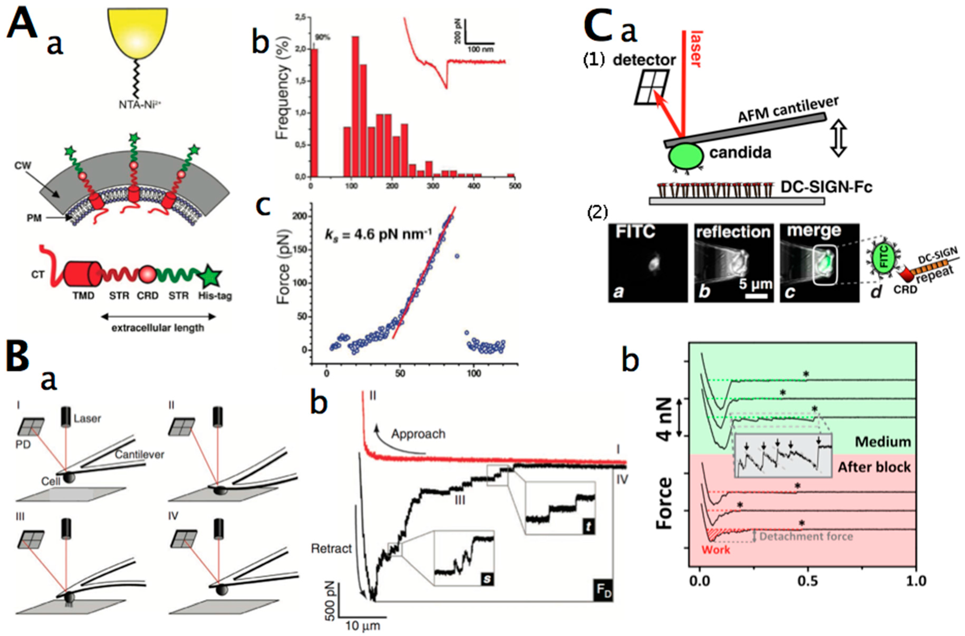
Figure 3.
(A) Nanomechanical resonators enable the measurement of mass with extraordinary sensitivity. Illustration of two mass measurement modes enabled by a fluid-filled microcantilever. (a) A suspended microchannel translates mass changes into changes in resonance frequency. Fluid continuously flows through the channel and delivers biomolecules, cells, or synthetic particles. Sub-femtogram mass resolution is attained by shrinking the wall and fluid layer thickness to the micrometre scale and by packaging the cantilever under high vacuum; (b) While bound and unbound molecules both increase the mass of the channel, species that bind to the channel wall accumulate inside the device, and, as a result, their number can greatly exceed the number of free molecules in solution. This enables specific detection by way of immobilised receptors; (c) In another measurement mode, particles flow through the cantilever without binding to the surface, and the observed signal depends on the position of particles along the channel (insets 1–3). The exact mass excess of a particle can be quantified by the peak frequency shift induced at the apex. Reprinted with permission from [141]. (B) (a) Typical setup for the detection of the nanomotion of living organisms suspended in liquid medium: (1) analysis chamber with microbial cells (green) attached to the cantilever, (2) inlet and outlet of the fluid chamber, (3) laser and photodetector; (b) (1) C. albicans deposited onto a cantilever. Courtesy of Dr. Sandor Kasas, Ecole Polytechnique Fédéral de Lausanne, Switzerland, (2) oscillations of the cantilever in nourishing medium-filled analysis chamber, (3) oscillations of the cantilever after the replacement of the growth medium with caspofungin (antifungal agent)-containing buffer. The amplitude of cantilever oscillations is in the range of 1–8 nm (unpublished data).
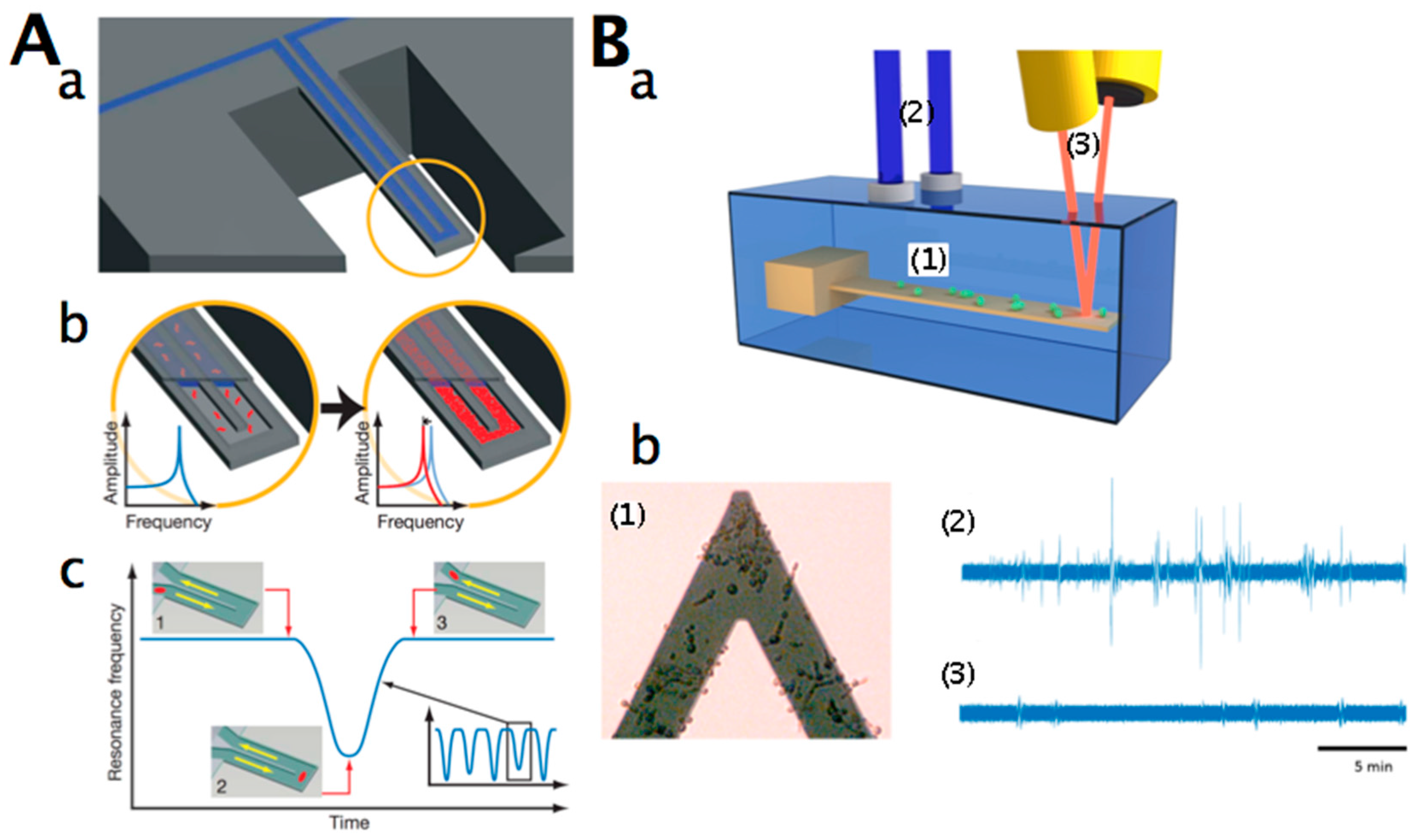
Figure 4.
(A) Cell trapping in microfluidic chambers. (a) Image of the microfluidic device; (b) Working area of microfluidic device showing (1) array of 128 imaging chambers, (2) column inlets for loading different strains, (3) eight chemical inlets controlled by independent valves, (4) outlet ports, (5) fluidic multiplexer to deliver reagents to specified rows, (6) integrated peristaltic pump for on-chip formulation of stock reagents. Reprinted with permission from [162]. (B) (a) Spotted cell microarrays using contact cell printing. Cell chips are constructed using slotted steel pins to print cells robotically from multi-well plates onto glass slides; (b) Wide-field light scattering image of a cell microarray containing around 4800 viable haploid yeast deletion strains. From ref. [159]. (C) Single-yeast cell microwell array in a microfluidic chip. (a) An overview of the cell chip. The cell chip has one simple straight microfluidic channel and two punched reservoirs; (b) Representative microscopic images for 0, 30, 60, 90, and 120 min time points in the case of α-factor treatment (DIC: bright field, yEGFP: green fluorescent, and Tdimer2: red fluorescent images). The merged and stitched images show diverse colours from a mixture of green and red fluorescence; (c) Typical time-course measurements of mating responses of individual cells. The inset shows the normalised time-course average of yEGFP fluorescence intensity. Reprinted with permission from [165]. (D) A microfluidics platform that facilitates simultaneous lifespan and gene expression measurements of aging yeast cells. Schematics of the experimental setup (upper panel). The growth of a single cell that is trapped in a replicator as a function of time is shown (lower panel). From ref. [171].
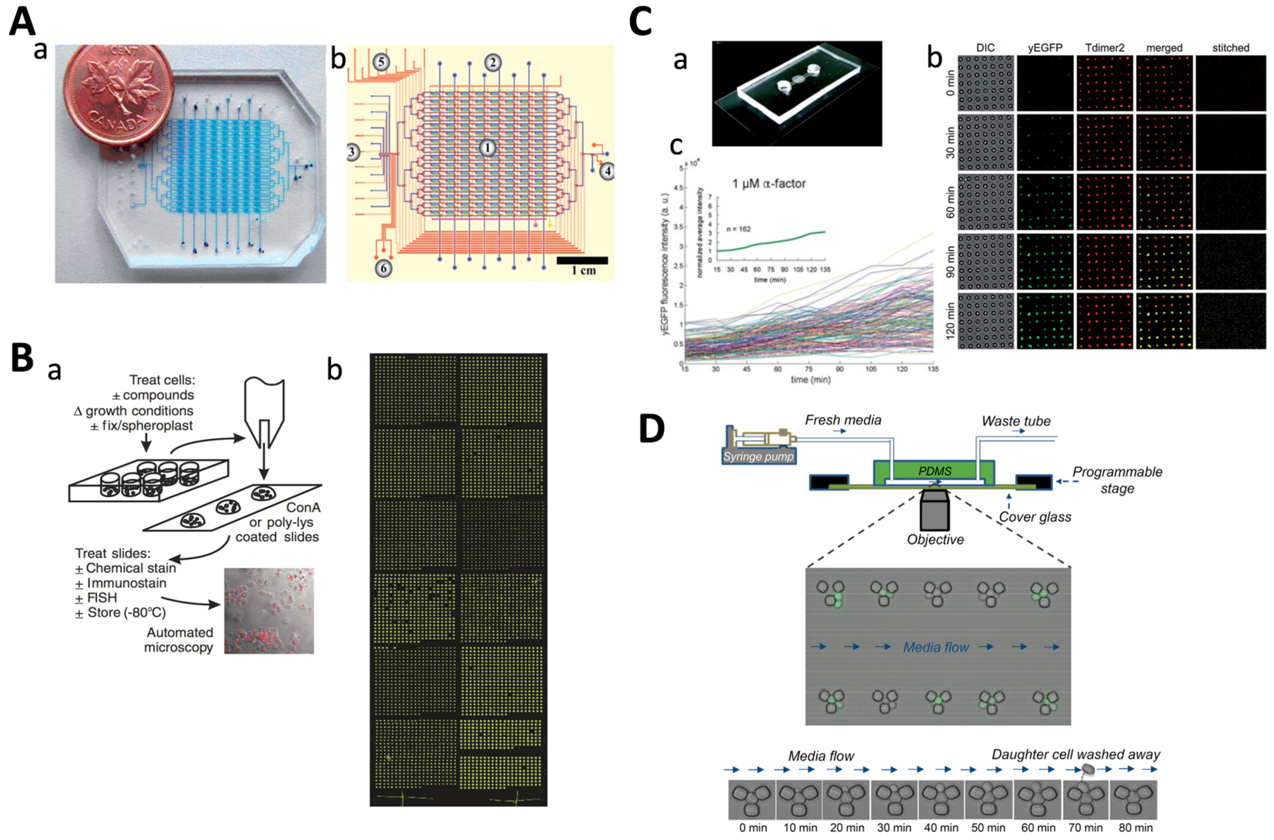
Figure 5.
(A) (a) Schematic of the microfluidic device for subjecting single cells to environmental changes. The cells are collected in the flow of cells from the lower channel using optical tweezers and positioned within the measurement region. By changing the relative flow rates at the inlets (from FC1 to FC2 and back), the environment around the cells can be changed reversibly; (b) Images showing yeast cells expressing Msn2-GFP: (1) to (4) show the cellular response (i.e., the shuttling of Msn2-GFP proteins in and out of the nucleus) when four cycles of changing the medium back and forth between 4% and 0% glucose was performed in the microfluidic chip. Reprinted with permission from ref. [239]. (B) (a) Schematic description of the microfluidic chip; and (b) the fluidic circuit; (c) Transmission micrograph of more than 200 optically trapped yeast cells; scale bar: 30 µm. Reprinted with permission from ref. [236]. (C) Optically trapped single S. cerevisiae cell. All four images are of the same cell. (a,b) show the pH distribution at t = 0 min (30 °C) and t = 12 min (70 °C); (c,d) are propidium iodide images at t = 0 min (30 °C) and t = 12 min (70 °C). The colour bar represents pH values. Reprinted with permission from ref. [231]. (D) Typical optical tweezer setup. The trapping laser light is guided onto the spatial light modulator (SLM) via a beam expander (BM1). The laser beam with the imposed phase pattern then passes a second beam expander (BM2) to be imaged onto the back focal plane of the microscope objective (MO). The schematic figure of the setup also shows the lab-on-a-chip (LOC), a fluorescent excitation light source, a filter cube (FC), a dichroic mirror (DM1), a motorised microscope stage, and a condenser lamp. The inset image shows holographically-trapped S. cerevisiae cells that were stressed with sorbitol to induce localisation of Hog1-GFP to the cell nuclei. Reprinted with permission from ref. [221].
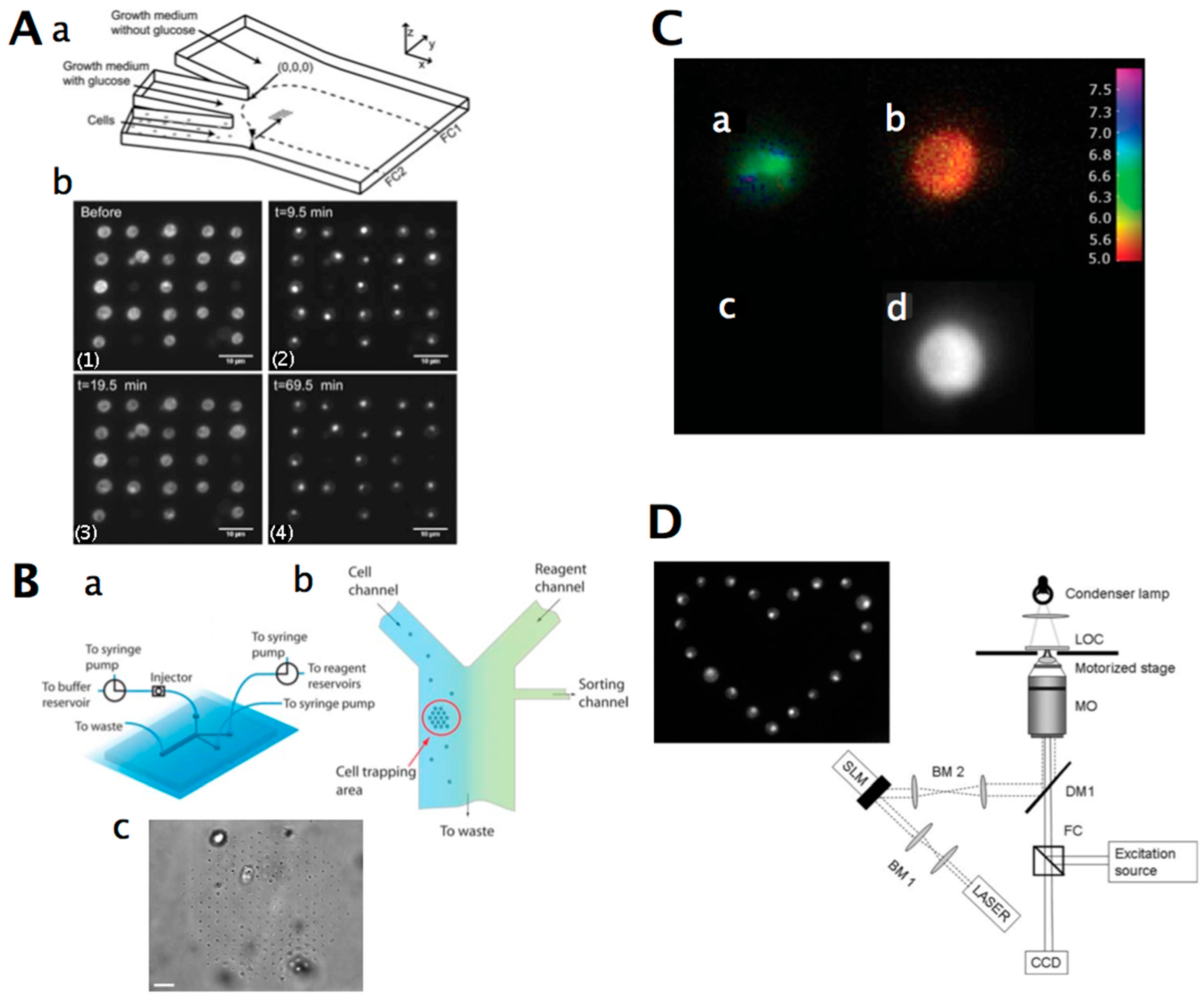
Figure 6.
(A) (a) Schematic of a dielectrophoresis (DEP) sorter with buffer and particle flows being properly balanced; (b) Trajectory of a dead yeast cell experiencing negative DEP at the constriction (left panel); living yeast cells trapped under positive DEP (right panel). Reprinted with permission from ref. [282]. (B) (a) Three-dimensional schematic of the localised motion of patterned cell clusters under the influence of dielectrophoresis. Cells can exhibit rotational and vibrational movements according to their location within the cluster. Cells located at the free ends of pearl chains have the highest occurrence of rotation, which are indicated as blue cells. Alternatively, the cells packed along the long chains bridged between the microelectrodes have the highest occurrence of vibration. The arrows indicate the direction and strength of the vibrational movement of the cells; (b) Response of BSA-treated yeast cell clusters patterned onto a finger-shaped microelectrode array when operated with a 5 Vpk−pk AC sinusoid signal. (1-i, 2-i, 3-i) Response of BSA-treated cell clusters at 5, 20, and 40 MHz, respectively. (1-ii, 2-ii, 3-ii) Schematic representation of the response of patterned cell clusters at different frequencies, with BSA-treated cells (green) being compared to untreated cells (blue). The BSA-treated cells exhibit a positive DEP response, as the distance between the two adjacent cells increases at high frequencies. Alternatively, the untreated cells exhibit a negative DEP response at frequencies higher than 30 MHz. Reprinted with permission from ref. [286]. Copyright (2015) American Chemical Society. (C) (a) Time sequence of the DEP manipulation of yeast cells. Pixels are energised in sequence to move first one cell alone and then all three together; (b) Time sequence of yeast and rat alveolar macrophages manipulated with DEP. Pixels on the chip were energised to independently move the two cells and then bring them together; (c) Complex pattern of thousands of yeast cells patterned by DEP. Pixels across the array were energised to spell out “Lab on a Chip”, attracting cells toward the local maxima of the electric field. Reprinted with permission from ref. [287].
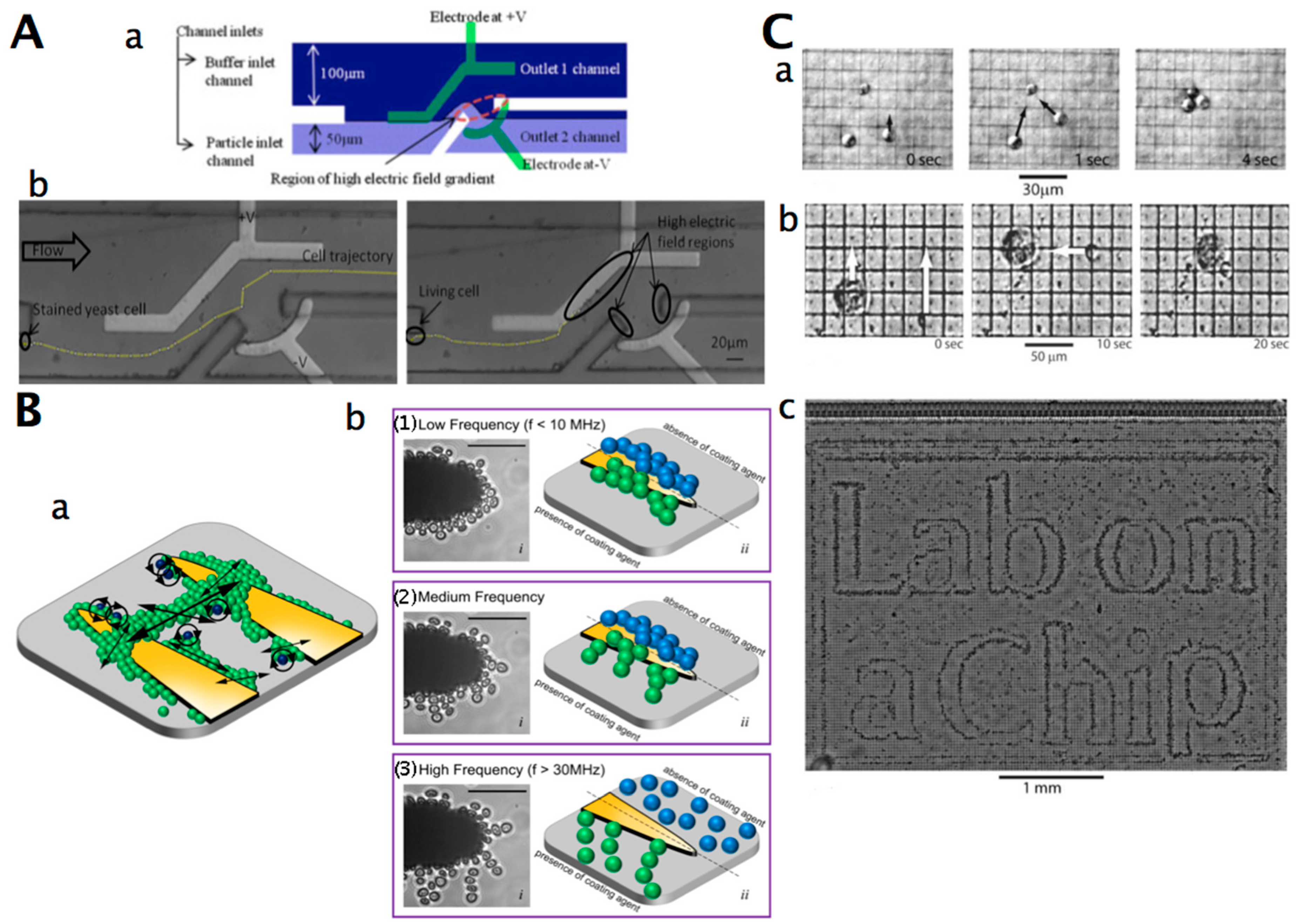

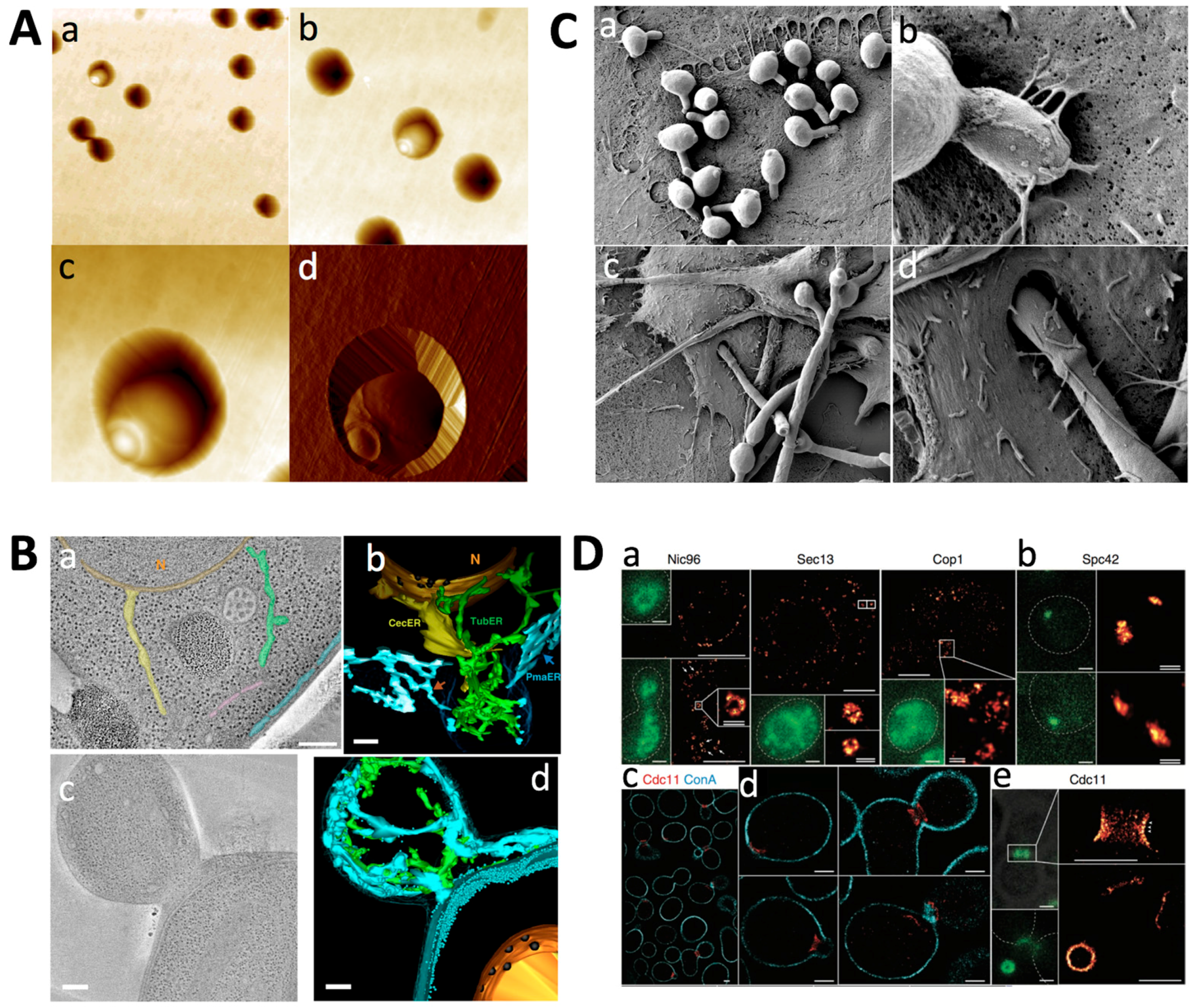
| Yeast Type | AFM Analysis | Objective | Refs |
|---|---|---|---|
| C. albicans | Imaging, cell surface elasticity | Effect of antifungal caspofungin | [16] |
| Imaging, cell elasticity | Imaging mode evaluation | [17] | |
| Imaging, force spectroscopy using concanavalin A-functionalised tips | Mapping of adhesive properties | [18] | |
| Candida parapsilosis | Imaging, adhesion force | Surface morphological characterisation | [19] |
| S. cerevisiae | Imaging | Immobilisation method | [8] |
| Imaging | Immobilisation method | [9] | |
| Imaging, force spectroscopy using concanavalin A-functionalised tips | Mapping cell wall polysaccharides | [20] | |
| Imaging, cell elasticity | Mapping of cell elasticity | [21] | |
| Imaging | Cell surface change on thermal and osmotic stress | [22] | |
| Imaging, motion analysis | Nanomechanical motion analysis | [23] | |
| Imaging | Effect of electromagnetic field and antifungal nystatin on the cell wall | [24] | |
| Imaging, cell elasticity | Immobilisation method | [10] | |
| Imaging | Immobilisation method | [11] | |
| Imaging, cell surface elasticity | Effect of antifungal caspofungin | [16] | |
| Sc. pombe | Imaging | Cell surface change on thermal and osmotic stress | [22] |
Table 2.
Super-resolution optical microscopy techniques (adapted from [37]).
| Technique | Description | Spatial Resolution | Timescale |
|---|---|---|---|
| Fluorescence imaging with one-nanometer accuracy (FIONA) | Localises and tracks single-molecule emitters by finding the centre of their diffraction-limited point-spread function (PSF). | ~1.5 nm | ~0.3 ms |
| Single-molecule high-resolution colocalisation (SHREC) | Two-colour version of FIONA. Two fluorescent probes with different spectra are imaged separately and then localised and mapped onto the plane of the microscope. | <10 nm | ~1 s per frame |
| Single-molecule high-resolution imaging with photobleaching (SHRImP) | Uses the strategy wherein, upon photobleaching of two or more closely-spaced identical fluorophores, their position is sequentially determined by FIONA, starting from the last bleached fluorophore. | ~5 nm | ~0.5 s per frame |
| Nanometer-localised multiple single-molecules (NALMS) | Uses a similar principle to single-molecule high-resolution imaging with photobleaching to measure distances between identical fluorescent probes that overlap within a diffraction-limited spot. | ~8 nm | ~1 s per frame |
| Photoactivatable localization microscopy (PALM) | Serially photoactivates and photodeactivates many sparse subsets of photoactivatable fluorophores to produce a sequence of images that are combined into a super-resolution composite. | ~2 nm | ~1 min |
| PALM with independently running acquisition (PALMIRA) | Records non-triggered spontaneous off–on–off cycles of photoswitchable fluorophores without synchronising the detector to reach faster acquisition. | ~50 nm | ~2.5 min |
| Single particle tracking PALM | Combines PALM with live-cell single fluorescent particle tracking. | ||
| Stimulated emission depletion (STED) | Reduces the excitation volume below that dictated by the diffraction limit by coaligning one beam of light capable of fluorophore excitation with another that induces de-excitation by stimulated emission. | ~16 nm | ~10 min |
| Stochastic optical reconstruction microscopy (STORM) | Small sub-populations of photoswitchable fluorophores are turned on and off using light of different colours, permitting the localisation of single molecules. Repeated activation cycles produce a composite image of the entire sample. | <20 nm | ~mins |
Table 3.
Examples of yeast molecule interaction studies using single-molecule force spectroscopy (SMFS).
| Cell Type | Interacting Molecule 1 | Interacting Molecule 2 | Rupture Force (pN) | Refs |
|---|---|---|---|---|
| C. albicans | Als5p | Fibronectin | 2800 ± 600 | [103] |
| S. cerevisiae | Prion protein Sup35 hexapeptide | Prion protein Sup35 hexapeptide | — | [104] |
| Prion protein Sup35 hexapeptide antiparallel hairpin structure | Prion protein Sup35 hexapeptide antiparallel hairpin structure | 32–134 | [105] | |
| Nucleoporin | Nucleoporin | — | [106] | |
| Nucleoporin | Importin | — | ||
| Flo1p | Flo1p | 300 (100–600) | [107] |
Table 4.
Examples of yeast receptor–ligand interaction studies using single-molecule force spectroscopy (SMFS) on cell surfaces.
| Cell Type | Cell Receptor | Ligand | Rupture Force (pN) | Refs |
|---|---|---|---|---|
| C. albicans | Cell surface β-mannan | Anti-β-1,2-mannoside antibodies | 41 ± 14 | [108] |
| Cell surface β-glucans | Anti-β-1,3-glucan antibodies | 38 ± 10 | [108] | |
| Cell wall chitin | WGA 1 lectin | 65 ± 19 | [108] | |
| Cell wall | Streptococcus mutans exoenzyme glycosyltransferase B | 1000–2000 | [109] | |
| C. glabrata | Epa6p | Hydrophobic surface | - | [110] |
| Cell surface β-mannan | Anti-β-1,2-mannoside antibodies | 54 ± 9 | [108] | |
| Cell surface β-glucans | Anti-β-1,3-glucan antibodies | 41 ± 8 | [108] | |
| Cell wall chitin | WGA 1 lectin | 41 ± 8 | [108] | |
| S. cerevisiae | Cell surface α-mannan | Con A 2 lectin | 75-200 | [111] |
| Cell surface α-mannan | Con A 2 lectin | 92 ± 35 | [108] | |
| Cell surface β-glucans | Anti-β-1,3-glucan antibodies | 42 ± 7 | [108] | |
| Cell wall chitin | WGA 1 lectin | 54 ± 19 | [108] | |
| Wsc1p-His-tagged | NTA-Ni2+ | - | [112,113,114] | |
| HA 3-tagged Ccw12p | Anti-HA antibody | 69.3 ± 31.4 | [115] | |
| Ste2p | α-factor | 250 | [116] | |
| S. pastorianus | Flo protein | Glucose | 121 ± 53 | [111] |
| Flo protein | Con A 2 | 117 ± 41 | [111] |
1 WGA: wheat germ agglutinin; 2 Con A: concanavalin A; 3 HA: human influenza hemagglutinin.
| Cell Type | Interaction Partner | Variables | Refs |
|---|---|---|---|
| C. albicans | Staphylococcus aureus | Deletion of ALS3 (adhesion gene) | [123] |
| Hydrophobic DDP 1 coated surface | Surface hydrophilicity, hydrophobicity, deletion of HGC1, compared to S. cerevisiae | [124] | |
| C. albicans hyphae | Deletion of ALS3 and ALS1 (adhesion genes) | [125] | |
| DC-SIGN 2 | Differences in the N-mannan structure of the cell wall | [118] | |
| C. glabrata | Adhesin Epa6p | Surface hydrophilicity, hydrophobicity, expressed and deleted EPA6 | [110] |
| S. cerevisiae | Abiotic surface | Surface hydrophilicity, hydrophobicity BSA coating, life cycle stage, glutaraldehyde-treated cells | [126] |
| Silica surface | Different silica with defined roughness | [127] | |
| Methacrylate polymers surface | Polymer imprinted and non-imprinted surface | [128] | |
| Bare and polydopamine-coated glass | Polydopamine coating | [129] |
1 DDP: dodecyl phosphate; 2 DC-SIGN: dendritic cell-specific intercellular cell adhesion molecule-3 (ICAM-3)-grabbing non-integrin.
| Yeast Type | Cell Patterning Method | Issue Addressed | Refs |
|---|---|---|---|
| S. cerevisiae | Patterning on adhesive micropatterns | Microcontact printing of concanavalin A | [157] |
| Mechanical cell patterning in microfluidic microchambers | Monitoring dynamics of single-cell gene expression | [158] | |
| Robotic cell printing | Systematic profiling of cellular phenotypes | [159] | |
| Mechanical cell patterning using trap barriers | Single cell gene expression analysis | [160] | |
| Robotic cell printing | Localisation of the yeast proteome during polarised growth | [161] | |
| Mechanical cell patterning in microfluidic microchambers | Quantitative analysis of the yeast pheromone signalling response | [162] | |
| Patterning on adhesive micropatterns | Microcontact printing of biotinylated bovine serum albumin | [163] | |
| Mechanical cell patterning using trap barriers | Whole lifespan microscopic observation | [164] | |
| Mechanical cell patterning in microfluidic single-cell microwells | Real-time cellular responses of the mating MAPK pathway | [165] | |
| Mechanical and chemical patterning in microchambers | Molecular phenotyping of aging in single cells | [166] | |
| Mechanical cell patterning using trap barriers | Single cell analysis of yeast replicative aging | [167] | |
| Mechanical cell patterning in elongated cavities | Monitoring the dynamics of cell division | [168] | |
| Mechanical cell patterning using trap barriers | Studying ageing and dynamic single-cell responses | [169] | |
| Patterning in microcavity array by negative pressure, and embedded in agarose gel layer | Long-term single cell growth observation | [170] | |
| Mechanical cell patterning using trap barriers | Automated measurements of single-cell aging | [171] | |
| Mechanical cell patterning using trap barriers | High-throughput analysis of yeast replicative aging | [172] | |
| Sc. pombe | Mechanical patterning in culture microchambers | Mechanical mechanisms redirecting cell polarity and cell shape in fission yeast | [173] |
| Mechanical patterning in single-cell microwells | Determination of the mechanical forces involved in cell growth | [174] | |
| Mechanical patterning in microchambers | Time-lapse fluorescence observation of the effect of a microtubule-inhibiting drug | [175] | |
| Mechanical trapping in single-cell cavities | Fission yeast synchronisation | [176] | |
| Mechanical barrier single-cell trapping | Lon-term observation using super-resolution fluorescence microscopy | [177] | |
| Mechanical patterning in chemostat microchambers | Long-term single-cell analysis | [178] | |
| Mechanical patterning in culture microchambers | Studies of cellular aging | [179] |
MAPK: Mitogen-activated protein kinases.
| Yeast Type | Issue Addressed | Refs |
|---|---|---|
| C. albicans | Control and manipulation of pathogenic yeast for live cell imaging and interaction with host cells | [237,238] |
| Hanseniaspora uvarum and S. cerevisiae | Confinement of an individual H. uvarum cell by S. cerevisiae cells increases the average generation time | [240] |
| S. bayanus | Study of growth pattern of cells under line optical tweezers generated by time-shared multiple optical traps | [241] |
| S. cerevisiae | On-chip single-cell separation and immobilisation using optical manipulation and thermosensitive hydrogel | [229] |
| Real-time detection of hyperosmotic stress response in optically trapped single yeast cells using Raman microspectroscopy | [230] | |
| Optical manipulation of cells to microscopically observe environmentally-induced size modulations and spatial localisation of GFP-tagged proteins to elucidate various signalling pathways | [232] | |
| Optical trapping and surgery of living cells using two operational modes of a single laser | [242] | |
| Selection and positioning of single cells combined with microscopy analysis in a microfluidic channel; cycling of GFP-tagged Mig1p and Msn1p between the cytosol and nucleus | [239] | |
| Optical trapping and fluorescence microscopy investigation of the internal pH response and membrane integrity with increasing temperature | [232] | |
| Automated transportation of single cells | [243] | |
| Development of a microfluidic array cytometer based on refractive optical tweezers for parallel trapping, imaging, and sorting of individual cells | [236] | |
| Microfluidic sorting of arbitrary cells with dynamic optical tweezers | [235] | |
| Development of graded-index optical fibre tweezers with long manipulation length | [244] | |
| Position yeast cells in a microfluidic chamber to study glycolytic oscillations | [245,246] | |
| Tomographic phase microscopy with live cell rotation using holographic optical tweezers | [247] | |
| Development of a photonic crystal optical tweezer to trap an array of yeast cells | [248] | |
| Sc. pombe | Displacement of the lipid granules | [249] |
| Displacement of the nucleus | [250,251] | |
| Laser ablation of microtubules in vivo | [226] | |
| In vivo anomalous diffusion and weak ergodicity breaking of lipid granules | [252] | |
| Quantitative determination of optical trapping strength and viscoelastic moduli inside living cells | [253] |
| Yeast Type | Manipulation Method | Issue Addressed | Refs |
|---|---|---|---|
| S. cerevisiae | Electrophoresis and electroosmosis | Cell transport in microfluidic channels | [272] |
| Dielectrophoresis | Live and dead cell separation | [278] | |
| Magnetic patterning | Demonstration of magnetic micromanipulation of magnetically labelled cells | [276] | |
| Electroosmosis | Cell transport via electromigration in polymer-based microfluidic devices | [288] | |
| Dielectrophoresis (AC DEP) | Sorting live and dead cells | [280] | |
| Dielectrophoresis (AC DEP) | DEP tweezer for single cell manipulation | [267] | |
| Dielectrophoresis | Multiple frequency DEP separation and trapping of live and dead cells | [281] | |
| Diamagnetic trapping | Cell magnetic trapping in an array using a CoPt micromagnet array | [289] | |
| Magnetophoresis | Contactless diamagnetic trapping of cells onto a micromaget array | [289] | |
| Electrophoresis | Electrophoretic cell manipulation in a microfluidic device | [290] | |
| Dielectrophoresis (AC DEP) | Separation of yeast cells from blood cells in a microfluidic chip | [268] | |
| Dielectrophoresis | Live and dead cell separation | [279] | |
| Dielectrophoresis | Microfluidic chip for guiding cells by AC electrothermal effect and capturing by nDEP trap | [277] | |
| Dielectrophoresis (DC DEP) | Separation of a mixture of S. cerevisiae and Escherichia coli cells | [291] | |
| Dielectrophoresis (AC/DC DEP) | Sorting live and dead cells | [282] | |
| Dielectrophoresis, electroosmosis, electrophoresis | High-throughput trapping of cells, separation of live and dead cells | [271] | |
| Dielectrophoresis | Cell manipulation and immobilisation using photo-crosslinkable resin inside microfluidic devices | [292] | |
| Dielectrophoresis | Controlled rotation and vibration of cell clusters | [286] | |
| Magnetic manipulation | Magnetic manipulation of Fe3O4-doped hydrogel-coated cells | [293] |
Table 9.
Comparison of high-resolution techniques for imaging yeast cells (adapted from [303]).
| Characteristic | AFM | Electron Microscopy (SEM, TEM) | Super-Resolution Fluorescence Microscopy (PALM, STORM, SIM) |
|---|---|---|---|
| Resolution | ~10 nm 1 | ~1–10 nm | ~5–50 nm |
| Live cell | Yes | No | Yes |
| Sample preparation requirement | Little | Little to substantial | Little to moderate |
| Sample preparation time | 10 min–1 d | 2 h–5 d | 30 min |
| Image acquisition time | ~5 min | 5–10 min | Up to 24 h |
| Equipment cost | €150,000–350,000 | €500,000 | €250,000–500,000 |
| Operational costs | Low | High | Moderate |
| Advantages | Localisation (and force spectroscopy) of single proteins; observation of dynamic processes; various environments (temperature, liquid, air, etc.) | Imaging of the cell ultrastructure at very high resolution | Time resolution. |
| Disadvantages | Only the cell surface is analysed; only one single cell at a time; slow temporal resolution; various sources of artifacts, such as cell or tip alteration | Fixation artifacts; no dynamics; no information on physical properties of proteins | Labelling is required |
1 Depends on the flatness of the surface; the provided value refers to the resolution for observing cells.
| Characteristic | Optical Tweezers | Magnetic Tweezers | AFM | Micropipette |
|---|---|---|---|---|
| Type | Point | Global/point | Point | Point |
| Non-contact | Non-contact | Contact | Contact | |
| Spatial resolution (nm) | 0.1–2 | 5–10 | 0.5–1 | - |
| Temporal resolution (s) | 10−4 | 10−1–10−2 | 10−3 | - |
| Stiffness (pN nm−1) | 0.005–1 | 10−3–10−6 | 10–105 | 0.01–1000 |
| Force range (pN) | 0.1–100 | 10−3–102 | 10–104 | 1–1000 |
| Probe size (µm) | 0.25–5 | 0.5–5 | 100–250 | |
| Energy dissipation | Yes | No | No | No |
| Surface considerations | No | No | Yes | Yes |
| Features | Low noise and drift dumbbell geometry; access inside a cell | Force clamp, bead rotation, specific interactions; access inside a cell | High-resolution imaging | Controlled deposition/transfer of selected cells |
| Limitations | Photodamage, sample heating, non specific | No manipulation (force hysteresis) | Large high-stiffness probe, large minimal force, non specific | Low throughput |
© 2016 by the authors; licensee MDPI, Basel, Switzerland. This article is an open access article distributed under the terms and conditions of the Creative Commons Attribution (CC-BY) license (http://creativecommons.org/licenses/by/4.0/).
Share and Cite
MDPI and ACS Style
Willaert, R.; Kasas, S.; Devreese, B.; Dietler, G. Yeast Nanobiotechnology. Fermentation 2016, 2, 18. https://doi.org/10.3390/fermentation2040018
AMA Style
Willaert R, Kasas S, Devreese B, Dietler G. Yeast Nanobiotechnology. Fermentation. 2016; 2(4):18. https://doi.org/10.3390/fermentation2040018
Chicago/Turabian StyleWillaert, Ronnie, Sandor Kasas, Bart Devreese, and Giovanni Dietler. 2016. "Yeast Nanobiotechnology" Fermentation 2, no. 4: 18. https://doi.org/10.3390/fermentation2040018
Note that from the first issue of 2016, this journal uses article numbers instead of page numbers. See further details here.