
Strain Engineering of the CeNi5 System


School of Science and Technology, Nottingham Trent University, Nottingham NG11 8NS, UK
Magnetochemistry 2016, 2(4), 39; https://doi.org/10.3390/magnetochemistry2040039
Submission received: 16 August 2016
/
Revised: 27 September 2016
/
Accepted: 19 October 2016
/
Published: 1 November 2016
Abstract
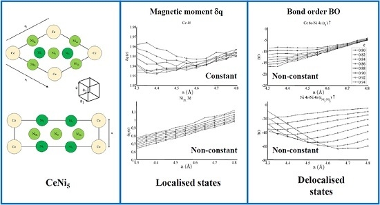
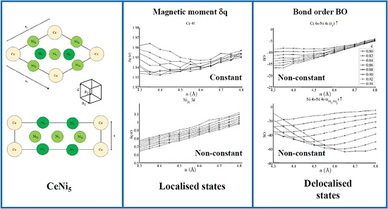
:The effect of strain on the CeNi5 system has been investigated using density functional theory (DFT). The studies have shown that localised Ce 4f and Ni 3d states carry the magnetic moment of the material. The Ce 4f moment remains relatively unchanged during strain whereas the Ni 3d moment increases as the strain becomes increasingly tensile in both the basal and non-basal directions. A significant strain-dependent interaction exists between delocalised, non-magnetic Ce 6s–Ni 4s states. A weaker group of Ni 3d–Ce 6s/Ni 4s and Ni 3d–Ni 3d interactions exist, indicating that competing localised and delocalised mechanisms act on the Ni 3d states during strain.
1. Introduction
Intermetallic compounds have attracted considerable interest because of both their technological versatility and the range of fundamental phenomena that they exhibit. RNi5 materials—where R is a Y, La, or a rare earth element—are used extensively in Ni–M–H energy storage units, reflecting the wider interest in the use of intermetallic materials in this technology [1].
CeNi5 has a CaCu5-type structure with a lattice parameter a = 4.87 Å and a ratio of non-basal to basal dimension of 0.83 [2]. The structure has space group P6/mmm. Investigations of CeNi5 [3,4] have shown that the local Ce and Ni spin densities are separable, but recent studies into the pressure dependence of the system [5] have highlighted the limitations of a simplistic Stoner model of the magnetic susceptibility of the system. The same study [5] also demonstrated for the contemporary YNi5 system that a complex set of interactions exists between the spin and orbital moment. It has also been shown that CeNi5 demonstrates spin fluctuations [6,7,8], which themselves are an interpolative model [9] that bridges the weakly and strongly ferromagnetic limits.
The magnetic description of CeNi5 is consequently complex and the current work aims to elucidate the interactions within the bulk crystal by systematically deforming the crystal looking at its response. This technique is conceptually similar to the strain engineering, which has been an important component of semiconductor physics for a number of years [10]. The technique has proven successes, and extensive studies exist of Si, Ge, and III-V alloy systems [11,12]. In addition, recent studies have investigated wide-bandgap materials such as SiC [13]. These studies have a considerably developed understanding of the electronic nature of the materials. Studies of strain across intermetallic materials have shown a greater focus towards their mechanical behaviour and are predominantly applied investigations. Unprecedented studies in surface science [14], however, have used the technique to identify phase transitions in the H/Pt(111) system. The studies have shown that only a nominal change in the Pt(111) surface lattice parameter can cause a shift in the binding position of the surface hydrogen and have demonstrated the utility of strain in fundamental investigations of non-semiconducting systems. The application of [14] is of key importance for the energy industry, as strained Pt overlayers formed across a Pt3Ni substrate are significantly more catalytically active in the oxygen reduction reaction (ORR)—a key step in energy storage technology—than their unstrained counterparts [15]. This observation is particularly germane in the current studies: The importance of intermetallic compounds in energy storage has already been identified, and a systematic knowledge of their behaviour under strain may suggest optimal engineering strategies for these materials.
The current work is laid out in the following way: The theoretical techniques are outlined, and a discussion of the results obtained from these techniques is then presented. The results focus on the real space models of the CeNi5 system and will discuss the spin density, the density of states, and the crystal orbital overlap population (COOP) of the electronic states within the bulk system. The work will then conclude with a summary of the key findings.
2. Theory
The SIESTA LCAO-DFT package [16] was used to perform the simulations presented in this paper. The exchange–correlation interaction was estimated using the revised PBE functional [17]. The atomic orbitals were described using double zeta orbital basis sets [18] and were composed of Ni 3d and 4s orbitals with Ni 4p polarization states, and Ce 4f and 6s orbitals with Ce 6p polarization states. Relativistic pseudopotentials for Ni and Ce were generated using valence configurations of 4s24p03d84f0 and 6s26p05d14f1, respectively, and using the improved Troullier–Martins method [19,20]. A single Kleinman–Bylander projector was used to represent each angular momentum channel [21]. Brillouin zone integration was performed using an optimal mesh with a fineness of 25 Å [22], and a plane-wave cut-off energy of 300 Ry was used. The GGA method was employed without Hubbard correction because of the Stoner-like character of the system [23]. All calculations presented in this paper were fully spin-polarized. A linear mixing strategy was used to combine the working density matrices during the self-consistency stage of the calculation. A low mixing weight (<1%) was using during this part of the calculation in a strategy that has been proven to reliably generate the ground magnetic state in recent studies of Ce/Pd surface alloys [24].
Figure 1 shows the CeNi5 unit cell used throughout the current work. The dimensions of the unit cell are defined by the diagonal length parameter a where
The non-basal dimension is defined by c. Throughout this paper, c is presented in units of a; using this definition, the product ca is in units of Å. During each simulation, the a and c were held constant, and the self-consistent field for that particular system was determined. The ion cores were kept fixed at their P6/mmm sites for every simulation, and no relaxation of the ion core position was performed.
The spin populations were determined using
The and were, respectively, the spin-up and spin-down components of the atomic charge. All results presented in the current work were from a Mulliken population analysis; estimations of the same parameters using both the Hirshfeld [25,26] and Voronoi [26,27] populations were not significantly different to the Mulliken analysis and are consequently not presented. In the current work, the bond orders (BO) were defined as the integral of the crystal orbital hamiltonian population (COHP) [28] up to the Fermi energy EF [29]. The COHP is closely related to the crystal orbital overlap population (COOP), but the COHP is a partition of the systems band structure energy rather than the electrons. The BO presented in this work should be interpreted as a measure of the relative interaction strength rather than as a direct measure of the amount of electron sharing between orbitals.
Using this formulation, the bond order (BO) can be interpreted as the RKKY interaction [24] using
where kF is the Fermi wave-vector, r is the inter-nuclear distance, and J is the interaction strength between spins. The inter-nuclear distances are defined by parameter a in Equation (1) and took values of 4.3–4.8 Å. Based on this length range, the term predicts a ferromagnetic interaction between the Ni and Ce states, which is seen in the following section.
3. Results and Discussion
Figure 2 shows the equations of state obtained for the bulk CeNi5 system. The system has been strained by ±5% of the equilibrium lattice parameter; within this range, the Kohn–Sham energies EKS are seen to change by 200–300 meV. Pedagogically, the strain is therefore adequate to evidence changes in the dipole moment, densities of states, and bond order, which will be the focus of the remainder of this work. However, this range of strain would also be accessible experimentally by either changing the stoichiometry of the unit cell by depositing the sample on a support with a different lattice constant—and then particularly studying the interface region between the CeNi5 and the support—or by applying mechanical strain. Additionally, an applied pressure of up to 7.17 GPa can be used to effect a 5% change in the lattice parameter [30].
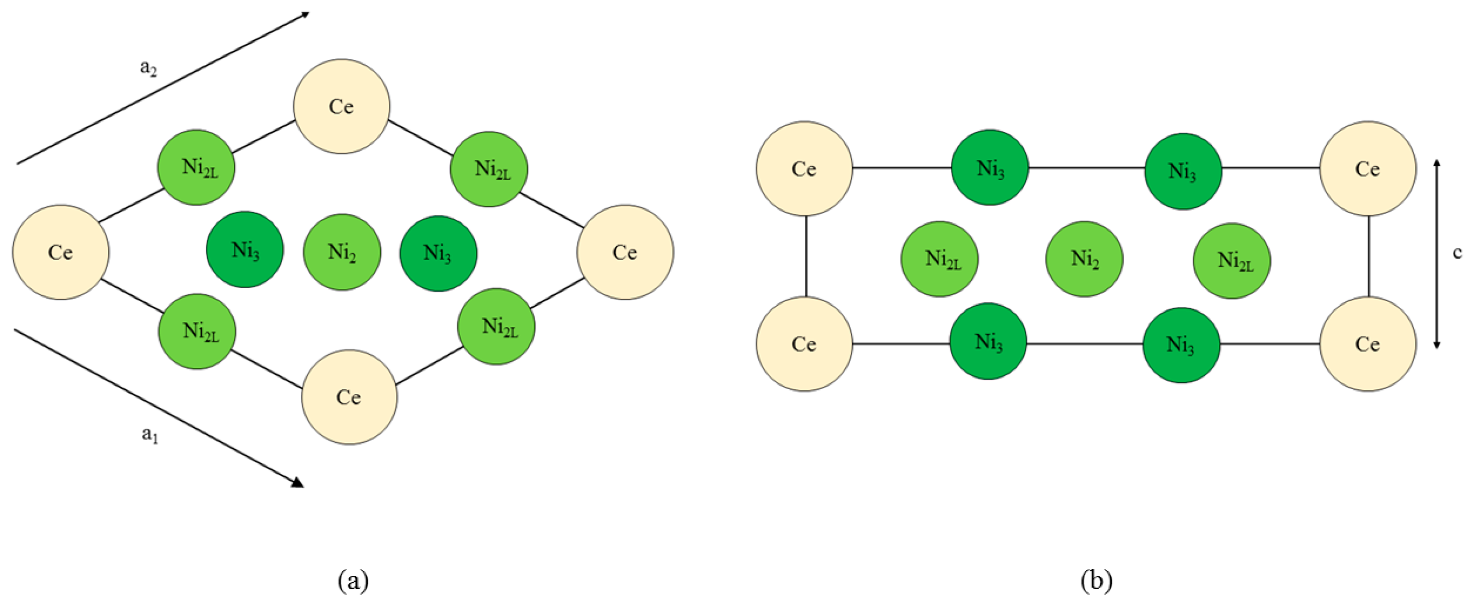
Figure 3 shows the spin populations of the (a) Ce 6s, (b) Ce 4f, (c–e) Ni 4s, and (f–h) Ni 3d states evaluated across the range of strains defined in Figure 2. The results are shown for each of the different types of Ni species present in the unit cell—that is, Ni3, Ni2, and Ni2L. Because of their different binding geometries and local symmetry, the electronic character of each of these species is anticipated to be different, particularly between the twofold Ni2 and Ni2L atoms and threefold Ni3 atom. The similarities between each of these species and their response under strain will therefore be scrutinised in this work.
The delocalised Ce 6s and Ni 4s states have , which is comparatively negligible to the Ce 4f and Ni 3d states. In addition, the variation in the moment of the Ce 4f state is much smaller than that of any of the Ni 3d states. The variation in the Ce 4f moments shown in Figure 3b is approximately 0.035e. This is over an order of magnitude smaller than the variations of approximately 0.400e seen for the Ni 3d states in Figure 3d–f. The polarizability of each of the Ni 3d states is therefore much larger than that of the Ce 4f states under the influence of strain.
Figure 3d–f also shows that the rate at which changes with a—i.e., the slope of the curves shown in those figures—are generally the same for each of the Ni species, particularly for the Ni2 and Ni2L pair. Certain exceptions exist for the Ni3 case, particularly for large out-of-plane strains (c = 0.94). This is highly suggestive that the mechanism by which the Ni 3d orbitals are distorted under strain is predominantly delocalised or non-directional. The differences between the Ni2/Ni2L and Ni3 responses indicate that increasing the local valence of the Ni atom makes the local orbitals modestly more susceptible to distortion; however, Figure 3d–f show very clearly that these effects are minor when compared to those that are delocalised.
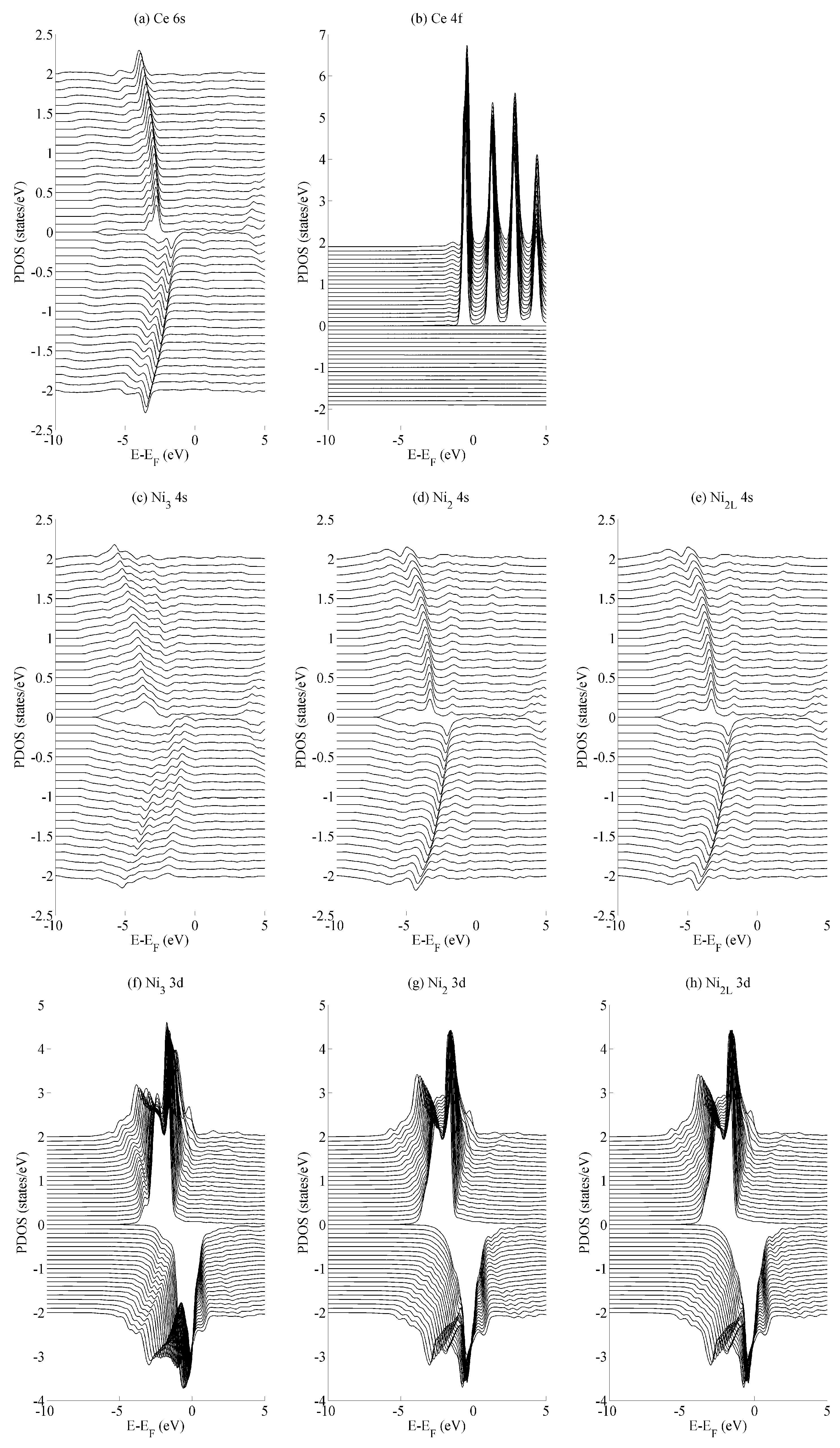
The effects of basal strain (variation in a) on the projected density of states (PDOS) is shown in Figure 4 for the (a) Ce 6s, (b) Ce 4f, (c–e) Ni 4s, and (f–h) Ni 3d states. The Ce 6s ↑ (↓) states show a maximum (minimum) at −2.8 eV (−1.7 eV) for the case of maximum compressive strain (a = 4.00 Å). These shift to lower energies, specifically at −4.0 eV (−3.5 eV) for the case of maximum tensile strain (a = 5.00 Å). The Ce 4f states in Figure 4b show significantly less variation with the only occupied spin-up state remaining comparatively constant at −0.5 eV. All spin down components of Ce 4f lie in the region . A similar level of localisation is evident for the Ni 3d states. All three species have leading spin-up (spin-down) states at approximately −1.6 eV (−0.3 eV Ni2/Ni2L and −0.03 eV Ni3). The variance in the position of the Ni 3d states is ±0.05 eV across the range of strains considered in the current work, whereas the Ni 4s states show a variance of ±1.0 eV.
The different variances in the peak position are typical for localised states—particularly the Ce 4f states and, to a very similar extent, the Ni 3d states—and their delocalised (s) contemporaries. In the delocalised case, the energetic variances compensate for changes in the overlap that occurs as the crystal is deformed. Consequently, the variances are greater for states that demonstrate a greater degree of delocalization—in this case, for the Ce 6s and Ni 4s states. Crystal field effects are also evident from the formation of additional electronic states that evolve as the amount of strain is varied. The development of these additional states are seen particularly for the Ni2/Ni2L 4s and Ni3 3d sequences shown in Figure 4c–e and Figure 4f–h, respectively. However, they are precluded from further analysis, as the focus of the paper is on the interaction between states rather than the character of individual states.
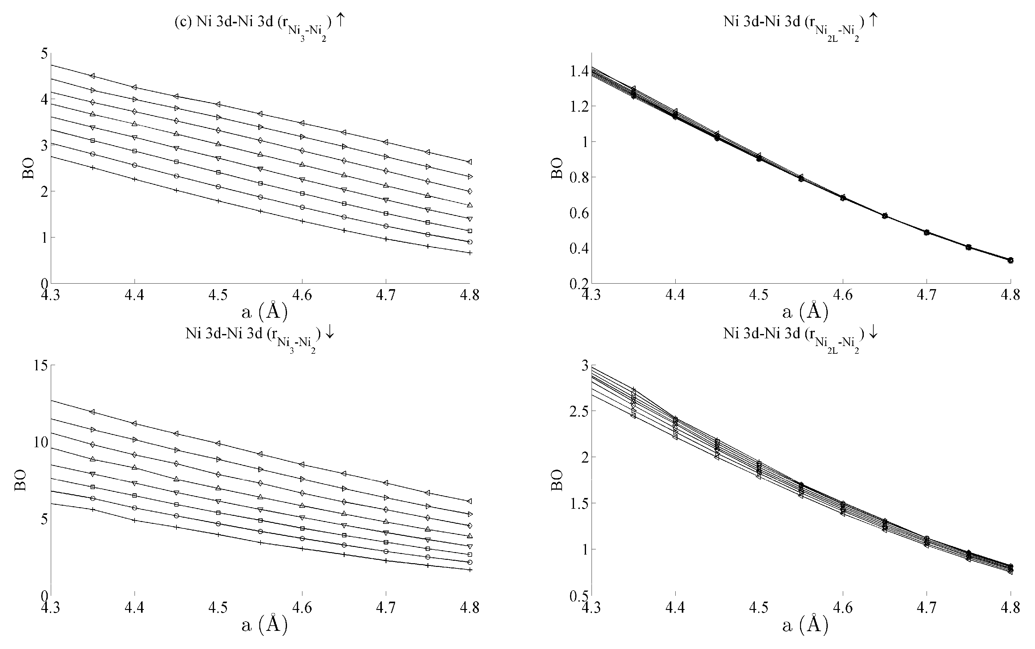
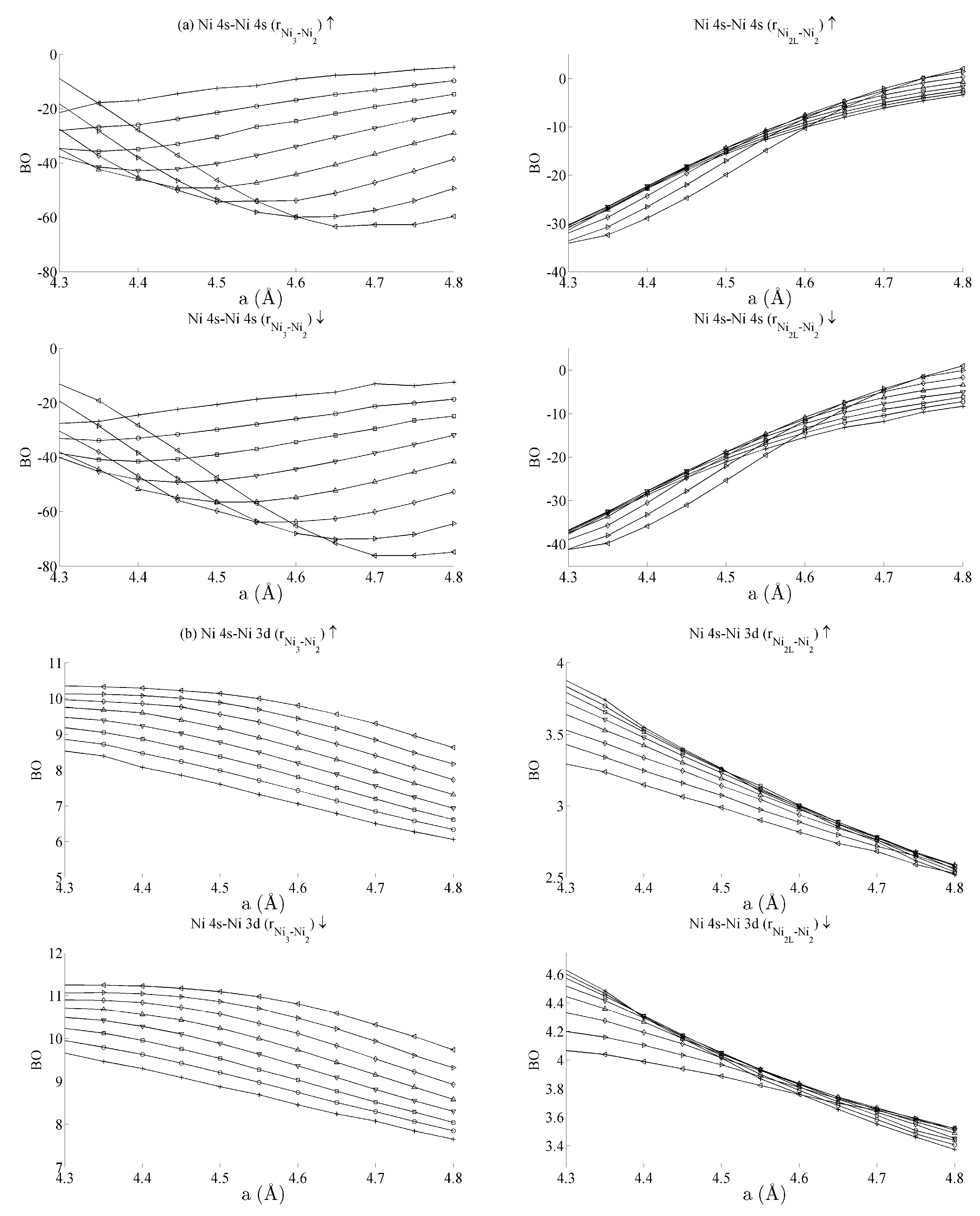
Figure 5 and Figure 6 respectively show the bond order (BO) between all groups of Ce–Ni and Ni–Ni interactions. In the current work, BO is used as a measure of interaction strength in the same way it was used in recent studies of Ce/Pd surface alloys [24]. A positive (negative) value for BO indicates that the interaction is bonding (anti-bonding). Figure 5a shows the Ce 6s–Ni 4s interactions. The Ce–Ni2 BO were not significantly different to the Ce–Ni21 BO presented and are therefore removed for brevity. Figure 5a shows that all Ce 6s–Ni 4s interactions decrease in anti-bonding character as the in-plane lattice parameter a increases. However, the out-of-plane distortion affects the two groups of interactions differently. The Ce–Ni3 interaction becomes increasingly anti-bonding as c increases, whereas the reverse is true for the Ce–Ni2L interaction. This shows that, though the Ce–Ni3 inter-nuclear direction is purely in-plane, its binding is strongly affected by out-of-plane distortion. A re-ordering is also seen between the Ni 4s–Ni 4s interactions in Figure 6a. This is clearly demonstrated for in the Ni3–Ni2 interaction; moreover, though it is also observable for Ni2L–Ni2, the effect is clearly enhanced if the inter-nuclear vector lies out of the basal plane.
Figure 5b shows the BO between the Ce 6s–Ni 3d states. The interaction is bonding but there is a smaller variation in strain than was seen for the Ce 6s–Ni 4s case. This is because the Ni 3d states are more localised. This trend continues for the Ce 4f cases in Figure 5c,d. Ce 4f states lie at higher energies than the Ni 3d states and are consequently spatially more localised. Figure 5c,d thus precisely show that the bond orders become progressively smaller as the localisation increases, particularly for the group of Ce 4f–Ni 3d.
Table 1 summarises the bond order curves presented in Figure 5. In both Table 1 and Table 2, the average bond order and the standard deviation of the bond order were calculated using the data presented in Figure 5 and Figure 6, across all strain states. Table 1 clearly shows that the largest variance of BO occurs between the delocalised Ce 6s–Ni 4s states with comparatively nominal changes being seen for all the remaining interactions. This trend is seen to a similar extent in Table 2, which analyses the Ni–Ni interactions presented in Figure 6a–c in the same way. In the latter case, however, stronger interactions are seen between the Ni 3d states and the other Ni states than are seen between Ce 4f and the remaining states.
The analysis has therefore shown that significant changes occur to the non-magnetic Ce 6s–Ni 4s interaction as the CeNi5 crystal is strained. A weaker but significant change is also seen during strain to both the Ni 3d–Ce 6s and Ni 3d–Ni 4s, but little change occurs to the Ce 4f states. It is therefore possible to treat the localised Ni 3d and Ce 4f parts of the system separately and possible to conjecture that an RKKY-type interaction acts on the Ni 3d states because of the dependence of these states on the delocalised components of the crystal.
4. Conclusions
In the current work, the bulk CuNi5 system was investigated using spin-polarised density functional theory (DFT) and has focussed on elucidating the behaviour of the system under strain using real space techniques. The study has shown that, during strain, the spin moment localised on the Ni atoms changes significantly compared with those localised on the Ce atoms that remain relatively constant. The spin moment associated with both the Ni 4s and Ce 6s states has been shown to be negligible.
Changes in the delocalised Ce 6s–Ni 4s interactions during strain have been shown to be significant. This was evidenced by measuring the bond order (BO) between these two components. BO studies also show a weaker, though still significant, change between the Ni 3d and both the Ce 6s and Ni 4s states. These observations may be interpreted as evidence of an RKKY-type interaction existing between the Ni 3d states, as RKKY is typically considered as an interaction that occurs between localised spin moments via a delocalised intermediary. The pedagogy of strain engineering within DFT has therefore been demonstrated to be an effective way of elucidating this type of mechanism within a complicated magnetic system.
Acknowledgments
This work was supported by the author’s membership of the UK’s HEC Materials Chemistry Consortium, which is funded by the EPSRC (EP/L000202) and used the ARCHER UK National Supercomputing Service (http://www.archer.ac.uk).
Conflicts of Interest
The author declares no conflict of interest.
References
- Dantzer, P. Properties of intermetallic compounds suitable for hydrogen storage applications. Mater. Sci. Eng. A 2002, 329–331, 313–320. [Google Scholar] [CrossRef]
- Wang, J.; Jorda, J.L.; Pisch, A.; Flükiger, R. Experimental study of the CeNi5-CeCu5 system. Intermetallics 2006, 14, 695–701. [Google Scholar] [CrossRef]
- Nordstrom, L.; Brooks, M.S.S.; Johansson, B. Theoretical study of the enhanced paramagnetism in CeNix (x = 1, 2, and 5). Phys. Rev. B 1992, 46, 3458–3464. [Google Scholar] [CrossRef]
- Gignoux, D.; Givord, F.; Lemaire, R.; Tasset, F. Thermal dependence of the susceptibility densities in CeNi5. J. Phys. Colloq. 1982, 43, 257–261. [Google Scholar] [CrossRef]
- Grechnev, G.E.; Logosha, A.V.; Panfilov, A.S.; Kuchin, A.G.; Vasijev, A.N. Effect of pressure on the magnetic properties of YNi5, LaNi5, and CeNi5. Low Temp. Phys. 2011, 37, 138–143. [Google Scholar] [CrossRef]
- Knyazev, Y.V.; Kuz’min, Y.I.; Kuchin, A.G. Optical properties of CeNi5 and CeNi4M (M = Al, Cu) compounds. J. Alloys Compd. 2011, 509, 557–559. [Google Scholar] [CrossRef]
- Coldea, M.; Andreica, D.; Bitu, M.; Crisan, V. Spin fluctuations in YNi5 and CeNi5. J. Magn. Magn. Mater. 1996, 157–158, 627–628. [Google Scholar] [CrossRef]
- Reiffers, M.; Della Mea, M.; Bauer, E.; Pristáš, G. Pressure and field effects on spin fluctuations in CeNi5. J. Magn. Magn. Mater. 2004, 272–276, 605–607. [Google Scholar] [CrossRef]
- Moriya, T.; Takahashi, Y. Spin fluctuations in itinerant electron magnetism. J. Phys. Colloq. 1978, 39, 1466–1471. [Google Scholar] [CrossRef]
- Sun, Y.; Thompson, S.E.; Nishida, T. Physics of strain effects in semiconductors and metal-oxide-semiconductor field-effect transistors. J. Appl. Phys. 2007, 101, 104503. [Google Scholar] [CrossRef]
- Fischetti, M.V.; Laux, S.E. Band structure, deformation potentials, and carrier mobility in strained Si, Ge and SiGe alloys. J. Appl. Phys. 1996, 80, 2234–2252. [Google Scholar] [CrossRef]
- Fu, D.Y.; Zhang, R.; Wang, B.G.; Liu, B.; Xie, Z.L.; Xiu, X.Q.; Lu, H.; Zheng, Y.D.; Edwards, G. Biaxial and uniaxial strain effects on the ultraviolet emission efficiencies of AlxGa1−xN films with different Al concentrations. J. Appl. Phys. 2010, 108, 103107. [Google Scholar] [CrossRef]
- Steel, F.M.; Tuttle, B.R.; Shen, X.; Pantelides, S.T. Effects of strain on the electrical properties of silicon carbide. J. Appl. Phys. 2013, 114, 013702. [Google Scholar] [CrossRef]
- Shuttleworth, I.G. Controlled FCC/on-top binding of H/Pt(111) using surface stress. Appl. Surf. Sci. 2016, 378, 286–292. [Google Scholar] [CrossRef]
- Stamenkovic, V.R.; Fowler, B.; Mun, B.S.; Wang, G.; Ross, P.N.; Lucas, C.A.; Marković, N.M. Improved Oxygen Reduction Activity on Pt3Ni(111) via Increased Surface Site Availability. Science 2007, 315, 493–497. [Google Scholar] [CrossRef] [PubMed]
- Soler, J.M.; Artacho, E.; Gale, J.D.; García, A.; Junquera, J.; Ordejón, P.; Sánchez-Portal, D. The SIESTA method for ab initio order-N materials simulation. J. Phys. Condens. Matter 2002, 14, 2745–2779. [Google Scholar] [CrossRef]
- Perdew, J.P.; Ruzsinszky, A.; Csonka, G.I.; Vydrov, O.A.; Scuseria, G.E.; Constantin, L.A.; Zhou, X.; Burke, K. Restoring the density-gradient expansion for exchange in solids and surfaces. Phys. Rev. Lett. 2008, 100, 136406. [Google Scholar] [CrossRef] [PubMed]
- Junquera, J.; Paz, Ó.; Sánchez-Portal, D.; Artacho, E. Numerical atomic orbitals for linear-scaling calculations. Phys. Rev. B 2001, 64, 235111. [Google Scholar] [CrossRef]
- Troullier, N.; Martins, J.L. Efficient pseudopotentials for plane-wave calculations. Phys. Rev. B. 1991, 4, 1993–2006. [Google Scholar] [CrossRef]
- Troullier, N.; Martins, J.L. Efficient pseudopotentials for plane-wave calculations. II. Operators for fast iterative diagonalization. Phys. Rev. B. 1991, 43, 8861–8869. [Google Scholar] [CrossRef]
- Kleinman, L.; Bylander, D.M. Efficacious form for model pseudopotentials. Phys. Rev. Lett. 1982, 48, 1425–1428. [Google Scholar] [CrossRef]
- Moreno, J.; Soler, J.M. Optimal meshes for integrals in real- and reciprocal-space unit cells. Phys. Rev. B. 1992, 45, 13891–13898. [Google Scholar] [CrossRef]
- Petukhov, A.G.; Mazin, I.I.; Chioncel, L.; Lichtenstein, A.I. Correlated metals and the LDA + U method. Phys. Rev. B 2003, 67, 1531061–1531064. [Google Scholar] [CrossRef]
- Shuttleworth, I.G. The magnetic properties of Ce/Pd surface alloys investigated using DFT. Chem. Phys. Lett. 2014, 605–606, 5–9. [Google Scholar] [CrossRef]
- Hirshfeld, F.L. Bonded-atom fragments for describing molecular charge densities. Theor. Chim. Acta 1977, 44, 129–138. [Google Scholar] [CrossRef]
- Guerra, C.F.; Handgraaf, J.-W.; Baerends, E.J.; Bickelhaupt, F.M. Voronoi deformation density (VDD) charges: Assessment of the Mulliken, Bader, Hirshfeld, Weinhold, and VDD methods for charge analysis. J. Comput. Chem. 2004, 25, 189–210. [Google Scholar] [CrossRef] [PubMed]
- Bickelhaupt, F.M.; Van Eikema Hommes, N.J.R.; Guerra, C.F.; Baerends, E.J. The carbon-lithium electron pair bond in (CH3Li)n (n = 1, 2, 4). Organometallics 1996, 15, 2923–2931. [Google Scholar] [CrossRef]
- Dronskowski, R.; Blöchl, P.E. Crystal Orbital Hamilton Populations (COHP). Energy-Resolved Visualization of Chemical Bonding in Solids based on Density-Functional Calculations. J. Phys. Chem. 1993, 97, 8617–8624. [Google Scholar] [CrossRef]
- Shuttleworth, I.G. Comparative investigation of the c(2 × 2)-Si/Cu(011) and (√3 × √3)R30°-Cu2Si/Cu(111) surface alloys using DFT. Appl. Surf. Sci. 2012, 258, 3475–3484. [Google Scholar] [CrossRef]
- Butler, B.; Givord, D.; Givord, F.; Palmer, S.B. The elastic constants of CeNi5. J. Phys. C Solid State Phys. 1980, 13, L743–L746. [Google Scholar] [CrossRef]
Figure 1.
The CeNi5 structure, (a) projected into the basal plane and (b) in a cross section along the diagonal of the basal plane. The Ce and Ni3 atoms are at height c = 0, whereas the Ni2 and Ni2L atoms are at a height of . The subscripts ‘2’ and ‘3’ refer to the local symmetry of the Ni atoms, and the ‘L’ highlights the proximity of the Ni atom to the lanthanide.

Figure 2.
Equations of state for the bulk CeNi5 system. The inset shows the values of c used for each curve, and the lowest EKS state exists at a = 4.55 Å and c = 0.84 (3.822 Å).
Figure 2.
Equations of state for the bulk CeNi5 system. The inset shows the values of c used for each curve, and the lowest EKS state exists at a = 4.55 Å and c = 0.84 (3.822 Å).
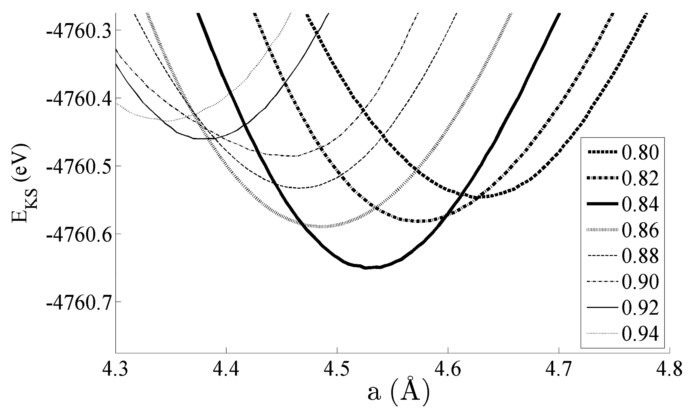
Figure 3.
The effects of strain on the spin moment of the bulk CeNi5 system for the (a) Ce 6s, (b) Ce 4f, (c–e) Ni 4s, and (f–h) Ni 3d states. The legend in (a) shows the values of c used for each curve, and the same legend applies to every panel in this figure.
Figure 3.
The effects of strain on the spin moment of the bulk CeNi5 system for the (a) Ce 6s, (b) Ce 4f, (c–e) Ni 4s, and (f–h) Ni 3d states. The legend in (a) shows the values of c used for each curve, and the same legend applies to every panel in this figure.
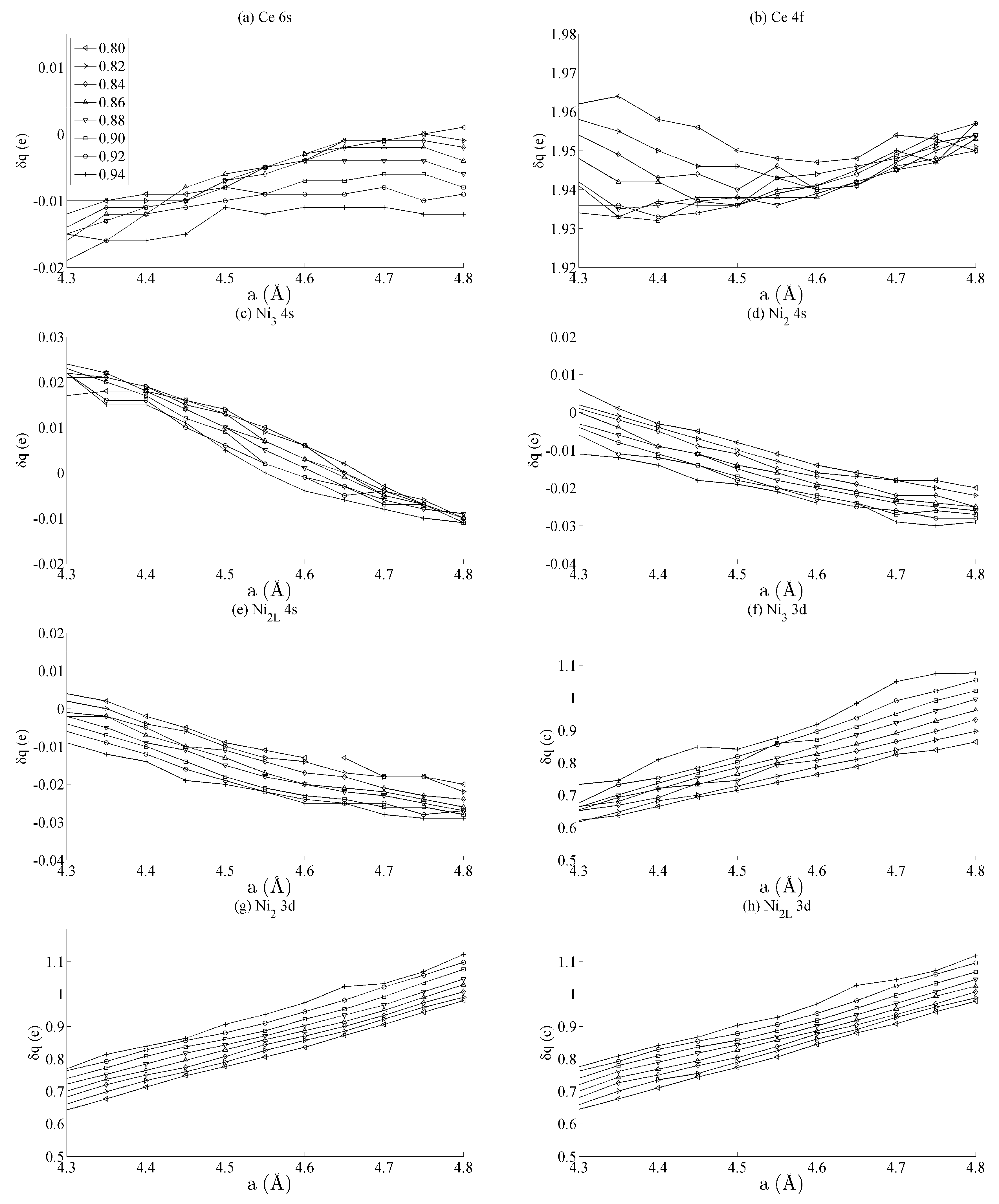
Figure 4.
The effects of basal strain on the projected density of states (PDOS) of bulk CeNi5 for the (a) Ce 6s, (b) Ce 4f, (c–e) Ni 4s and (f–h) Ni 3d states. Each panel shows spin-up and -down components in the PDOS > 0 and PDOS < 0 portions of the graph, respectively. Subsequent curves are offset vertically for clarity and were obtained using values of a = 4.00, 4.05, …, 5.00 Å. The curves obtained for a = 4.00 Å lie along the line PDOS = 0, and those for a = 5.00 Å lie furthest from this axis. For all the curves presented in this figure, c = 0.84.

Figure 5.
Bond orders (BO) of the state-resolved Ce–Ni interactions within the strained CeNi5 system for the (a) Ce 6s–Ni 4s, (b) Ce 6s–Ni 3d, (c) Ce 4f–Ni 4s and (d) Ce 4f–Ni 3d interactions. The ↑ and ↓ arrows denote BO estimated using the spin-up and -down components of the crystal orbital overlap population (COOP), respectively. The subscripts in each panel indicate the pair of atoms between which the BO has been evaluated. The legend in (a) shows the values of c used for each curve, and the same legend applies to every panel in both Figure 5 and Figure 6.
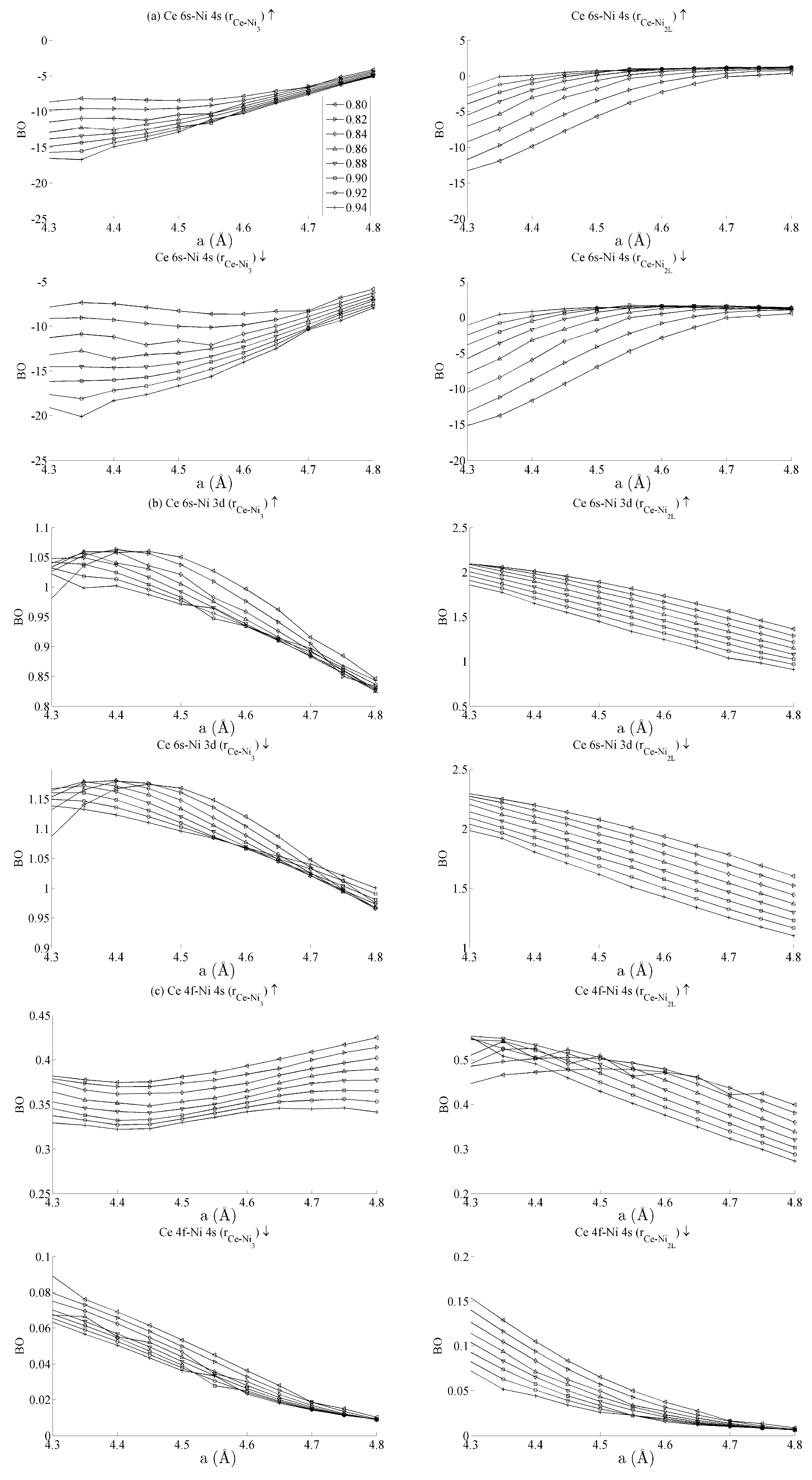
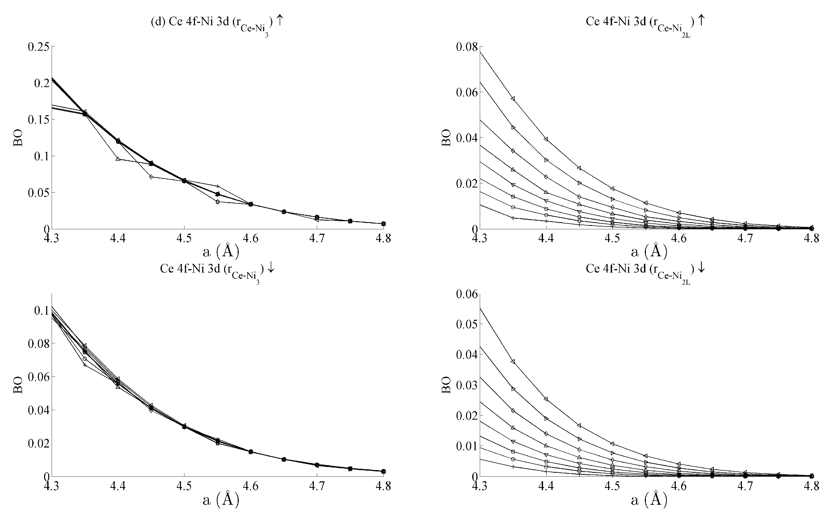
Figure 6.
Bond orders (BO) of the (a) Ni 4s–Ni 4s, (b) Ni 4s–Ni 3d, and (c) Ni 3d–Ni 3d interactions within the strained CeNi5 system. The ↑ and ↓ arrows denote BO estimated using the spin-up and -down components of the crystal orbital overlap population (COOP), respectively. The legend in Figure 5a defines the values of c used for each curve.


Table 1.
Summary of the average Ce–Ni bond order and its standard deviation for the strain states of the CeNi5 system defined in Figure 5. The most significant BO are highlighted.
| Interaction | r | Spin | ||
|---|---|---|---|---|
| Ce 6s–Ni 4s | Ce–Ni3 | ↑ | −12.5 | 5 |
| Ce–Ni2L | ↑ | −5.0 | 6 | |
| Ce–Ni3 | ↓ | −12.4 | 5 | |
| Ce–Ni2L | ↓ | −5.0 | 6 | |
| Ce 6s–Ni 3d | Ce–Ni3 | ↑ | 0.9 | 0.1 |
| Ce–Ni2L | ↑ | 1.5 | 0.5 | |
| Ce–Ni3 | ↓ | 1.05 | 0.1 | |
| Ce–Ni2L | ↓ | 1.75 | 0.75 | |
| Ce 4f–Ni 4s | Ce–Ni3 | ↑ | 0.35 | 0.05 |
| Ce–Ni2L | ↑ | 0.40 | 0.15 | |
| Ce–Ni3 | ↓ | 0.04 | 0.04 | |
| Ce–Ni2L | ↓ | 0.075 | 0.075 | |
| Ce 4f–Ni 3d | Ce–Ni3 | ↑ | 0.1 | 0.1 |
| Ce–Ni2L | ↑ | 0.05 | 0.03 | |
| Ce–Ni3 | ↓ | 0.05 | 0.05 | |
| Ce–Ni2L | ↓ | 0.03 | 0.03 |
Table 2.
Summary of the average Ni–Ni bond order and its standard deviation for the strain states of the CeNi5 system defined in Figure 6. The most significant BOs are highlighted.
| Interaction | r | Spin | ||
|---|---|---|---|---|
| Ni 4s–Ni 4s | Ni3–Ni2 | ↑ | −40 | 20 |
| Ni2L–Ni2 | ↑ | −15 | 15 | |
| Ni3–Ni2 | ↓ | −40 | 40 | |
| Ni2L–Ni2 | ↓ | −20 | 20 | |
| Ni 4s–Ni 3d | Ni3–Ni2 | ↑ | 9 | 3 |
| Ni2L–Ni2 | ↑ | 3.25 | 0.5 | |
| Ni3–Ni2 | ↓ | 10 | 2 | |
| Ni2L–Ni2 | ↓ | 4 | 0.6 | |
| Ni 3d–Ni 3d | Ni3–Ni2 | ↑ | 3 | 2 |
| Ni2L–Ni2 | ↑ | 0.75 | 0.65 | |
| Ni3–Ni2 | ↓ | 7.5 | 5 | |
| Ni2L–Ni2 | ↓ | 1.75 | 1.25 |
© 2016 by the author; licensee MDPI, Basel, Switzerland. This article is an open access article distributed under the terms and conditions of the Creative Commons Attribution (CC-BY) license (http://creativecommons.org/licenses/by/4.0/).
Share and Cite
MDPI and ACS Style
Shuttleworth, I. Strain Engineering of the CeNi5 System. Magnetochemistry 2016, 2, 39. https://doi.org/10.3390/magnetochemistry2040039
AMA Style
Shuttleworth I. Strain Engineering of the CeNi5 System. Magnetochemistry. 2016; 2(4):39. https://doi.org/10.3390/magnetochemistry2040039
Chicago/Turabian StyleShuttleworth, Ian. 2016. "Strain Engineering of the CeNi5 System" Magnetochemistry 2, no. 4: 39. https://doi.org/10.3390/magnetochemistry2040039
Note that from the first issue of 2016, this journal uses article numbers instead of page numbers. See further details here.