Article

Durability and Reliability of Electric Vehicle Batteries under Electric Utility Grid Operations. Part 1: Cell-to-Cell Variations and Preliminary Testing

Hawai‘i Natural Energy Institute, University of Hawai‘i at Mānoa, Honolulu, HI 96822, USA
*
Author to whom correspondence should be addressed.
Batteries 2016, 2(3), 28; https://doi.org/10.3390/batteries2030028
Submission received: 24 May 2016 / Revised: 16 August 2016 / Accepted: 22 August 2016 / Published: 9 September 2016
(This article belongs to the Special Issue Lithium Ion Batteries)

Abstract

:
Vehicle-to-grid (V2G) and grid-to-vehicle (G2V) strategies are considered to help stabilize the electric grid but their true impact on battery degradation is still unknown. The intention of this study is to test the impact of such strategies on the degradation of commercial Li-ion batteries. This first part looks into the preliminary testing performed prior to the start of degradation studies to ensure that the selected cells are compatible. Both the thermodynamic and kinetic cell-to-cell variation within the selected batch and the diagnostic-ability of the cells were investigated. The cells were found to have low cell-to-cell variations and are thus consistent. Moreover, the emulation of the full cell from the half-cell data prepared from harvested electrodes was successful and the degradation forecast showed that the main degradation modes can be differentiated.

1. Introduction

Electric vehicles (EVs) and renewable energy sources have the potential to substantially decrease carbon emissions from both the transportation and power generation sectors. Mass adoption of EVs could have a number of impacts, including the ability to ease the integration of intermittent renewable energy into existing electric grids. With the right infrastructure in place, batteries of parked EVs could be used to supply energy to the grid in a scheme known as vehicle-to-grid (V2G) and/or to store excess energy from the grid in a scheme known as grid-to-vehicle (G2V). The potential technical and commercial benefits of V2G and G2V have been heavily investigated in recent years [1,2,3,4,5,6,7,8,9,10,11,12] for load shifting [3,4,5], charging/discharging optimization [6,7], reserve [8], cost [9] or integration on a smart grid [1,10,11,12]. One key parameter to weigh in the viability of V2G and G2V is the degradation of the batteries induced by the additional usage. The success of V2G/G2V strategies will depend on consumer acceptance and desire to participate in the program. It is therefore essential to compare the reward—the financial gain from “selling” some of stored EV battery charge back to the grid utility, to the risk—a potential faster degradation of the battery that would reduce lifetime. The literature on the subject is limited as most studies are using inaccurate battery models to address the issue [1,2,13,14,15,16,17,18,19] and not actual battery testing data [20,21]. Although some modeling studies stands out (e.g., [19]), only one study by Peterson et al. [20] appears to address this issue via the actual testing of commercial lithium-ion batteries. They concluded that constant current (CC) V2G had little effect on the cells, but the battery cells tested were lithium iron phosphate, which are seldom used in commercial EVs. In addition, because the authors only considered one set of conditions, the combined effects of V2G and G2V strategies were not assessed.
The overall goal of this research effort is to study the impact of V2G and G2V strategies on the degradation of commercial Li-ion cells comparable to those used in EVs. This paper focuses on the preliminary testing as the first step in broader degradation studies. The aim of this preliminary testing was to verify two critical requirements for the V2G and G2V impact study: (1) the use of cells with a low intrinsic variability; and (2) the ability to perform advanced diagnosis of these cells without the need for post mortem studies. Later work will involve the testing of more than 50 cells under a matrix of 20 different aging scenarios. It is therefore essential to establish that differences in outcomes of the degradation diagnosis are associated with the duty cycles rather than intrinsic variability. It is also critical to establish a systematic online diagnosis method because the sheer volume of cells to analyze makes relying on postmortem techniques impractical.
In order to address the first point, the intrinsic variability within the cells, this work will address the cell-to-cell variations of the entire batch of cells. The literature has discussed characterization of cell-to-cell variations [22,23,24,25,26] and we proposed a methodology to perform such characterization [26] that could be used independently of the cells application [27,28]. We believe this methodology is well suited for this study and in addition we introduce here a new methodology that adds the quantification of thermodynamic balance differences to the established metrics. Proper analysis of formation test is the foundation of successful extensive battery testing studies with multiple testing conditions. It allows excluding outliers, to provide an idea of the reproducibility of the results beforehand and to select cells with similar characteristics for the following degradation studies.
In order to address the second point, advanced diagnosis without the need for post mortem studies, the cell degradation mechanisms will be deciphered using computer assisted incremental capacity (IC) analysis and the detailed electrochemical signature of a Panasonic commercial graphite/LiNixCo1−xyAlyO2 (NCA) cell will be investigated for the first time. IC is a non-destructive technique that was proposed by Balewski and Brenet for half cells in the late 1960s [29]. We pioneered its application to full cell degradation understanding in the late 2000s [30,31]. The computer assisted analysis was proposed in 2012 [32] and it relies on the assembly of an emulated replica of the full cell built from half-cell data harvested from both electrodes. This work will highlight the development of the emulated version and the visualization of the impact of degradation on the cell to be used later on for diagnosis.

2. Materials and Methods

A batch of 100 Panasonic Cylindrical 3350 mAh NCR 18650B (Ozaka, Japan) was purchased for this study. These cylindrical 18,650-size graphite/NCA cells were chosen because they are consistent with the type of cells found in some EVs such as Tesla’s Model S [33,34]. Upon initial survey, the cells were weighed and their open circuit potentials were recorded. The cells were then subjected to a conditioning process using a series of C/2 discharge regimes to the discharge cut off of 2.5 V, which was terminated when the capacity stabilized within ±0.2% between two consecutive cycles. All cells were recharged according to manufacturer specifications using a CC step at C/2 rate to the cut off voltage of 4.2 V, followed by a constant voltage (CV) step until the termination current of 65 mA (C/50) was reached. The cells were typically conditioned within three to six cycles.
After completion of the conditioning, the cells were subjected to the initial conditioning and characterization test (ICCT). The purpose of this test is to ensure that the cells will perform according to their specifications and to assess the cell quality compared to other cells from the same manufacturer [26]. The ICCT consists of two discharge regimes at C/5 and C/2 with a 4-h rest between charge and discharge regimes to determine the cells rest cell voltages (RCV) at the beginning of each regime. The cells were recharged according to manufacturer specifications. The ohmic resistance of the cells was estimated from the difference in IR drops among the C/5 and C/2 discharges using Ohm’s law; i.e., ΔV = R·ΔI. After these tests, the cells were recharged to 50% state of charge (SOC) for storage at −27 °C in a freezer.
A “nominal sample cell” was selected from the batch and subjected to additional cycling at C/40, C/20, C/10, C/5, C/3, C/2, C/1, 2C and 3C to determine its performance characteristics. Additionally, 50 cells were subjected to C/35, C/5 and C/3 cycles. In all of these cycles, the cell was charged and discharged at specific rates in-between the cutoff conditions, 4.2 V in charge, 2.5 V in discharge. A 4-h rest was imposed to the cell at end of charge (EOC) and end of discharge (EOD) for each given rate to measure the RCV. Remnant capacity was measured following any regime with a C/50 discharge or charge step to the same respective cutoff condition, followed by another 4-h rest and RCV measurement. This second set of RCV shall be used to decipher the SOC of the starting point for the next regime, noted either as the beginning-of-charge (BOC) or as the beginning-of-discharge (BOD), when appropriate. To determine the SOC, we used a method described in our previous work [27,30], which uses the pseudo-open circuit voltage (OCV) curve versus SOC curve for this chemistry (denoted as ps-OCV = f(SOC)). The ps-OCV = f(SOC) curve is derived as follows: (1) normalize the nominal sample cell C/40 charge and discharge curves; and (2) take the average of the voltage curves in the charge and discharge regimes. The SOC can be determined by looking up the corresponding RCV on the ps-OCV = f(SOC) curve. All tests were carried out on a calibrated 40 channel Arbin LBT-5V-25A battery tester (College Station, TX, USA).
Our diagnosis methodology requires harvesting the electrodes of a fresh cell to cycle them against a lithium reference/counter electrode. In order to do so, another cell from the batch was first fully discharged to 2 V using a CC/CV technique with a C/200 limiting current. Placed in an argon atmosphere glove box for disassembly, both end caps of the 18650 cell were cut using a pipe cutter and a rotary tool equipped with a diamond coated cutting disc was used to cut a straight line along the central cylinder to free the “jelly roll” of electrodes. Since commercial electrodes are double sided, the active material layer on one side of each electrode must be removed for half-cell testing. This was done by gently rubbing the electrodes with a cotton tip soaked in solvent. To avoid solvent seepage to the other side on which the electrochemical measurements are to be made, solvent was applied only to the inner section of the electrode cutout, so the edges remained untouched by the solvent. Moreover, to further decrease further the risk of electrode contamination from the disassembling process, electrodes discs (with an area of 0.97 cm2) were punched near the center of the electrode roll. Finally, the electrodes were rinsed in fresh dimethyl carbonate (DMC) to remove any trace of lithium salt.
Electrochemical analyses were performed in Swagelok type cells (1/2″ polytetrafluoroethylene-type) with a lithium metal-coated stainless steel disk as counter electrode and two layers of Whatman GF/D borosilicate glass fiber disk (Little Chalfont, UK) as separator. The electrolyte consisted of a 1 mol·L−1 of LiPF6 in 1:1 (by weight) ethylene carbonate/DMC solution with 2 wt% vinylene carbonate additive.
Electrochemical measurements were carried out using a multichannel potentiostat from Bio-Logic (VMP3, Claix, France). The Swagelok cells underwent conditioning and reference performance testing. The positive electrode (PE) was cycled from 4.35 V to 3.0 V. Its conditioning cycles consisted of 1 charge/discharge cycle at a C/45 rate, followed by 6 cycles at a C/3.5 rate. The graphite intercalation compound (GIC) electrode was cycled from 0.01 V to 1.2 V, and its conditioning consisted of 1 cycle at a C/30 rate followed by 5 cycles at a C/25 rate. These conditioning cycles on both electrodes were followed by a reference performance test (RPT) that consisted of a sequence of charge/discharge cycles at different rates: C/40, C/20, C/10, C/5, C/2 and C/1.
Computer simulations were performed using the 'Alawa toolbox (Hawai‘i Natural Energy Institute (HNEI), Honolulu, HI, USA), a graphical interface for the mechanistic diagnosis model we proposed in 2012 [32,35]. This emulation approach, based on the matching of electrode half-cell data, has received experimental validation recently by other groups [36,37] and some example of its capabilities can be found in our previous work [38,39,40,41].
The complete dataset used in this work is available on Zenodo [42] (European Organization for Nuclear Research (CERN), Geneva, Switzerland).

3. Results

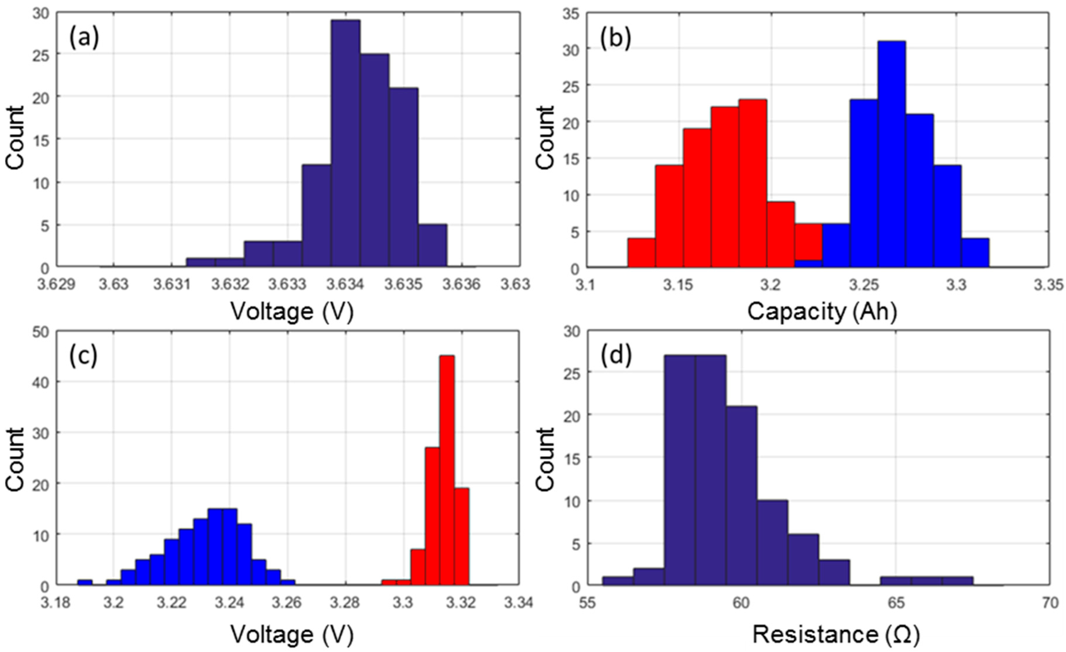
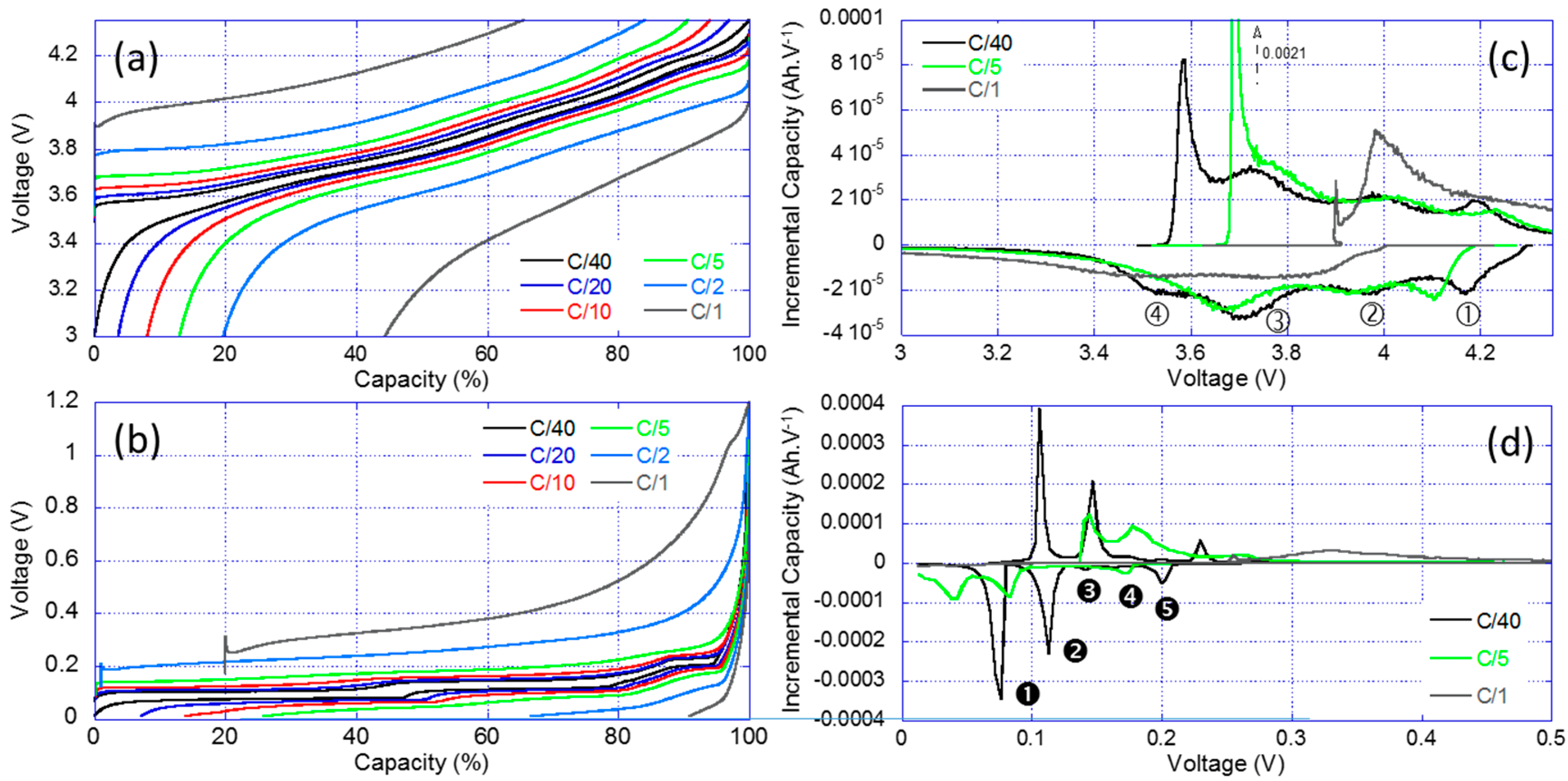
3.1. Formation Cycles Testing

Prior to the start of the ICCT, the cells were weighed and the as-received OCV was recorded. The average weight was 45.870 g with a 0.16% standard deviation and the weights follow a close to normal distribution. The average as-received OCV was of 3.634 V with a 0.02% standard deviation (Figure 1a). The distribution was found to be asymmetrical and two outliers were identified with lower as-received OCVs.
The ICCT consisted of two discharges at C/5 and C/2 with rest periods and manufacturer charge protocol. Using information gathered from these two discharges it is possible to compare capacities (Figure 1b), RCV (Figure 1c) and the ohmic resistance (Figure 1d).
Looking at the capacity retentions, the cells delivered on average 3.269 Ah when subjected to a C/5 rate and 3.177 Ah when subjected to a C/2 rate. The standard deviation of the C/2 discharges was slightly higher (0.8% versus 0.6%) than it was for the C/5 discharges. Both capacity distributions were close to normal but with two outliers with higher capacities (Figure 1b). The next parameters to investigate were the RCV at the beginning and at the end of both discharge regimes. Since the cells were charged with the same protocol prior to the C/5 and the C/2 discharges, the RCV at BOD were similar for both discharge regimes, 4.174 V on average with a 0.04% standard deviation. At EOD, there was an effect of the discharge rate and the EOD RCVs were of 3.231 V (±0.41%) and 3.314 V (±0.14%) for the C/5 and C/2 discharges, respectively. The distributions were found to be asymmetrical and broader towards the lower potentials (Figure 1c). The last parameter to investigate was the distribution of ohmic resistances calculated from the voltage drop induced by the application of current at the beginning of both the low rate and the high rate discharges [26]. The average ohmic resistance was 59.6 mΩ with 2.95% standard deviation. The resistance distribution exhibits a right skewed shape, which would indicate that there exist a minimal achievable resistance and that the variability in the production process can only contribute additively to this optimal minimal resistance. In addition, three clear outliers were identified with a resistance 5%–10% higher than that of the other cells in the batch (Figure 1d).

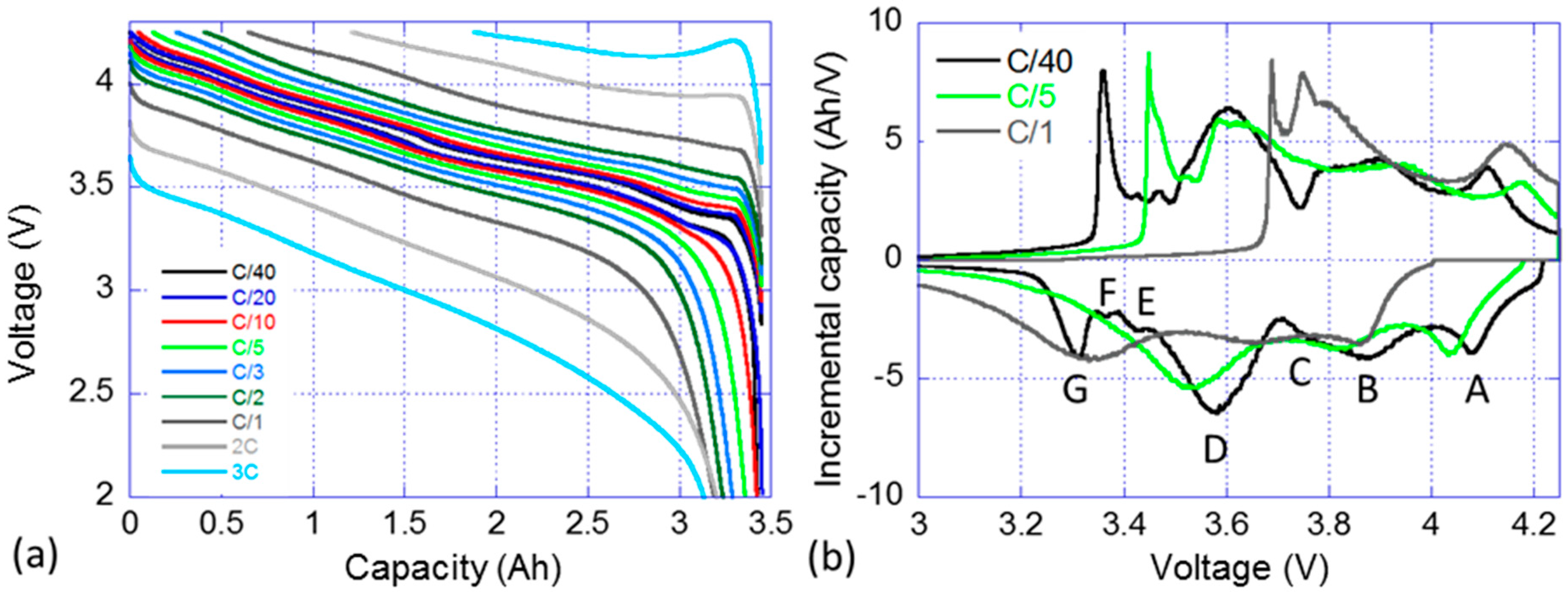
3.2. Nominal Sample Cell Reference Performance Testing

A nominal sample cell from the batch was subjected to a RPT with cycling at rates ranging from C/40 to 3C. Figure 2a presents the voltage versus capacity response of the cell and Figure 2b the IC signature of the C/40, C/5 and C/1 cycles. Figure 2a displays that the selected cell can handle discharge rates up to 3C while retaining more than 90% of its capacity. The capacity in charge is however clearly limited by the polarization resistance and the voltage window. It is decreasing linearly with the increase of the rate and a C/1 charge can only recover 80% of the maximum discharge capacity and the percentage goes down to 45% for a 3C charge. The IC signature of the cell is rather complex, Figure 2b, and seven features can be identified on the C/40 charge and discharge curves. The first three features, labeled A, B and C, correspond to broad electrochemical peaks at high voltage. Feature A is associated with the peak which intensity maximum is located around 4.080 V in discharge. Features B and C refer to two overlapping peaks that are close in potential, with maximum intensities around 3.880 V and 3.770 V, respectively. Feature D correspond to the largest observable IC peak which a maximum intensity at approximately 3.6 V. Finally, Features E–G corresponds to three sharp peaks at low potential. When the current increase from C/40 to C/5 then C/1, the IC peaks become broader and Features E and G are no longer visible in the discharge regime, whereas Feature G is still clearly visible in the charge regime.

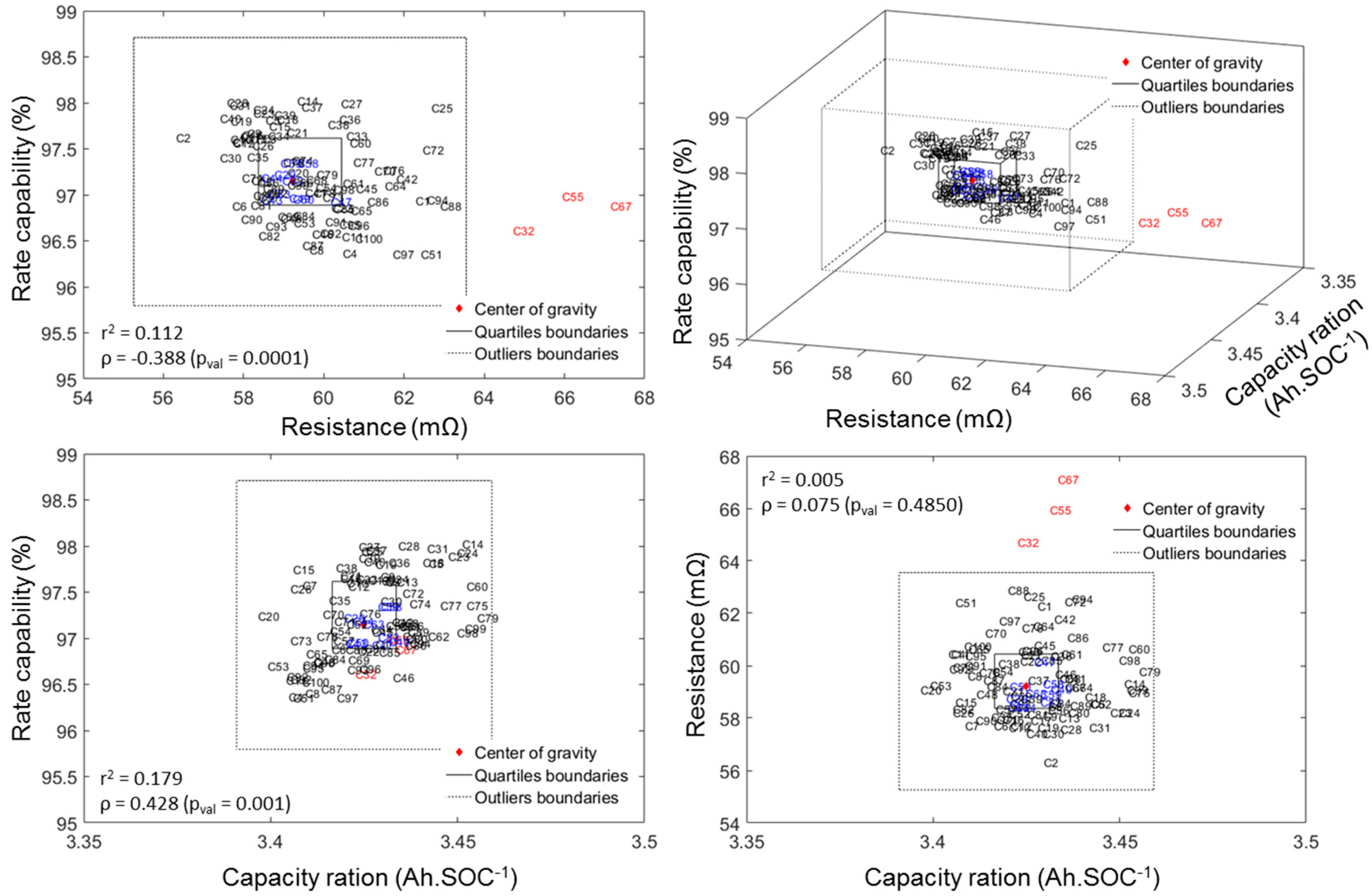
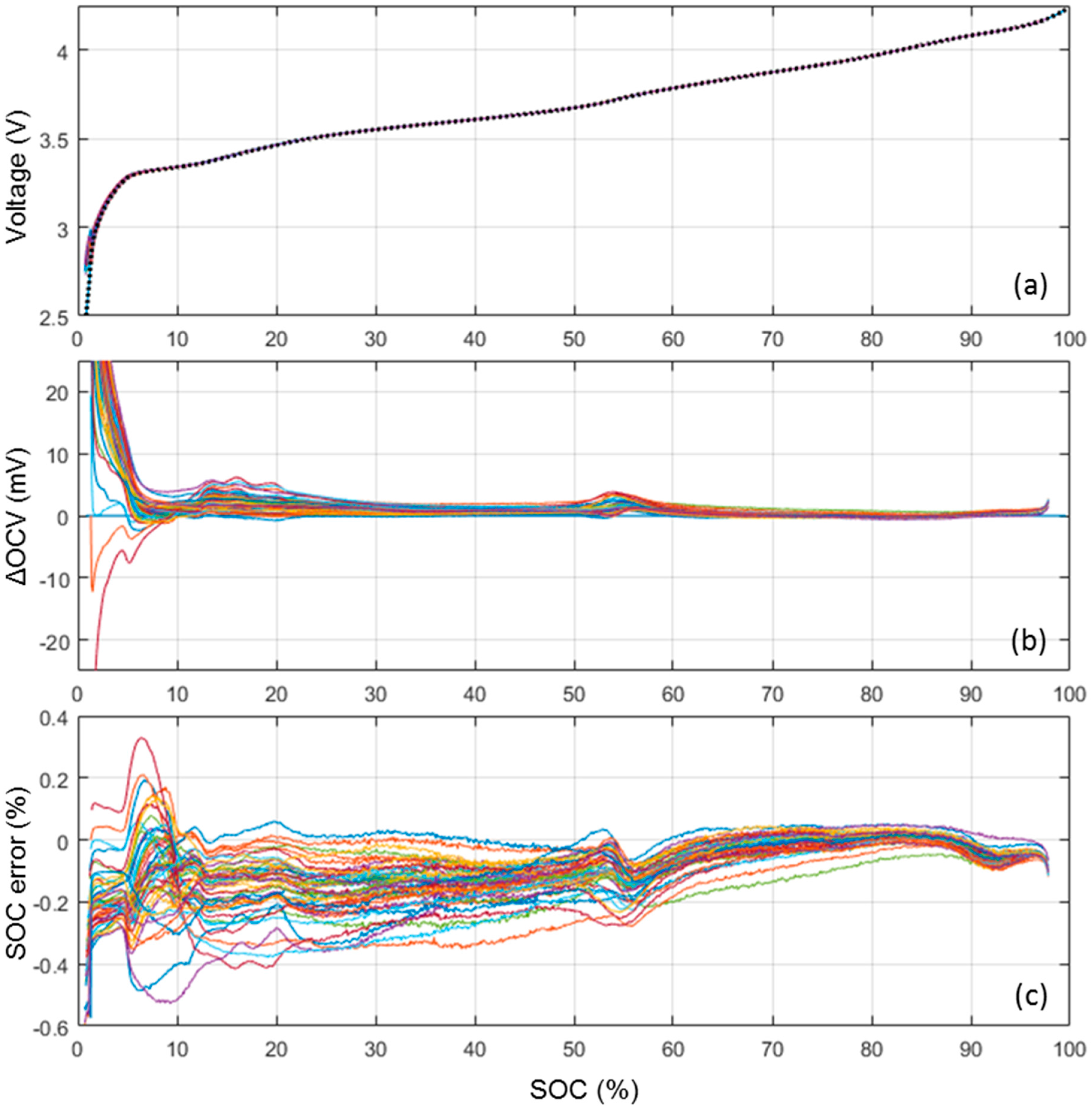
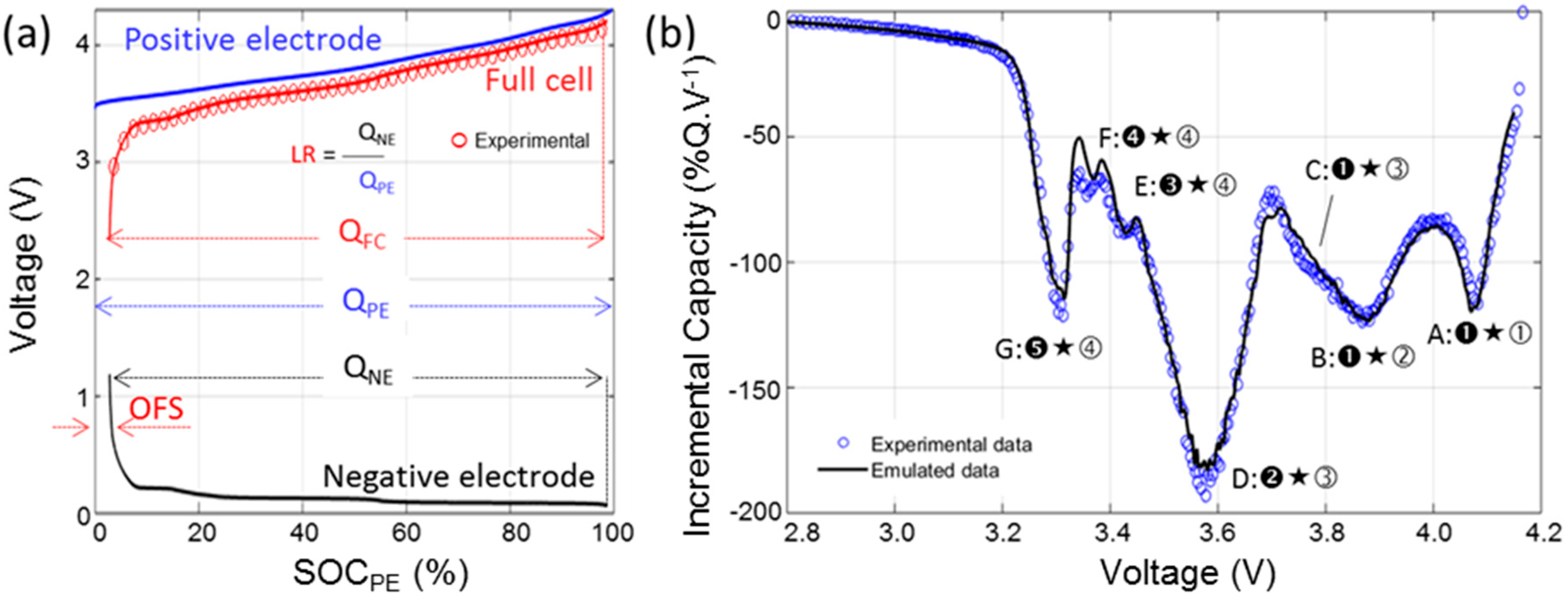
3.3. ps-OCV = f(SOC) Curve Cell-to-Cell Variations

Figure 3a presents a comParison of the ps-OCV = f(SOC) curves calculated from the nominal sample cell (dotted line) C/40 cycle and from the 50 cells that experienced a C/35 cycle. At the scale of the voltage versus SOC curve, the 51 ps-OCV = f(SOC) curves are virtually undistinguishable. In order to enhance the differences between the curves, Figure 3b plots the voltage difference between the 50 ps-OCV = f(SOC) curves calculated from the C/35 cycles and the one calculated from the C/40 cycle. The voltage error is 1 mV or below for the most of the SOC range with some slight increase to at most 3 mV in the 60%–50% and 6 mV in the 20%–10% ranges and some more significant increase to more than 20 mV below 5% SOC. Those variations are likely induced by slightly different electrode loading and/or some inhomogeneities between cells in the initial solid electrolyte interphase (SEI) formation. Independent of their origin, these variations will induce some SOC estimation errors. In order to estimate the impact of these variations on the SOC estimation, the associated error was calculated, Figure 3c. The error was defined for each SOC as the SOC difference between the actual SOC and the SOC associated with the corresponding OCV plus the voltage variation. The average error was −0.01% with a 0.1% standard deviation and the maximum error was 0.5%. The ps-OCV = f(SOC) curve calculated form the C/40 cycle can thus be considered universal and representative of all the cells in the batch.

3.4. Half-Cell Testing

The results of the RPT for the PE and the negative electrode (NE) individually are shown in Figure 4. Figure 4a showcases the traditional voltage versus capacity curves highlighting the changes in electrochemical response with the increase of the current for the PE. The more current was passed through the cell, the less capacity was available and the more polarization was present. For example, at C/1, the PE only delivered approximately 60% of the low rate capacity and it presented a 400 mV higher polarization. Figure 4b presents the IC derivative of the data in Figure 4a. The IC signature of the PE is compatible with literature data on the NCA chemistry and four IC peaks labeled ①–④ can be observed. There were some kinetic limitations towards the end of the charge and the end of the discharge regimes. This induces a great asymmetry between the charge and discharge curves at low and high voltages. There was also an energy activation barrier to start the charging process (removing Li-ions from the structure), this explain the shape and the intensity of the low voltage peak ④ in charge. The same thing was observed in the full cell IC curve (Figure 2b, Feature G). Figure 4c,d presents the same plots for the NE. The IC signature of the NE is compatible with literature data on the graphite chemistry with five peaks noted ➊–➎ [43,44].

4. Discussion

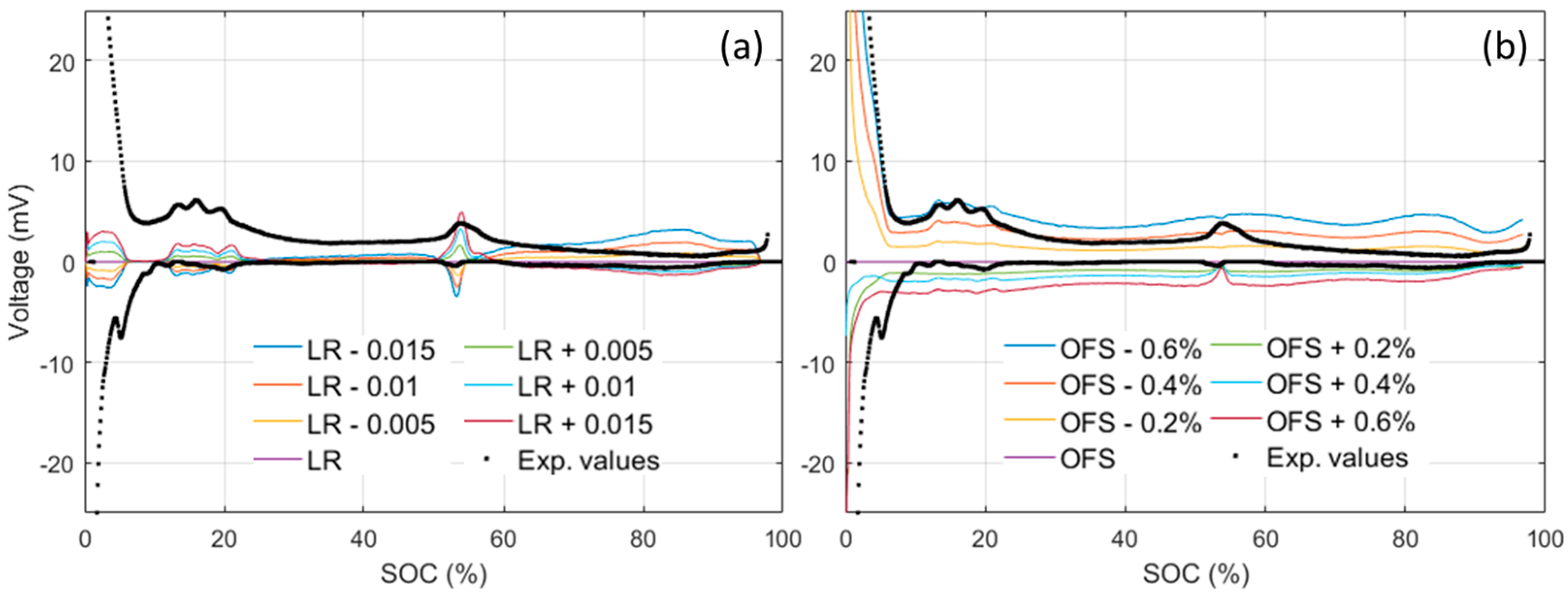
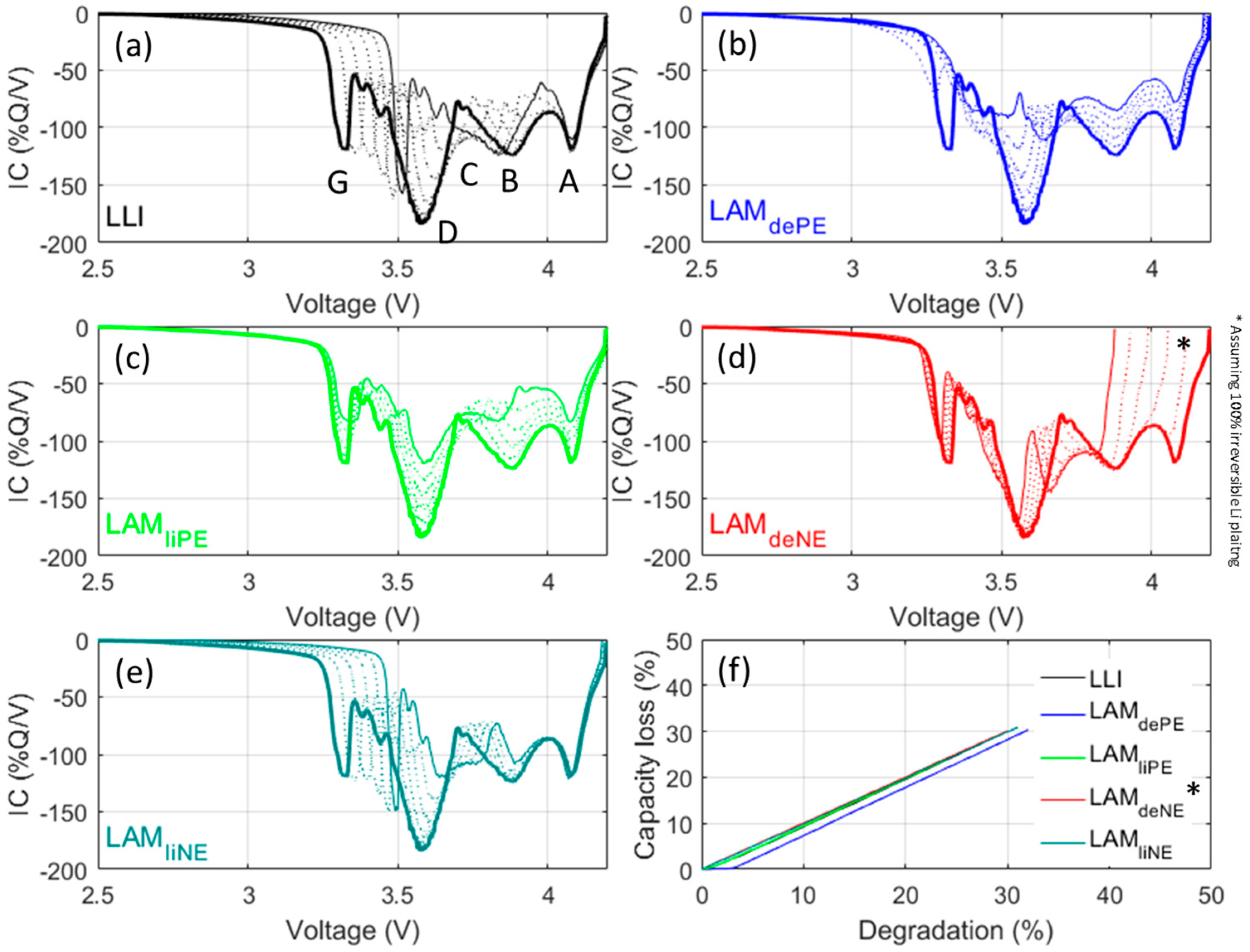
4.1. Cell-to-Cell Variations

As described in our previous study [26], the three attributes that can be used to quantify the cell-to-cell variations are the rate capability, the capacity ration and the ohmic resistance:
Rate capability (%): The rate capability represents the cell’s ability to deliver stored capacity when the discharge rate increases. In this study, it was calculated by dividing the capacity returned at C/2 by the capacity returned at C/5.
Capacity ration (mAh/%SOC): The term “capacity ration” is the capacity (Ah) obtained for each one percent of the SOC. It typically reflects the amount of active material in a cell. RCV measurements at the BOD and the EOD are used to derive a SOC range by interpolation of the maximum and minimum SOCs (e.g., 99.7%–3.2%). The capacity ration can then be calculated by dividing the capacity by the SOC range.
Ohmic resistance (Ω): The ohmic resistance consists of the contact resistance of the cell in the circuit and the conductive resistance of the cell (which primarily comes from the electrolyte). It is calculated using the initial voltage drop associated with the C/2 and C/5 discharges.
The rate capability was found to be 97.2% ± 0.46% on average, the capacity ration 3.43 mAh·SOC−1 ± 0.46%, and the ohmic resistance 59.6 mΩ ± 2.95%. Compared to published values for other batches of cells, these standard deviation values are rather small [27,28]. The cells are therefore highly consistent (high quality of manufacturing) and ideal for the study to be undertaken.
A good way to visualize the quality of the batch is to plot the data in a 3D plot with associated top/side/front projections in which the three axes represent the three attributes to the cell-to-cell variations (Figure 5). The two cubes (squares in top/side/front projections) in Figure 5 represents the inner quartile range (IQR, with the thick line) and the outlier boundary (with the dotted line). The IQR is defined as the difference between the upper and lower quartiles (UQ and LQ), which separate the lowest 25% and the highest 75% of the data. Cells that fell in the IQR for all three attributes are color-coded in blue, whereas the rest of the cells appear in black for non-outliers or red for outliers. The outlier boundaries are defined by the generally accepted LQ − 1.5(IQR) for the lower limit and UQ + 1.5(IQR) for the higher limit as proposed by Tukey [45]. From Figure 5 it appears that our batch of cells only contains three outliers (in red) and that they are only outliers in terms of ohmic resistance. These cells will not be used in this study. Interested readers can refer to our Electric Vehicle Transportation Center (EVTC) Report [46] for more details on the ICCT analysis.
From Figure 5 above, a correlation analysis on the three attributes of cell-to-cell variations can be undertaken in order to determine if the attributes are correlated. There are several correlation coefficients, often denoted by the Greek letter ρ, measuring the degree of correlation and the most common is the Pearson correlation coefficient, which is sensitive only to linear relationships. To avoid this limitation, the Spearman’s rank correlation that is sensitive to any monotonic correlation was used in this work. The correlation coefficient is comprised between +1, in the case of a perfect direct (increasing) relationship, and −1 in the case of a perfect decreasing (inverse) relationship. The closer to zero, the more the variables are uncorrelated. Additionally, the p-values were calculated for each correlation. P-values were calculated to test the hypothesis of no correlation against the alternative that there is a nonzero correlation. If the p-value is small, e.g., less than 5%, then the correlation is significantly different from zero. The value of the correlation coefficient as well as the r2 and the associated p-values are reported on the top/side/front projections on Figure 5.
From these values, it appears that there is no correlation between the capacity ration and the resistance (low ρ and high p-value) but there seems to be a slight correlation between the resistance and the rate capability and between the rate capability and the capacity ration (both have medium ρ and low p-value). Both the absence of correlation between capacity ration and resistance and the correlation between resistance and rate capability were expected: capacity ration reflects the thermodynamic maximum capacity and should be unaffected by kinetics; also a higher resistance is likely to lower the capacity available at high rates and thus impact the rate capability. The last one, the correlation between rate capability and capacity ration, is interesting because it could give some insights on the origin of the cell-to-cell variations. Higher capacity ration could originate from two sources: longer jelly roll and heterogeneities in additive content or active particle size. Under the first scenario, a longer jelly roll implies that more surface could react and therefore result into a lower current density on the electrode (same applied current on the cell but more surface). This could in return induce a higher rate capability. Under the second scenario, the higher capacity ration would be introduced by a larger active material loading per unit area of electrode. This should reduce either the porosity or the additive content and in return lower the rate capability because the power ability of the cell would be reduced. Given the observed direct correlation (higher rate capability for higher capacity rations), the scenario where electrodes are uniform across cells but of slightly different lengths seems more likely.

4.2. Cell Emulation

The half-cell RPT data was imported in the 'Alawa toolbox [35] in order to be able to emulate the full cell behavior from the half-cell data [32,41]. Matching the electrodes depends mainly on two parameters: the initial loading ratio (LR) and offset (OFS). LR corresponds to the ratio between the two electrodes capacities. OFS corresponds to the shift between the electrodes induced by parasitic reactions during the cell formation (initial SEI growth and/or irreversible material loss). Figure 5a illustrates the definition of the LR and the OFS and Figure 5b showcases the results of the emulation. The LR was estimated at 0.96, the OFS at 2.8%. Since the half-cell data were collected using a different electrolyte and different separators from that of the full cell, some additional minor adjustments were necessary and the electrodes kinetics were accelerated by a factor 2.
Once the emulation is completed, the emulated cell can be used to understand the IC signature of the cell better, estimate the OCV cell-to-cell variations and predict the signature of the main degradation modes.
To better understand the IC signature of the cell, each of the seven features observed on the full cell IC curve (Figure 2b) can be associated with the corresponding electrochemical reactions in each electrode (Figure 4b,d and Figure 6b). To index the peaks in function of their distinctive reactions in the electrodes, the following convention will be used: (1) an IC peak represents a reaction on the NE occurring at the same time than a corresponding one on the PE; (2) the NE reaction is denoted by a black (filled) numbering, while the positive with an open (unfilled) one; and (3) “★” will be used to separate the NE and PE reaction number to denote the convolution between the negative and positive IC signals that results in the unique IC peak in the cell. The first three Features, A, B and C, are primarily influenced by the PE (Reactions ①–③) since they all occur under the same electrochemical reaction on the NE (➊). These features will therefore be a good indicator for any degradation of the PE. The last three Features E, F and G all occur under a single reaction on the PE (④) but under several reactions on the NE (Reactions ➌–➎). They will therefore be a good indicator of the degradation of the NE. The last Feature D corresponds to Reaction ➋ on the NE and ③ on the PE.
To estimate the OCV variations, simulations can be performed with various LR and OFS and the obtained OCVs can then be compared to the one obtained from Figure 6a. The evolution of the OCV difference in function of the SOC is presented in Figure 7. For small variations, the obtained curves resemble the one observed experimentally (Figure 3b). LR variations (Figure 7a), mostly affect the 10%–20%, 50%–60% and >65% SOC window, whereas OFS variations affect mostly the SOC below 10% with an almost constant background above. Comparing the observations from Figure 7 to Figure 3b, it appears that the experimental variations in the 10%–20% window, below 5% SOC, and the background were likely introduced by OFS variations of between ±0.2% and ±0.4%, whereas the variations in the 50%–60% SOC window were likely introduced by ±0.005 LR variations. The OFS is mainly influenced by loss of lithium inventory (LLI) [32] and the small observed variations were therefore likely introduced by different lithium consumption during the SEIs formation [43,44] that could also affect how much of the NE is going to be active and thus the LR. According to the values above, we can estimate that, within the 51 tested cells, there is a spread of at most 0.8% in the amount of Li-ion consumed during formation and of less than 1% in the loss of NE active material.
To estimate the impact of degradation on the cell, the 'Alawa toolbox’s capability can be fully utilized to emulate degradation features. Since it was intended to reach quantitative assessment on capacity fade of thermodynamic origins, C/35 emulations, which are supposed to have minimal kinetic effects, were conducted. Thermodynamic cell degradation is usually associated with LLI and loss of active material (LAM). LLI encompasses all physicochemical phenomena where a Li+ ion, while on a course from one electrode to the other, ends up in a parasitic reaction instead of being intercalated into the destination electrode. Consequently, the lithium composition decreases in the source electrode (i.e., SOC increases) whereas the lithium composition of the destination electrode remains unchanged (i.e., no change in SOC). This SOC shift results into a modification of the thermodynamic balance of the cell. LAM refers to all physicochemical phenomena where some of the intercalation sites become inactive (e.g., ionic and/or electronic insulation, structural change, etc.). Losing sites will reduce the electrode’s ability to store charges and results in a modification of the thermodynamic balance of the cell. LAM can be categorized into four subsidiary modes (LAMliPE, LAMdePE, LAMliNE, and LAMdeNE) depending on which electrode (PE or NE) is affected and in which lithiation state (lithiated or delithiated). In total and including LLI, there are five degradation modes that have thermodynamic origins. Figure 8 forecasts the outcomes of the five modes with up to 30% of degradation with 5% increments.
Each degradation mode exhibit a unique degradation signature, which will provide useful clues to identify degradation mechanisms in further studies using these cells. LLI (Figure 8a) results mainly in a shift of Feature G towards higher potentials, whereas Feature D is disappearing. LAMdePE (Figure 8b) results in the intensity decrease of all peaks and the disappearance of Feature G. LAMliPE (Figure 8c) also results in a decrease of intensity for all peaks but Features G and D are less affected. LAMdeNE (Figure 8d) results in the disappearance of Feature A and the shift of all the other peaks towards lower potential. The disappearance of Feature A opens the door for Li plating that is likely to occur concurrently to the LAMdeNE [32]. If part of the plating is reversible, a new peak will appear at higher potential. LAMliNE (Figure 8e) is characterized by a shift of peak G towards higher potentials whereas Feature D intensity is reduced. This signature is close to the one of LLI which is normal since LAMliNE can be dissociated into LLI + LAMdeNE. However, the signatures are different, as can be seen with Feature C, which is unaffected in the case of LLI but separated from Feature B in case of LAMliNE. Figure 8f presents the associated capacity losses. For the all degradation modes but LAMdePE, the capacity loss is directly proportional to the extent of the degradation mode. For LAMdePE there is slight delay for which the degradation is not inducing any capacity loss. This delay corresponds to the OFS, which can be seen as a lithium reserve for the PE [31,40].

5. Conclusions

In this study, we tested a batch of 100 cells of commercial graphite/NCA cells in order to assess the quality of the cells for a future study of the impact of V2G and G2V strategies on cell degradation. The cell-to-cell variation analysis showcased that the cells are of high quality with similar thermodynamic properties as well as less than 0.5% variation in rate capability and capacity ration and less than 3% variation in resistance. The selected cells are therefore perfectly suited for long term studies of cell tested under a range of aging scenarios such as V2G and G2V. Additionally, the electrochemical behavior of the cell was replicated under the 'Alawa toolbox. This successful emulation shall enable accurate diagnosis of cell degradation and shall permit comParison of cells following different degradation paths in future studies.

Acknowledgments

This work was supported in-part by an award from the Florida Solar Energy Center (FSEC), University of Central Florida, as part of Grant Number DTRT13-G-UTC51 from the U.S. Department of Transportation’s University Transportation Centers Program and by the Office of Naval Research (ONR) Hawaii Energy and Environmental Technologies (HEET) Initiative, Award Number N00014-11-1-0391. The authors are grateful to the Hawaiian Electric Company for their ongoing support to HiSERF operations. The authors are also thankful to Katherine McKenzie, Keith Bethune, Jack Huizingh and Richard Rocheleau (HNEI) as well as David Block and Paul Brooker (FSEC).

Author Contributions

Arnaud Devie and Matthieu Dubarry conceived and designed the experiments; Arnaud Devie performed the experiments; Arnaud Devie and Matthieu Dubarry analyzed the data; and Matthieu Dubarry wrote the paper.

Conflicts of Interest

The authors declare no conflict of interest.

References

  1. Mwasilu, F.; Justo, J.J.; Kim, E.-K.; Do, T.D.; Jung, J.-W. Electric vehicles and smart grid interaction: A review on vehicle to grid and renewable energy sources integration. Renew. Sustain. Energy Rev. 2014, 34, 501–516. [Google Scholar] [CrossRef]
  2. Habib, S.; Kamran, M.; Rashid, U. Impact analysis of vehicle-to-grid technology and charging strategies of electric vehicles on distribution networks—A review. J. Power Sources 2015, 277, 205–214. [Google Scholar] [CrossRef]
  3. Babrowski, S.; Heinrichs, H.; Jochem, P.; Fichtner, W. Load shift potential of electric vehicles in Europe. J. Power Sources 2014, 255, 283–293. [Google Scholar] [CrossRef]
  4. Honarmand, M.; Zakariazadeh, A.; Jadid, S. Optimal scheduling of electric vehicles in an intelligent parking lot considering vehicle-to-grid concept and battery condition. Energy 2014, 65, 572–579. [Google Scholar] [CrossRef]
  5. Aziz, M.; Oda, T.; Mitani, T.; Watanabe, Y.; Kashiwagi, T. Utilization of Electric vehicles and their used batteries for peak-load shifting. Energies 2015, 8, 3720–3738. [Google Scholar] [CrossRef]
  6. Zhang, L.; Jabbari, F.; Brown, T.; Samuelsen, S. Coordinating plug-in electric vehicle charging with electric grid: Valley filling and target load following. J. Power Sources 2014, 267, 584–597. [Google Scholar] [CrossRef]
  7. Talebizadeh, E.; Rashidinejad, M.; Abdollahi, A. Evaluation of plug-in electric vehicles impact on cost-based unit commitment. J. Power Sources 2014, 248, 545–552. [Google Scholar] [CrossRef]
  8. Shi, L.; Zhang, Q.; Pu, Y. The reserve trading model considering V2G Reverse. Energy 2013, 59, 50–55. [Google Scholar]
  9. Zhou, C. Modeling of the cost of EV battery wear due to V2G application in power systems. IEEE Trans. Energy Convers. 2011, 26, 1043–1050. [Google Scholar] [CrossRef]
  10. Zakariazadeh, A.; Jadid, S.; Siano, P. Multi-objective scheduling of electric vehicles in smart distribution system. Energy Convers. Manag. 2014, 79, 43–53. [Google Scholar] [CrossRef]
  11. Soares, J.; Ghazvini, M.A.F.; Silva, M.; Vale, Z. Multi-dimensional signaling method for population-based metaheuristics: Solving the large-scale scheduling problem in smart grids. Swarm Evolut. Comput. 2016, 29, 13–32. [Google Scholar] [CrossRef]
  12. Luo, Y.; Zhu, T.; Wan, S.; Zhang, S.; Li, K. Optimal charging scheduling for large-scale EV (electric vehicle) deployment based on the interaction of the smart-grid and intelligent-transport systems. Energy 2016, 97, 359–368. [Google Scholar] [CrossRef]
  13. White, C.D.; Zhang, K.M. Using vehicle-to-grid technology for frequency regulation and peak-load reduction. J. Power Sources 2011, 196, 3972–3980. [Google Scholar] [CrossRef]
  14. Nykvist, B.; Nilsson, M. Rapidly falling costs of battery packs for electric vehicles. Nat. Clim. Chang. 2015, 5, 329–332. [Google Scholar] [CrossRef]
  15. Bishop, J.D.K.; Axon, C.J.; Bonilla, D.; Tran, M.; Banister, D.; McCulloch, M.D. Evaluating the impact of V2G services on the degradation of batteries in PHEV and EV. Appl. Energy 2013, 111, 206–218. [Google Scholar] [CrossRef]
  16. Fernández, I.J.; Calvillo, C.F.; Sánchez-Miralles, A.; Boal, J. Capacity fade and aging models for electric batteries and optimal charging strategy for electric vehicles. Energy 2013, 60, 35–43. [Google Scholar] [CrossRef]
  17. Guenther, C.; Schott, B.; Hennings, W.; Waldowski, P.; Danzer, M.A. Model-based investigation of electric vehicle battery aging by means of vehicle-to-grid scenario simulations. J. Power Sources 2013, 239, 604–610. [Google Scholar] [CrossRef]
  18. Han, S.; Han, S.; Aki, H. A practical battery wear model for electric vehicle charging applications. Appl. Energy 2014, 113, 1100–1108. [Google Scholar] [CrossRef]
  19. Marongiu, A.; Roscher, M.; Sauer, D.U. Influence of the vehicle-to-grid strategy on the aging behavior of lithium battery electric vehicles. Appl. Energy 2015, 137, 899–912. [Google Scholar] [CrossRef]
  20. Peterson, S.B.; Apt, J.; Whitacre, J.F. Lithium-ion battery cell degradation resulting from realistic vehicle and vehicle-to-grid utilization. J. Power Sources 2010, 195, 2385–2392. [Google Scholar] [CrossRef]
  21. Wood, E.; Alexander, M.; Bradley, T.H. Investigation of battery end-of-life conditions for plug-in hybrid electric vehicles. J. Power Sources 2011, 196, 5147–5154. [Google Scholar] [CrossRef]
  22. Schuster, S.F.; Brand, M.J.; Berg, P.; Gleissenberger, M.; Jossen, A. Lithium-ion cell-to-cell variation during battery electric vehicle operation. J. Power Sources 2015, 297, 242–251. [Google Scholar] [CrossRef]
  23. Santhanagopalan, S.; White, R.E. Quantifying cell-to-cell variations in lithium ion batteries. Int. J. Electrochem. 2012, 2012. [Google Scholar] [CrossRef]
  24. Prochazka, W.; Pregartner, G.; Cifrain, M. Design-of-experiment and statistical modeling of a large scale aging experiment for two popular lithium ion cell chemistries. J. Electrochem. Soc. 2013, 160, A1039–A1051. [Google Scholar] [CrossRef]
  25. Kenney, B.; Darcovich, K.; MacNeil, D.D.; Davidson, I.J. Modelling the impact of variations in electrode manufacturing on lithium-ion battery modules. J. Power Sources 2012, 213, 391–401. [Google Scholar] [CrossRef]
  26. Dubarry, M.; Vuillaume, N.; Liaw, B.Y. Origins and accommodation of cell variations in Li-ion battery pack modeling. Int. J. Energy Res. 2010, 34, 216–231. [Google Scholar] [CrossRef]
  27. Dubarry, M.; Truchot, C.; Cugnet, M.; Liaw, B.Y.; Gering, K.; Sazhin, S.; Jamison, D.; Michelbacher, C. Evaluation of commercial lithium-ion cells based on composite positive electrode for plug-in hybrid electric vehicle applications. Part I: Initial characterizations. J. Power Sources 2011, 196, 10328–10335. [Google Scholar] [CrossRef]
  28. Dubarry, M.; Vuillaume, N.; Liaw, B.Y. From single cell model to battery pack simulation for Li-ion batteries. J. Power Sources 2009, 186, 500–507. [Google Scholar] [CrossRef]
  29. Balewski, L.; Brenet, J.P. A new method for the study of the electrochemical reactivity of manganese dioxide. Electrochem. Technol. 1967, 5, 527–531. [Google Scholar]
  30. Dubarry, M.; Svoboda, V.; Hwu, R.; Liaw, B.Y. Incremental capacity analysis and close-to-equilibrium OCV measurements to quantify capacity fade in commercial rechargeable lithium batteries. Electrochem. Solid-State Lett. 2006, 9, A454–A457. [Google Scholar] [CrossRef]
  31. Dubarry, M.; Liaw, B.Y. Identify capacity fading mechanism in a commercial LiFePO4 cell. J. Power Sources 2009, 194, 541–549. [Google Scholar] [CrossRef]
  32. Dubarry, M.; Truchot, C.; Liaw, B.Y. Synthesize battery degradation modes via a diagnostic and prognostic model. J. Power Sources 2012, 219, 204–216. [Google Scholar] [CrossRef]
  33. Elon Musk, Code Conference 2016. Start Time: 32m37s. Available online: https://youtu.be/wsixsRI-Sz4?t=32m37s (accessed on 6 September 2016).
  34. EV and More. Let’s talk about the Panasonic NCR18650B. Available online: http://blog.evandmore.com/lets-talk-about-the-panasonic-ncr18650b/ (accessed on 6 September 2016).
  35. 'Alawa Central. Available online: https://www.soest.hawaii.edu/HNEI/alawa/ (accessed on 15 May 2016).
  36. Kassem, M.; Delacourt, C. Postmortem analysis of calendar-aged graphite/LiFePO4 cells. J. Power Sources 2013, 235, 159–171. [Google Scholar] [CrossRef]
  37. Schmidt, J.P.; Tran, H.Y.; Richter, J.; Ivers-Tiffée, E.; Wohlfahrt-Mehrens, M. Analysis and prediction of the open circuit potential of lithium-ion cells. J. Power Sources 2013, 239, 696–704. [Google Scholar] [CrossRef]
  38. Dubarry, M.; Truchot, C.; Devie, A.; Liaw, B.Y.; Gering, K.; Sazhin, S.; Jamison, D.; Michelbacher, C. Evaluation of commercial lithium-ion cells based on composite positive electrode for plug-in hybrid electric vehicle (PHEV) applications. IV. Over-discharge phenomena. J. Electrochem. Soc. 2015, 162, A1787–A1792. [Google Scholar] [CrossRef]
  39. Devie, A.; Dubarry, M.; Liaw, B.Y. Overcharge study in Li4Ti5O12 based lithium-ion pouch cell, I. Quantitative diagnosis of degradation modes. J. Electrochem. Soc. 2015, 162, A1033–A1040. [Google Scholar] [CrossRef]
  40. Dubarry, M.; Truchot, C.; Liaw, B.Y. Cell degradation in commercial LiFePO4 cells with high-power and high-energy designs. J. Power Sources 2014, 258, 408–419. [Google Scholar] [CrossRef]
  41. Dubarry, M.; Devie, A.; Liaw, B.Y. The value of battery diagnostics and prognostics. J. Energy Power Sources 2014, 1, 242–249. [Google Scholar]
  42. Zenodo. Panasonic NCR18650B Formation, RPT and Half Cell Data Set. Available online: http://dx.doi.org/10.5281/zenodo.60232 (accessed on 6 September 2016).
  43. Dahn, J. Phase-diagram of LixC6. Phys. Rev. B 1991, 44, 9170–9177. [Google Scholar] [CrossRef]
  44. Aurbach, D.; Markovsky, B.; Weissman, I.; Levi, E.; Ein-Eli, Y. On the correlation between surface chemistry and performance of graphite negative electrodes for Li ion batteries. Electrochem. Acta 1999, 45, 67–86. [Google Scholar] [CrossRef]
  45. Tukey, J.W. Exploratory Data Analysis; Addison-Wesley: Boston, MA, USA, 1977. [Google Scholar]
  46. Dubarry, M.; Devie, A. Initial Conditioning Characterization Test and Other Preliminary Testing; EVTC Report HNEI-06-15; Electric Vehicle Transportation Center (EVTC): Cocoa, FL, USA, 2015; pp. 1–25. [Google Scholar]
Figure 1. Distribution of (a) the as-received open circuit voltages (OCV); (b) capacity measured at C/5 (blue) and C/2 (red); (c) the associated rest cell voltages (RCV) with the same color code; and (d) the cell resistances.
Batteries 02 00028 g001
Figure 2. Nominal sample cell: (a) voltage vs. capacity curve; and (b) associated incremental capacity (IC) response in charge and discharge for selected rates (C/40, C/5 and C/1) (with the discussed features labeled from A to G).
Batteries 02 00028 g002
Figure 3. (a) ps-OCV = f(SOC) calculated from the nominal sample cell (dotted line) and the 50 cells subjected to a C/35 cycle; (b) corresponding OCV variations; and (c) associated state of charge (SOC) estimation error.
Batteries 02 00028 g003
Figure 4. Reference performance test (RPT) results for the half-cell testing: (a) voltage vs. normalized capacity curves; (b) associated IC signature for the positive electrode (PE); (c) voltage vs. capacity curves; and (d) associated IC signature for the negative electrode (NE).
Batteries 02 00028 g004
Figure 5. 3D map and top/side/front projections of the measured rate capability, capacity ration and ohmic resistance highlighting cell-to-cell variations.
Batteries 02 00028 g005
Figure 6. (a) Cell architecture emulated in the 'Alawa toolbox; and (b) comparison of the IC curves of the experimental and emulated cells at a C/35 rate.
Batteries 02 00028 g006
Figure 7. Impact of (a) loading ratio (LR) variations and (b) offset (OFS) variation on the ps-OCV = f(SOC) compared to the OCV curve obtained from the baseline LR (0.96) and OFS (2.8%) model used in this study.
Batteries 02 00028 g007
Figure 8. (Color online) Emulation at a C/35 discharge rate of effects on IC curves induced by each of the five degradation modes: (a) loss of lithium inventory (LLI); (b) LAMdePE; (c) LAMliPE; (d) LAMdeNE; and (e) LAMliNE, from 0% (full thick line) to 30% (full thin line) with 5% increments (dashed lines); and (f) the associated capacity loss. LAM: loss of active material.
Batteries 02 00028 g008

