Article

Study on Factors for Accurate Open Circuit Voltage Characterizations in Mn-Type Li-Ion Batteries

by
Natthawuth Somakettarin
* and
Tsuyoshi Funaki
Division of Electrical, Electronic and Information Engineering, Graduate School of Engineering, Osaka University, 2-1 Yamada-oka, Suita, Osaka 565-0871, Japan
*
Author to whom correspondence should be addressed.
Batteries 2017, 3(1), 8; https://doi.org/10.3390/batteries3010008
Submission received: 1 September 2016 / Revised: 26 February 2017 / Accepted: 8 March 2017 / Published: 12 March 2017
(This article belongs to the Special Issue Lithium Ion Batteries)

Abstract

:
Open circuit voltage (OCV) of lithium batteries has been of interest since the battery management system (BMS) requires an accurate knowledge of the voltage characteristics of any Li-ion batteries. This article presents an OCV characteristic for lithium manganese oxide (LMO) batteries under several experimental operating conditions, and discusses factors for accurate OCV determination. A test system is developed for OCV characterization based on the OCV pulse test method. Various factors for the OCV behavior, such as resting period, step-size of the pulse test, testing current amplitude, hysteresis phenomena, and terminal voltage relationship, are investigated and evaluated. To this end, a general OCV model based on state of charge (SOC) tracking is developed and validated with satisfactory results.

1. Introduction

Nowadays, Li-ion batteries (LIBs) can be considered as progressive energy storage devices. They have been widely adopted in many applications, such as electric vehicles, renewable energy storage systems, and telecommunication backup and standby systems. These energy systems require enormous batteries, which consist of large amounts of cells to obtain the desired power, energy, rated current, and voltage. The battery management system (BMS) is necessary for the batteries to estimate the state of charge (SOC), monitor the electrical state and the state of health (SOH), protect and control all of the batteries, and maximize the performance during the operations. The understanding of characteristics and behaviors of the batteries is important for the engineers who develop the BMS algorithms. An open circuit voltage (OCV) of LIBs is one of the important elements, which displays the electrode properties in the battery and acts as an equivalent voltage source of the LIBs.
In recent years, many researchers had studied and proposed the achievements regarding the usability of the OCV as a function of the SOC in LIB applications such as with the battery modeling, estimations of state parameters, cell capacity, and capacity loss in batteries. A non-linear OCV model with single-variable SOC functions based on a practical and usable capacity was introduced by Chen and Rincon-Mora [1] to apply in the LIB model for predicting battery runtime and electrical performance. This model was validated in good agreement with different step-sizes of the testing current for polymer Li-ion and nickel-metal hydride batteries. Pattipati et al. [2] applied a normalized OCV model to a battery fuel gauge in the BMS application, summarizing that the OCV-SOC curves remain the same regardless of the age or temperature of the battery as long as the actual battery capacity is used in the characterization process. However, Roscher and Sauer [3] proposed applying recovery and hysteresis factors to the OCV function of olivine-type cathode batteries (LiFePO4 or LFP) for the SOC estimation. The empirical OCV model extracted from the experiments can also be applied into a dual extended Kalman filter (DEKF) algorithm in order to estimate the SOC and battery capacity for the online applications by using a concept of normalized capacity computation with the same base cut-off voltage [4]. While the OCVs of different aged cells had shown a similar pattern and given a corresponding hysteresis gap, the cycling capacity loss of LIBs can also be approximated from them. Roscher et al. [5] proposed a residual factor that was extracted from the difference between the experiment and the model of the OCV for detecting the percentage of capacity loss of the aged LFP cells. The benefits of the OCVs are not limited only to the state and parameter estimations, and can also be applied for investigating and studying the electrode properties and phase transformation behaviors of the batteries. As we know, for LIBs, the electrode properties can be identified by measuring the battery voltages under very low-current conditions. Petzl and Danzer [6] demonstrated the advancements in the measurement of the OCV by considering the differential voltage and incremental capacity techniques to study the electrode property and the phase transition of LFP batteries. The abovementioned previous studies allow us to realize the limitations and substantial benefits obtained from the OCV characterization. However, the viewpoints of these studies do not concentrate on the comprehensive factors that affected all accurate OCV determinations. Without the investigation of precise conditions, some of the estimation models can only work correctly in a linear range (20%–80% SOC) [7]. By considering the suitable adjusting parameters (e.g., step-size of pulse tests, resting period of the cell, and testing current), the characterization of OCV can help us to collect OCV information in a precise manner with a minimum testing time, especially in testing conditions under non-linear regions of low and high ranges of the SOC. In order to obtain an accurate battery model, it is necessary to investigate the OCV determination with the implementation of testing-parameter adjustments. This is a delicate task for model-based state estimations in the BMS [8].
In this research, we focus on the factors for a precise OCV characterization under different experimental conditions. Several aspects of the adjusting factors for the OCV are discussed and evaluated such as the different step-sizes of pulse tests, resting periods of the cell, testing current amplitudes (C-rates) of the pulse, and continuous charge-discharge tests, hysteresis phenomena, and terminal voltage relationships. The OCV as a function of SOC calculated with an actual capacity is characterized by using a developed programmable test system. In this study, a commercial rechargeable lithium manganese oxide (LMO) battery was used. The working principle and structure of the LMO were summarized in [9]. The characteristic changes of the OCV depend on the difference in electrochemical potentials of their specific material properties of electrodes and the effective concentration of Lithium during operations. The LMO cell comprises of a positive electrode LiMn2O4, which has distinctive features such as high nominal voltage per cell, low internal resistance, moderate to high energy density, high discharge current rupturing, better thermal stability for over-charge, and higher safety than a conventional type such as lithium cobalt oxide (LCO) batteries [10,11,12]. The negative electrode is made from carbon-based lithiated graphite (LiC6), and has a prominent property in high storage capacity due to its flat potential profile [13]. However, the negative graphite electrode has significant influences on the reduction of the potential for full cell operations, OCV patterns, and the usable capacity, especially after cycling due to the loss of active material and the degradation from a dissolution of the solid electrolyte interface (SEI) layer [14,15]. Moreover, a characteristic of the graphite electrode on the OCV pattern is more distinguished, especially when compared with other flat potential cathodes, such as LFP batteries [16].
The aim of this study is to understand nonlinear characteristics of the OCV in the LMO, as well as the factors that affect the accurate OCV characteristics in order to obtain precise OCV information for modeling the battery parameters properly in the BMS application.
The remainder of this article is organized as follows: Section 2 describes the OCV determination method for the LMO and its definition. Section 3 shows a developed test system for the precise OCV characterization. In Section 4, we discuss and summarize the study results for the factors that affected the accurate OCV determination. Section 5 introduces a general mathematical equation of the OCV model in a function of the SOC for the BMS implementation and the model validation by comparing it with the experimental data. Finally, conclusions and future recommended research directions are given in Section 6.

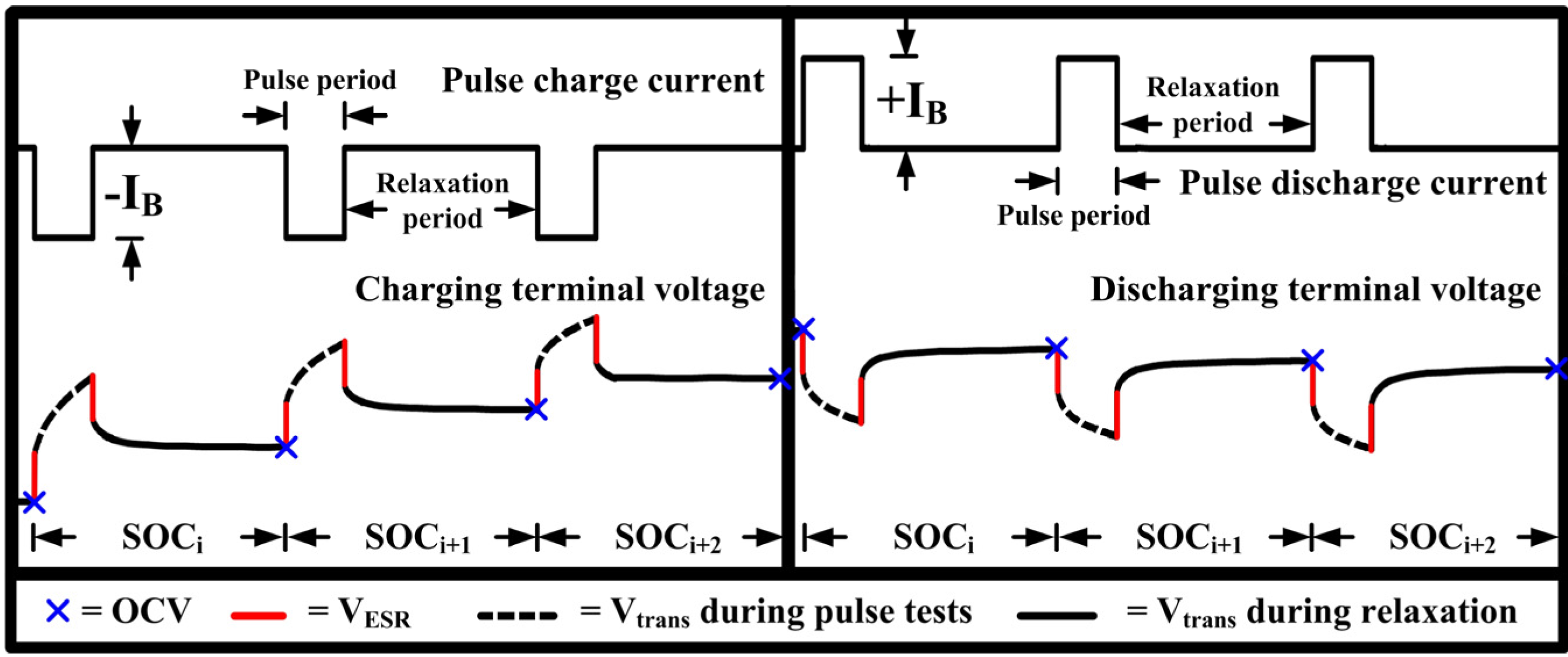
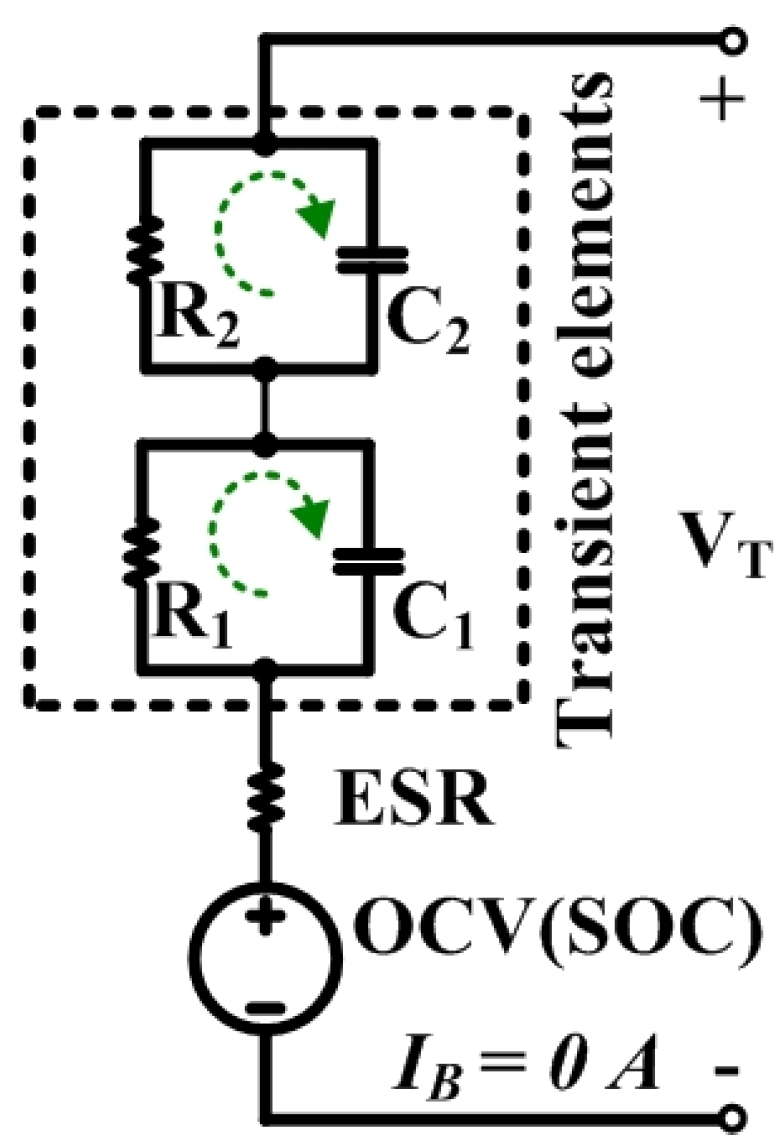
2. Open Circuit Voltage Determination for Li-Ion Battery

The OCV in the electrical equivalent circuit model of the LIB shown in Figure 1 is extracted as a measured voltage at the battery terminals (VT) after resting to recover the battery close to its equilibrium state [6]. In Figure 2, the OCVs are determined as a terminal voltage after relaxing from the applied short pulse currents both on the discharge and charge operations. This method is called the OCV pulse test method based on the galvanostatic intermittent titration technique [17].
After a long resting of at least 60 min for our tested LMO to make sure that the cell voltage is constant and close to its equilibrium (The experimental details are shown in Section 4.2), the battery current (IB) and voltages across the effective series resistance (VESR) and transient elements (Vtrans) become zero. Then, the VT in Equation (1) can be assumed for the OCV:
V T = O C V V ESR V trans
E S R = V E S R / I B
From Figure 1, the other parameters will be ignored such as: (1) effective series resistance (ESR), which reflects the resistances of the connecting wires, electrodes, separator and electrolyte; and (2) transient elements, which reflect the charge-transfer resistance (R1), double-layer capacitance (C1), diffusion process resistance (R2), and its capacitance (C2) because they have no effect on the OCV. Usually, the OCV is illustrated as a function of the SOC in order to compare between the different testing conditions during the studies. The SOC calculation based on the coulomb counting method, is shown in Equation (3), and is calculated from the actual capacity of the battery. In addition, the SOCs between 0% and 100% are set within the operating voltage ranges of the cell between 3.0 V and 4.2 V, respectively:
S O C ( t ) = S O C 0 t 0 t cut off I B 3600 × Q B d t
where IB is the battery current, which is positive for discharging and negative for charging; QB is an accumulated capacity of the battery in Ah; and SOC0 is an initial value of the SOC.

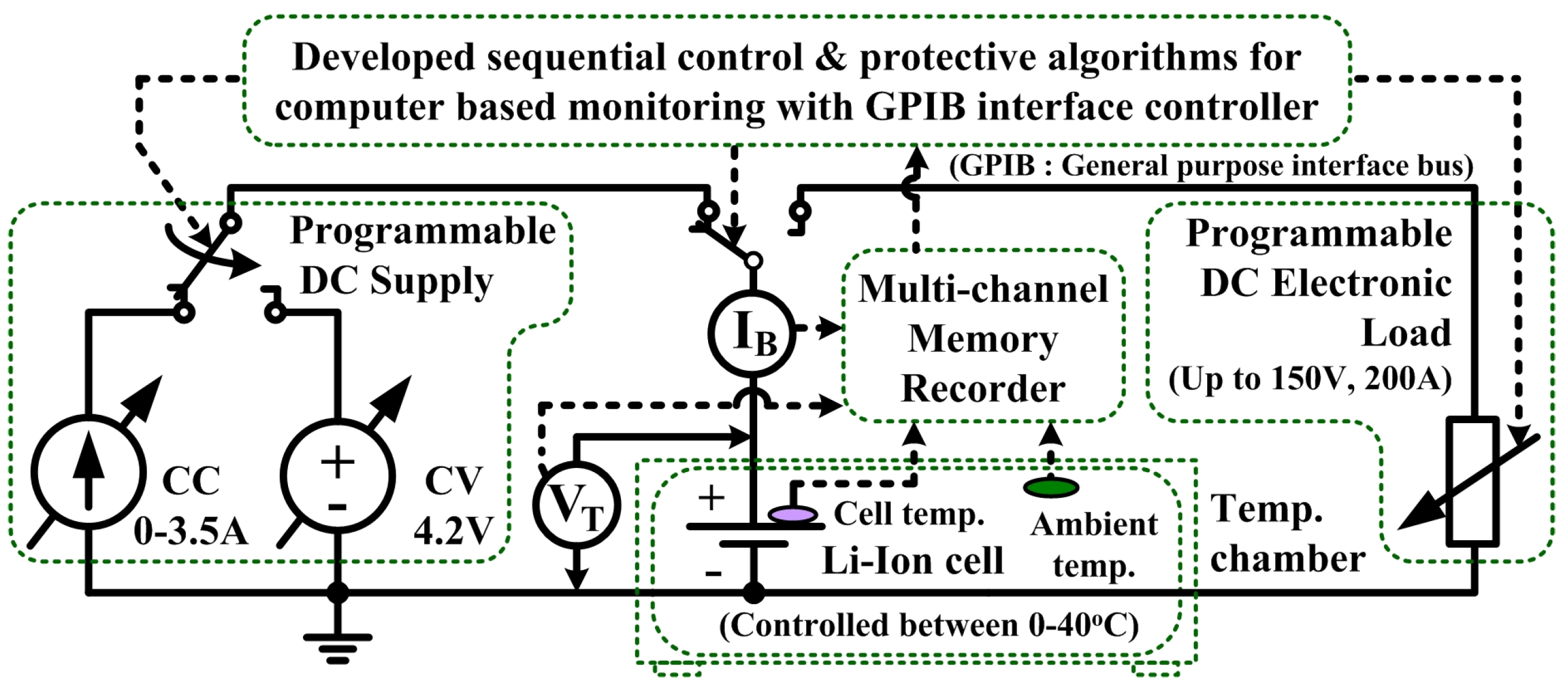
3. Open Circuit Voltage Characterization System

The OCV characteristics are different and unique depending on their active electrode materials for the different types of the LIB [18]. It takes a significant amount of time to characterize the OCV. In order to identify the precise OCV characteristics based on the sequential pulse tests, a reliable LIB test system is needed. A manganese-type single cell from NEC-Tokin (Chiyoda, Tokyo, Japan) was used in this study. A cell specification is shown in Table 1. In this section, the developed test system with computer-based controlling is introduced for the OCV characterization, as illustrated in Figure 3. The test system is developed in the Labview environment (Japan National Instrument Inc., Minato, Tokyo, Japan) for controlling the instruments to charge and discharge the LIB via a general-purpose interface bus (GPIB) controller.
The test system should operate automatically following the sequential programs with a safety for the test parameters such as C-rates, pulse durations, rest times, pulse cycles and protective setting values for operations without malfunctions for any LIB types. The system also records the related parameters and status of the LIB during the testing such as battery voltage, current, left-cycle, piecewise pulse duration, rest duration, date, time, status of testing, and the alarm message in case of reaching the protection limits via the display monitor. The sampling interval is set to 10 ms/sampling, which is sufficient to observe the pulse transient response for the precise OCV characterization.

4. Discussion on the Factors for Accurate Open Circuit Voltage Determination

In this section, the effects of the step-sizes and resting periods of the cell during the pulse tests and current amplitudes during the pulse and continuous charge-discharge tests are experimentally investigated and discussed for the suitability of testing conditions to provide an accurate OCV characterization by using the developed test system in Section 3.

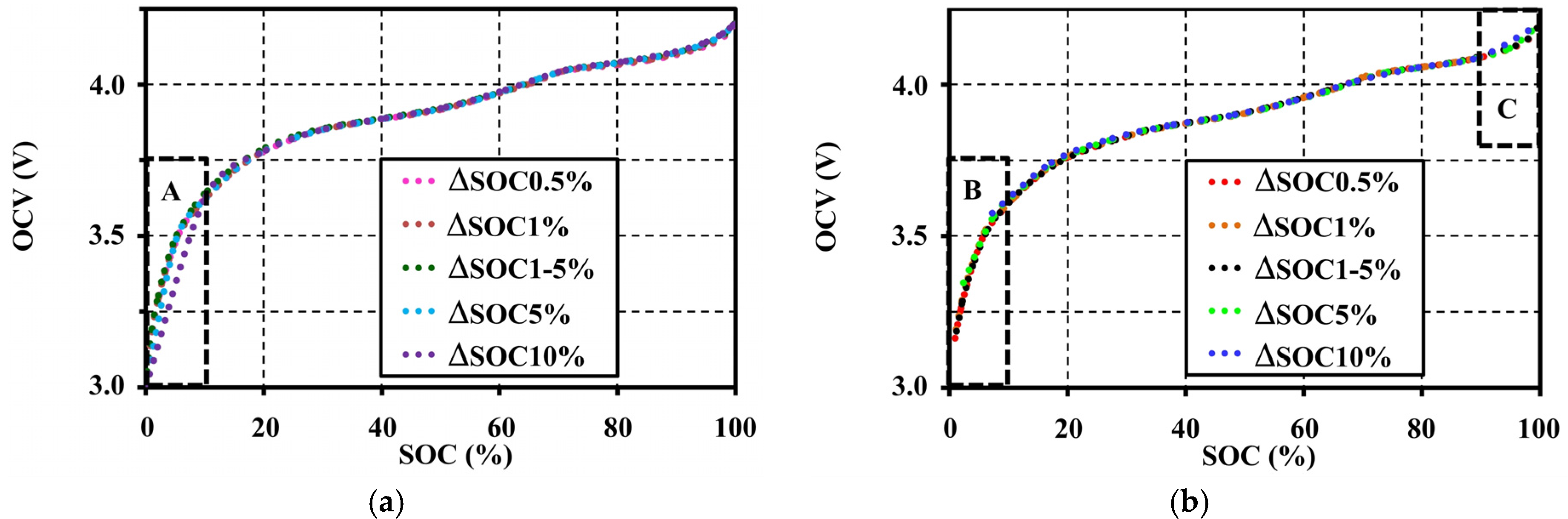
4.1. Effects of Step-Sizes during Pulse Tests on the Open Circuit Voltage Characteristic

For this study, OCVs were extracted from the pulse tests at different step-sizes. Step-sizes (ΔSOC) are set at 0.5%, 1%, 5%, and 10% using the same condition (at 1C-rate 20°C with 10 min resting) separately for each pulse charge and discharge. ΔSOC 0.5%, 1%, 5%, and 10%, which means the setting of the step-size of the pulse tests was equally at 0.5%, 1%, 5%, and 10%, respectively, between 0% and 100% of the SOC range. ΔSOC 1%–5% on the other hand means the variable step-size of the pulse tests has a 1% step for the 0%–10% and the 90%–100% SOC ranges, which are in non-linear operating regions of the battery, and a 5% step for the 10%–90% SOC range, which is in the linear region. The tests were performed within the limits of the rated voltage between 3 V and 4.2 V. The effect of step-sizes of pulse tests to the OCV characteristic are shown in Figure 4. ΔSOC 1% and 0.5% give the same OCV characteristic for all SOC ranges. ΔSOC 5% also gives the same OCV result for the SOC range between 10% and 90%. However, it gives an inconsistent OCV for the SOC ranges below 10% and above 90% (non-linear regions). During these non-linear regions (windows A and C in Figure 4), the larger step-size prominently affects to the OCV pattern. Moreover, wide steps also cause the incomplete OCV measurement in a low SOC range (0%–10%), as illustrated by the blue and green dots in Window B of Figure 4b. These incomplete and incorrect OCVs resulted from a long pulse release time that caused the inadequate resolution for OCV extraction.
In summary, the 1% step-size is sufficient for precise OCV characterization for SOC ranges below 10% and above 90%, and the 5% step-size for the 10%–90% SOC range. Figure 4 also shows the extracted OCVs for a step-size at ΔSOC 1%–5%. ΔSOC 1%–5% also gives a satisfactory OCV characteristic. Therefore, the ΔSOC 1%–5% should be chosen to apply for all of our tests.

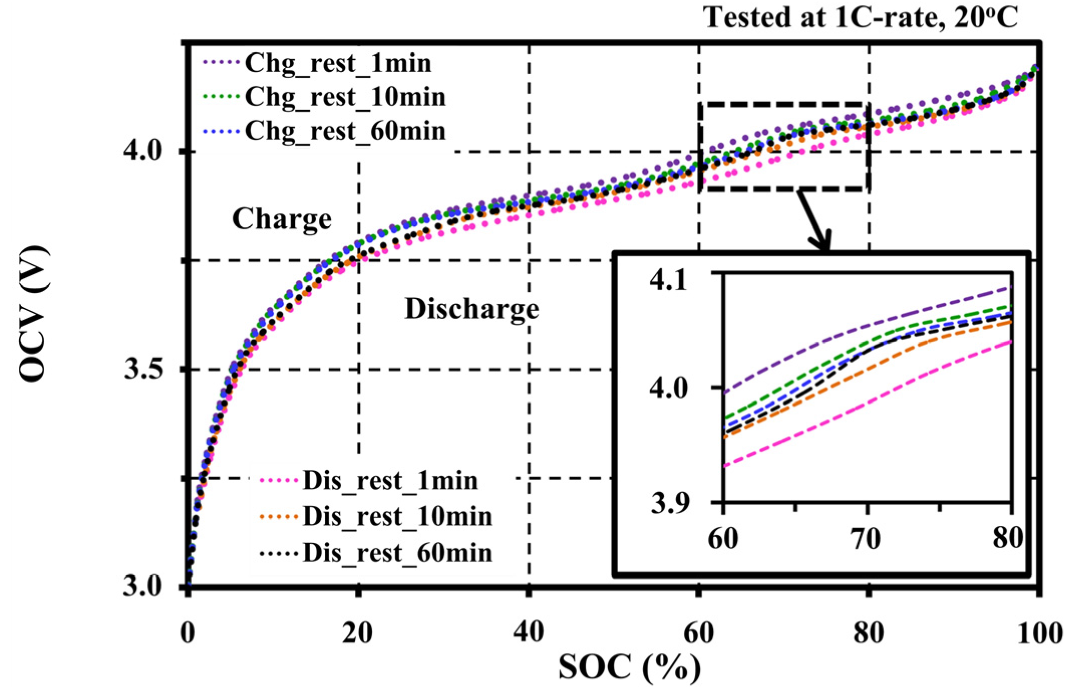
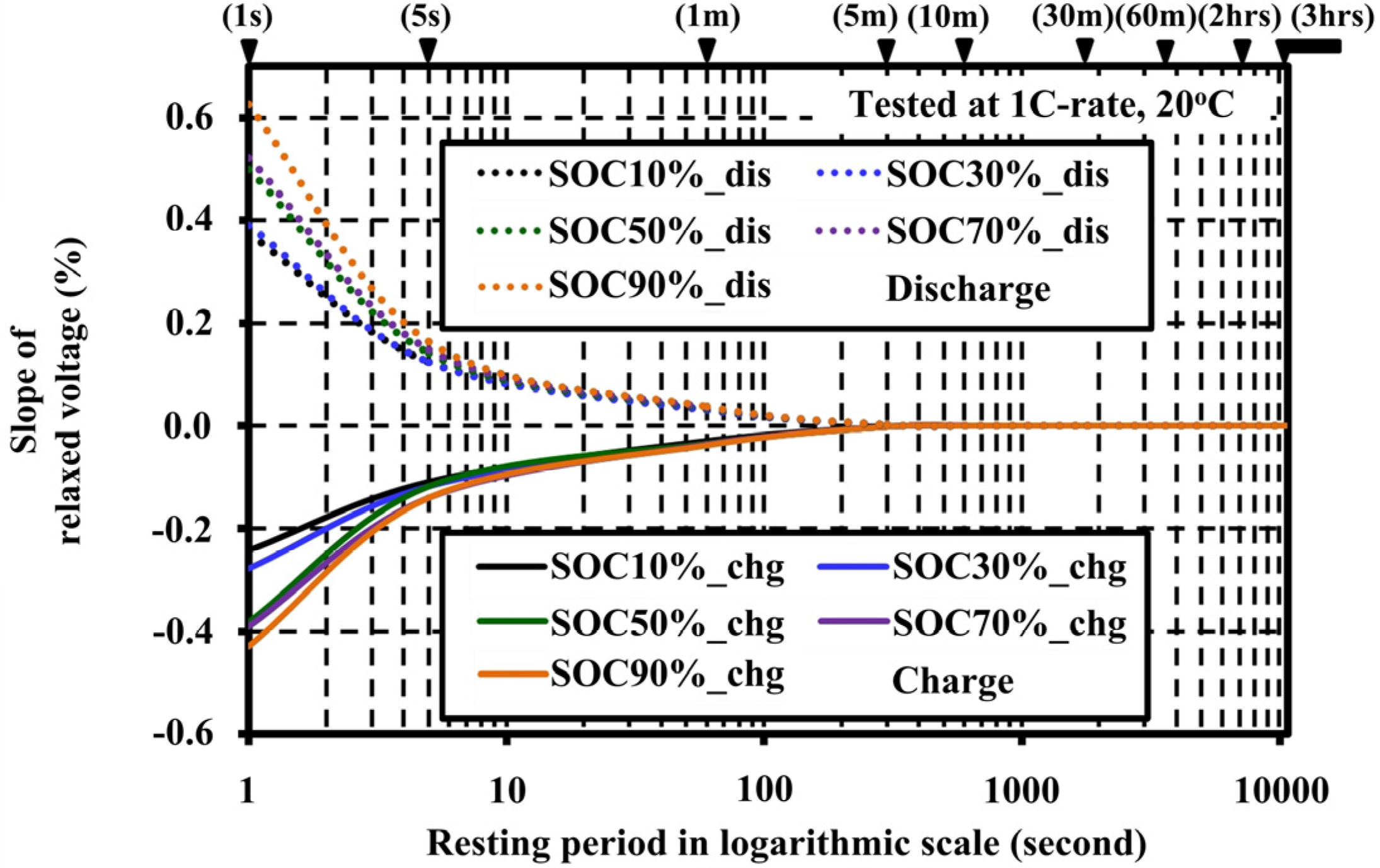
4.2. Effects of Resting Periods during Pulse Tests on the Open Circuit Voltage Characteristic

In order to study the effects of resting periods of the cell during the pulse tests, the voltage of the cell was measured for each SOC step in terms of the slope percentage of the relaxed voltage (%Sloperv). The %Sloperv can be calculated with Equation (4). The tests were performed at different resting periods from 1 s to 3 h to identify a suitable relaxation period for the accurate OCV determination:
% S l o p e rv = 100 × ( V S O C i V S O C i 1 ) ( t S O C i t S O C i 1 )
where V S O C i and t S O C i are the voltage and time at the end of the relaxation state for each SOC step, V S O C i 1 and t S O C i 1 are the voltage and time at the starting of the relaxation state for each SOC step.
The slopes of the relaxed voltage versus the resting periods illustrated in Figure 5 show that the variation of voltage decayed down near zero after 1 min of resting. The slopes for all SOCs decayed down to zero at 60 min of resting. Therefore, the resting period should be evaluated between 1 min and 60 min to observe the influence on the extracted OCV.
Figure 6 shows the effect of different resting periods to the extracted OCV under the same testing condition (at 1C-rate 20 °C with ΔSOC 1%–5%). The low resting period gives a bloated OCV between 60% and 80% SOCs, and cannot reflect the actual OCV characteristic both on the charge and discharge operations. From the experiments, a recommended resting period for accurate OCV for this cell type is at 60 min to ensure that the cell has reached its equilibrium. However, it can be reduced to 30 min or 10 min for a fast OCV approximation.

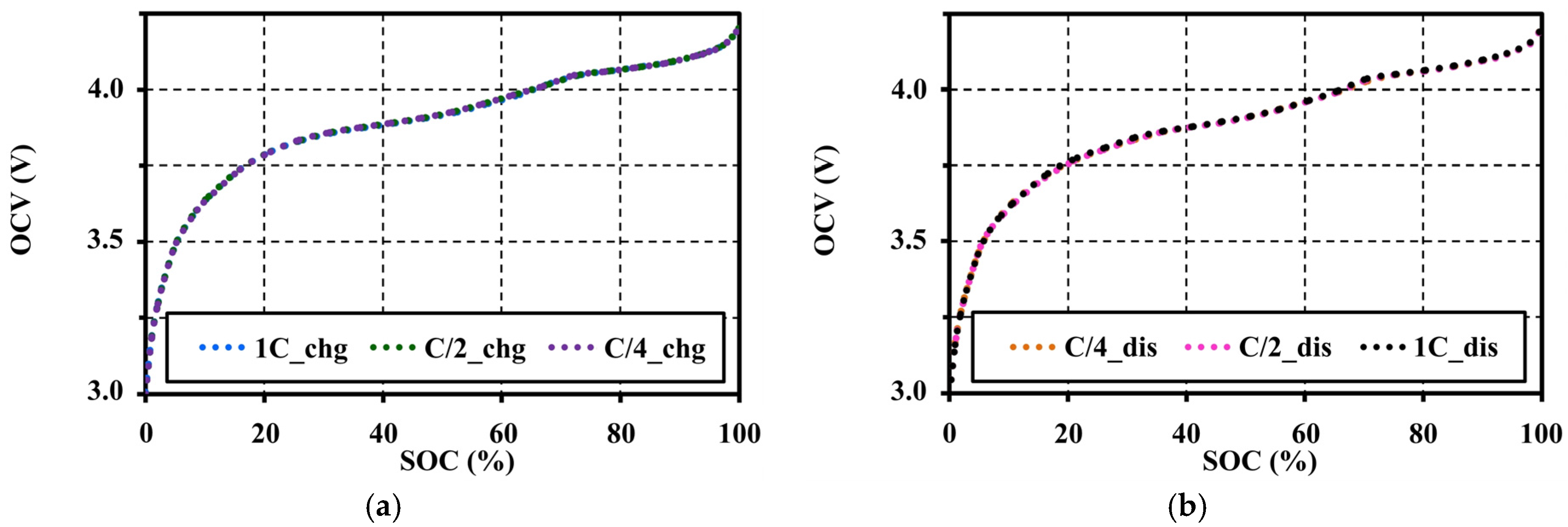
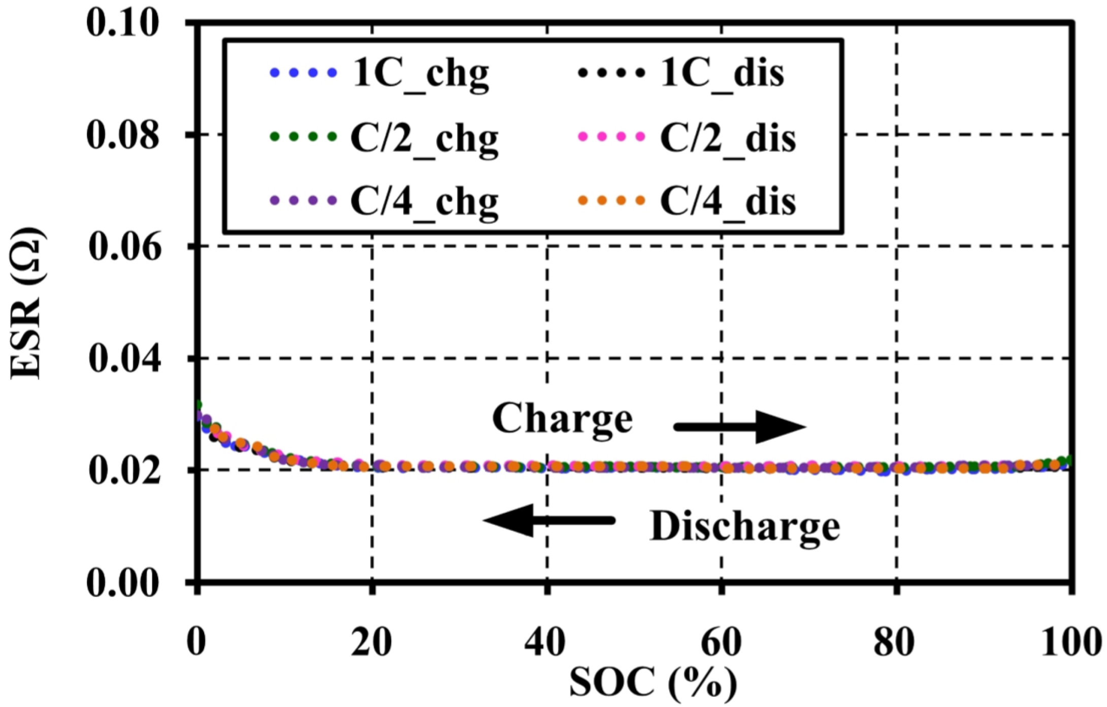
4.3. Effects of Current Amplitudes during Pulse Tests on the Open Circuit Voltage Characteristic

In order to investigate the effects of current amplitudes (C-rates) on the OCV, the pulse charge and discharge tests were performed under the same testing condition (at 20 °C with ΔSOC 1%–5% and 60 min resting for each pulse). The OCVs were extracted for different C-rates between C/4 and 1C. The effects of the pulse C-rates on the OCV are shown in Figure 7.
The extracted OCV results under an adequate relaxing period show that the voltage patterns for the different C-rates correspond to both charge and discharge tests. In addition, the ESRs are also extracted from an instantaneous response of the pulse charge and discharge tests. The ESRs are almost constant for the SOC and C-rates as illustrated in Figure 8. It can be concluded that the pulse current amplitudes have no effect on the OCV and ESR characteristics under a constant temperature and the same resting period. Figure 9 shows the OCV comparison between charge (chg) and discharge (dis) under the different C-rates. During the charge and discharge, a small hysteresis occurs in the range of 5%–40% SOC, which is magnified in Figure 10.
Figure 10 shows that the C-rates of the pulse tests also have no effect on the hysteresis character. The hysteresis, which results from mechanical stress, thermo-dynamical entropic effects and microscopic distortions within the active electrode material during Li-intercalation, is unique for each cell material [19]. This cell type illustrates a narrow hysteresis property between the charge and discharge.
The difference in OCVOCV) for the charge and discharge to the averaged values is shown in Figure 11. The maximum and minimum voltage gaps of the averaged OCV that occurred at 25% SOC are only ±14.368 mV, or ±0.379% of its average value.

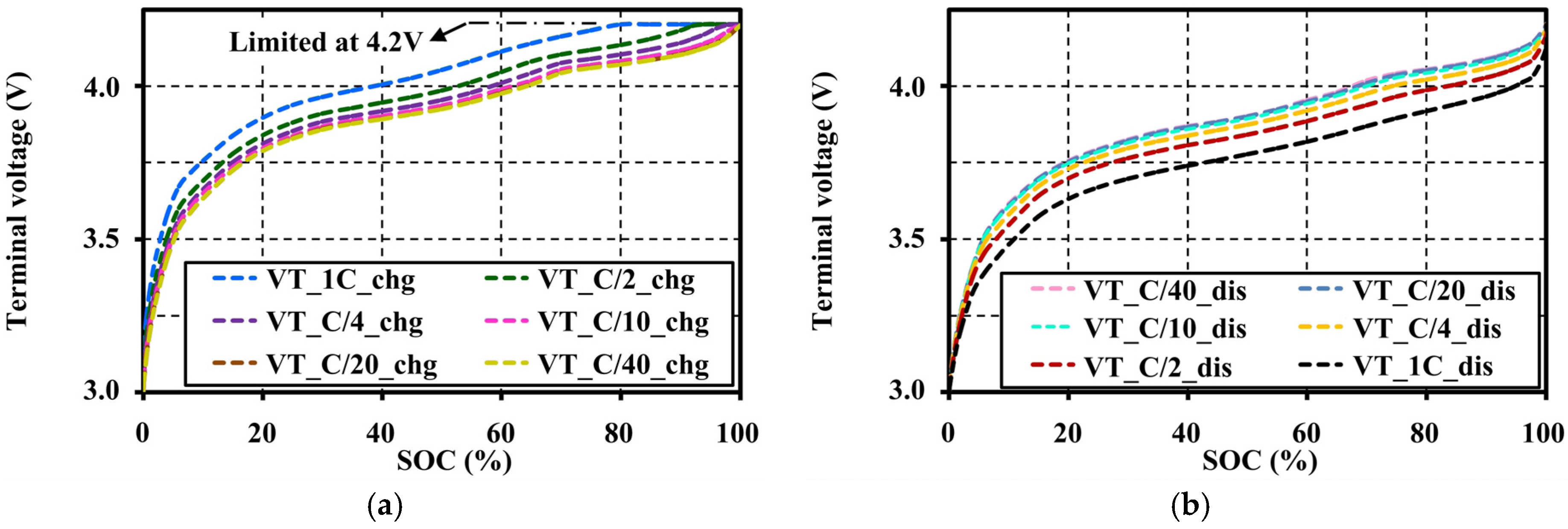
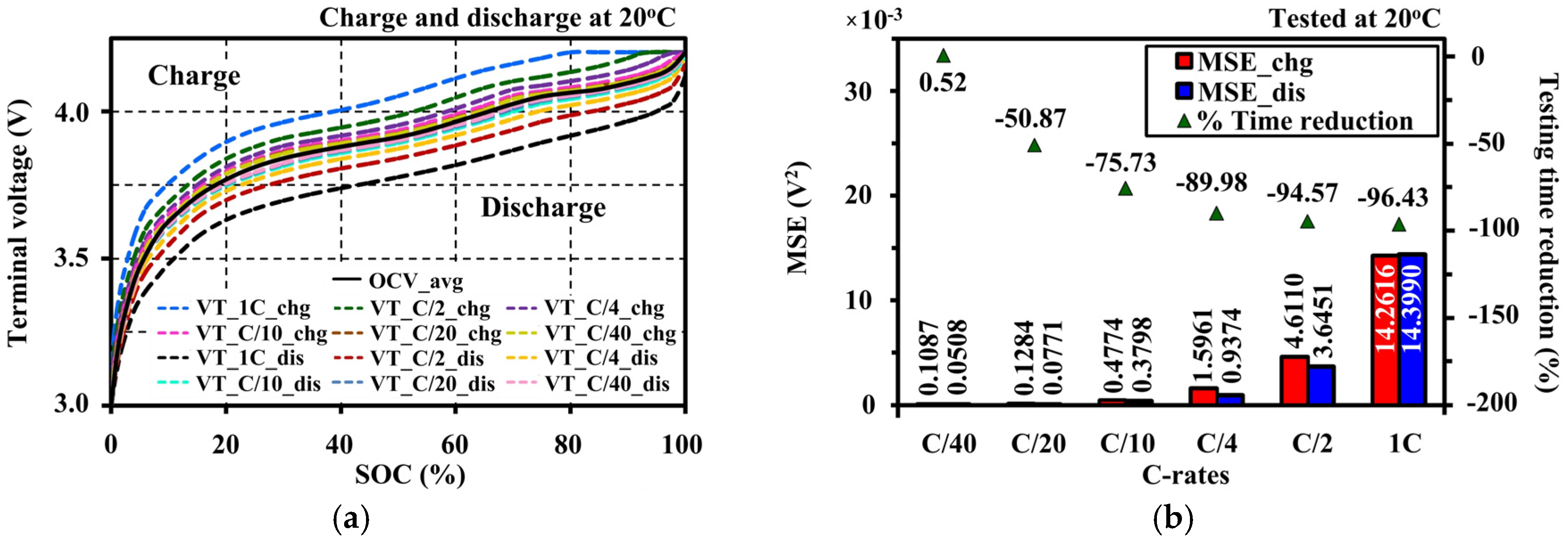
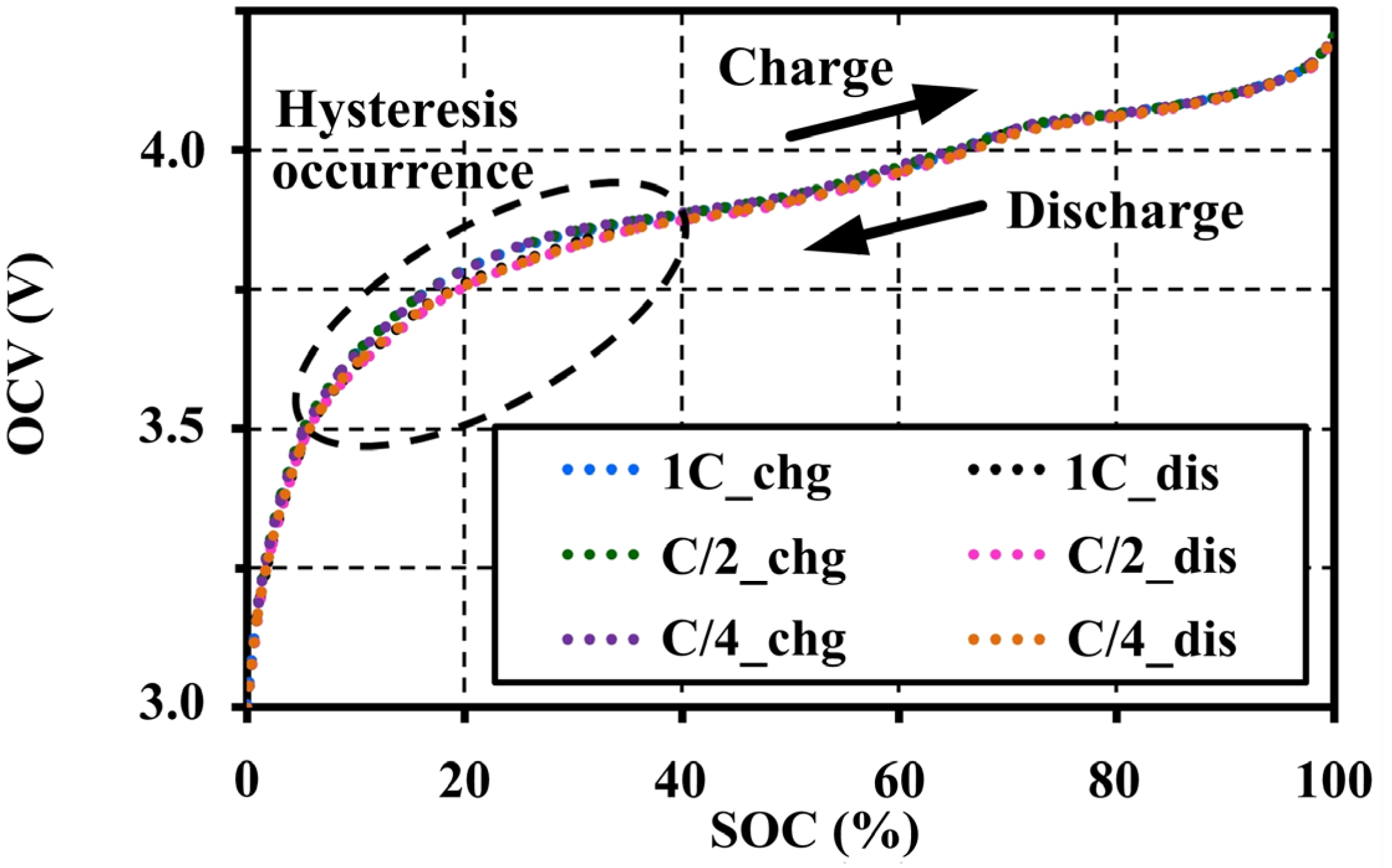
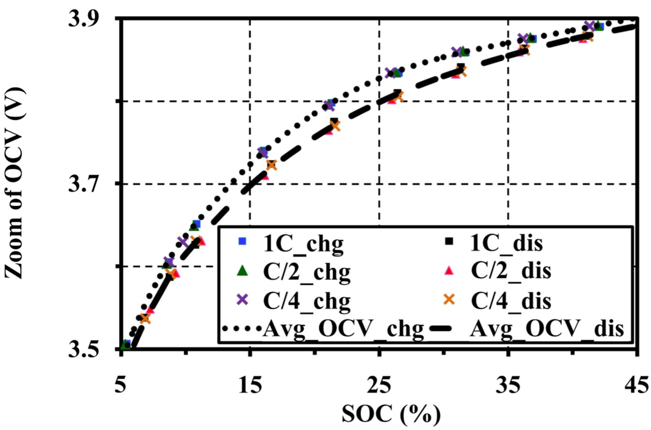
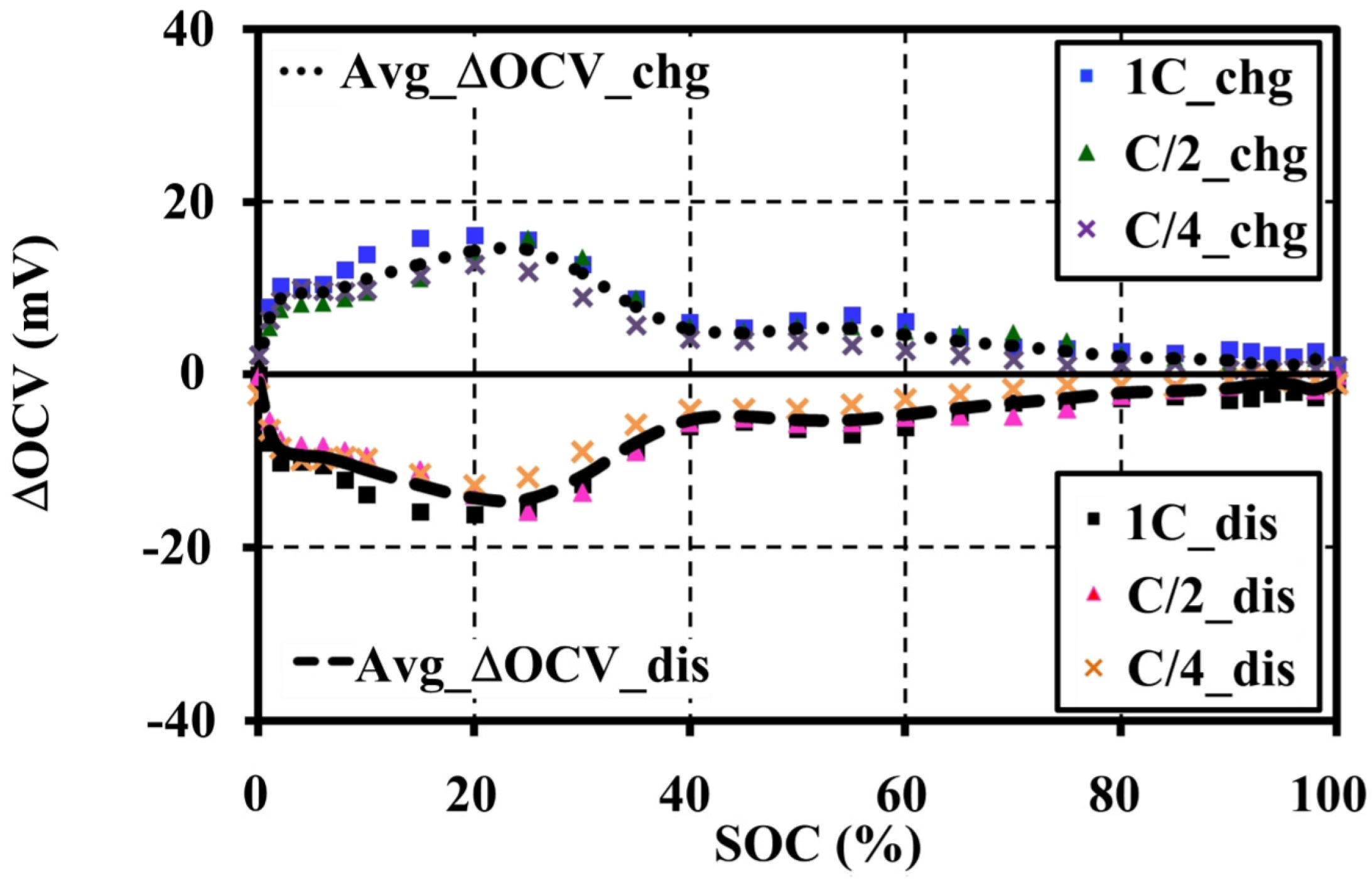
4.4. Effects of Current Amplitudes during Continuous Charge and Discharge Tests on the Open Circuit Voltage Approximation

In this study, continuous charge and discharge tests were performed with different current amplitudes (C-rates) between C/40 and 1C within the operating voltage ranges of the cell in order to study the influence of C-rates on the terminal voltage characteristics (VTs), and then to investigate the relationship of VTs on the OCV approximation. The effects of different C-rates on the terminal voltage characteristic are shown in Figure 12. The C-rates lower than C/20 do not obviously show the characteristic difference. However, the lower C-rates clearly illustrate the appearance of curly trends on both charge and discharge voltage profiles, especially between 60% and 80% SOCs as shown in Figure 12a,b, respectively.
Figure 13 shows the relationship between the average OCV and charge/discharge terminal voltages under different C-rates. Figure 13a shows that the VTs for low C-rates precisely illustrate the OCV. The polarization voltage gaps between charge and discharge VTs at the same C-rate can be reduced for the low C-rate. The polarization mechanism of the VTs is directly influenced by the C-rate. The cell operating at the higher current presents more polarization effects. As aforementioned in Section 4.3, the ESRs and OCVs for each charging and discharging do not change for the C-rates. Therefore, the voltage drops across the ESR depend on the current, resulting in the increment of the terminal voltage. It can be recommended that the OCV characteristic can be approximated by measuring a terminal voltage at the low testing current.
Figure 13b shows the mean of the squared residuals of the errors (MSEC-rate) between the OCV and terminal voltage for each C-rate of Figure 13a, and shows a testing time reduction for the OCV approximation under different rates of continuous testing current.
The MSEC-rate can be determined separately for charge and discharge by using Equation (5):
M S E C rate = 1 n S O C i = 1 S O C n ( V T S O C i O C V ( S O C i ) ) 2
where V T S O C i is a measured terminal voltage at SOCi for a continuous test, OCV(SOC)i is an open circuit voltage obtained by OCV averaging at the different C-rates as a function of SOCi for a sampling number n separately for charge and discharge.
A recommended continuous testing current rate for the OCV approximation is C/20 because it can save time for charge and discharge tests from 82.86 h to 40.71 h (or 50.87%) with low MSEs of only 0.1284 × 10⁻³ V2 and 0.0771 × 10⁻³ V2 for the charge and discharge, respectively. Moreover, it is also faster than the C/40 rate by 52.39% with the difference of MSEs of only 0.0197 × 10⁻³ V2 and 0.0263 × 10⁻³ V2 for the charge and discharge, respectively.

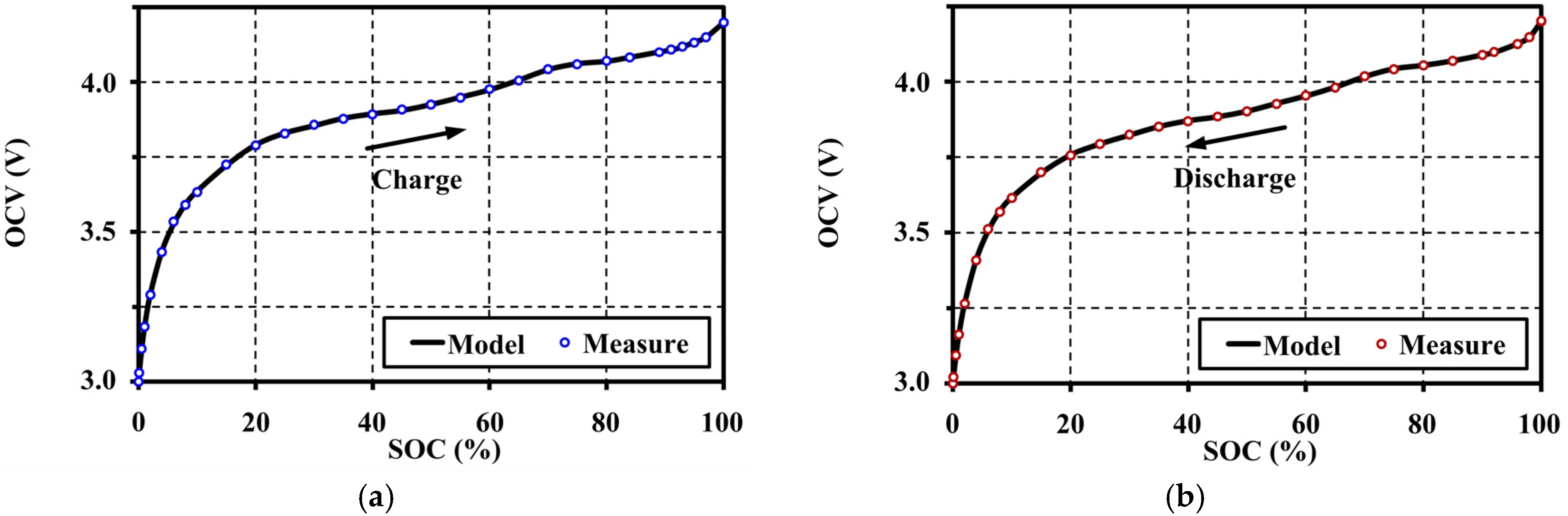
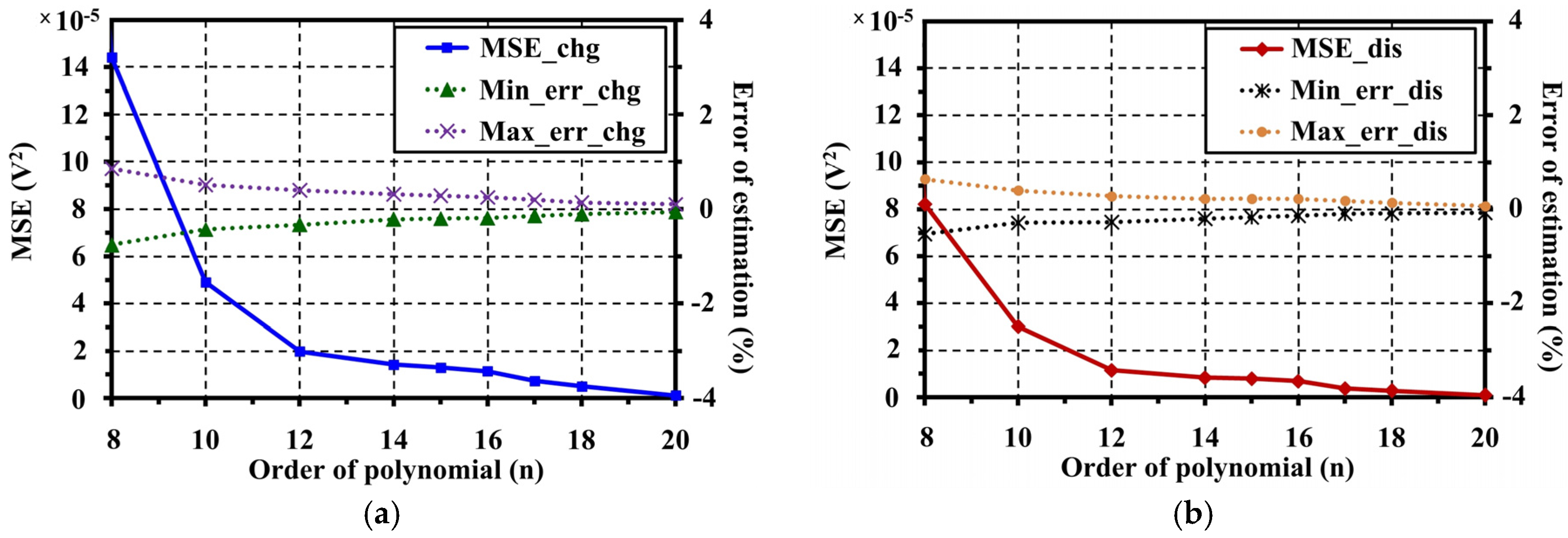
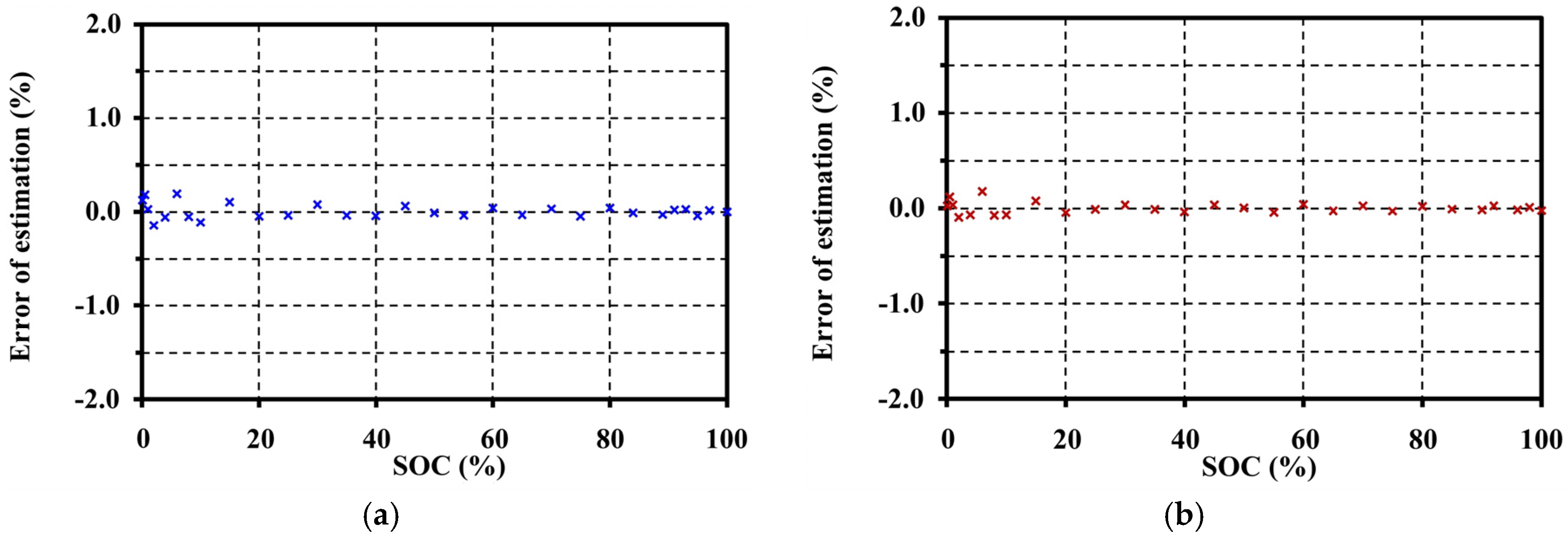
5. Open Circuit Voltage Modeling

A model of the OCV characteristic in LIBs is essential for the BMS in order to estimate the state variables during operations. Many OCV models of the batteries have been proposed [2,20]. They are related to the internal chemical variation of the batteries to fit with the tested results, depending on the purpose of the study and their applications. The factors that affected the OCV pattern are studied in Section 4, and the step-size of the pulse test and resting period are adjusted to obtain the accurate OCV. At the same time, we also found that the rates of the testing current (C-rates) have no effect on the OCV. The representative of a precise OCV from the experiments under these conditions can be obtained by averaging the OCV under C-rates separately for the charge and discharge. Therefore, a simplified OCV model for the LMO can only be developed as a function of SOC, and then it is validated with the experimental OCV data. The empirical high-order polynomial is used for implementing the model with a real-time calculation in the BMS application, as shown in Equation (6):
O C V ( S O C ) = j = 0 n ( k j S O C j )
The coefficients (kj) in Equation (6) are determined with MATLAB (MathWorks Japan, Nagoya, Aichi, Japan) for the experimental SOC and OCV data from the previous section by using a non-linear least square estimation technique. The objective function is given, as in Equation (7):
min k f ( k , S O C ) O C V 2 = min k i = 1 m [ f ( k , S O C i ) O C V i ] 2
where k is the SOC coefficient to be optimized; j is the degree of polynomial; n is the highest-order of polynomial; and m is the length of SOC and OCV data.
From Equation (6), the highest-order (n) for smooth fitting of the OCV analytic function for this LMO is 17th for both charging and discharging. For this order, the MSEs are less than the maximum criteria (≤1 × 10⁻⁵ V2) that is precise enough for fitting the OCV model. The extracted OCV models are shown by the solid line in Figure 14.
The fitting results from Figure 14 show that the proposed OCV model can illustrate the voltage characteristics correctly along the SOC range on both charge and discharge operations separately by the hysteresis phenomena. A comparison of the MSEs and errors of estimation at different polynomial orders for OCV model fitting is shown in Figure 15. The optimum SOC coefficients of the OCV model for charge and discharge are shown in Table 2.
The errors of OCV model are evaluated in Figure 16 by MSE). The MSEs for charging and discharging are only 0.7414 × 10⁻⁵ V2 and 0.3848 × 10⁻⁵ V2, respectively.
The minimum, maximum, and average values of the estimation error for charge are −4.7265 × 10⁻³ V, 6.9326 × 10⁻³ V, and 7.8056 × 10⁻⁸ V (or −0.1437%, 0.1961%, and 0.00008%), respectively, while the minimum, maximum, and average values of the estimation error for discharge are −3.0394 × 10⁻³ V, 6.3308 × 10⁻³ V, and 1.1389 × 10⁻⁷ V (or −0.0931%, 0.1802%, and 0.00004%), respectively.

6. Conclusions

This article studied the factors for the accurate OCV characterization of manganese-type Li-ion batteries for the BMS application. The charge and discharge test system is developed for use with the OCV pulse test method. An automatic battery test system is proposed for OCV characterization. From this study, we found that the accurate OCV for LMO can be obtained with a small step-size pulse of 1% for the non-linear regions below 10% and above 90% SOCs. However, the step-size can be increased up to 5% in the range of 10%–90% SOC for faster extraction with a small error. The short resting period of the pulse test directly affects the error of the OCV pattern. A recommended resting period for accurate OCV on this battery type is 60 min. The testing current rates (C-rate) of the pulse tests have no effect to the OCV and ESR patterns. This studied cell illustrates a small hysteresis effect between charge and discharge operations with the maximum voltage gap of only 28.736 mV. For the relationship of VTs to OCV, the measuring of terminal voltage of the cell under the low C-rate of C/20 can illustrate the approximate OCV characteristic with acceptable MSE value by using only half the time for testing. This article also developed an OCV model for the LMO as a polynomial function of the SOC to simplify the numerical calculations using in the BMS application. The model is validated with the OCV experimental results, which has the MSE values of only 0.7414 × 10⁻⁵ V2 and 0.3848 × 10⁻⁵ V2, and the maximum errors are only 0.1961% and 0.1802% for charging and discharging, respectively.
However, the OCV characterization and modeling, depending on the temperatures and operating cycles, are still challenging in practical applications. Studies on the changes of the OCV characteristics and their behaviors with the consideration of life cycles and temperatures should be investigated next, and are our next steps in the near future.

Acknowledgments

The authors thank the anonymous reviewers for providing useful suggestions and valuable comments that resulted in the improved quality of the paper.

Author Contributions

Natthawuth Somakettarin and Tsuyoshi Funaki conceived and designed the experiments; Natthawuth Somakettarin performed the experiments and analyzed the data; Natthawuth Somakettarin and Tsuyoshi Funaki wrote the paper.

Conflicts of Interest

The authors declare no conflict of interest.

References

  1. Chen, M.; Rincon-Mora, G.A. Accurate electrical battery model capable of predicting runtime and I-V performance. IEEE Trans. Energy Convers. 2006, 21, 504–511. [Google Scholar] [CrossRef]
  2. Pattipati, B.; Balasingam, B.; Avvari, G.V.; Pattipati, K.R.; Bar-Shalom, Y. Open circuit voltage characterization of lithium-ion batteries. J. Power Sources 2014, 269, 317–333. [Google Scholar] [CrossRef]
  3. Roscher, M.A.; Sauer, D.U. Dynamic electric behavior and open-circuit-voltage modeling of LiFePO4-based lithium ion secondary batteries. J. Power Sources 2011, 196, 331–336. [Google Scholar] [CrossRef]
  4. Lee, S.; Kim, J.; Lee, J.; Cho, B.H. State-of-charge and capacity estimation of lithium-ion battery using a new open-circuit voltage versus state-of-charge. J. Power Sources 2008, 185, 1367–1373. [Google Scholar] [CrossRef]
  5. Roscher, M.A.; Assfalg, J.; Bohlen, O.S. Detection of utilizable capacity deterioration in battery systems. IEEE Trans. Veh. Technol. 2011, 60, 98–103. [Google Scholar] [CrossRef]
  6. Petzl, M.; Danzer, M.A. Advancements in OCV measurement and analysis for lithium-ion batteries. IEEE Trans. Energy Convers. 2013, 28, 675–681. [Google Scholar] [CrossRef]
  7. Codeca, F.; Savaresi, S.M.; Rizzoni, G. On Battery State of Charge Estimation: A New Mixed Algorithm. In Proceedings of the 17th IEEE International Conference on Control Applications, Part of 2008 IEEE Multi-conference on Systems and Control, San Antonio, TX, USA, 3–5 September 2008; pp. 102–107.
  8. Pattipati, B.; Sankavaram, C.; Pattipati, K.R. System identification and estimation framework for pivotal automotive BMS characteristics. IEEE Trans. Syst. Man Cybern.-Part C Appl. Rev. 2011, 41, 869–884. [Google Scholar] [CrossRef]
  9. Somakettarin, N.; Funaki, T. An Experimental Study on Modeling of Transient Response and Parameters Identification for Mn-Type Li-Ion Battery with Temperature Dependency. In Proceedings of the International Conference on Renewable Energy Research and Application (ICRERA), Milwaukee, WI, USA, 19–22 October 2014; pp. 804–809.
  10. Julien, C.M.; Mauger, A.; Zaghib, K.; Groult, H. Comparative issues of cathode materials for Li-ion batteries. Inorganics 2014, 2, 132–154. [Google Scholar] [CrossRef]
  11. Kim, D.K.; Muralidharan, P.; Lee, H.W.; Ruffo, R.; Yang, Y.; Chan, C.K.; Peng, H.; Huggins, R.A.; Cui, Y. Spinel LiMn2O4 nanorods as Lithium ion battery cathodes. Nano Lett. Am. Chem. Soc. 2008, 8, 3948–3952. [Google Scholar] [CrossRef] [PubMed]
  12. Patil, A.; Patil, V.; Shin, D.W.; Choi, J.W.; Paik, D.S.; Yoon, S.J. Review issue and challenges facing rechargeable thin film lithium batteries. Mater. Res. Bull. 2008, 43, 1913–1942. [Google Scholar] [CrossRef]
  13. Piao, T.; Parka, S.M.; Dohb, C.H.; Moon, S.I. Intercalation of Li-ion into graphite electrodes studied by AC impedance measurements. J. Electrochem. Soc. 1999, 146, 2794–2798. [Google Scholar] [CrossRef]
  14. Wang, J.; Purewal, J.; Liu, P.; Garner, J.H.; Soukazian, S.; Sherman, E.; Sorenson, A.; Vu, L.; Tataria, H.; Verbrugge, M.W. Degradation of lithium ion batteries employing graphite negatives and nickel-cobalt-manganese oxide + spinel manganese oxide positives: Part 1, aging mechanisms and life estimation. J. Power Sources 2014, 269, 937–948. [Google Scholar] [CrossRef]
  15. Smith, A.J.; Burns, J.C.; Dahn, J.R. High-precision differential capacity analysis of LiMn2O4/graphite cells. Electrochem. Solid-State Lett. 2011, 14, A39–A41. [Google Scholar] [CrossRef]
  16. Safari, M.; Delacourt, C. Aging of a commercial graphite/LiFePO4 cell. J. Electrochem. 2011, 158, A1123–A1135. [Google Scholar] [CrossRef]
  17. Weppner, W.; Huggins, R.A. Determination of the kinetic parameters of mixed-conducting electrodes and application to the system Li3Sb. J. Electrochem. Soc. 1977, 124, 1569–1578. [Google Scholar] [CrossRef]
  18. Bisquert, J. Nanostructured Energy Devices: Equilibrium Concepts and Kinetics, 1st ed.; CRC Press, Taylor & Francis Group: Boca Raton, FL, USA, 2015; pp. 115–155. [Google Scholar]
  19. Roscher, M.A.; Bohlen, O.; Vetter, J. OCV hysteresis in Li-ion batteries including two-phase transition materials. Int. J. Electrochem. 2011, 2011. [Google Scholar] [CrossRef]
  20. Hu, X.; Li, S.; Peng, H.; Sun, F. Robustness analysis of state-of-charge estimation methods for two types of Li-ion batteries. J. Power Sources 2012, 217, 209–219. [Google Scholar] [CrossRef]
Figure 1. Electrical equivalent circuit model of the Li-ion battery (LIB).
Batteries 03 00008 g001
Figure 2. Current and voltage response for pulse tests to extract the open circuit voltage (OCV).
Batteries 03 00008 g002
Figure 3. A developed LIB test system with computer based control for OCV characterization.
Batteries 03 00008 g003
Figure 4. Effects of step-sizes during pulse tests on the OCV characteristic at 20 °C with 10 min resting: (a) under the charge test; and (b) under the discharge test.
Batteries 03 00008 g004
Figure 5. Slopes of the relaxed voltage versus the resting periods.
Batteries 03 00008 g005
Figure 6. Effects of resting periods on the OCV characteristic.
Batteries 03 00008 g006
Figure 7. Effects of pulse current amplitudes on the OCV characteristic at 20 °C with 60 min resting: (a) under the charge test; and (b) under the discharge test.
Batteries 03 00008 g007
Figure 8. Effects of pulse current amplitudes on the effective series resistance (ESR) characteristic tested at 20 °C with 60 min resting.
Batteries 03 00008 g008
Figure 9. Hysteresis occurrence on the OCV characteristics tested at 20 °C with 60 min resting.
Batteries 03 00008 g009
Figure 10. Zoom of the hysteresis occurrence tested at 20 °C with 60 min resting.
Batteries 03 00008 g010
Figure 11. ΔOCV for the averaged charge and discharge values tested at 20 °C with 60 min resting.
Batteries 03 00008 g011
Figure 12. Effects of current amplitudes on the terminal voltage characteristic at 20 °C: (a) under continuous charging; and (b) under continuous discharging.
Batteries 03 00008 g012
Figure 13. Terminal voltage relationship to the OCV approximation: (a) polarization differences of terminal voltages under different rates of continuous testing current on the average OCV; (b) mean of the squared residuals of the errors (MSE) and testing time reduction for OCV approximation under different rates of continuous testing current.
Batteries 03 00008 g013
Figure 14. OCV fitting results for the lithium manganese oxide (LMO) at 20 °C: (a) fitting result for charging; and (b) fitting result for discharging.
Batteries 03 00008 g014
Figure 15. Comparison results of MSEs and errors of estimation at different polynomial orders: (a) results for charge; and (b) results for discharge.
Batteries 03 00008 g015
Figure 16. Error evaluation for the OCV model validation for the LMO at 20 °C: (a) error of estimation for charge; and (b) error of estimation for discharge.
Batteries 03 00008 g016
Table 1. Cell specification.
DescriptionSpecificationDescriptionChargingDischarging
Electrode/typeSpinel single cellOperating voltage3.0 V4.2 V
PositiveManganese (LiMn2O4)Maximum current (C-rate)3.5 A (1C)20.0 A (5.7C)
NegativeLithiated graphite (LiC6)Operating temp.0–40 °C−10–50 °C
Rated capacity3.5 Ah (Typical)Cell dimension82 mm × 171 mm × 4.7 mm
Voltage3.8 V (Nominal)Weight100 g (Maximum)
Table 2. Optimum state of charge (SOC) coefficients of the OCV model for charge and discharge.
SOC CoefficientChargeDischargeSOC CoefficientChargeDischarge
k03.00373.0016k91.0595 × 10−98.4261 × 10⁻¹⁰
k12.3163 × 10−12.0082 × 10⁻¹k10−2.2638 × 10⁻¹¹−1.8003 × 10⁻¹¹
k2−6.5271 × 10⁻²−5.0440 × 10⁻²k113.6337 × 10−132.8847 × 10⁻¹³
k31.4950 × 10−21.1287 × 10⁻²k12−4.3564 × 10⁻¹⁵−3.4474 × 10⁻¹⁵
k4−2.3529 × 10⁻³−1.7962 × 10⁻³k133.8402 × 10−173.0257 × 10⁻¹⁷
k52.5025 × 10−41.9382 × 10⁻⁴k14−2.4147 × 10⁻¹⁹−1.8926 × 10⁻¹⁹
k6−1.8436 × 10⁻⁵−1.4444 × 10⁻⁵k151.0246 × 10−217.9827 × 10⁻²²
k79.6864 × 10−77.6498 × 10⁻⁷k16−2.6280 × 10⁻²⁴−2.0344 × 10⁻²⁴
k8−3.7174 × 10⁻⁸−2.9500 × 10⁻⁸k173.0772 × 10−272.3659 × 10⁻²⁷

