
Optimized Fuzzy-Cuckoo Controller for Active Power Control of Battery Energy Storage System, Photovoltaic, Fuel Cell and Wind Turbine in an Isolated Micro-Grid

Abstract
:1. Introduction
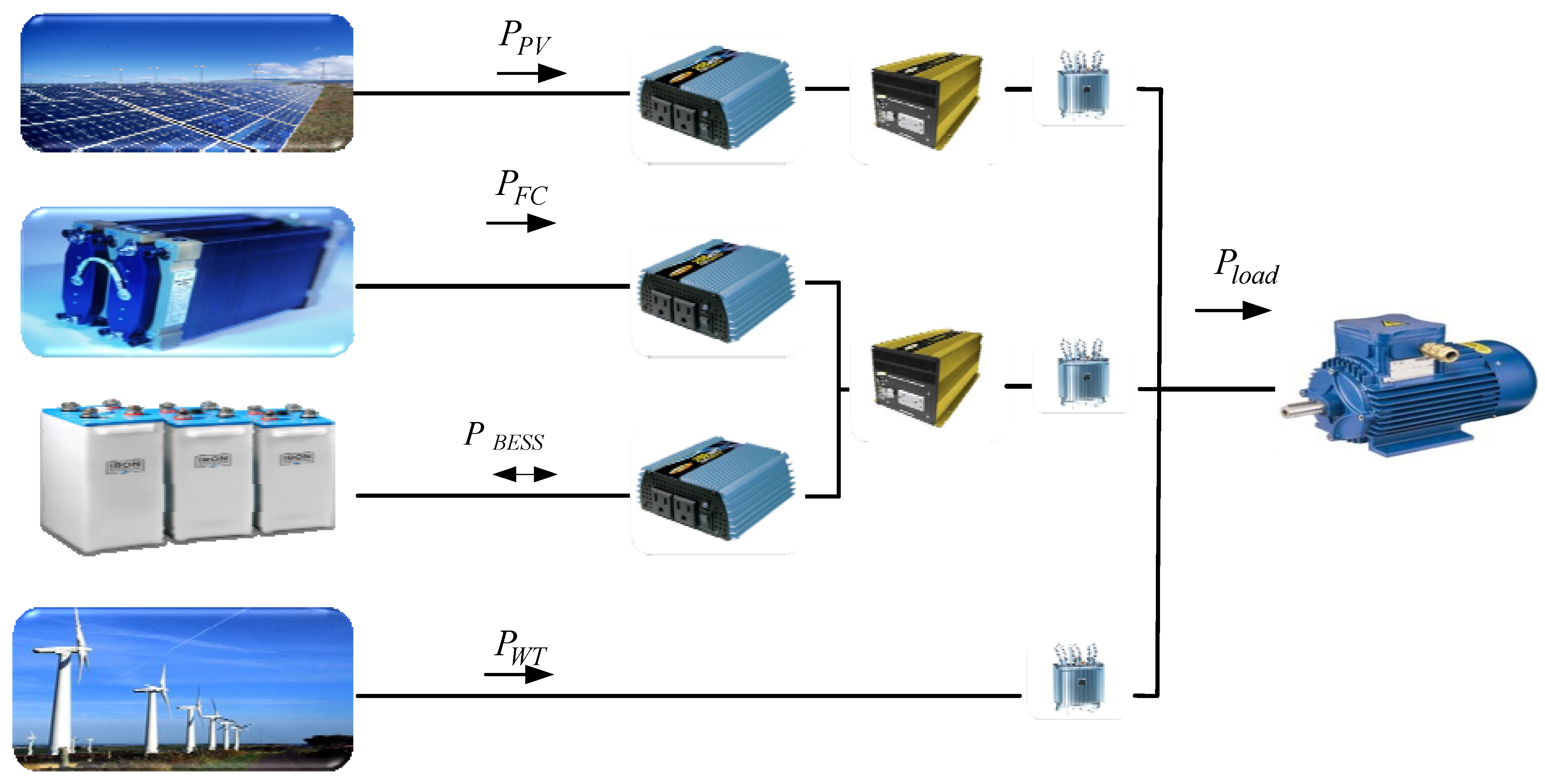
2. Modeling Isolated Micro-Grid
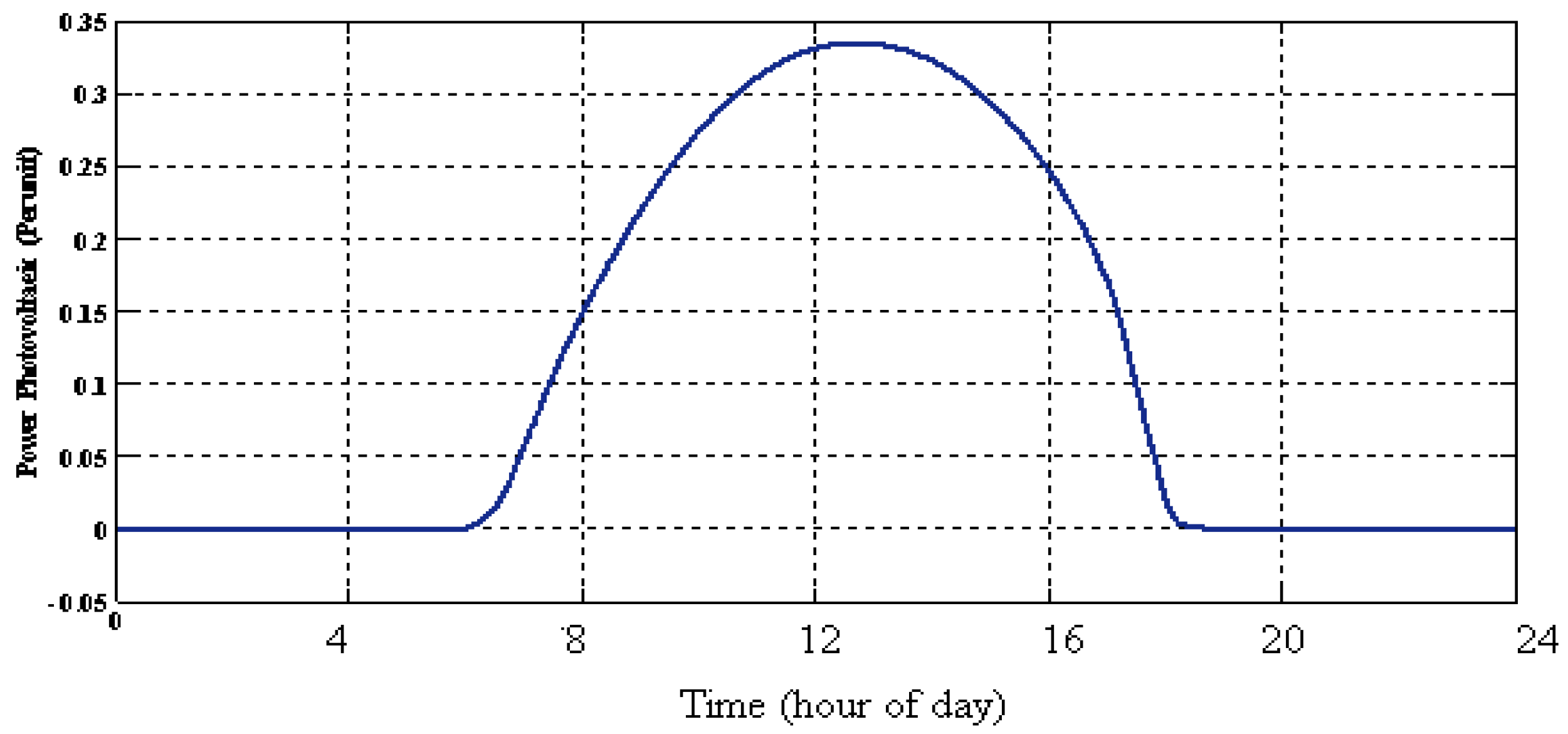
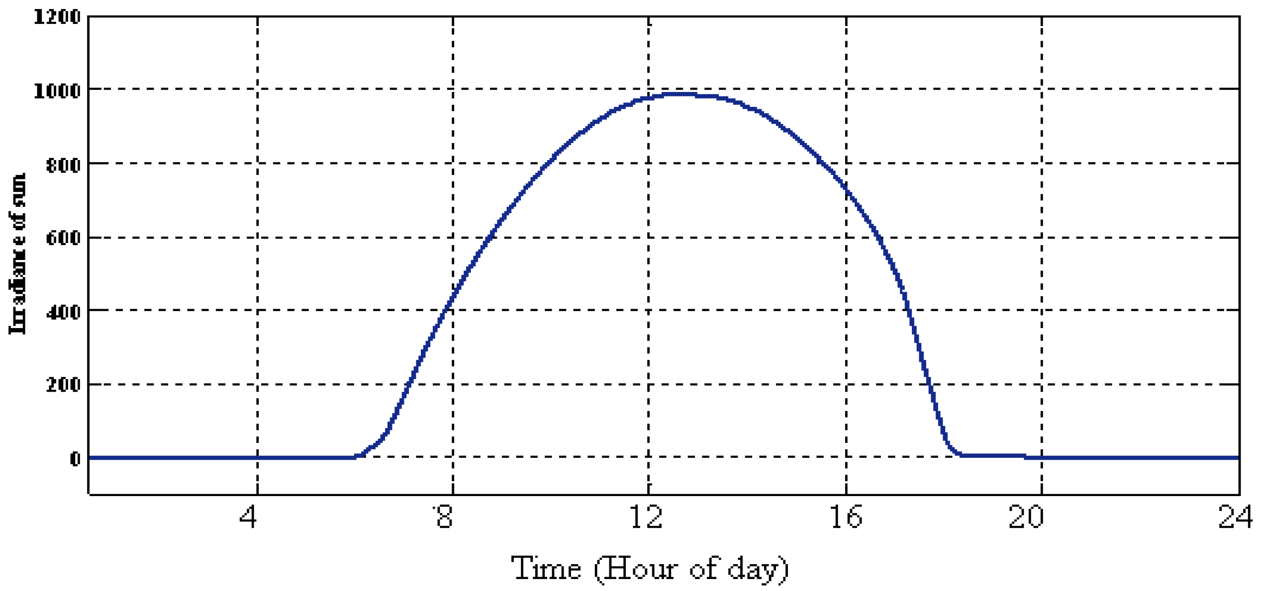
2.1. Photovoltaic
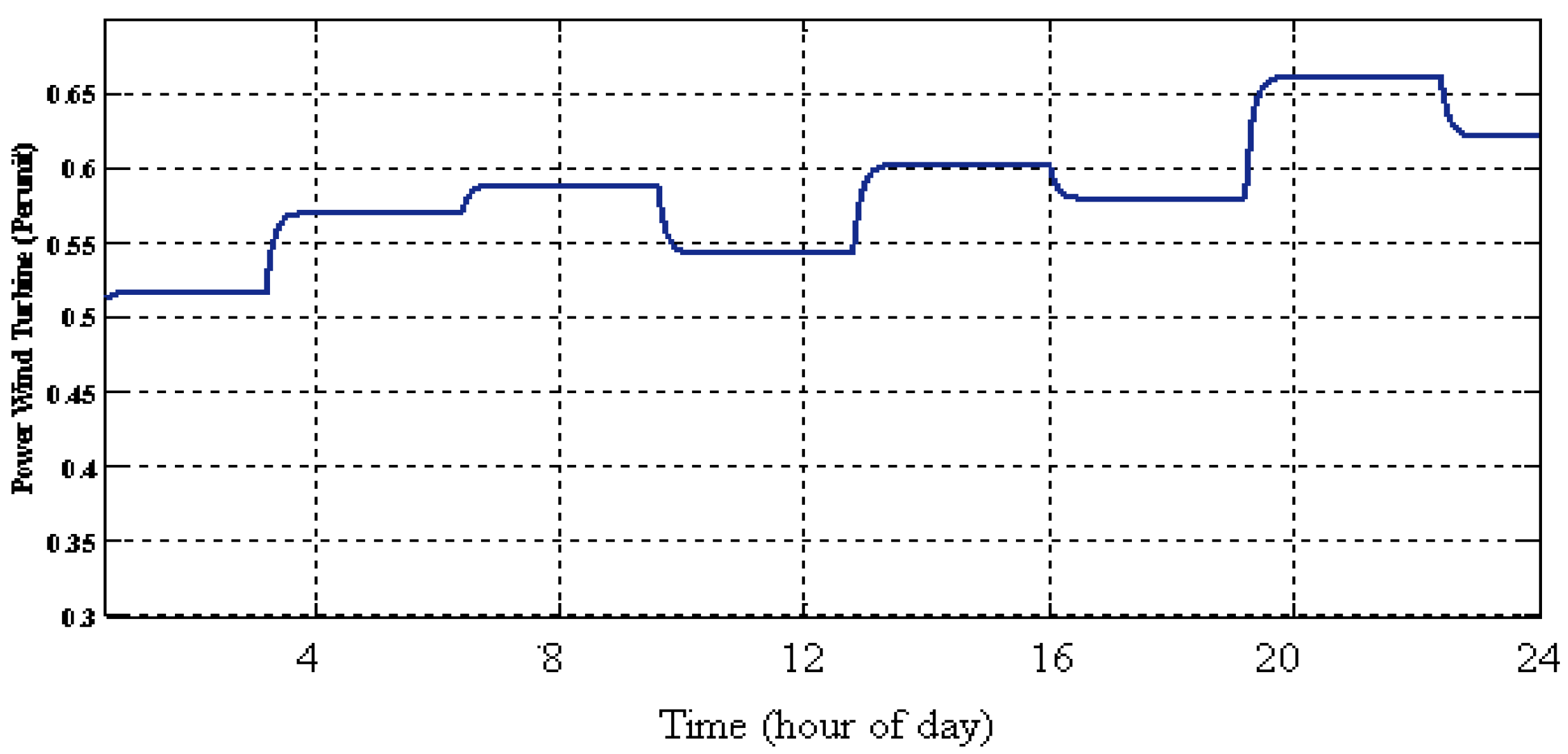
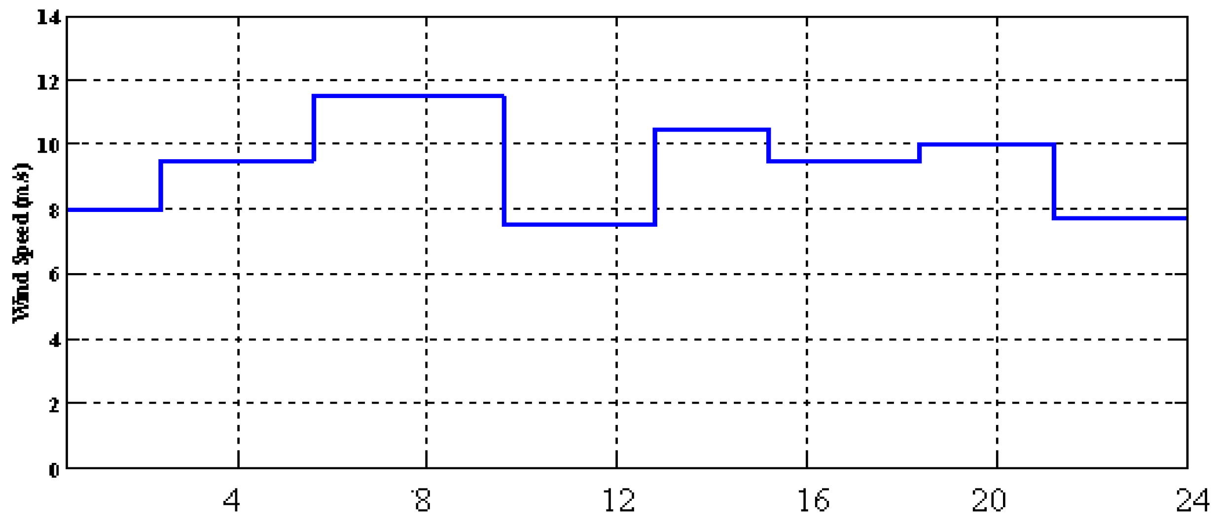
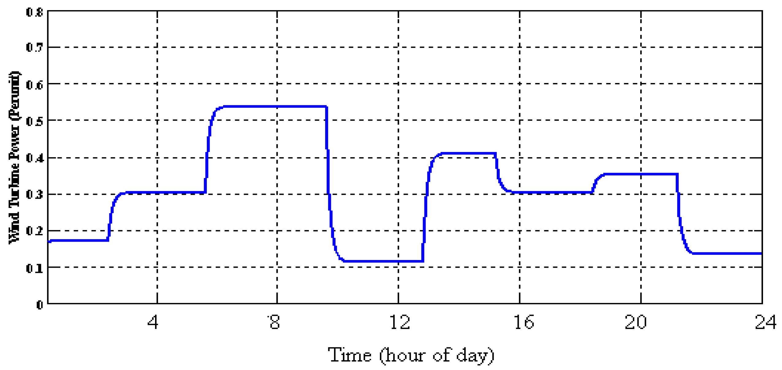
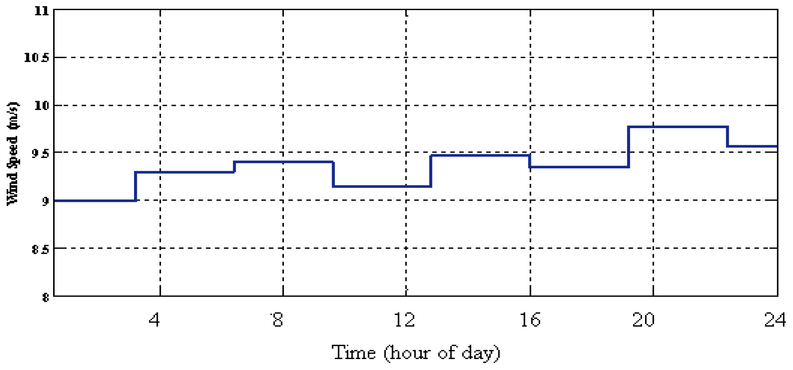
2.2. Wind Turbine
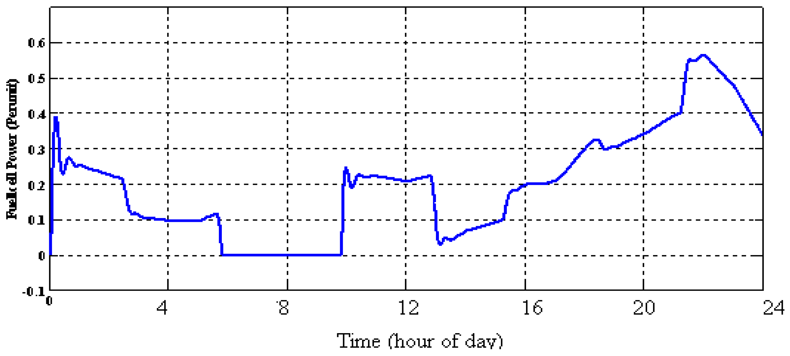
2.3. Fuel Cell
Boost DC/DC Converter
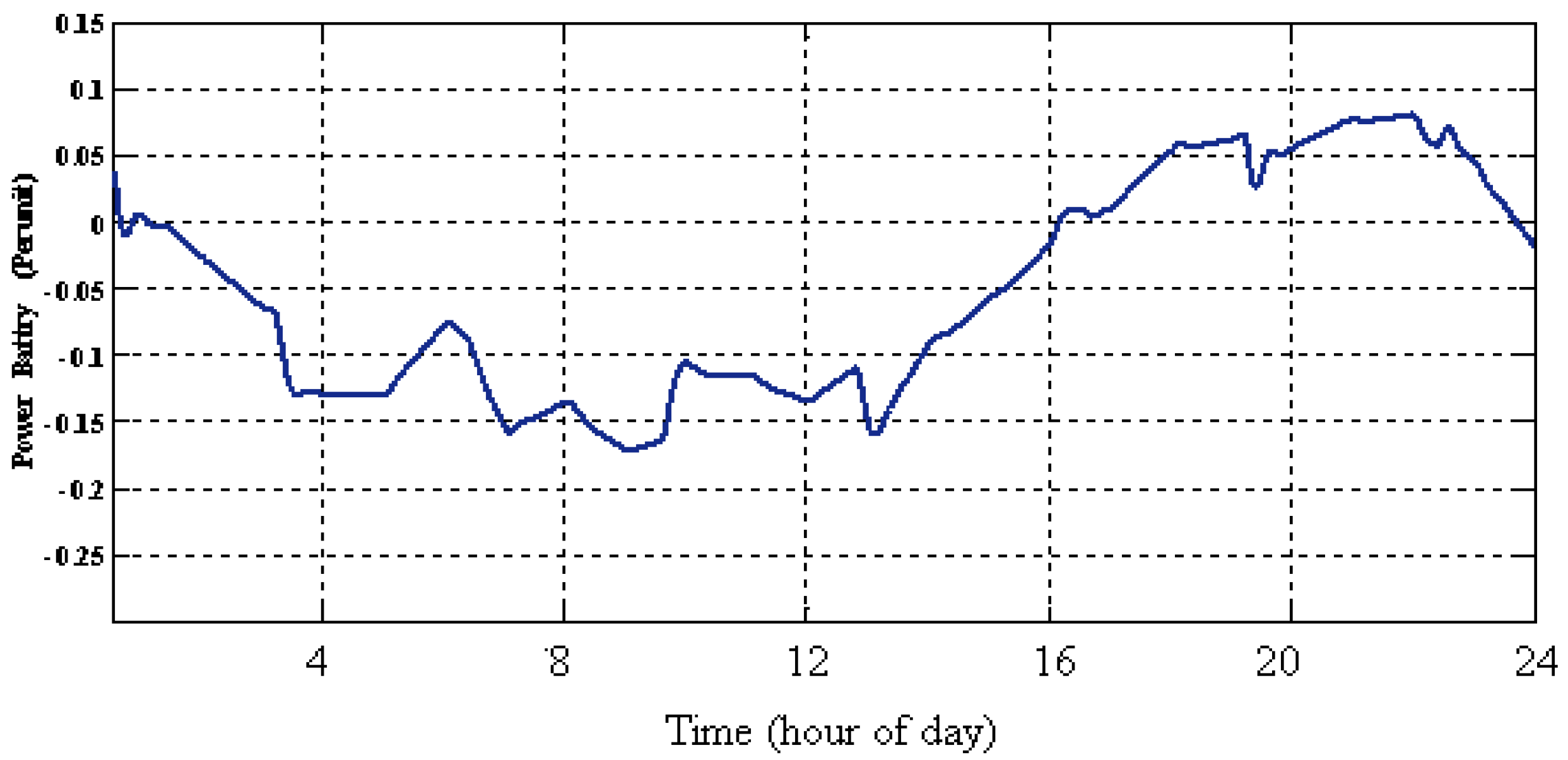
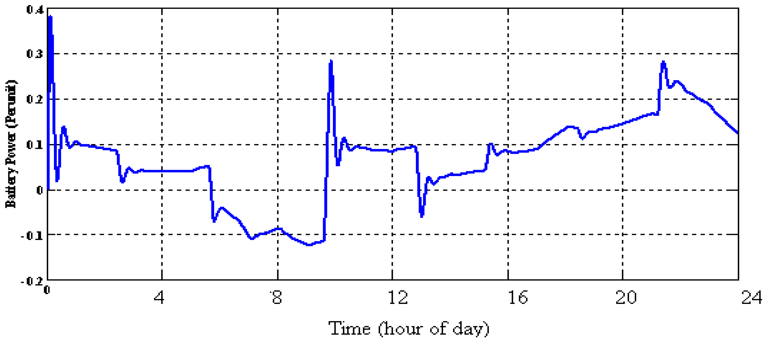
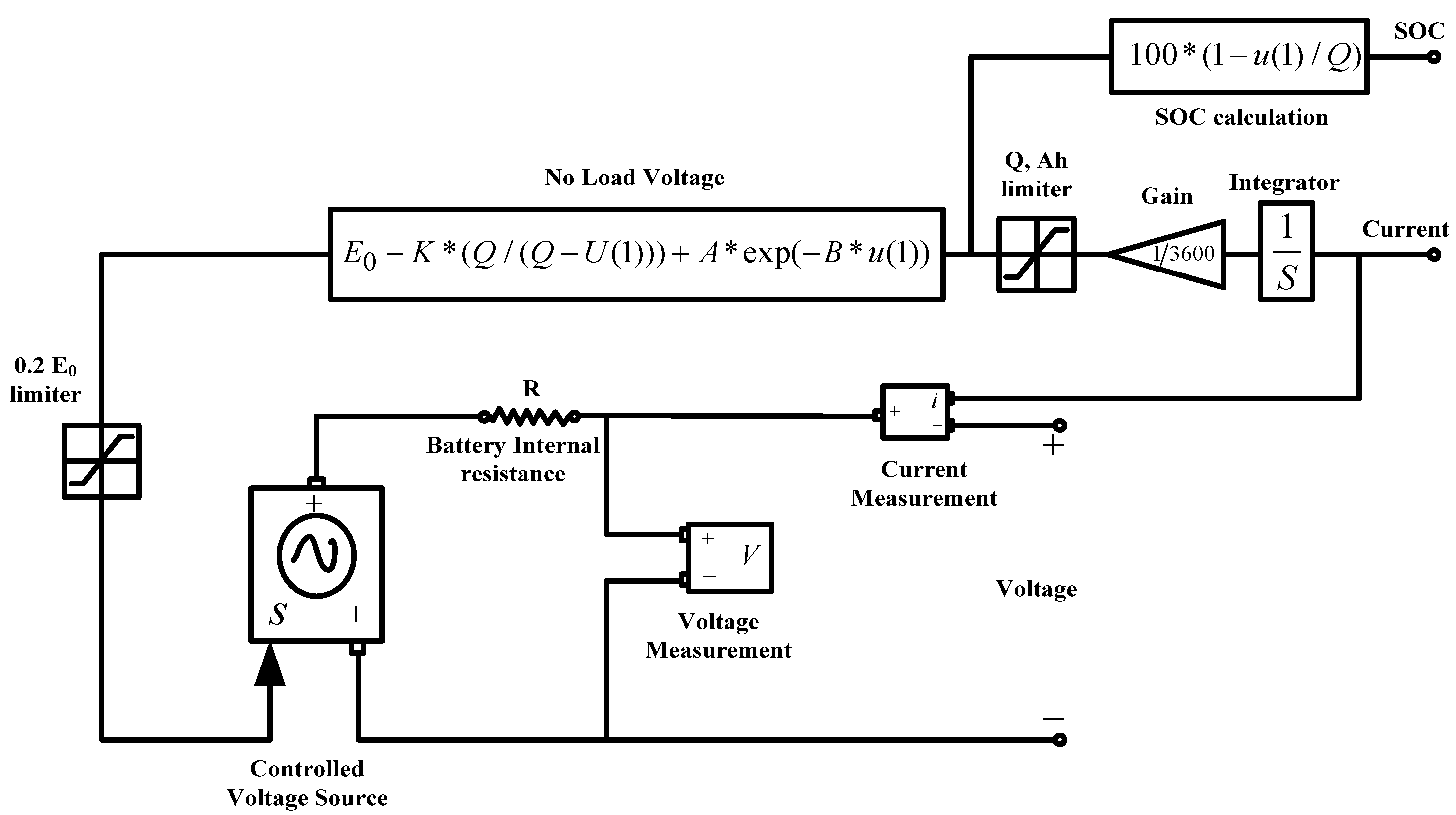
2.4. Battery Energy Storage System
3. Controller System
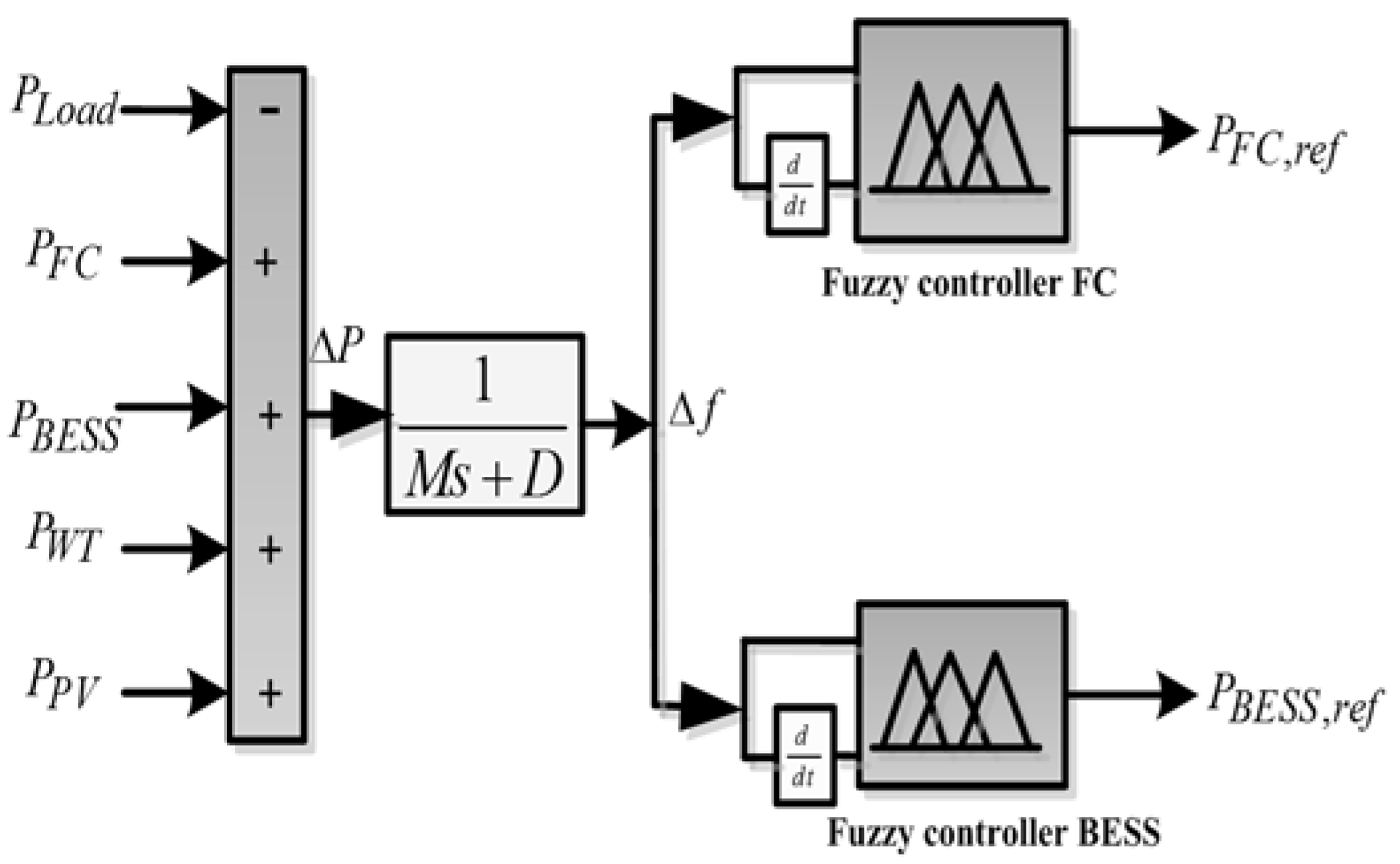
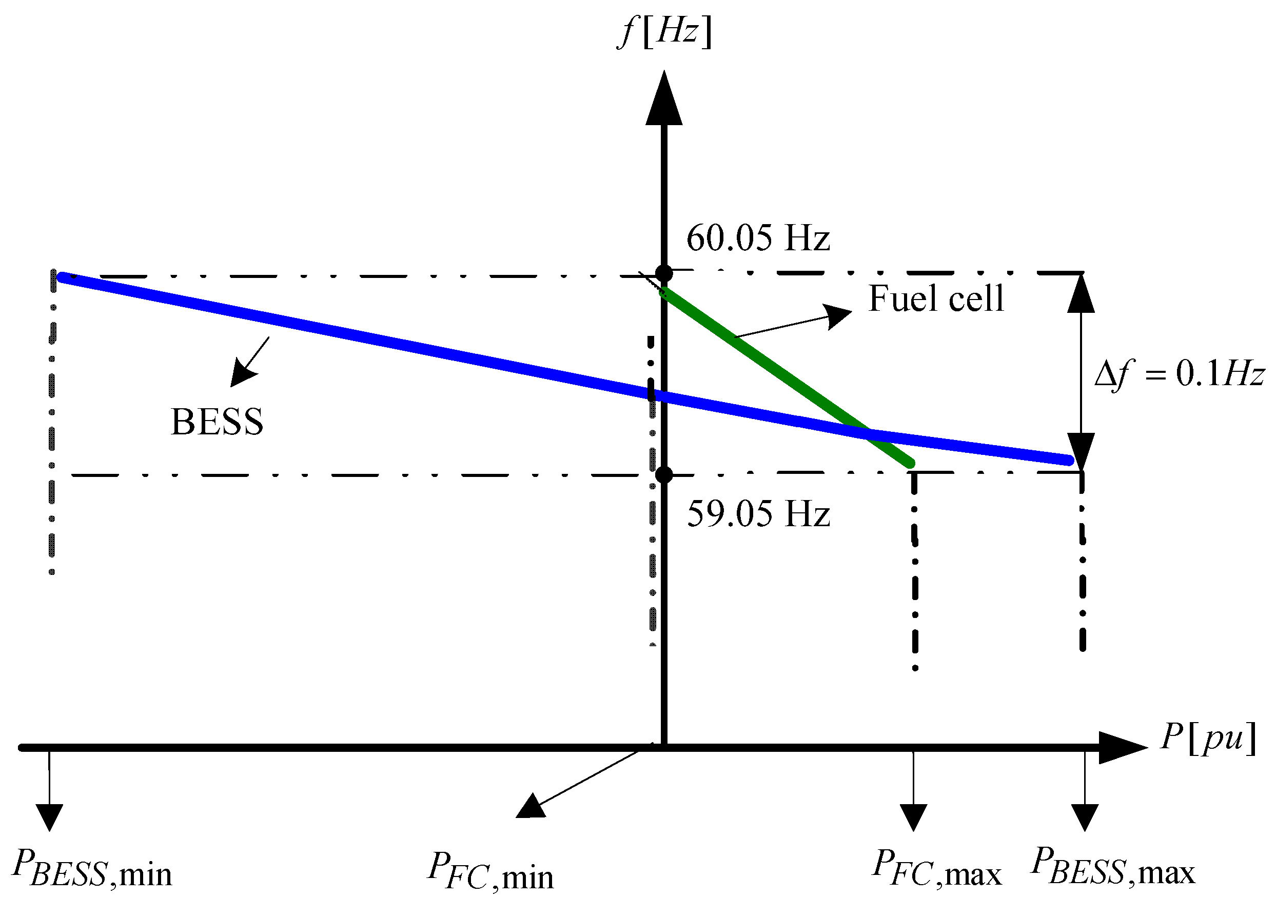
3.1. Frequency Control Concept
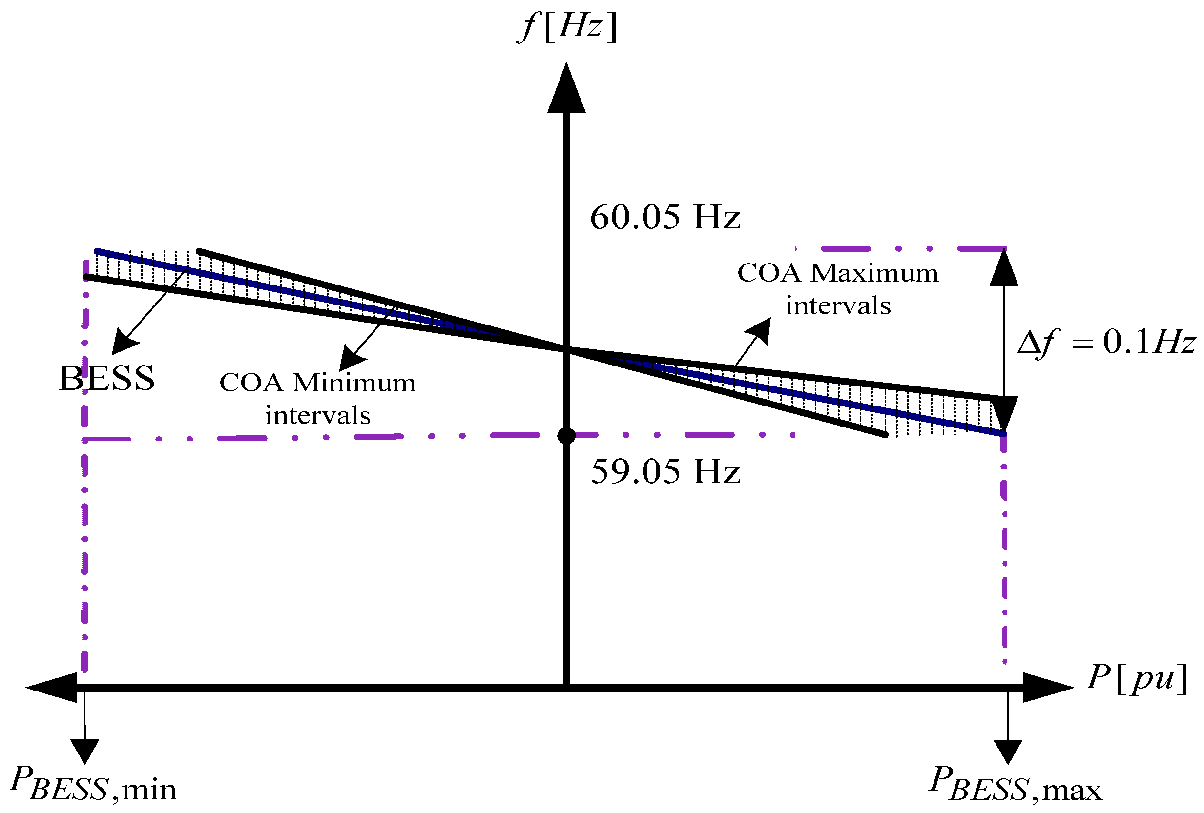
3.2. Design of the Droop Controller
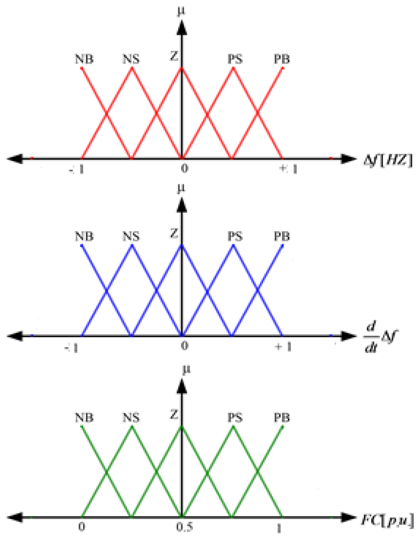
3.3. Fuzzy Logic Strategies
3.3.1. Design of a Controller for Fuel Cells System
3.3.2. Design of a Controller for Battery Energy Storage Systems
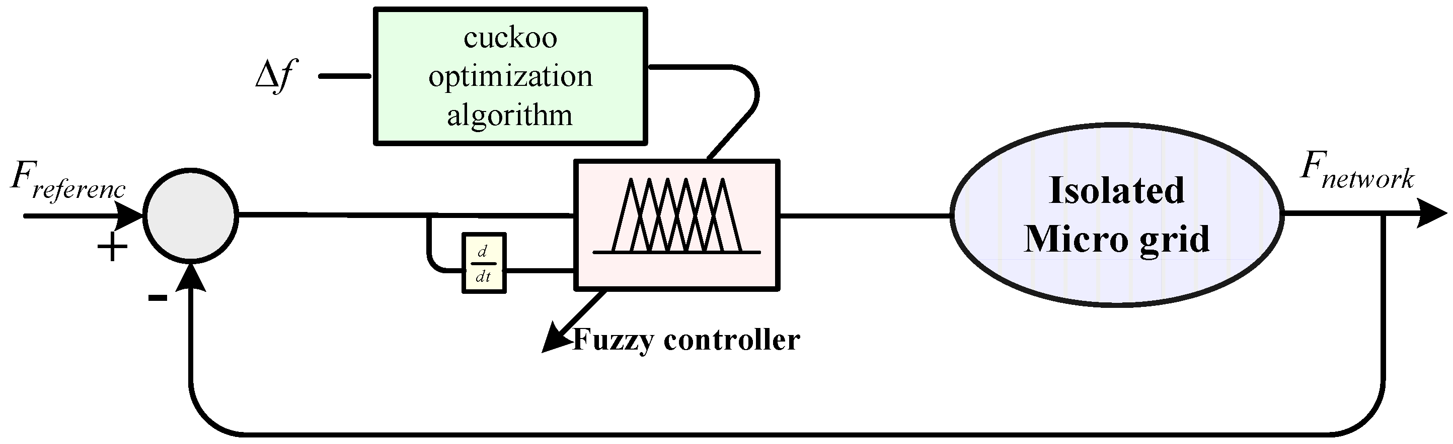
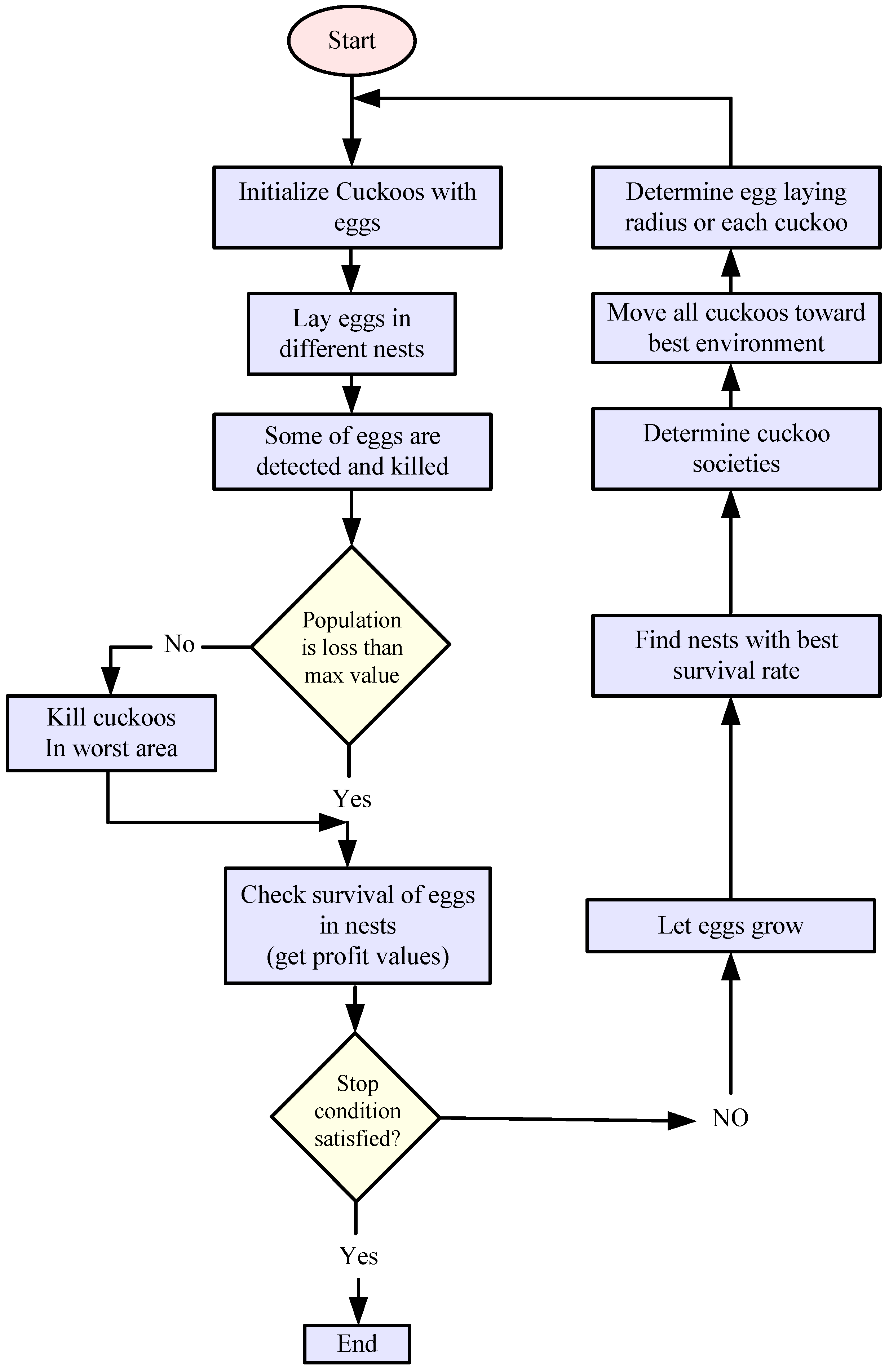
4. Cuckoo Optimization Algorithm (COA)-Fuzzy Frequency Controller
- (1)
- Optimization of membership functions
- (2)
- Optimization of coefficients of the controller
- (1)
- Input gain of the controllers that includes error and change error. (Error corresponding to frequency deviation and change error corresponding to derivative of frequency deviation).
- (2)
- The output gain that is related to the optimization of controlling signal.
Structure of Cuckoo Optimization Algorithm
5. Cuckoo Optimization Algorithm Optimized Droop Controller
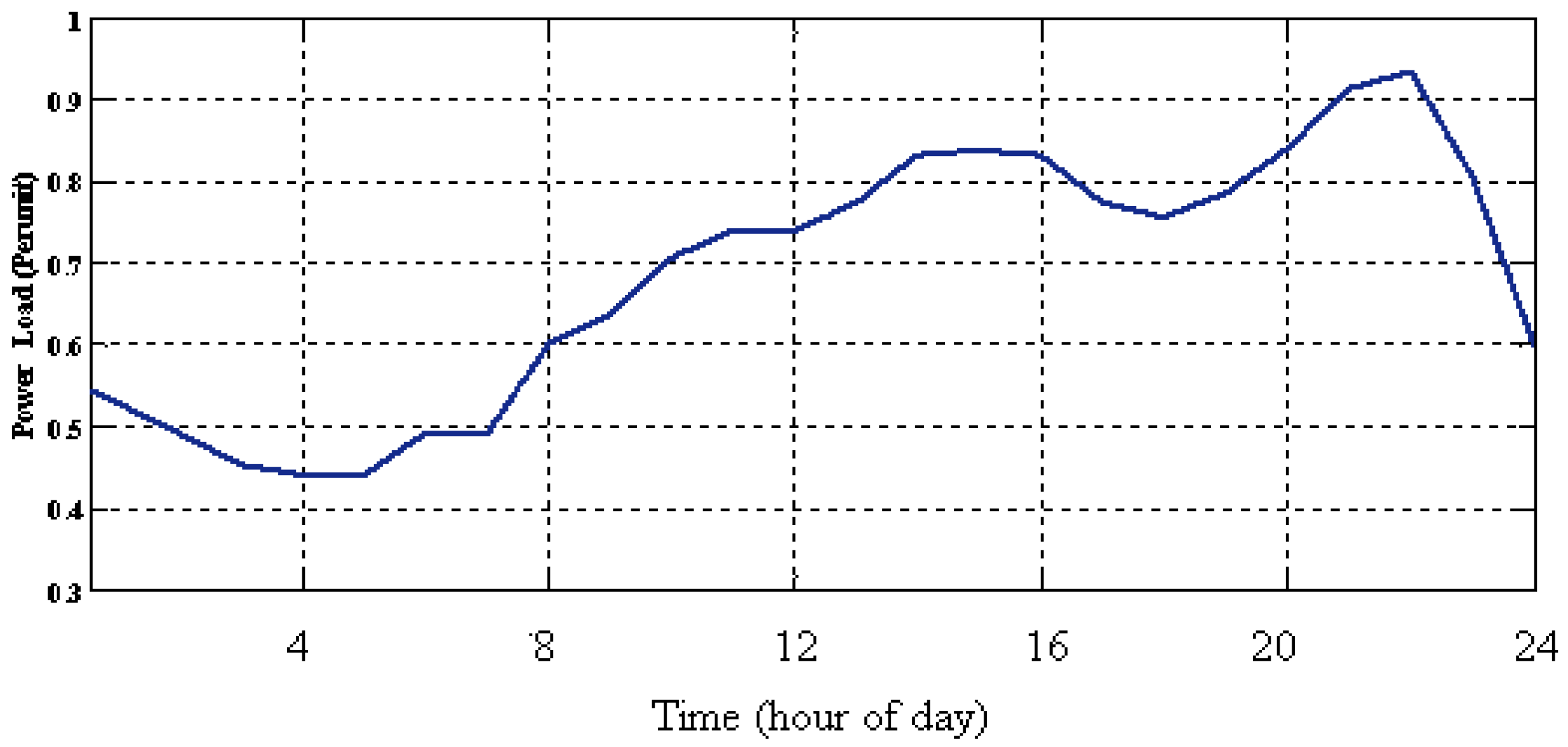
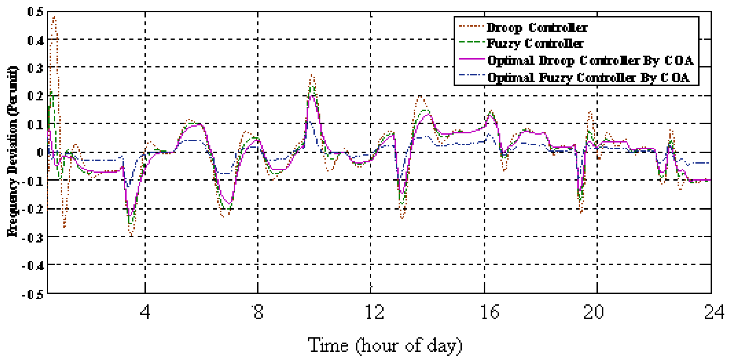
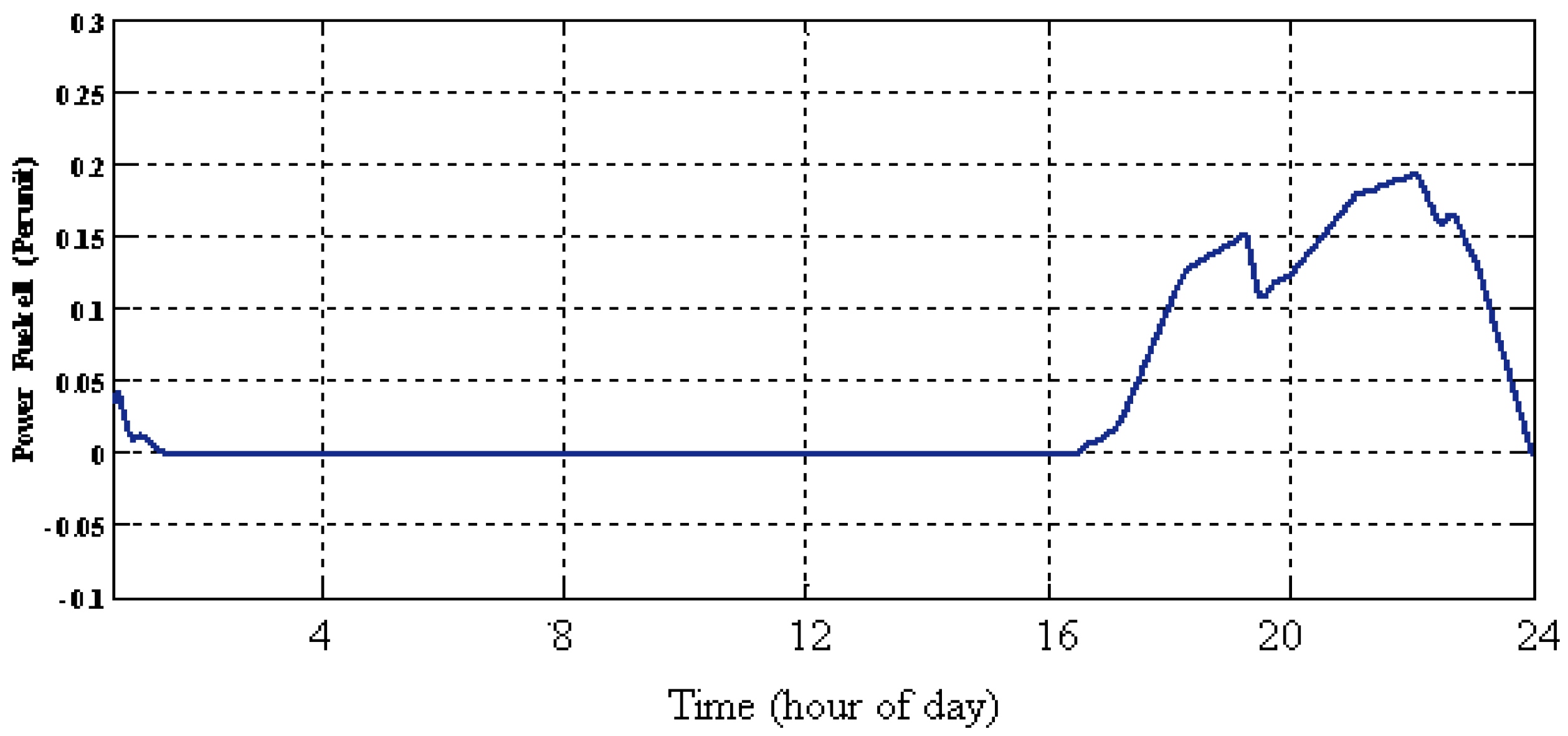
6. Simulation Results
6.1. Case Study 1
6.2. Case Study 2
7. Conclusions
Author Contributions
Conflicts of Interest
Nomenclature
| Ideal standard potential | Response time for water flow | ||
| F | Faraday’s constant | Response time for oxygen flow | |
| Fuel cell current | Short circuit current | ||
| Kan | Anode valve constant | Open circuit voltage | |
| Valve molar constant for hydrogen | Conversion efficiency | ||
| Valve molar constant for water | Fill factor | ||
| Valve molar constant for oxygen | Power at MPP | ||
| Constant (=N0/4F) | Voltage at MPP | ||
| Molecular mass of hydrogen | Current at MPP | ||
| Number of hydrogen moles in the anode channel | Series resistance | ||
| Number of cells in series in the stack | Parallel resistance | ||
| Partial pressure | Tip speed ratio | ||
| Input fuel flow | Blade angular speed (mechanical rad/s) | ||
| Output fuel flow | Blade radius (m) | ||
| Fuel flow that reacts | Wind speed (m/s) | ||
| R | Ohmic loss | Mechanical power from the wind blade (kW) | |
| RH-O | Ratio of hydrogen to oxygen | Air density (kg/m3) | |
| R | Universal gas constant | Power coefficient | |
| T | Absolute temperature | Mechanical torque from wind blade (N/m) | |
| U | Fuel Utilization factor | Volume of anode | |
| Response time for hydrogen flow | Fuel cell voltage |
References
- Kobayakawa, T.; Kandpal, T.C. Analysis of electricity consumption under a photovoltaic micro-grid system in India. Sol. Energy 2015, 116, 177–183. [Google Scholar] [CrossRef]
- Mohammadi, M.; Hosseinian, S.H.; Gharehpetian, G.B. Optimization of hybrid solar energy sources/wind turbine systems integrated to utility grids as microgrid (MG) under pool/bilateral/hybrid electricity market using PSO. Sol. Energy 2012, 86, 112–125. [Google Scholar] [CrossRef]
- Kato, K.; Murata, A.; Sakuta, K. Energy payback time and life-cycle Co2 mission of residental PV power with silicon PV module. Prog. Photovolt. Res. Appl. 1998, 6, 105–115. [Google Scholar] [CrossRef]
- Wu, Z.; Xia, X. Optimal switching renewable energy system for demand side management. Sol. Energy 2015, 114, 278–288. [Google Scholar] [CrossRef]
- Ranaboldo, M.; Domenech, B.; Reyes, G.A.; Ferrer-Martí, L.; Moreno, R.P.; García-Villoria, A. Off-grid community electrification projects based on wind and solar energies: A case study in Nicaragua. Sol. Energy 2015, 117, 268–281. [Google Scholar] [CrossRef] [Green Version]
- Kayal, P.; Chanda, C.K. A multi-objective approach to integrate solar and wind energy sources with electrical distribution network. Sol. Energy 2015, 112, 397–410. [Google Scholar] [CrossRef]
- Veneri, O. Technologies and Applications for Smart Charging of Electric and Plug-In Hybrid Vehicles; Springer: Naples, Italy, 2017. [Google Scholar]
- Glavin, M.E.; Hurley, W.G. Optimisation of a photovoltaic battery ultracapacitor hybrid energy storage system. Sol. Energy 2012, 86, 3009–3020. [Google Scholar] [CrossRef]
- Trifkovic, M.; Sheikhzadeh, M.; Nigim, K.; Daoutidis, P. Modeling and Control of a Renewable Hybrid Energy System with Hydrogen Storage. IEEE Trans. Control Syst. Technol. 2014, 22, 169–179. [Google Scholar] [CrossRef]
- Onar, O.C.; Uzunoglu, M.; Alam, M.S. Modeling, control and simulation of an autonomous wind turbine/photovoltaic/fuel cell/ultra-capacitor hybrid power system. J. Power Sources 2008, 185, 1273–1283. [Google Scholar] [CrossRef]
- Onar, O.C.; Uzunoglu, M.; Alam, M.S. Dynamic modeling, design and simulation of a wind/fuel cell/ultra-capacitor-based hybrid power generation system. J. Power Sources 2006, 161, 707–722. [Google Scholar] [CrossRef]
- Ipsakis, D.; Voutetakis, S.; Seferlis, P.; Stergiopoulos, F.; Elmasides, C. Power management strategies for a stand-alone power system using renewable energy sources and hydrogen storage. Int. J. Hydrog. Energy 2009, 34, 7081–7095. [Google Scholar] [CrossRef]
- Arboleya, P.; Diaz, D.; Guerrero, J.M.; Garcia, P.; Briz, F.; Gonzalez-Moran, C.; Gomez Aleixandre, J. An improved control scheme based in droop characteristic for microgrid converters. Electric Power Syst. Res. 2010, 80, 1215–1221. [Google Scholar] [CrossRef]
- Goya, T.; Omine, E.; Kinjyo, Y.; Senjyu, T.; Yona, A.; Urasaki, N.; Funabashi, T. Frequency control in isolated island by using parallel operated battery systems applying H∞ control theory based on droop characteristics. IET Renew. Power Gener. 2011, 5, 160–166. [Google Scholar] [CrossRef]
- Bevrani, H.; Daneshmand, P.R. Fuzzy Logic-Based Load-Frequency Control Concerning High Penetration of Wind Turbines. IEEE Syst. J. 2012, 6, 173–180. [Google Scholar] [CrossRef]
- Nayeripour, M.; Hoseintabar, M.; Niknam, T. Frequency deviation control by coordination control of FC and double-layer capacitor in an autonomous hybrid renewable energy power generation system. Renew. Energy 2011, 36, 1741–1746. [Google Scholar] [CrossRef]
- Wang, L.; Lee, D.J.; Lee, W.J.; Chen, Z. Analysis of a novel autonomous marine hybrid power generation/energy storage system with a high-voltage direct current link. J. Power Sources 2008, 185, 1284–1292. [Google Scholar] [CrossRef]
- Koutroulis, E.; Kalaitzakis, K.; Voulgaris, N.C. Development of a microcontroller-based, photovoltaic maximum power point tracking control system. IEEE Trans. Power Electron. 2001, 16, 46–54. [Google Scholar] [CrossRef]
- Esram, T.; Chapman, P.L. Comparison of Photovoltaic Array Maximum Power Point Tracking Techniques. IEEE Trans. Energy Convers. 2007, 22, 439–449. [Google Scholar] [CrossRef]
- Zhang, F.; Maddy, J.; Premier, G.; Guwy, A. Novel current sensing photovoltaic maximum power point tracking based on sliding mode control strategy. Sol. Energy 2015, 118, 80–86. [Google Scholar] [CrossRef]
- Chen, P.-C.; Chen, P.-Y.; Liu, Y.-H.; Chen, J.-H.; Luo, Y.-F. A comparative study on maximum power point tracking techniques for photovoltaic generation systems operating under fast changing environments. Sol. Energy 2015, 119, 261–276. [Google Scholar] [CrossRef]
- Wang, C. Modeling and Control of Hybrid Wind/Photovoltaic/Fuel Cell Distributed Generation Systems. Ph.D. Thesis, Montana State University, Bozeman, MT, USA, 2006. [Google Scholar]
- Abdeddaim, S.; Betka, A.; Drid, S.; Becherif, M. Implementation of MRAC controller of a DFIG based variable speed grid connected wind turbine. Energy Convers. Manag. 2014, 79, 281–288. [Google Scholar] [CrossRef]
- Sendjaja, A.Y.; Kariwala, V. Decentralized Control of Solid Oxide Fuel Cells. IEEE Trans. Ind. Inform. 2011, 7, 163–170. [Google Scholar] [CrossRef]
- Hajizadeh, A.; Golkar, M.A. Intelligent power management strategy of hybrid distributed generation system. Int. J. Electr. Power Energy Syst. 2007, 29, 783–795. [Google Scholar] [CrossRef]
- Senjyu, T.; Nakaji, T.; Uezato, K.; Funabashi, T. A hybrid power system using alternative energy facilities in isolated island. IEEE Trans. Energy Convers. 2005, 20, 406–414. [Google Scholar] [CrossRef]
- Rajesh, R.; Mabel, M.C. Efficiency analysis of a multi-fuzzy logic controller for the determination of operating points in a PV system. Sol. Energy 2014, 99, 77–87. [Google Scholar] [CrossRef]
- Safari, S.; Ardehali, M.M.; Sirizi, M.J. Particle swarm optimization based fuzzy logic controller for autonomous green power energy system with hydrogen storage. Energy Convers. Manag. 2013, 65, 41–49. [Google Scholar] [CrossRef]
- Laghari, J.A.; Mokhlis, H.; Bakar, A.H.A.; Mohamad, H. Application of computational intelligence techniques for load shedding in power systems: A review. Energy Convers. Manag. 2013, 75, 130–140. [Google Scholar] [CrossRef]
- Berrazouane, S.; Mohammedi, K. Parameter optimization via cuckoo optimization algorithm of fuzzy controller for energy management of a hybrid power system. Energy Convers. Manag. 2014, 78, 652–660. [Google Scholar] [CrossRef]
- Gandomi, A.; Yang, X.-S.; Alavi, A. Cuckoo search algorithm: A metaheuristic approach to solve structural optimization problems. Eng. Comput. 2013, 29, 17–35. [Google Scholar] [CrossRef]


| Parameters | Value | Unit |
|---|---|---|
| 2.664 | A | |
| 5.472 | V | |
| 1.324 | Ω | |
| 87.72 | V | |
| 70.731 | V | |
| 2.448 | A | |
| 1000 | W/m2 | |
| 25 | °C | |
| 5 × 10⁴ | J/(°C·m2) | |
| A | 1.5 | m2 |
| 0.9 | ||
| 30 | W/(°C·m2) |
| Error | NB | NS | Z | PS | PB | |
|---|---|---|---|---|---|---|
| Error Changes | ||||||
| NB | PB | PS | Z | Z | NS | |
| NS | PB | PS | Z | NS | NS | |
| Z | PS | Z | NS | NS | NB | |
| PS | Z | NS | NB | NB | NB | |
| PB | NS | NB | NB | NB | NB | |
| Error | NB | NS | N | PS | PB | |
|---|---|---|---|---|---|---|
| Error Changes | ||||||
| NB | PB | PS | N | N | NS | |
| NS | PB | PS | N | NS | NS | |
| N | PS | N | NS | NS | NS | |
| PS | PS | N | NS | NS | NB | |
| PB | N | NB | NB | NB | NB | |
| Optimization Algorithm | GA | PSO | COA |
|---|---|---|---|
| Error of Frequency Deviation | 0.1243 | 0.112 | 0.089 |
© 2017 by the authors. Licensee MDPI, Basel, Switzerland. This article is an open access article distributed under the terms and conditions of the Creative Commons Attribution (CC BY) license (http://creativecommons.org/licenses/by/4.0/).
Share and Cite
Einan, M.; Torkaman, H.; Pourgholi, M. Optimized Fuzzy-Cuckoo Controller for Active Power Control of Battery Energy Storage System, Photovoltaic, Fuel Cell and Wind Turbine in an Isolated Micro-Grid. Batteries 2017, 3, 23. https://doi.org/10.3390/batteries3030023
Einan M, Torkaman H, Pourgholi M. Optimized Fuzzy-Cuckoo Controller for Active Power Control of Battery Energy Storage System, Photovoltaic, Fuel Cell and Wind Turbine in an Isolated Micro-Grid. Batteries. 2017; 3(3):23. https://doi.org/10.3390/batteries3030023
Chicago/Turabian StyleEinan, Mohsen, Hossein Torkaman, and Mahdi Pourgholi. 2017. "Optimized Fuzzy-Cuckoo Controller for Active Power Control of Battery Energy Storage System, Photovoltaic, Fuel Cell and Wind Turbine in an Isolated Micro-Grid" Batteries 3, no. 3: 23. https://doi.org/10.3390/batteries3030023