1. Introduction
Lithium-ion batteries (LIBs) are statistically safe, with a 1 in 10 million failure rate established during the manufacturing (rather than due to field ageing) and such failures are considered an exception and not a reliability problem [
1]. However, with billions of cells in use globally, failures are to be expected and are a cause of health and safety concern. To eliminate these effectively, we need techniques to fully understand their root causes [
2].
In 2006, a 1-in-200,000 failure rate triggered a recall of almost six million LIB packs used in several brands of notebook computers [
3]. Sony, the maker of the lithium-ion cells in question, pointed out that on rare occasions microscopic metal particles may come into contact with other parts of the battery cell, leading to a short circuit within the cell [
1]. In 2013, Boeing had its newest and most advanced aircraft, the 787 Dreamliner, globally grounded due to incidences of fire that emanated from a battery powering an APU (auxiliary power unit) on board flight JA829 [
4,
5,
6]. At least three other reported incidences have affected other airliners with a significant fleet of 787 aircrafts [
7]. There is a continued drive for faster innovations in Li-ion cell formats, regardless of type and dimension, to meet advanced performance criteria. We propose that effective component characterisation is critical over multiple scales if we are to meaningfully interpret and reduce failure rates.
Within Li-ion cells an internal short circuit can generate sufficient heat to initiate exothermic side reactions involving energy dense and sometimes volatile components within the cell—when these proceed out of control they cause a thermal runaway resulting in fires [
8]. Additional electrical, mechanical, or thermal abuse conditions may also contribute to such a reaction cascade in certain circumstances and be associated with thermal runaway to adversely affect Li-ion cells [
9].
1.1. The Thermal Runaway Cascade
The primary functional components of a lithium-ion cell are the anode and cathode (each taking the form of a metallic foil coated with electrochemically active components) and electrolyte (typically a liquid organic compound). During the charge process Li ions move from the cathode through the separator to the anode, whilst electrons flow through an external circuit. Causes of short circuiting may be external or internal. The latter may include foreign contaminants or Li-dendrites penetrating through the separator (an insulating porous film separating anode and cathode). Anything that results in electrical contact between anode and cathode [
10] will result in a short circuit.
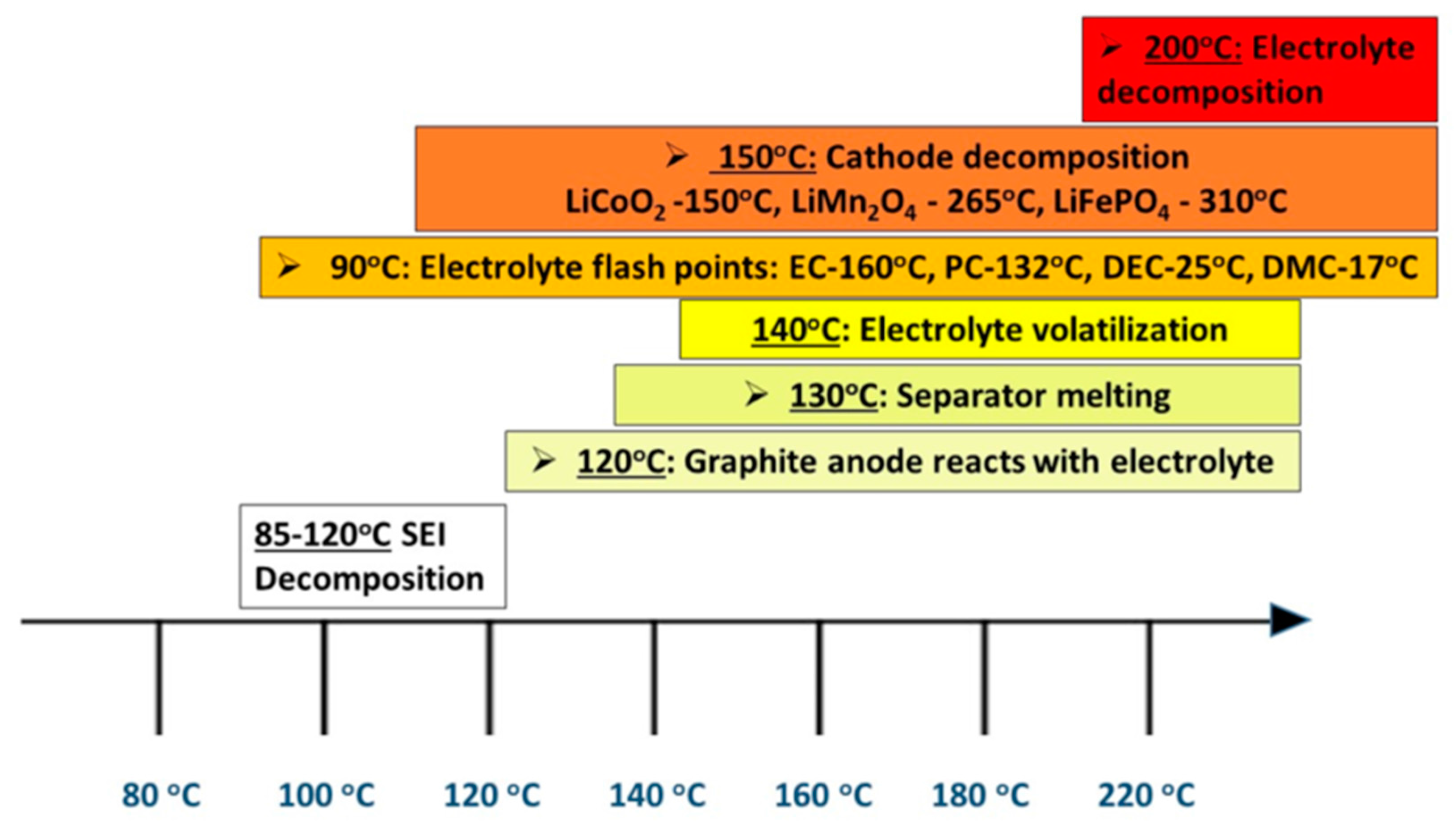
Prior to commercial availability, a battery will undergo a formation cycle. This allows for the creation of a protective layer on the electrodes, generated from the decomposition of a small amount of electrolyte solution on the surface of the electrodes. This is termed the ‘solid electrolyte interphase’ (SEI). Following a short circuit event the localised temperature inside the cell begins to rise and at 100 °C the SEI film begins to decompose [
11]. A series of exothermic reactions follow between SEI compounds and electrolyte solvents such as ethylene carbonate (EC) and diethyl carbonate (DEC). When this cascade of reactions proceeds uninterrupted, it causes a rapid elevation of the internal temperature whereby a series of reactions can generate large volumes of flammable hydrocarbon gases, which will vent to atmosphere—see
Figure 1 [
12,
13,
14,
15].
Cathode oxide materials can reduce in exothermic disproportionation reactions e.g., lithium cobalt oxide breakdown outlined in Equation (1) [
13,
16]. Charged Li
xCoO
2 (lithiated) can decompose, releasing oxygen at elevated temperatures [
17]. Equation (1) shows the complete reduction to cobalt metal that will only occur if sufficient reducing agent (solvent) is present [
16].
Therefore, in the context of the continued widespread use of this cathode material, it will potentially be problematic only when conditions warrant thermal stability, as compared with e.g., lithium iron phosphate [
18]. The choice of electrode chemistries is often a question of energy density vs. rate requirements and such things can often result in trade-offs that dictate ultimate performance.
Investigating and understanding the root causes of cell failures allow us to re-engineer the way cells are constructed or manufactured to then mitigate the safety hazards [
19] associated with the likelihood of internal short circuits in LIBs. It is not straightforward to capture all failure origins in batteries as they are closed systems. Operando characterisation techniques have become a popular area in battery research and are proving to be very valuable. They allow us to measure or visualise occurrences in real-time, without stopping operation and opening the battery. This is a very high priority and active area within the energy storage research community [
20].
1.2. How was Battery Manufacturing the Cause of the Faults?
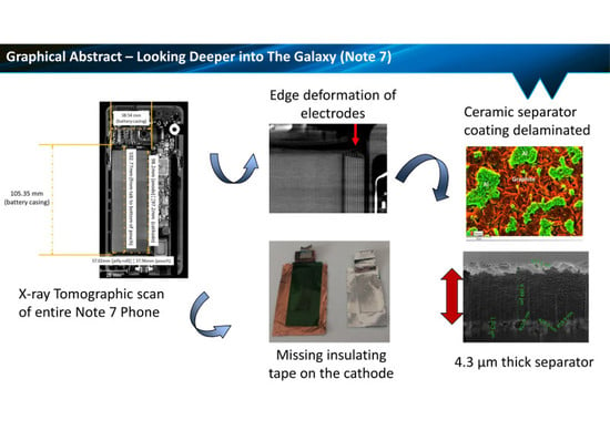
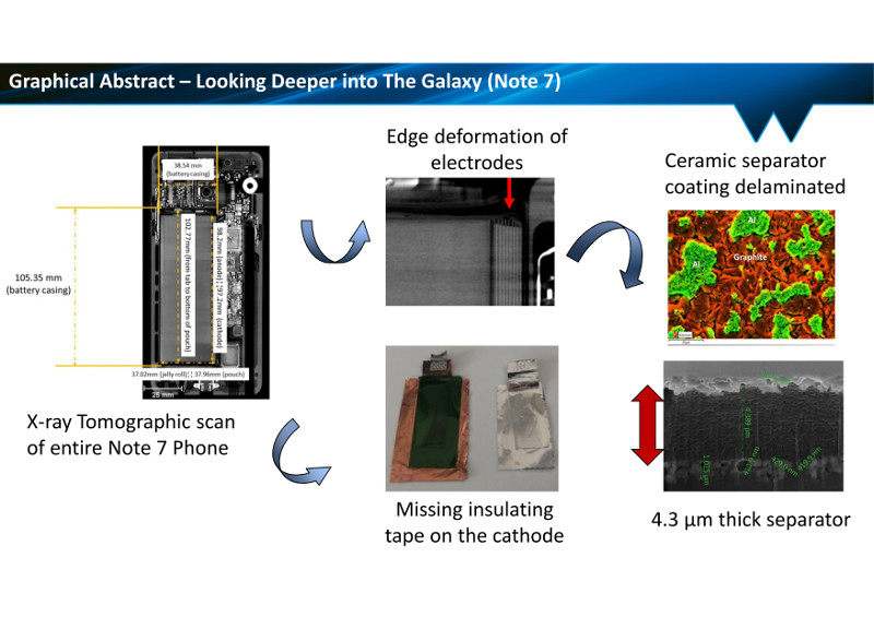
In 2016 there was a total product recall of the Samsung Galaxy Note 7 which has cost the company an estimated
$17 billion [
21], with the reported cause of the fire incidences claimed to be attributable to a “non-optimized manufacturing process relating to the battery”. The official investigation by Samsung highlighted several key areas to which the phone fires were attributed. The errors reported were both in the design and manufacturing of the batteries and were reported to include:
- (i)
Insufficient insulation material within the batteries;
- (ii)
Not enough room to safely accommodate the battery;
- (iii)
Welding burrs on the positive electrode resulting in penetration of the insulating tape (on the tabs) and separator.
Additional independent investigations by three organisations; UL, Exponent, and TÜV—Rheinland analysed hundreds of cells and added more insight into root cause analysis and abuse approaches [
22]. Their respective press releases expanded on the suspected failure modes reported from the two battery companies—Manufacturers A and B—used to supply the cells for the Note 7 manufacture.
1.3. Reported Failure Suspicions and Battery Component Causes
Two additional press releases presented investigations of batteries from two different manufacturers [
22,
23]. Cells from Manufacturer A and B were described in the root cause analyses reports, citing that the thermal failure events were due to unintended anode deformation in the corner of the cell closest to the negative tab. Cells from Manufacturer B were reported to have no such deficiencies but were reported to contain welding defects tall enough to bridge the distance to the anode tab. Additionally, insulating tape was found to be missing over the cathode electrode tab.
The second investigation tested 10 devices containing cells from Manufacturer A alongside 10 from Manufacturer B and summarised the suspected causes of the thermal failures as a combination of:
- (i)
Internal short circuit (ISC) at the upper right corner of the cells;
- (ii)
Repeated deformation of the separator at corner locations;
- (iii)
Missing insulating tape on the cathode tab;
- (iv)
Poor alignment of components;
- (v)
Uneven charge status and;
- (vi)
Thinner separator compared with others used in previous devices.
This study seeks to corroborate the reported findings by elucidating—across multiple scales—all the microstructural aspects inside the battery but to add to the component and material-level details and resolution. We capture deeper analysis of key components compared with the press releases issued. Several dimensional levels will be considered.
2. Results and Discussion
2.1. Electrochemical Characterisation
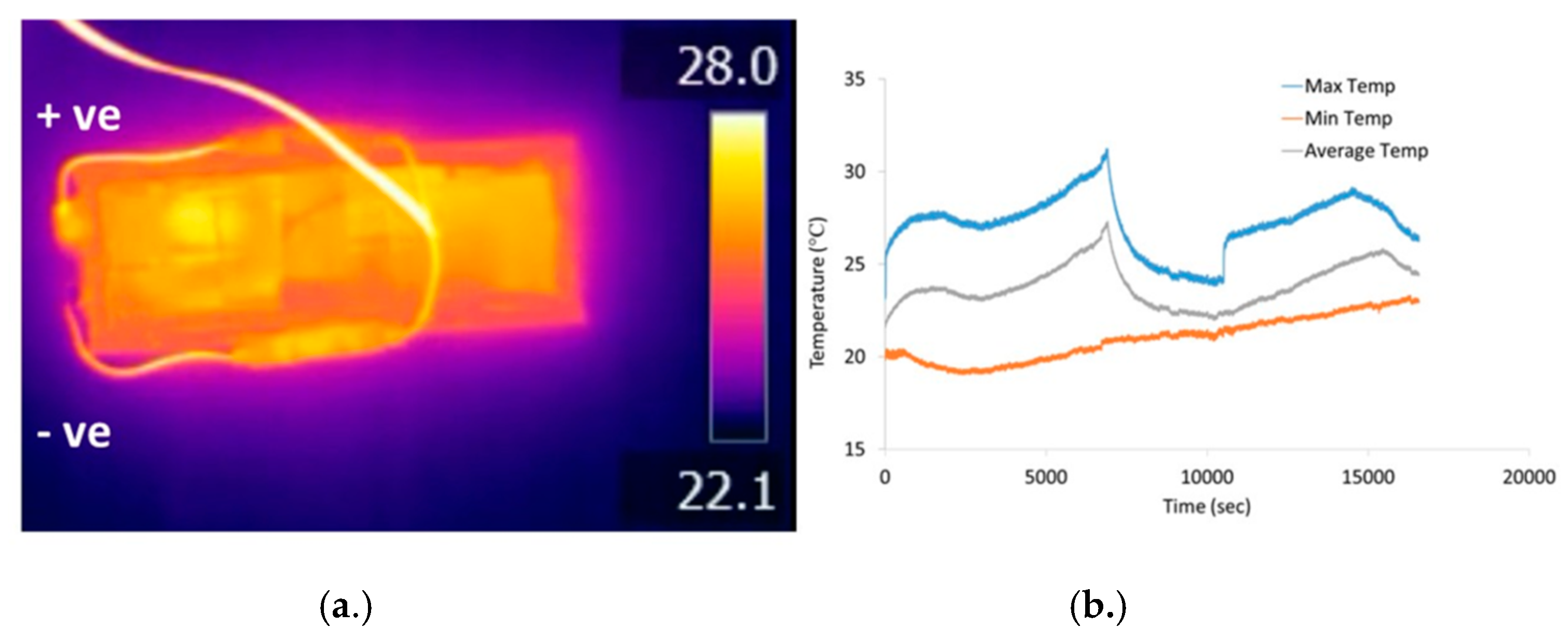
Figure 2a shows the temperature profile (maxima and minima) as a function of charging time with periodic thermal imaging. For the duration of the charging step, the temperature of the cell did not rise above 32 °C at a charging rate of C/2.
A noticeable temperature difference of up to 3 °C can be seen across the cell from top to bottom. The higher temperature side is where the positive terminal is sited and this is where current transport occurs with the cathodes. The current collectors for this electrode are made of aluminium, whereas the anode current collectors are made of copper. Cu and Al have differing thermal conductivities of 401 and 205 W/(m K) and electrical resistivities of 1.72 × 10⁻⁸ and 2.65 × 10⁻⁸ Ω−m respectively, hence the anode has lower electrical resistance and the capacity to dissipate heat more quickly. Additionally, the Al current collector is 5 µm thicker than the Cu current collector at the anode and can thus contribute to slowing down heat transfer.
2.2. X-ray CT Characterisation of Device and Internal Battery Features
X-ray micro-tomography scans were performed at three levels: (a) the intact mobile phone; (b) the battery; and (c) the battery components, which are the electrodes and separator.
Figure 3a shows X-ray tomographic scans of regions of the cell within the device.
2.2.1. Battery Cell Characterisation
Consistent with device findings ascribed to cells that were produced at Manufacturer A, from the enlarged images in
Figure 3a the feature that resemble a fallen row of dominoes the bottom section edge of the prismatic from unintended damage to the negative electrode windings. The corners are folded over and thought to be caused by a pouch design with insufficient internal space around certain regions of cell content. There is a clear deformation at the cell here, thought to derive from the manufacturing and assembly process.
The potential implications of this, taking into account typical expected dimensional manufacturing tolerances, are to increase the likelihood of an internal cell short circuit and subsequent thermal failure during normal operation.
2.2.2. Cell Component Characterisation
Upon forensic disassembly of the cell and subsequent unravelling of the electrodes there were visible areas of coating irregularities on both the electrodes and the separator—see
Figure 3b. On the anode there is coating delamination on several edge regions, with cracking of the coating at the folded areas. This reflects greater pressure exerted on these regions and could indicate the potential for separator damage in these zones, leading to an internal short circuit. Additionally, any material detached from the electrode, if it were to enter the electrode stack, could increase local mechanical pressure on the separator.
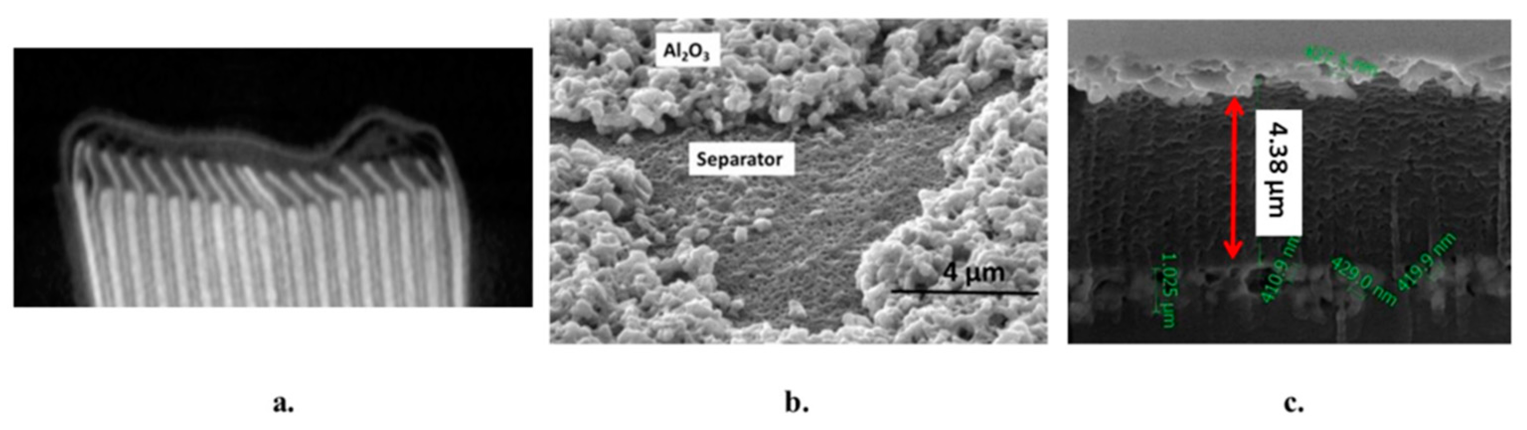
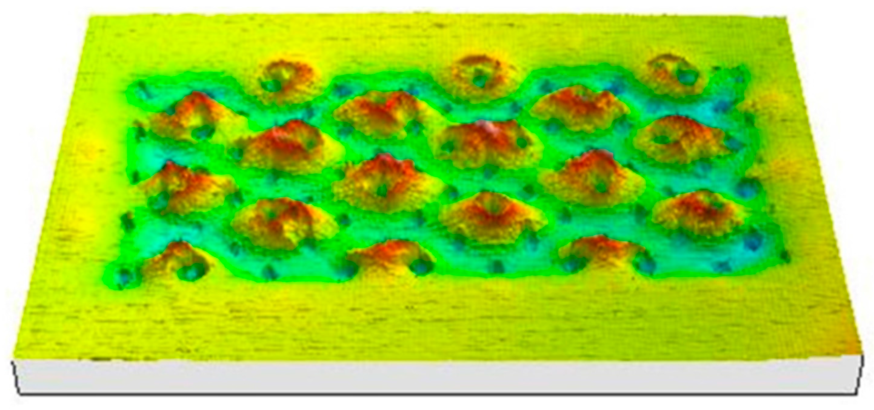
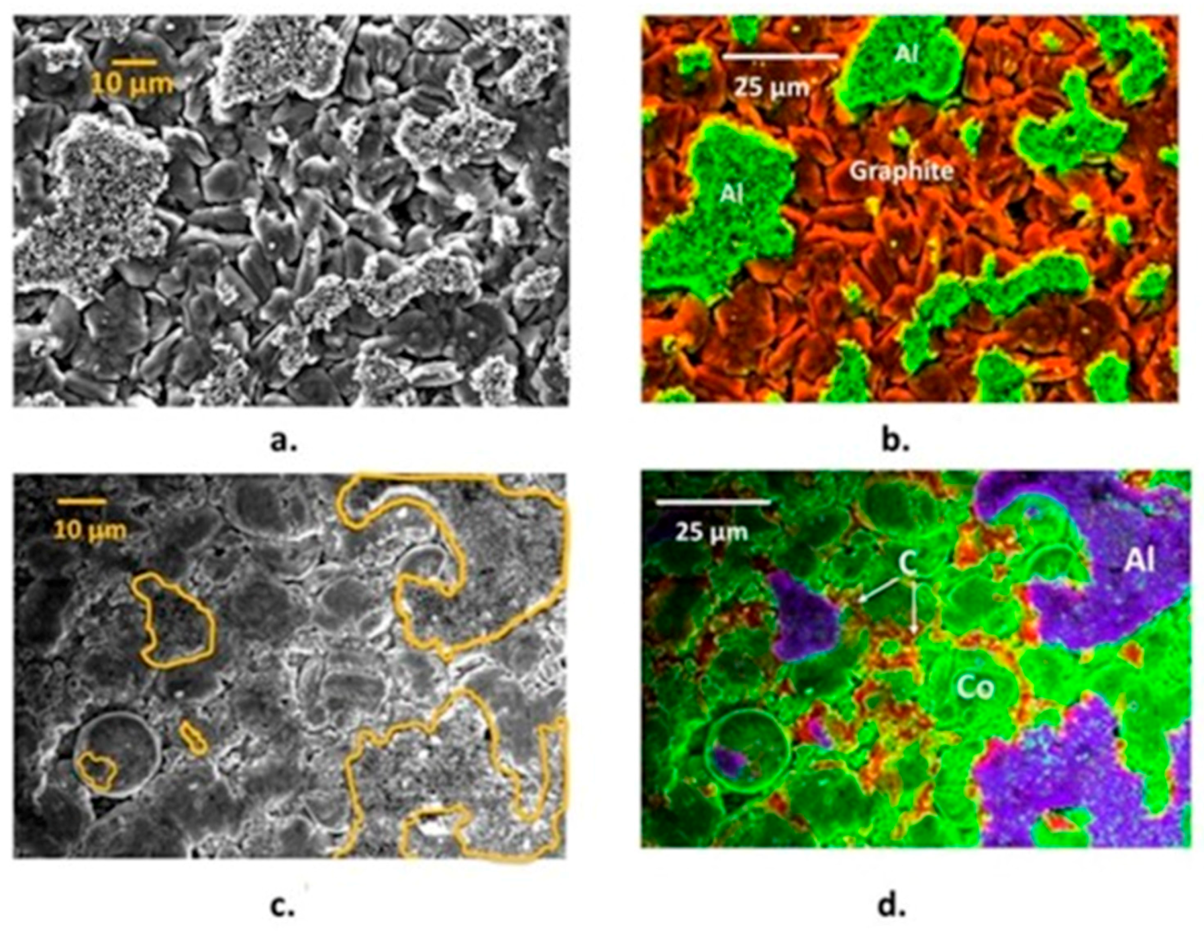
Conversely, on the cathode electrode there were frequent deposits of a ceramic layer—this is investigated further. There have been no mentions of electrode manufacturing quality concerns or separator coating issues in the previous reports. SEM imaging was carried out on electrodes and pieces of separator material and is depicted in
Figure 4, which shows surface analysis and cross-sectional characterisation. The anode was mainly composed of graphite and the cathode was based on lithium cobalt oxide (LiCoO
2).
The separator is a critical component in a battery cell and is a porous polymer membrane used to create an electrically non-conducting physical barrier between the anode and cathode.
Mechanical failure of this component can result in catastrophic failure of the cell and often occurs from puncture or thermal shrinkage of the membrane [
24]. Separators have a complex anisotropic structure and can be susceptible to softening effects by the organic electrolyte solvents [
25].
Such interactions can be characterised by calculation of the Flory–Huggins interaction parameters when the polymer identity and electrolyte solvent composition is known. Commonly used separators are based on multiple layers to provide mechanical resilience and a thermal shutdown mechanism for additional safety. The polymer portion of the Samsung separator is a ceramic coated monolayer and was less than 5 µm in thickness with a double-sided covering of Al
2O
3 of around 1 µm thickness. Other commercially available separators such as Celgard 2325 trilayer polyolefin separators (polypropylene—polyethylene-polypropylene), are over four times the thickness of this at 25 µm, and quote product thickness ranges of 12–40 µm [
26]. Multi-layer polyolefins can be manufactured with a shutdown function and used as a fail-safe component in batteries. However, reports of extremely low wettability with liquid electrolytes have limited its further application in energy storage systems for electric vehicles [
27,
28]. Ceramic coatings have successfully demonstrated resistance to thermal shrinkage in batteries in operating temperature ranges of 110–200 °C for 30 min [
29].
On disassembly of the cell and subsequent unravelling of the components, there were areas of separator that had small sections of electrode coating adhered to them. A thin Al
2O
3 coating is evident on the polymer separator and had becomed delaminated in parts—as can be supported by the ceramic fragments found on the electrode surfaces in
Figure 4. This was apparent during the disassembly of the pouch cell with electrode patches adherent to some areas near the edges of the separator, suggesting more mechanical stress exposure in these areas. From the SEM images below, the ceramic material phases are identified as being aluminium oxide from the adjacent EDS chemical maps. The electrode active materials were found to be graphite and lithium cobalt oxide for the anode and cathode respectively (as expected). The particle size range is very broad in the cathode allowing for increased packing density of the active material and thus higher capacity.
2.3. Characterisation of Welded Joints in Battery Tabs
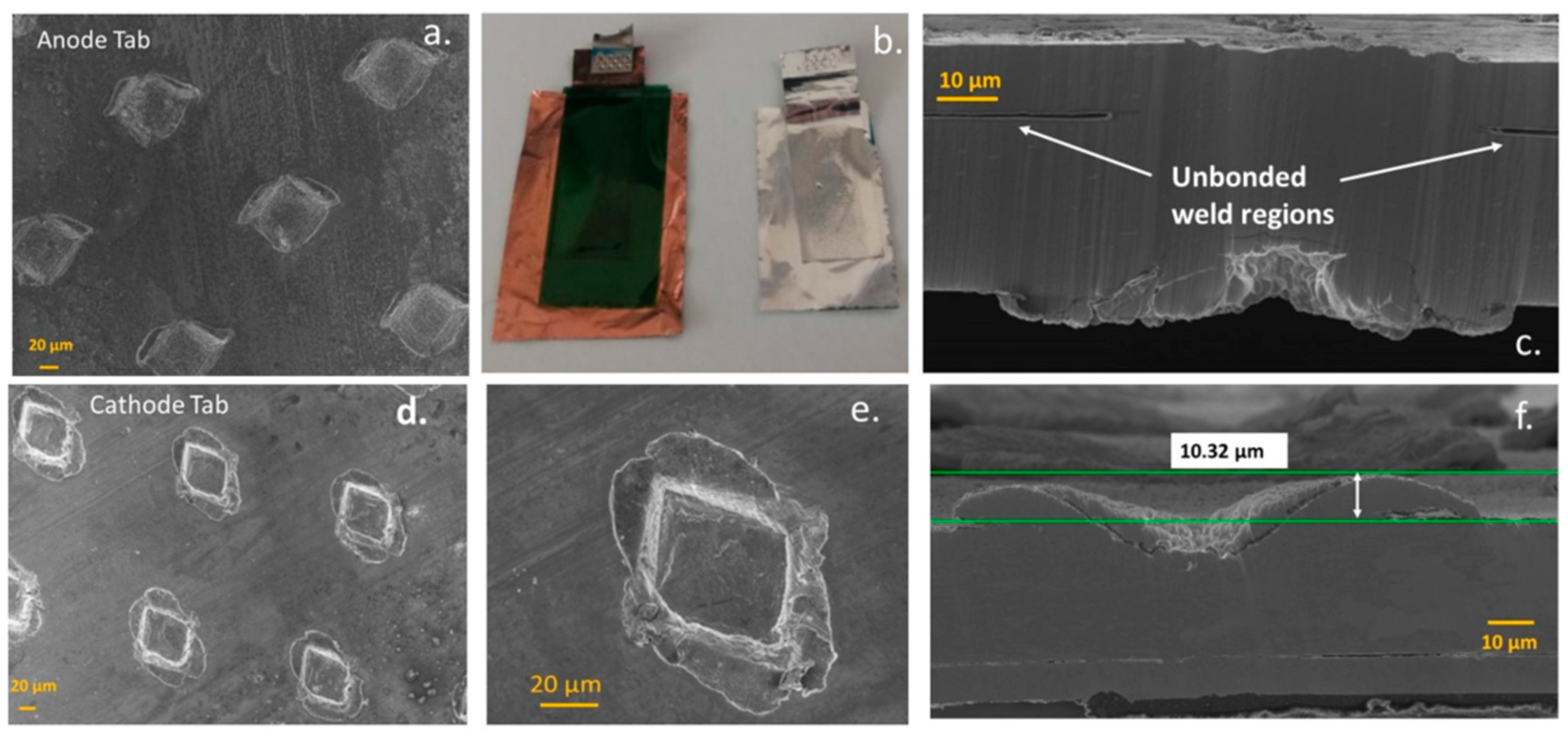
Figure 5 shows SEM images of the anode and cathode welded tab regions that transport current (charge) to the battery electrodes. This is typically used because conventional fusion welding processes (such as resistance spot welding and laser welding) are faced with challenges in joining multiple sheets of highly conductive, dissimilar materials over large areas [
30]. The fusing together of cell current collectors and tabs achieved by ultrasonic welding uses high-frequency energy ≥20 kHz to generate oscillating shears at the interface between a sonotrode and metal sheets. This produces solid-state bonds between the sheets clamped under pressure in a period of time less than a second [
31]. Thus, the solid-state mechanism of the ultrasonic process is better suited to generating weld joints with higher integrity.
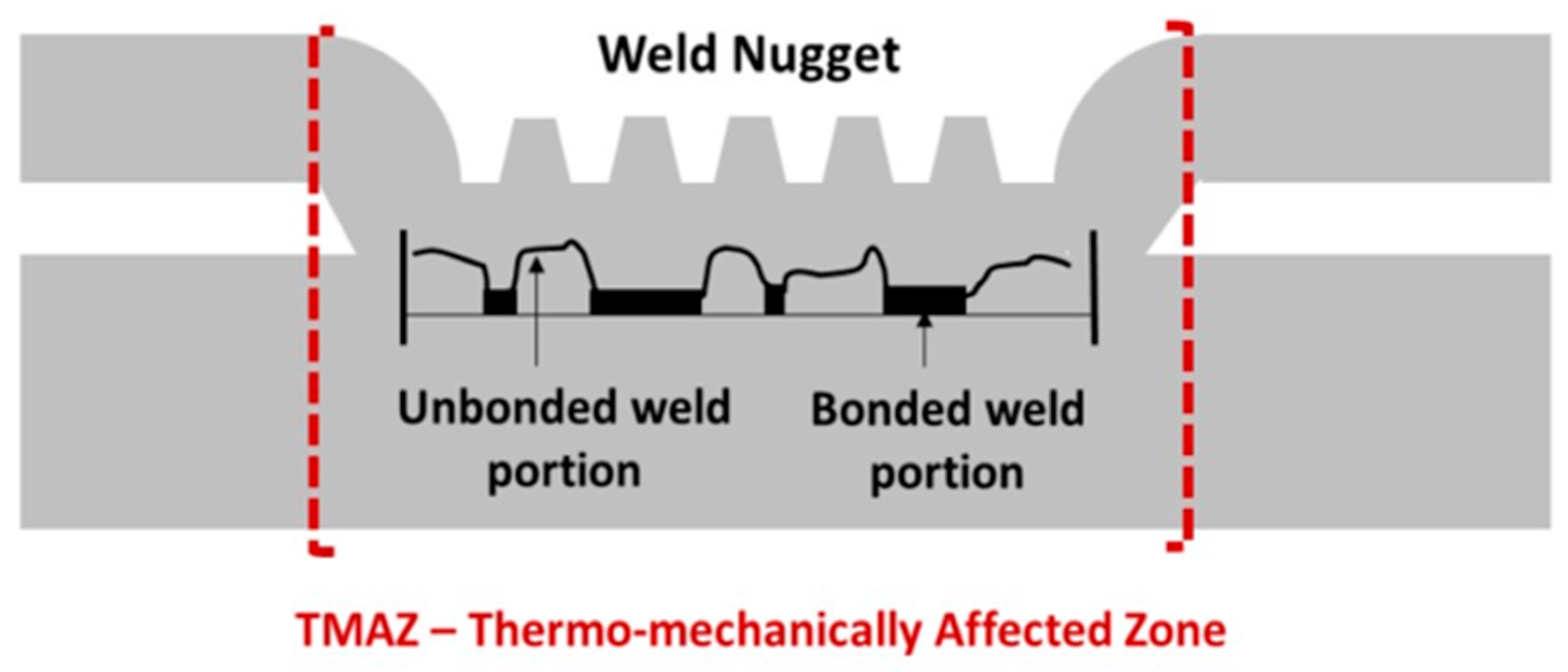
Evident within this type of welding is material flow, whereby excessive plastic deformation can thin and negatively affect the weld quality [
30]. This can result in pieces of material from the thermomechanically affected zone (TMAZ), becoming detached and the weld bond being discontinuous. Cells from Manufacturer B were reported to have sharp protrusions in the welded tab region of the cathode, in the region of the thermomechanical affected zone—see
Figure 6 for a description of key attributes in ultrasonic welds. UL and Exponent released independent reports of their testing on the Note 7 and reported internal cell faulting between the positive electrode tab welding defects and the anode copper foil directly opposite the defective welds—depicted in
Figure 7 [
32]. The figure shows sharp and relatively tall welding defect features and the report suggested a short circuit occurred between the weld defect features on the positive tab and the copper of the negative electrode, resulting in thermal runaway at high states of charge [
32].
The weld areas in the cathode tab section characterised in this study did not appear as sharp protrusions, however our sample size was limited and such failure, if present, would be expected only on a statistically small proportion of cells. We did however detect areas of unbonded weld regions and one of the assessment criteria of weld quality is correlated to the joint characteristics. An ultrasonic metal weld with good weld quality should have dense and continuous interfacial bonds [
30].
The quality and reliability of Li-ion battery tabs is of significant importance especially as batteries are becoming increasingly energetic. A battery tab joint can cause the failure of an entire battery pack if it yields during operation [
33].
3. Materials and Methods
3.1. Electrochemical Characterisation
The charge–discharge parameters were first characterised on the phone in the as-received condition. The cell voltage was around 1.5 V and the cell was rated as 4.4 V maximum. The initial electrochemical characterisation test used a 0.4 amp charge current, applied until the cell reached 4.0 V. No unusual cell behaviour was observed during this first charge.
3.2. Charging Limitation From “Safety Software Patch”
Our investigations were conducted using a Samsung Galaxy Note 7 phone, bought in the open market shortly after the announced product recall. Samsung launched an over-the-air safety software patch in Sept 2016 which limited the extent to which the phone could be charged, and encouraged owners to submit their devices for recall. This was set to 2450 mAh; 70% of its 3500 mAh capacity, and reduced further to 30% capacity (1050 mAh) in December 2016. To prevent this software from affecting our experiments, the phone was housed in a makeshift Faraday cage during initial operation.
3.3. X-ray Computed Tomography
The method firstly analysed the region of interest (ROI) inside the whole sample without dismantling the device, scanning both the uncharged and partially charged battery. The tomography scanners used for this analysis were: X-Tek X-H 225/320 LC (Nikon Metrology, Derby, UK) using CT reconstruction software CT Pro 4.3 (Nikon Metrology, UK) and inspection software VG Studio Max 2.2 (Volume Graphic GmbH). The phone was scanned twice: (i) with the battery discharged; and (ii) with the battery partially charged. The device was positioned consistently to maximise magnification and reduce potential artefacts.
In order to obtain a satisfactory resolution, the device was scanned in two phases—‘Top and Bottom’ and stitched together using a VG Studio Max Best Fit algorithm. Conditions for the top and bottom scans were the same with the individual scans of the battery partially charged having slightly different settings to provide optimum results. A fixture was used in all of the scans to ensure the position of the devise and avoid micro movement during the 360 degrees rotation. The series of variables selected are based on the scanned material, the capabilities of the CT system and the required resolution. The settings and the positioning of the part was selected for maximum magnification resulting in a voxel size and resolution of 52 μm. Materials with noticeably different atomic masses (density) create beam hardening and in order to reduce the error a hardening reduction algorithm was applied.
4. Conclusions
The primary purpose of our activity was to develop and combine a suite of forensic investigation techniques to detect and characterise failure modes in LIBs. We analysed key components within the battery from the Galaxy Note 7, as a topical example, to validate the company’s and the press release findings, but also to gain deeper structural insight into the most likely routes to the incidences. From the tomography scans around the edges of the battery it appears that the cell which we analysed was derived from Manufacturer A: Samsung SDI. Thermal measurements of the cell under charge and discharge showed temperature differentials within the cell which are within expected ranges, and gave no evidence that thermal design was a contributory factor. Our findings corroborate several of the features reported to be the cause for recall, but in addition, use of forensic disassembly and microscopy reveals electrode damage in tightly folded areas, and a weak interfacial bonding of the ceramic layer on the separator as being potential contributory factors.
X-ray tomography confirmed reported findings of the upper corner deformation and compression of the battery contents, leaving minimal volume within the pouch using this type of cell design. Forensic disassembly revealed electrode coating damage in edge and fold regions that were subjected to almost 360° bending. Such localised defects can induce local lithium deposition and dendrite growth, and the plating of lithium could trigger a short circuit through penetration of a thin separator (with lower levels of tensile resilience compared with other commercially used thicker films). This is especially the case in areas where delamination of the ceramic coating had occurred, which were quite frequent over the areas examined. That the ceramic coating became detached during disassembly (following minimal cycling) suggests a weak bonding to the polymer and low interfacial integrity. That the ceramic adheres in some places to the electrode, and in others to the separator, may be significant. For instance, if these layers were to experience micro-slip relative to each other, as the cell expands and contracts due to electrical and thermal cycling, this could result in areas of separator devoid of ceramic coating. Additionally, there would be a build-up of the ceramic coating thickness on others, increasing mechanical pressure on the separator. This may manifest itself during assembly or in use.
Overall, it is clear that the industrial push for increasing energy density of batteries to allow more powerful phones to operate for acceptable periods between charging is resulting in engineering compromises to cell design and component specification which have the potential to deliver such advances at the expense of safety. Industrial actors such as Samsung take this responsibility extremely seriously and devise test and development methods to control such risks to acceptable levels. The body of this work demonstrates the value of combining X-ray tomography, forensic disassembly, and microscopy to elucidate failure pathways in support of such test and development methods. Further work by the authors is planned to investigate further combination with techniques addressing localised electrochemical characterisation and thermo-mechanical loading.
Author Contributions
Melanie. J. Loveridge was the lead author of the article with editing contributions from David Greenwood, Mark Ellis, Mark. A. Williams and Rohit Bhagat. Experimental contributions were carried out by: Tazdin Amietszajew, Nadia Kourra, Ronny Genieser, Guillaume Remy, Mark Amor-Segan, Yue Guo and Anup Barai.
Conflicts of Interest
The authors declare no conflict of interest.
References
- Jacoby, M. Safer Lithium-Ion Batteries. Chem. Eng. News Arch. 2013, 91, 33–37. [Google Scholar]
- Kolly, B.J.; Panagiotou, M.J.; Czech, B.A. The Investigation of a Lithium-Ion Battery Fire Onboard a Boeing 787 by the US National Transportation Safety Board; Safety Research Corporation of America: Dothan, AL, USA, 2013; pp. 1–18. [Google Scholar]
- Christman, J. The case of the burning laptops. J. Case Stud. 2012, 30, 88–97. [Google Scholar]
- National Transportation Safety Board. Aircraft Incident Report: Auxiliary Power Unit Battery Fire, Japan Airlines Being 787-8, JA828j, NTSB/AIR-14/01; National Transportation Safety Board: Washington, DC, USA, 2013; pp. 1–95.
- Rourke, J.O.; Carrillo, A.; Harville, L.; Portilla, D.; Rourke, J.S.O. The Boeing Company: The Grounding of the 787 Dreamliner. J. Organ. Behav. Educ. 2015, 8, 1–12. [Google Scholar]
- Warren, S. Computed Tomography Specialist’s Factual Report; Office of Aviation Safety: Washington, DC, USA, 2013; pp. 1–112.
- Norihiro, G. Emergency Evacuation Using Slides All Nippon Airways Co., Ltd. Boeing 787-8, JA804A, Takamatsu AirportJTSB; Aircraft Serious Incident Investigation Report; Japan Transport Safety Board: Chiyoda, Tokyo, 2014.
- Finegan, D.P.; Scheel, M.; Robinson, J.B.; Tjaden, B.; Hunt, I.; Mason, T.J.; Millichamp, J.; Michiel, M.D.; Offer, G.J.; Hinds, G. Lithium-Ion Batteries During Thermal Runaway. Nat. Commun. 2015, 6, 1–10. [Google Scholar] [CrossRef] [PubMed]
- Lopez, C.F.; Jeevarajan, J.A.; Mukherjee, P.P. Charaterisation of Lithium-Ion Battery Thermal Abuse Behaviour Using Experimental and Computational Analysis. J. Electrochem. Soc. 2015, 162, A2163–A2173. [Google Scholar] [CrossRef]
- Xu, F.; He, H.; Dun, C.; Liu, Y.; Wang, M.; Liu, Q.; Ren, Y.; Xie, J. Failure Investigation of LiFePO4 Cells under Overcharge Conditions. ECS Trans. 2012, 41, 1–12. [Google Scholar] [CrossRef]
- Liu, J.; Wang, Z.; Gong, J.; Liu, K.; Wang, H.; Guo, L. Experimental Study of Thermal Runaway Process of 18650 Lithium-Ion Battery. Materials 2017, 10, 230. [Google Scholar] [CrossRef] [PubMed]
- Spotnitz, R.; Franklin, J. Abuse behaviour of lithium-ion cells. J. Power Sources 2003, 113, 81–100. [Google Scholar] [CrossRef]
- Wang, Q.; Ping, P.; Zhao, X.; Chu, G.; Sun, J.; Chen, C. Thermal runaway caused fire and explosion of lithium ion battery. J. Power Sources 2012, 208, 210–224. [Google Scholar] [CrossRef]
- Hewson, J.C.; Domino, S.P. Thermal runaway of lithium-ion batteries and hazards of abnormal thermal environments. In Proceedings of the 9th U.S. National Combustion Meeting, Cincinnati, OH, USA, 17–20 May 2015; pp. 1–9. [Google Scholar]
- Nedjalkov, A.; Meyer, J.; Köhring, M.; Doering, A.; Angelmahr, M.; Dahle, S.; Sander, A.; Fischer, A. Wolfgang Schade. Toxic Gas Emissions from Damaged Lithium Ion Batteries—Analysis and Safety Enhancement Solution. Batteries 2016, 2. [Google Scholar] [CrossRef]
- Jiang, J.; Dahn, J.R. Effects of particle size and electrolyte salt on the thermal stability of Li0.5CoO2. Electrochim. Acta 2004, 49, 2661–2666. [Google Scholar] [CrossRef]
- Doh, C.-H.; Veluchamy, A. Thermo-Chemical Process Associated with Lithium Cobalt Oxide Cathode in Lithium-Ion Batteries, Lithium-ion Batteries, 1st ed.; Park, C.R., Ed.; InTech: Rijeka, Croatia, 1987; pp. 35–57. [Google Scholar]
- Julien, C.M.; Mauger, A.; Zaghib, K.; Groult, H. Comparative Issues of Cathode Materials for Li-Ion Batteries. Inorganics 2014, 2, 132–154. [Google Scholar] [CrossRef]
- Sun, F.; Moroni, R.; Dong, K.; Marko, H.; Zhou, D.; Hilger, A. Study of the Mechanisms of Internal Short Circuit in a Li-Li Cell by Synchrotron X-ray Phase Contrast Tomography. ACS Energy Lett. 2017, 26, 94–104. [Google Scholar] [CrossRef]
- Dunn, R.P. Flame Retardant Incorporation into Lithium-Ion Batteries. Ph.D. Thesis, University of Rhode Island, Kingston, RI, USA, 2013. [Google Scholar]
- Reuters. Note 7 Fiasco Could Burn a $17 Billion Hole Samsung Accounts. Available online: https://www.reuters.com/article/us-samsung-elec-smartphones-costs/note-7-fiasco-could-burn-a-17-billion-hole-in-samsung-accounts-idUSKCN12B0FX (accessed on 20 November 2016).
- Jesudas, S. Samsung Electronics Anounces Cause of Galaxy Note 7 Incidents in Press Conference, Press Release. Available online: https://news.samsung.com/global/samsung-electronics-announces-cause-of-galaxy-note7-incidents-in-press-conference (accessed on 23 Janary 2017).
- White, K. Samsung Recall Support Note7 Investigation—Root Cause Analysis, Exponent Press Release. Available online: https://www.exponent.com/newsevents/announcements/2017/01/samsung-n7-press-conf (accessed on 25 January 2017).
- Cannarella, J.; Liu, X.; Leng, C.Z.; Sinko, P.D.; Gennady, Y.; Arnold, C.B. Mechanical Properties of a Battery Separator under Compression and Tension. J. Electrochem. Soc. 2014, 161, F3117–F3122. [Google Scholar] [CrossRef]
- Gor, G.Y.; Cannarella, J.; Leng, C.Z.; Vishnyakov, A.; Arnold, C.B. Swelling and softening of lithium-ion battery separators in electrolyte solvents. J. Power Sources 2015, 294, 167–172. [Google Scholar]
- Arora, P.; Zhang, Z. Battery Separators. Chem. Rev. 2004, 104, 4419–4462. [Google Scholar] [CrossRef] [PubMed]
- Choi, J.; Heum, S.; Kim, D. Enhancement of thermal stability and cycling performance in lithium-ion cells through the use of ceramics-coated separators. J. Power Sources 2010, 195, 6192–6196. [Google Scholar] [CrossRef]
- Woo, J.; Zhang, Z.; Rago, N.L.D.; Lu, W.; Amine, K. A high performance separator with improved thermal stability for Li-ion batteries. Polym. J. Mater. Chem. A 2013, 1, 8538–8540. [Google Scholar] [CrossRef]
- Shi, C.; Dai, J.; Li, C.; Shen, X.; Peng, L.; Zhang, P.; Wu, D.; Sun, D.; Zhao, J. A Modified Ceramic-Coating Separator with High-Temperature Stability for Lithium-ion Battery. Polymers 2017, 9, 159. [Google Scholar] [CrossRef]
- Lee, S.S.; Kim, T.H.; Hu, S.J.; Cai, W.W.; Abell, J.A. Characterisation of Joint Quality in Ultrasonic Welding of Battery Tabs. J. Manuf. Sci. Eng. 2017, 135, 1–13. [Google Scholar]
- Kang, B.; Cai, W.; Tan, C.-A. Dynamic Response of Battery Tabs under Ultrasonic Welding. ASME J. Manuf. Sci. Eng. 2012, 136. [Google Scholar] [CrossRef]
- Humrick, M. Samsung Reveals Root Cause of Galaxy Note 7 Battery Fires. Available online: https://www.anandtech.com/show/11060/samsung-reveals-root-cause-of-galaxy-note7-battery-fires (accessed on 23 January 2017).
- Zhao, N.; Li, W. Fatigue Life Prediction Model For Ultrasonically Welded Battery Tab Joints. J. Manuf. Sci. Eng. 2014, 136. [Google Scholar] [CrossRef]
© 2018 by the authors. Licensee MDPI, Basel, Switzerland. This article is an open access article distributed under the terms and conditions of the Creative Commons Attribution (CC BY) license (http://creativecommons.org/licenses/by/4.0/).

 ,
, 