Flexible and Lightweight Lithium-Ion Batteries Based on Cellulose Nanofibrils and Carbon Fibers


1
Applied Electrochemistry, Department of Chemical Engineering, KTH Royal Institute of Technology, SE-100 44 Stockholm, Sweden
2
Wallenberg Wood Science Center, KTH Royal Institute of Technology, SE-100 44 Stockholm, Sweden
*
Author to whom correspondence should be addressed.
Batteries 2018, 4(2), 17; https://doi.org/10.3390/batteries4020017
Submission received: 11 January 2018
/
Revised: 20 March 2018
/
Accepted: 26 March 2018
/
Published: 2 April 2018
(This article belongs to the Special Issue Innovations in Paper-based Flexible Batteries)
Abstract
:Flexible, low-weight electrodes with integrated current collectors based on chopped polyacrylonitrile carbon fibers (CF) were produced using an easy, aqueous fabrication process, where only 4 wt% of TEMPO-oxidized cellulose nanofibrils (CNF) were used as the binder. A flexible full cell was assembled based on a LiFePO4 (LFP) positive electrode with a CF current collector and a current collector-free CF negative electrode. The cell exhibited a stable specific capacity of 121 mAh g−1 based on the LFP weight. The CF in the negative electrode acted simultaneously as active material and current collector, which has a significant positive impact on energy density. Stable specific capacities of the CF/CNF negative electrode of 267 mAh g−1 at 0.1 C and 150 mAh g−1 at 1 C are demonstrated. The LFP/CNF with CF/CNF, as the current collector positive electrode (LFP-CF), exhibited a good rate performance with a capacity of ~150 mAh g−1 at 0.1 C and 133 mAh g−1 at 1 C. The polarization of the LFP-CF electrode was similar to that of a commercial Quallion LFP electrode, while much lower compared to a flexible LFP/CNF electrode with Al foil as the current collector. This is ascribed to good contact between the CF and the active material.
1. Introduction
The demand for flexible electronic devices, such as flexible displays [1], flexible radio frequency identification (RFID) tags [2], wearable electronics and implantable devices [3,4], is rapidly growing. Flexible lithium-ion batteries (LIB) have gained considerable attention as a promising energy storage solution for such applications [5,6,7,8,9,10,11,12,13]. Metal foils of Al or Cu are the conventional current collectors used in LIB, but are not suitable for flexible batteries, as loss of contact between the active material and the foil is very likely to occur during repeated bending [14]. The high density of the metal foils also results in a low specific energy density for LIB. Chu et al. reported the use of a thin copper nanowire foil as a current collector to enhance the specific energy density for LIB [15]. Films based on lightweight materials, such as carbon nanotubes (CNT) and graphene, have been widely investigated as current collectors for flexible LIB [5,7,14,16]. Yoon et al. reported that carbon nanotube films as negative electrodes for flexible LIB had high flexibility, good mechanical properties, and high electrical conductivity [17]. However, these nanostructured current collectors and carbon-based materials are relatively expensive and require complex preparation processes. Carbon fibers (CF) have been investigated as an alternative current collector for LIB due to their high conductivity and good mechanical properties [18,19,20]. Furthermore, polyacrylonitrile (PAN)-based CF can be used as active material for the negative electrode in LIB [21,22,23], and Kjell et al. reported that CF can be used as both active material and current collector in LIB [22]. Jabbour et al. showed that carbon/cellulose fibers composite sheets could be used as current collector-free negative electrodes [19].
The conventional binder material for the electrodes in LIB is polyvinylidene fluoride (PVDF), which is relatively expensive and needs to dissolve in a toxic solvent, such as N-methyl-pyrrolidone (NMP). In addition, using PVDF as a binder limits the flexibility of the electrodes. Cellulose-based materials, including cellulose fibers, or cellulose nanofibrils (CNF) produced from wood in a sustainable way have gained considerable interest as a promising alternative binder for flexible paper electrodes due to excellent mechanical properties, low cost, and environmental friendliness [9,11,24,25].
In our previous work, we have shown that flexible electrodes can be fabricated using a low amount (4 wt%) of CNF [24]. In the present work we have developed this concept further by incorporating lightweight CF current collectors and producing a full battery cell with a high degree of carbon based materials: CF current collectors; CF as active negative electrode material; and CNF as binder. The low amount of binder and the light weight of the CF increase the energy density of the LIB. Electrochemical properties and morphologies for both negative and positive electrodes were investigated from electrochemical charge-discharge characteristics, as well as scanning electron microscopy (SEM), X-ray diffraction (XRD), and Brunauer-Emmet-Teller (BET) measurements. Furthermore, this work demonstrates a facile fabrication process of lightweight and flexible electrodes with integrated current collectors, which is very beneficial from environmental and industrial perspectives.
2. Results and Discussion
The XRD spectrum for the IMS65 CF, chopped with the 60 mesh (see Materials and Methods) by a Thomas Wiley mini-mill cutting mill, is shown in Figure 1. The peak around 2θ = 26° corresponds to the (002) reflection for graphite, while the peaks around 2θ = 43° can be attributed to a superposition of the graphitic (100) reflection and the (101) reflection from the disordered CF [26]. The interlayer spacing, d002, and the crystallite sizes, Lc, can be calculated with the Bragg and Scherrer formulae, respectively, to be d002 = 3.50 Å and Lc = 24.3 Å. For graphite typical values are d002 = 3.35 Å and Lc ≈ 400 Å. The relatively large interlayer spacing and the low values of Lc for the CF indicate a largely disordered and amorphous structure with small crystal sizes, which is consistent with previous work [23]. The BET surface area for the chopped CF is found to be 0.65 m2 g−1, slightly higher than the unchopped CF measured previously (0.42 m2 g−1 [23]), which is due to the extra area from the chopped cross-sections. It is still very low, however, which is beneficial for a small solid-electrolyte interface (SEI)-layer and stable cycling performance. A summary of the crystallite parameters and the BET surface area is seen in Table 1.
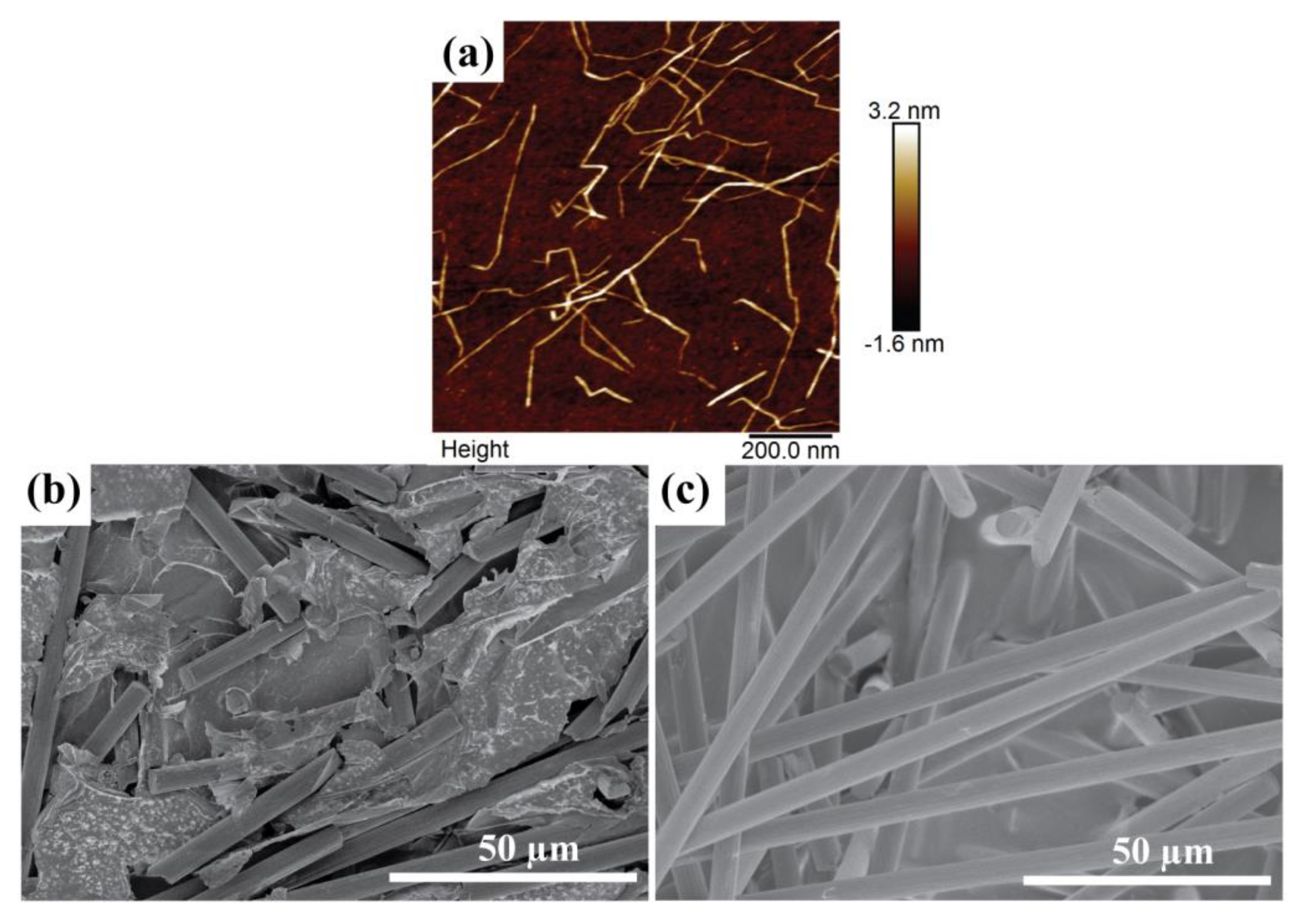
An atomic force microscope (AFM) height image of the CNF is presented in Figure 2a. It is seen that every fibril is finely dispersed. The width and length of the fibrils are approximately 2–3.5 nm and 0.1–1 µm, respectively. Figure 2b,c presents SEM images of the CF/CNF films, illustrating the different morphologies of the two sides of each layer. The bottom side (towards the filter) after the filtration process is smooth with densely packed CF bound by CNF sheets (Figure 2b). The top side (Figure 2c) is rough, with CF more loosely packed and sticking out from the CNF sheets—note though that the CF adhere strongly to the electrodes so CNF also works well as a binder for this part of the film. Likely the light weight of CF causes them to easily float over the film surface during the filtration.
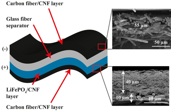
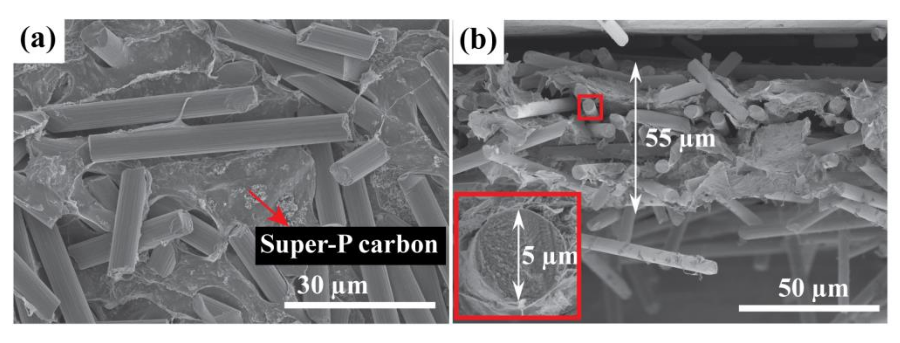
In order to increase the conductivity of the CF/CNF electrodes, 2 wt% Super-P carbon (SPC) was added to their composition. Figure 3 shows SEM images of surfaces and cross sections of the CF/SPC/CNF electrodes. The CF are homogenously dispersed by CNF sheets, and the SPC particles are relatively uniformly mixed into the CNF sheets, as seen in Figure 3a. Some agglomeration is seen, which is normal for nano-sized particles. The thickness of the CF/SPC/CNF films is approximately 55 µm as shown in the cross sectional image in Figure 3b. The inset in Figure 3b shows that the diameter of a CF is ~5 µm, which is consistent with the manufacturer’s data. Each CF is wrapped by CNF sheets, which is in agreement with the surface SEM images, and the overall morphologies of the electrodes seem uniform.
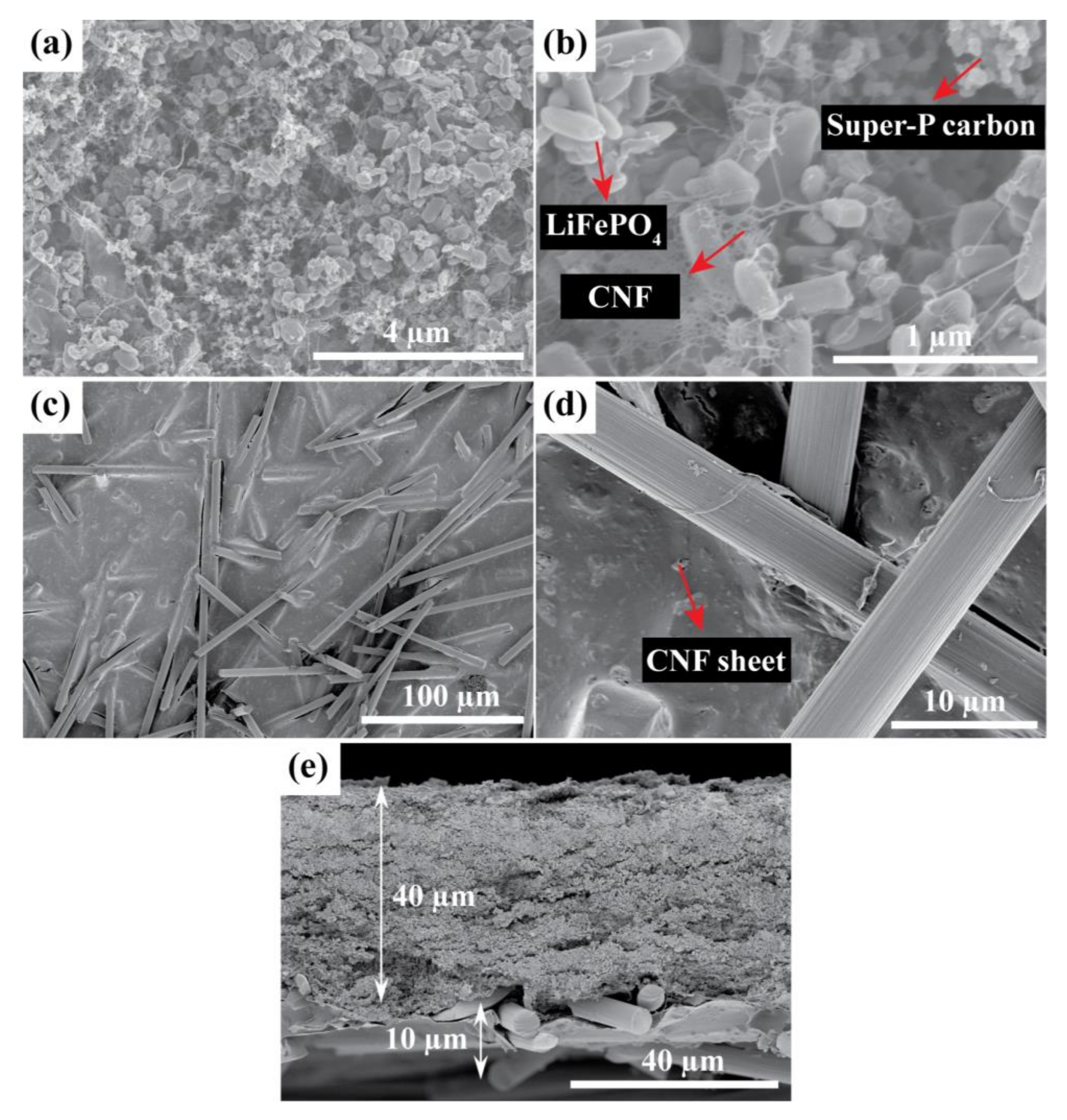
Figure 4 shows SEM images of the LFP/SPC/CNF electrode with integrated CF/SPC as the current collector (LFP-CF). The LFP and SPC nanoparticles are uniformly dispersed by the CNF web, as shown in Figure 4a,b. The CF are relatively homogenously distributed and surrounded by CNF sheets, as seen in Figure 4c,d. The cross-sectional SEM image in Figure 4e shows that the thickness of the LFP and CF current collector layers are approximately 40 and 10 µm, respectively.
The mechanical properties and conductivities of the LFP-CF and CF/SPC/CNF electrodes are shown in Table 2. Both exhibit similar strength and modulus since they both consist of ~4 wt% CNF as binder, which is the main contributor to the mechanical properties. Their ultimate tensile strengths are ~2 MPa. The Young’s modulus for the CF/SPC/CNF negative electrode is ~225 MPa, which is slightly higher than that of the LFP-CF positive electrode (~201 MPa). This could be ascribed to the higher concentration of CF, with advantageous mechanical properties, in the negative electrodes. The tensile strain at break for the CF/SPC/CNF is lower than that of the LFP-CF electrode, which is probably caused by the stiffness of the CF. The conductivity of the CF/SPC/CNF is 143 S m−1; the high value is ascribed to the high CF content in the electrode (94 wt%). The conductivity of the LFP-CF electrode is 95 S m−1. The lower value compared to the CF/SPC/CNF electrode is ascribed to the relatively lower amount of CF. Since the rate performance is good (see below), these are sufficient conductivities for usage without additional current collectors. The conductivities can be compared to our previous work, where an LFP/SPC/CNF electrode exhibited a conductivity of around 0.1–1 S m−1, depending on the component ratios [24]. Even with as much as 11 wt% SPC, the conductivity was no higher than 1.14 S m−1. The much higher value clearly shows the effect of integrating a CF current collector film.
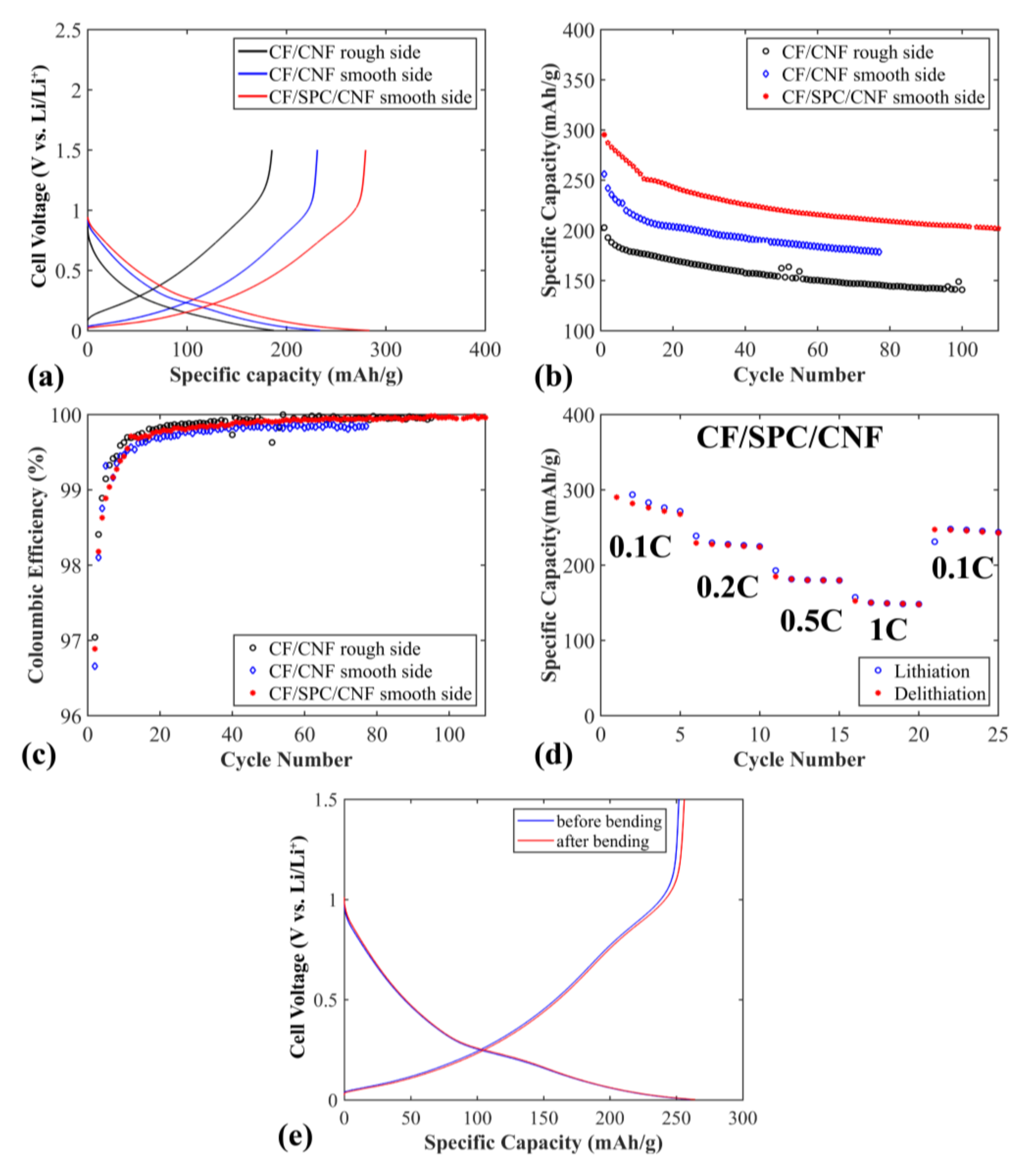
Figure 5 shows the electrochemical properties of the flexible CF/CNF and CF/SPC/CNF negative electrodes. The sloping voltage profile is typical for disordered carbon materials, where a distribution of Li+ insertion sites generates a distribution of the chemical potentials [27]. As shown in Figure 5a, the electrode shows a higher specific capacity and lower polarization when the smooth side of a CF/CNF sheet is oriented towards the separator, compared to when the rough side of the CF/CNF films is pressed against the separator. This illustrates that the smooth side of the CF/CNF electrode, with densely-packed CF, seems to be beneficial for Li+ transfer while the rough side is beneficial as the current collector side, as it contains less of the insulating CNF. When 2 wt% SPC is added to CF/CNF, increasing the conductivity between the CF, even better electrochemical properties are achieved, including higher specific capacity and lower polarization (see Figure 5a,b). The initial specific capacity of the electrode is ~300 mAh g−1, but drops rapidly to ~250 mAh g−1 after 13 cycles, which is ascribed to the solid electrolyte interface (SEI) layer stabilization for CF electrodes [23]. A slightly lower specific capacity is observed for these flexible electrodes compared to free standing, unchopped, electrodes of the same type of CF in previous work [23] (300 mAh g−1 versus 358 mAh g−1). This is to be expected, since the fibers are chopped here which, in addition to the added CNF binder, lowers the conductivity of the electrodes (the conductivity of the non-chopped carbon fibers is 694 S cm−1). The capacity retention is ~83% after 13 cycles, which is similar to previous studies [23]. The electrode maintains a relatively stable specific capacity for the following cycles, with a specific capacity retention of ~80% after 110 cycles. The coulombic efficiency of the electrodes is shown in Figure 5c. After 13 cycles, the coulombic efficiency of the CF/SPC/CNF electrode reaches 99.71% and increases to over 99.90% after 41 cycles. This illustrates that the CF/SPC/CNF electrode exhibits a good cycling stability with a low amount of side reactions.
Rate capabilities of the CF/SPC/CNF electrode are shown in Figure 5d. The electrodes exhibit relatively stable capacities for all C-rates, except for a drop during the first five cycles at 0.1 C. This is caused by the SEI layer stabilization, as well as by Li being trapped in the disordered CF structure, which has been observed previously for PAN-based CF [23]. The specific capacity decreases from ~267 to ~230 mAh g−1 when the current rate increases from 0.1 to 0.2 C due to higher polarization at increased current density. At high currents, 0.5 C and 1 C, the specific capacities of the electrode are ~180 mAh g−1 and ~150 mAh g−1, respectively. The specific capacity at 1 C is higher than that of the CF paper electrode at 0.6 C (~75 mAh g−1) mentioned in the work of Jabbour et al. [19]. This is most probably due to the lower amount of CNF (4 wt%) that was used to prepare our electrode, compared to ~20 wt% cellulose fibers in Jabbour’s work [19]. When the current rate changes back to 0.1 C, the electrode obtains a relatively stable capacity of ~242 mAh g−1, with a capacity retention of 91% compared to the first 0.1 C rate capacity.
Figure 5e presents voltage profiles at 0.1 C for CF/SPC/CNF electrodes before and after 4000 times repeated bending. SEM pictures after bending and consecutive cycling of the same electrode is presented in Figure S1a,b. No significant difference is observed, in either voltage profiles or morphology seen in the SEM, which indicates that the flexibility of the electrode is good, and that the electrochemical properties are unaffected by repeated bending.
Figure 6a shows a comparison between the charge/discharge voltage profiles for flexible LFP electrodes using CF or Al as current collectors (LFP-CF and LFP-Al). At 0.1 C, the electrodes have similar specific capacities, but with a slightly larger charge and discharge overpotential for the electrode with Al as current collector. At 1 C the electrode with CF as current collector exhibits higher specific capacity and lower polarization (101 mV compared to 486 mV) than that of the electrode with an Al current collector. This indicates a significantly lower overall contact resistance when using CF as current collector compared to conventional Al current collectors, likely due to the close interface and good contact between the LFP and CF layers prepared by the filtration process.
To further evaluate the performance of the LFP-CF flexible electrode, a commercial Quallion LFP electrode was cycled. As seen in Figure 6a, at 0.1 C both the Quallion electrode and the LFP-CF electrode reach their maximum specified capacities (170 mAh g−1 and 150 mAh g−1, respectively). The reason for the lower capacity of the LFP-CF compared to the Quallion electrode is that the LFP we use in this work has a specific capacity of ~150 mAh g−1 according to the supplier (170 mAh g−1 theoretical max for LFP). The LFP-CF and the Quallion electrodes show similar polarization behavior. In Figure 6b, EIS Nyquist plots is presented for the three different electrodes. The higher polarization of the LFP-Al electrode is confirmed by a charge-transfer resistance (semicircle diameter) of ~200 Ω cm2 compared to ~50 Ω cm2 for the other electrodes. The LFP-CF electrode has a charge-transfer resistance similar to that of the Quallion electrode.
Figure 6c shows the rate capabilities of the LFP-CF and of the Quallion electrode. The specific capacities of the Quallion electrode are slightly higher overall than those of the LFP-CF electrode at different currents, for the same reason as explained above. The rate capabilities of the LFP-CF are very good, and similar to those of the Quallion electrode. The LFP-CF electrode obtains a specific capacity of ~150 mAh g−1 at 0.1 C. After increasing current rates to 0.2 C and 0.5 C, it delivers a capacity of 147 and 142 mAh g−1, respectively. Even at a high current rate (1 C) the electrode can keep a stable capacity of 133 mAh g−1. After 20 cycles at different current rates, when the current is decreased to 0.1 C again, the electrode regains the full capacity as the first five cycles at 0.1 C (~100% retention).
Figure 6d shows voltage profiles at 0.1 C before and after 4000 times of repeated bending. SEM pictures after bending and cycling is seen in Figure S1c,d. As with the CF/SPC/CNF electrode no large difference is observed in the voltage profiles, except a slightly lower capacity after bending which could be ascribed to local variations of active material distribution in the electrode. The SEM pictures revealed no visible difference in morphology after bending and cycling. It can be concluded that this electrode also has good flexibility, and that the electrochemical performance is maintained after being bent many times.
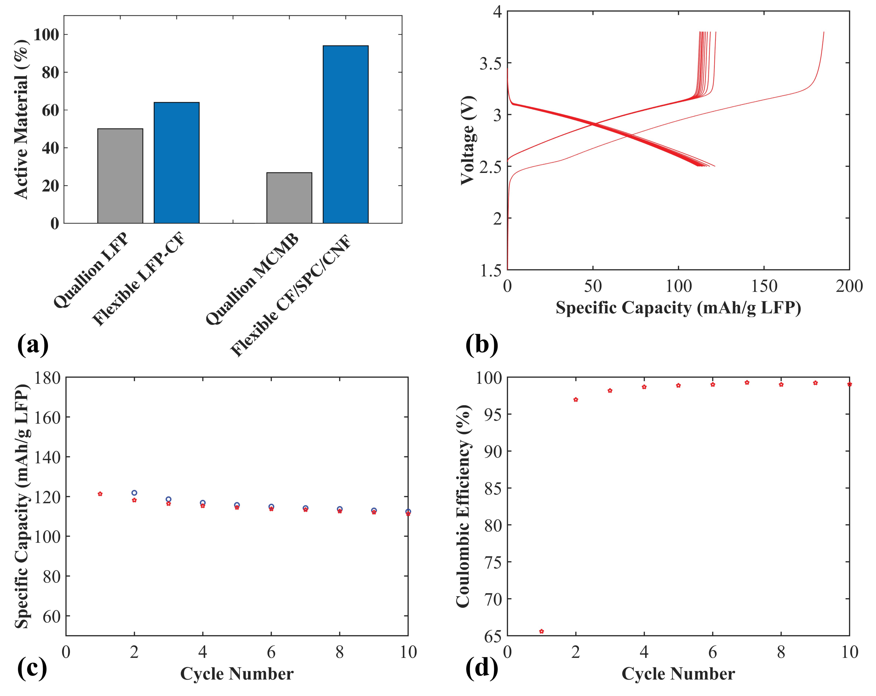
In order to evaluate the weight reduction for both electrodes when using CF as the active material and current collector, compared to conventional electrodes, the active weight percentage was calculated and compared to commercial Quallion electrodes (see Figure 7a). The Quallion positive electrode is LFP based, with 84 wt% active material and a 20 µm Al current collector, with a full electrode thickness of 55 µm. The negative electrode is a graphite meso-carbon microbead (MCMB) electrode with 90 wt% active material and a 10 µm Cu current collector, with a full electrode thickness of 40 µm. When calculating the active material weight percentages for all electrodes in Figure 7a, the weight of the current collectors were included. For the positive LFP-CF flexible electrode (thickness 50 µm), an increase of 28% active material, from 50.1% to 64%, was achieved. For the negative CF/SPC/CNF electrode (thickness 55 µm), a large increase of 250% (from 26.8% to 94%) was achieved. This is because, for the negative electrode, carbon fibers are used as both the active material and the current collector, the Cu current collector in the MCMB electrode makes up much of the total weight. This illustrates a large positive impact on the gravimetric energy density compared to conventional electrodes.
Figure 7b–d shows the electrochemical properties of a full flexible cell with a positive LFP-CF electrode and a negative CF/SPC/CNF electrode. The charge/discharge voltage profiles are shown in Figure 7b. The specific capacity is based on the weight of the LFP. The irreversible discharge capacity of the cell for the first cycle is again likely caused by the SEI layer formation and trapped Li in the CF/SPC/CNF negative electrode, which is observed for the CF/SPC/CNF half-cell in Figure 5. Figure 7c,d show that the full cell obtains an initial specific capacity of ~121 mAh g−1, a 92% capacity retention of the initial capacity after 10 cycles, and a coulombic efficiency of approximately 99%. The gravimetric energy density of the full cell for the initial cycle, based on the total mass of the CF current collectors and electrodes, is ~150 Wh kg−1. The mass of the electrolyte, separator and the package was omitted since pouch cells were used, with an excess of electrolyte and a large 260 µm glass fiber separator in contrast to the lightweight separators normally used in commercial cells. Adding the weight of those components would lower the energy density slightly. However, the values obtained are still in the range of commercial LIB (100–200 Wh kg−1 [28]), which is a high value considering that commercial LIB are highly optimized, with typically double-coated current collectors. This illustrates that the flexible cell can be assembled with a positive flexible electrode using a lightweight CF current collector and a negative electrode based on CF flexible films without any additional current collector. This use of CF is a promising method to significantly raise the energy density and lower the cost of future batteries.
3. Materials and Methods
3.1. Materials
2,2,6,6-tetramethylpiperidine-1-oxyl (TEMPO)-oxidized CNF was synthesized following a procedure reported elsewhere [24,29]. The charge density of the CNF was ~626 µeq g−1. Carbon-coated lithium iron phosphate (LiFePO4 (LFP)) of the type Life Power P2 and SPC were provided by Phosphate Lithium (St-Bruno-de-Montarville, QC, Canada) and Imerys Graphite & Carbon (Bironico, Switzerland). The LFP contains 2–3 wt% carbon and has a specific capacity of ~150 mAh g−1 according to the supplier. The CF used were commercial PAN-based, IMS65 from Toho Tenax (Chiyoda-Ku, Japan). Chopping of the CF was carried out with a Thomas Wiley Mini-Mill Cutting Mill from Thomas Scientific (Swedesboro, NJ, USA) with a Monel metal sieve of 60 mesh. Ethanol 96% and 99.5% were supplied by Solveco (Stockholm, Sweden), dried acetone >99.9% and pentane 99.9% were supplied by Merck KGaA (Darmstadt, Germany) and VWR International AB (Stockholm, Sweden), respectively. All of these solvents were used for solvent exchange as described below. The electrolyte used in the cells was composed of 1 M LiPF6 salt in ethylene carbonate (EC): diethyl carbonate (DEC) 1:1 by weight supplied by Merck KGaA (Darmstadt, Germany). Whatman GF/A glass microfiber papers 260 µm were used as separators, provided by VWR International AB (Stockholm, Sweden). The cycling performance of electrodes with Al foil as current collectors was investigated as a comparison to the CF current collectors. The Al foil had a thickness of 25 µm, and was purchased from Advent Research Materials (Witney, UK). Durapore membrane filters, type 0.22 µm GV, were supplied by Millipore (Burlington, MA, USA). All water used was deionized in a Milli-Q apparatus from Millipore (Stockholm, Sweden). Electrodes supplied by Quallion LLC (Sylmar, CA, USA) were used for reference trials.
3.2. Preparation of Flexible CF Electrodes and LFP-CF Electrodes
A water-based paper-making method was used to prepare the electrodes, as mentioned in previous works [24,30,31]. Four types of electrodes/current collectors were produced and are defined in Table 3, where the different ratios of components used to prepare suspensions for the electrodes/current collectors are also given. First, the components were mixed in water with an Ultra Turrax D 125 Basic disperser from Merck KGaA (Darmstadt, Germany) at 10,000 rpm for 20 min. Then, the suspensions were vacuum-filtered through a Durapore membrane filter. When liquid was no longer observed, solvent exchange was applied by filtration in sequence (50 mL of ethanol 96%, ethanol 99.5%, dried acetone and then pentane). The thickness of the electrodes can easily be controlled by adjusting the amount of suspension used for the filtration. Finally, the flexible electrodes were dried for 1 h at 110 °C in vacuum. Pouch cells were assembled in a glovebox under argon atmosphere (<1 ppm H2O and O2). The pouches were vacuum sealed using a Multivac C70 vacuum sealer from Multivac (Lund, Sweden) with a 3 M thermal bonding film 615 for the current collector exits. See Figure S2 for a picture of a pouch cell used for the full cell. For the positive electrode, the active material was LFP and an LFP/SPC/CNF layer was formed first, and the CF/CNF layer was added on top as a current collector. For the negative electrode, the CF, itself, acted as the active material as well as the current collector (no extra current collector layer was needed); a single layer of CF/CNF or CF/SPC/CNF was manufactured. Four types of cells were assembled: (i) CF/CNF (or CF/SPC/CNF) electrode versus Li metal (negative electrode half-cell); (ii) LFP/SPC/CNF with CF/CNF current collector electrode (LFP-CF) versus Li metal (positive electrode half-cell); (iii) LFP/SPC/CNF with Al foil as current collector electrode (LFP-Al) versus Li metal (positive electrode half-cell); and (iv) CF/SPC/CNF electrode versus LFP-CF electrode (full cell). The size of the electrodes used was around 2 cm2. For the full cell the positive:negative electrode capacity ratio was 1:1.2.
3.3. Material Characterization
XRD measurements were carried out with a Diffractometer D5000 from Siemens (Munich, Germany) with a Cu Kα/Kβ source. A coupled scan between 10° and 70°, a step size of 0.02°, and a dwell time of 6 s was carried out. The BET method was used to measure the specific surface area of the chopped CF and carried out with a Micromeritics ASAP 200 instrument from Micromeritics Instrument Corp. (Norcross, GA, USA) using N2 adsorption at −196 °C. An AFM was used to measure the morphology of the CNF, which was performed using a Multimode 8 scanning probe microscope (Bruker AXS, Santa Barbara, CA, USA) in PeakForce Quantitative Nanomechanical Mapping (QNM) mode using a ScanAsyst-Air cantilever with nominal spring constant of 0.4 N m−1 at a resonant frequency of 70 kHz. The morphologies of the electrodes were studied using a Hitachi S-4800 field emission scanning electron microscope (SEM) from Hitachi (Tokyo, Japan). Tensile tests were performed using an Instron 5944 from Instron (Norwood, MA, USA) mechanical testing system from equipped with a 500 N load cell at 25 °C. For each of the electrodes, five rectangular samples (5–10 mm × 20 mm) were tested with a rate of 10% min−1. To evaluate the flexibility of the electrodes, the same tensile tester was used to repeatedly bend the electrodes. A three-point bending procedure was applied 4000 times at a speed of 18 mm s−1; the distance between the supports was 20 mm, and the depth at the lowest point was 9 mm. See Figure S3 for a picture of the three-point bending loaded with a flexible CF/SPC/CNF sample.
3.4. Electrochemical Measurements
The electrochemical properties of the cells were measured using an in-house constructed high-precision cell cycling setup [24] and a SI 1286 potentiostat from Solartron Analytics (Farnborough, UK). The voltage windows used for the CF electrodes, LFP with CF current collector, and full cells were 0.002–1.5 V, 2.8–4 V, and 2.5–3.8 V, respectively. The specific capacities are defined as capacities divided by the mass of the active material (LFP for the positive electrode and CF for the negative electrode). The electrochemical impedance spectroscopy (EIS) studies of the LFP-CF, LFP-Al, and Quallion electrodes were carried out using a PCI4 G750 potentiostat from Gamry Instruments (Warminster, PA, USA) in a frequency range of 100–0.01 Hz. All of the cells were charged at 0.1 C up to a 10% state of charge (SOC) before the EIS test. The conductivity of the electrodes was measured using an in-house four-probe Van der Pauw setup with four graphite electrodes.
4. Conclusions
We report the successful fabrication of a flexible, lightweight, current collector-free CF negative electrode, and an LFP with carbon fibers as a current collector positive electrode (LFP-CF). The electrodes were produced by an easy aqueous-based paper making process using a low amount of CNF as binder. The conductivities of both electrodes were high enough to be used without additional metallic current collectors, 143 S m−1 for the CF/SPC/CNF negative electrode and 95 S m−1 for the LFP-CF positive electrode. A CF negative electrode versus a LFP-CF positive electrode assembled into a full cell exhibited relatively good electrochemical properties, with a reversible specific capacity of ~121 mAh g−1 cycled at 0.1 C, and a gravimetric energy density of ~150 Wh kg−1. The CF were relatively uniformly bound by CNF sheets, and the electrodes showed good mechanical properties, a Young’s modulus and strength ~225 and ~2 MPa, respectively. A relatively good cycling stability with a coulombic efficiency higher than 99.90%, and a good rate capability were obtained for the CF-based negative electrodes. Flexible positive electrodes with LFP as active material, CF as current collector, and CNF as binder are demonstrated as well. A considerable improvement in the electrochemical performance, including high galvanostatic energy density and low polarization at high current, was obtained for the LFP electrode with CF as the current collector compared to when using an Al current collector. Similar charge-transfer resistance, capacity, capacity retention, and rate performance as for a commercial (Quallion) LFP electrode were achieved for the LFP-CF electrode, which is noteworthy since the commercial electrode is highly optimized. The added benefit of a lower weight of the CF based electrodes is achieved as well, illustrated by an increase in wt% active material based on the combined weight of the current collector and the electrode. A 28% increase is achieved for the LFP-CF electrode, and a 250% increase for the CF/CNF electrode compared to the commercial (Quallion) counterparts. This provides an easier and lower-cost way to prepare electrodes towards lightweight, high energy density, and flexible LIB.
Supplementary Materials
The following are available online at https://www.mdpi.com/2313-0105/4/2/17/s1. Figure S1. SEM images of the flexible electrodes after 4000 times of repeated bending and consecutive cycling: (a) smooth side and; (b) rough side of the CF/SPC/CNF electrode; (c) CF layer; and (d) the LFP layer of the LFP-CF electrode; Figure S2. Picture of a lab-scale pouch full cell with a flexible LFP-CF electrode as positive electrode and a CF/SPC/CNF electrode as negative electrode. Cu and Al foils are only used for contacting the carbon fiber current collectors on the edge and lead current out of the pouch. An oversized pouch and Whatman GF/A glass microfiber paper 260 µm was used as separator; Figure S3. Picture of a CF/SPC/CNF flexible electrode during the there-point bending test repeated 4000 times.
Acknowledgments
This work was supported by China Scholarship Council (CSC) and Knut and Alice Wallenberg Foundation. Johan Hagberg acknowledges the funding by The Swedish Energy Agency, project number 37712-1. Nicholas Tchang Cervin is greatly appreciated for providing the TEMPO-oxidized CNF.
Author Contributions
Huiran Lu, Johan Hagberg, Göran Lindbergh, and Ann Cornell conceived and designed the experiments; Huiran Lu and Johan Hagberg performed the experiments; Huiran Lu and Johan Hagberg analyzed the data; and Huiran Lu and Johan Hagberg wrote the paper under supervision of Göran Lindbergh and Ann Cornell.
Conflicts of Interest
The authors declare no conflict of interest.
References
- Kim, S.; Kwon, H.J.; Lee, S.; Shim, H.; Chun, Y.; Choi, W.; Kwack, J.; Han, D.; Song, M.; Kim, S. Low-Power Flexible Organic Light-Emitting Diode Display Device. Adv. Mater. 2011, 23, 3511–3516. [Google Scholar] [CrossRef] [PubMed]
- Abad, E.; Zampolli, S.; Marco, S.; Scorzoni, A.; Mazzolai, B.; Juarros, A.; Gómez, D.; Elmi, I.; Cardinali, G.C.; Gómez, J.M. Flexible Tag Microlab Development: Gas Sensors Integration in RFID Flexible Tags for Food Logistic. Sens. Actuators B 2007, 127, 2–7. [Google Scholar] [CrossRef] [Green Version]
- Khan, Y.; Garg, M.; Gui, Q.; Schadt, M.; Gaikwad, A.; Han, D.; Yamamoto, N.A.; Hart, P.; Welte, R.; Wilson, W. Flexible Hybrid Electronics: Direct Interfacing of Soft and Hard Electronics for Wearable Health Monitoring. Adv. Funct. Mater. 2016, 26, 8764–8775. [Google Scholar] [CrossRef]
- Pang, C.; Lee, C.; Suh, K.Y. Recent Advances in Flexible Sensors for Wearable and Implantable Devices. J. Appl. Polym. Sci. 2013, 130, 1429–1441. [Google Scholar] [CrossRef]
- Hu, L.B.; Wu, H.; La Mantia, F.; Yang, Y.A.; Cui, Y. Thin, Flexible Secondary Li-Ion Paper Batteries. ACS Nano 2010, 4, 5843–5848. [Google Scholar] [CrossRef] [PubMed]
- Nyholm, L.; Nyström, G.; Mihranyan, A.; Strømme, M. Toward Flexible Polymer and Paper-Based Energy Storage Devices. Adv. Mater. 2011, 23, 3751–3769. [Google Scholar] [CrossRef] [PubMed]
- Wang, Z.; Xu, C.; Tammela, P.; Huo, J.; Stromme, M.; Edström, K.; Gustafsson, T.; Nyholm, L. Flexible Freestanding Cladophora Nanocellulose Paper Based Si Anodes for Lithium-Ion Batteries. J. Mater. Chem. A 2015, 3, 14109–14115. [Google Scholar] [CrossRef]
- Choi, K.H.; Cho, S.J.; Kim, S.H.; Kwon, Y.H.; Kim, J.Y.; Lee, S.Y. Thin, Deformable, and Safety-Reinforced Plastic Crystal Polymer Electrolytes for High-Performance Flexible Lithium-Ion Batteries. Adv. Funct. Mater. 2014, 24, 44–52. [Google Scholar] [CrossRef]
- Jabbour, L.; Gerbaldi, C.; Chaussy, D.; Zeno, E.; Bodoardo, S.; Beneventi, D. Microfibrillated Cellulose–Graphite Nanocomposites for Highly Flexible Paper-Like Li-Ion Battery Electrodes. J. Mater. Chem. 2010, 20, 7344–7347. [Google Scholar] [CrossRef]
- Jabbour, L.; Chaussy, D.; Eyraud, B.; Beneventi, D. Highly Conductive Graphite/Carbon Fiber/Cellulose Composite Papers. Compos. Sci. Technol. 2012, 72, 616–623. [Google Scholar] [CrossRef]
- Jabbour, L.; Destro, M.; Gerbaldi, C.; Chaussy, D.; Penazzi, N.; Beneventi, D. Aqueous Processing of Cellulose Based Paper-Anodes for Flexible Li-Ion Batteries. J. Mater. Chem. 2012, 22, 3227–3233. [Google Scholar] [CrossRef]
- Jabbour, L.; Destro, M.; Chaussy, D.; Gerbaldi, C.; Penazzi, N.; Bodoardo, S.; Beneventi, D. Flexible Cellulose/LiFePO4 Paper-Cathodes: Toward Eco-Friendly All-Paper Li-Ion Batteries. Cellulose 2013, 20, 571–582. [Google Scholar] [CrossRef]
- Bao, Y.; Zhang, X.; Zhang, X.; Yang, L.; Zhang, X.; Chen, H.; Yang, M.; Fang, D. Free-Standing and Flexible Limntio 4/Carbon Nanotube Cathodes for High Performance Lithium Ion Batteries. J. Power Sources 2016, 321, 120–125. [Google Scholar] [CrossRef]
- Wang, K.; Luo, S.; Wu, Y.; He, X.; Zhao, F.; Wang, J.; Jiang, K.; Fan, S. Super-Aligned Carbon Nanotube Films as Current Collectors for Lightweight and Flexible Lithium Ion Batteries. Adv. Funct. Mater. 2013, 23, 846–853. [Google Scholar] [CrossRef]
- Chu, H.-C.; Tuan, H.-Y. High-Performance Lithium-Ion Batteries with 1.5 Μm Thin Copper Nanowire Foil as a Current Collector. J. Power Sources 2017, 346, 40–48. [Google Scholar] [CrossRef]
- Li, N.; Chen, Z.; Ren, W.; Li, F.; Cheng, H.-M. Flexible Graphene-Based Lithium Ion Batteries with Ultrafast Charge and Discharge Rates. Proc. Natl. Acad. Sci. USA 2012, 109, 17360–17365. [Google Scholar] [CrossRef] [PubMed]
- Yoon, S.; Lee, S.; Kim, S.; Park, K.-W.; Cho, D.; Jeong, Y. Carbon Nanotube Film Anodes for Flexible Lithium Ion Batteries. J. Power Sources 2015, 279, 495–501. [Google Scholar] [CrossRef]
- Martha, S.K.; Dudney, N.J.; Kiggans, J.O.; Nanda, J. Electrochemical Stability of Carbon Fibers Compared to Aluminum as Current Collectors for Lithium-Ion Batteries. J. Electrochem. Soc. 2012, 159, A1652–A1658. [Google Scholar] [CrossRef]
- Jabbour, L.; Destro, M.; Chaussy, D.; Gerbaldi, C.; Bodoardo, S.; Penazzi, N.; Beneventi, D. Cellulose/Graphite/Carbon Fibres Composite Electrodes for Li-Ion Batteries. Compos. Sci. Technol. 2013, 87, 232–239. [Google Scholar] [CrossRef]
- Martha, S.K.; Kiggans, J.O.; Nanda, J.; Dudney, N.J. Advanced Lithium Battery Cathodes Using Dispersed Carbon Fibers as the Current Collector. J. Electrochem. Soc. 2011, 158, A1060–A1066. [Google Scholar] [CrossRef]
- Lee, J.K.; An, K.W.; Ju, J.B.; Cho, B.W.; Cho, W.I.; Park, D.; Yun, K.S. Electrochemical Properties of Pan-Based Carbon Fibers as Anodes for Rechargeable Lithium Ion Batteries. Carbon 2001, 39, 1299–1305. [Google Scholar] [CrossRef]
- Kjell, M.H.; Jacques, E.; Zenkert, D.; Behm, M.; Lindbergh, G. Pan-Based Carbon Fiber Negative Electrodes for Structural Lithium-Ion Batteries. J. Electrochem. Soc. 2011, 158, A1455–A1460. [Google Scholar] [CrossRef]
- Hagberg, J.; Leijonmarck, S.; Lindbergh, G. High Precision Coulometry of Commercial Pan-Based Carbon Fibers as Electrodes in Structural Batteries. J. Electrochem. Soc. 2016, 163, A1790–A1797. [Google Scholar] [CrossRef]
- Lu, H.; Behm, M.; Leijonmarck, S.; Lindbergh, G.; Cornell, A. Flexible Paper Electrodes for Li-Ion Batteries Using Low Amount of TEMPO-Oxidized Cellulose Nanofibrils as Binder. ACS Appl. Mater. Interfaces 2016, 8, 18097–18106. [Google Scholar] [CrossRef] [PubMed]
- Cao, S.; Feng, X.; Song, Y.; Liu, H.; Miao, M.; Fang, J.; Shi, L. In-Situ Carbonized Cellulose-Based Hybrid Film as Flexible Paper-Anode for Lithium-Ion Batteries. ACS Appl. Mater. Interfaces 2016, 8, 1073–1079. [Google Scholar] [CrossRef] [PubMed]
- Wang, S.; Chen, Z.-H.; Ma, W.-J.; Ma, Q.-S. Influence of Heat Treatment on Physical–Chemical Properties of Pan-Based Carbon Fiber. Ceram. Int. 2006, 32, 291–295. [Google Scholar] [CrossRef]
- Stevens, D.; Dahn, J. The Mechanisms of Lithium and Sodium Insertion in Carbon Materials. J. Electrochem. Soc. 2001, 148, A803–A811. [Google Scholar] [CrossRef]
- Tarascon, J.M.; Armand, M. Issues and Challenges Facing Rechargeable Lithium Batteries. Nature 2001, 414, 359–367. [Google Scholar] [CrossRef] [PubMed]
- Saito, T.; Hirota, M.; Tamura, N.; Kimura, S.; Fukuzumi, H.; Heux, L.; Isogai, A. Individualization of Nano-Sized Plant Cellulose Fibrils by Direct Surface Carboxylation Using TEMPO Catalyst under Neutral Conditions. Biomacromolecules 2009, 10, 1992–1996. [Google Scholar] [CrossRef] [PubMed]
- Leijonmarck, S.; Cornell, A.; Lindbergh, G.; Wågberg, L. Flexible Nano-Paper-Based Positive Electrodes for Li-Ion Batteries—Preparation Process and Properties. Nano Energy 2013, 2, 794–800. [Google Scholar] [CrossRef]
- Leijonmarck, S.; Cornell, A.; Lindbergh, G.; Wågberg, L. Single-Paper Flexible Li-Ion Battery Cells through a Paper-Making Process Based on Nano-Fibrillated Cellulose. J. Mater. Chem. A 2013, 1, 4671–4677. [Google Scholar] [CrossRef]
Figure 1.
XRD spectrum for the Toho Tenax IMS65 CF.
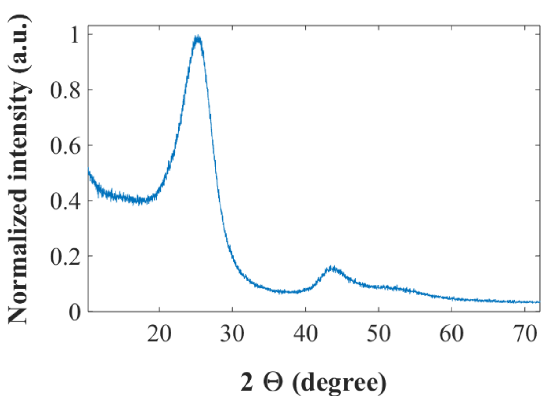
Figure 2.
(a) AFM height image of CNF; SEM images of CF/CNF films from (b) smooth side; and (c) rough side.
Figure 2.
(a) AFM height image of CNF; SEM images of CF/CNF films from (b) smooth side; and (c) rough side.

Figure 3.
SEM images of CF/SPC/CNF films at (a) smooth surface side; and (b) cross-section.

Figure 4.
SEM images of the LFP-CF electrodes at different magnifications: (a,b) LFP layer surface morphology; (c,d) CF layer morphology; and (e) cross-sectional SEM image.
Figure 4.
SEM images of the LFP-CF electrodes at different magnifications: (a,b) LFP layer surface morphology; (c,d) CF layer morphology; and (e) cross-sectional SEM image.

Figure 5.
Electrochemical performance of the flexible CF negative electrodes: (a) the fourth charge/discharge voltage profiles cycled at 0.1 C; (b) specific capacity cycled at 0.1 C; (c) coulombic efficiency cycled at 0.1 C; (d) rate capabilities of the CF/SPC/CNF electrode; and (e) voltage profiles at 0.1 C before and after 4000 times of repeated bending.

Figure 6.
Electrochemical properties of electrodes: (a) charge/discharge voltage profiles of the LFP-CF, LFP-Al and Quallion electrodes cycled at 0.1 C and 1 C; (b) EIS of the LFP-CF, LFP-Al and Quallion electrodes; (c) rate capabilities of the LFP-CF and Quallion electrodes; and (d) voltage profiles at 0.1 C before and after 4000 times of repeated bending.
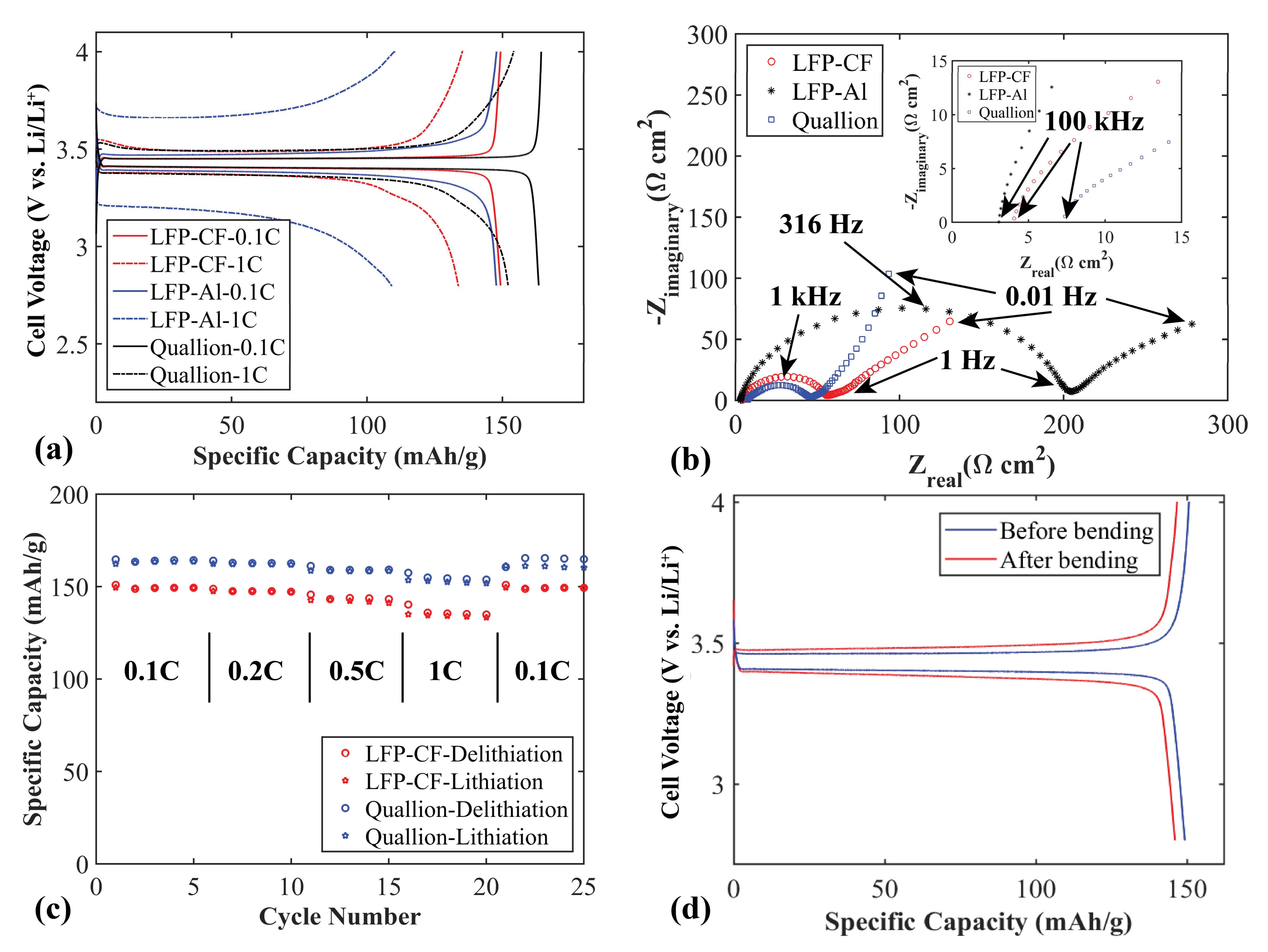
Figure 7.
(a) Active material weight percentage of electrodes and current collector. Grey bars: Commercial Quallion LFP and MCMB electrodes. Blue bars: Flexible LFP-CF and CF/SPC/CNF electrode. Electrochemical performance of the LFP-CF versus CF/SPC/CNF electrodes cycled at 0.1 C: (b) voltage profiles; (c) specific capacity; and (d) coulombic efficiency.

Table 1.
BET surface area of IMS65 CF, as well as the XRD-derived data before and after being chopped by a Wiley mill.
Table 1.
BET surface area of IMS65 CF, as well as the XRD-derived data before and after being chopped by a Wiley mill.
| BET Surface Area before Chopping (m2 g−1) | BET Surface Area after Chopping (m2 g−1) | d002 (Å) | Lc (Å) |
|---|---|---|---|
| 0.42 | 0.65 | 3.50 | 24.3 |
Table 2.
Mechanical properties and conductivity of flexible electrodes.
| Electrode | Young’s Modulus (MPa) | Ultimate Strength (MPa) | Strain at Break (%) | Conductivity (S m−1) |
|---|---|---|---|---|
| LFP-CF | 201 ± 12.7 | 1.97 ± 0.02 | 2.06 ± 0.29 | 95 |
| CF/SPC/CNF | 225 ± 10.7 | 1.91 ± 0.04 | 1.52 ± 0.12 | 143 |
Table 3.
Compositions of the films.
| Function | Layer | LFP (wt%) | CF (wt%) | SPC (wt%) | CNF (wt%) |
|---|---|---|---|---|---|
| Negative electrode | CF/CNF | - | 96 | - | 4 |
| Negative electrode | CF/SPC/CNF | - | 94 | 2 | 4 |
| Positive electrode | LFP/SPC/CNF | 85 | - | 11 | 4 |
| Current collector for positive electrode | CF/CNF | - | 96 | - | 4 |
© 2018 by the authors. Licensee MDPI, Basel, Switzerland. This article is an open access article distributed under the terms and conditions of the Creative Commons Attribution (CC BY) license (http://creativecommons.org/licenses/by/4.0/).
Share and Cite
MDPI and ACS Style
Lu, H.; Hagberg, J.; Lindbergh, G.; Cornell, A. Flexible and Lightweight Lithium-Ion Batteries Based on Cellulose Nanofibrils and Carbon Fibers. Batteries 2018, 4, 17. https://doi.org/10.3390/batteries4020017
AMA Style
Lu H, Hagberg J, Lindbergh G, Cornell A. Flexible and Lightweight Lithium-Ion Batteries Based on Cellulose Nanofibrils and Carbon Fibers. Batteries. 2018; 4(2):17. https://doi.org/10.3390/batteries4020017
Chicago/Turabian StyleLu, Huiran, Johan Hagberg, Göran Lindbergh, and Ann Cornell. 2018. "Flexible and Lightweight Lithium-Ion Batteries Based on Cellulose Nanofibrils and Carbon Fibers" Batteries 4, no. 2: 17. https://doi.org/10.3390/batteries4020017
Note that from the first issue of 2016, this journal uses article numbers instead of page numbers. See further details here.