1. Introduction
Advanced energy storage devices are desired to support next-generation consumer electronics and defense technologies, facilitate widespread electric vehicle adoption, and increase the penetration of renewably-generated electricity into the grid. Worldwide, research in battery materials and technology seeks to address these needs. Post-lithium ion batteries, including those based on lithium metal and other more abundant materials, are under active investigation. Next-generation battery electrolytes that allow for improved safety, maintained or longer device lifetimes, and that support post-lithium ion platforms are highly desired [
1,
2,
3,
4,
5,
6].
The most common Li-ion battery electrolytes that are used today are based on organic aprotic solvents, such as organic carbonates, and used in conjunction with a microporous polymer separator or imbibed in a polymer gel. These electrolytes exhibit high Li-ion conductivity and support an adequate solid-electrolyte-interface (SEI) formation, but they present many practical disadvantages, such as being volatile and flammable [
1,
5,
7,
8]. One class of electrolytes that are seen as a possible alternative are polymer electrolytes (PE). PEs offer many advantages, including improved thermal and electrochemical stability [
2,
9,
10]. Inorganic solid electrolytes typically have even better thermal stability, but they do not offer the same flexibility as PEs, which may inhibit their use in large-format devices [
5,
11].
A specific class of PEs of recent increased research interest is the single-ion conducting polymer electrolyte (SIPE) [
12]. The typical molecular structure of the SIPE for a lithium-ion battery is a lithiated ionomer with poly(ethylene oxide) (PEO) functionality and tethered anions [
13,
14,
15,
16,
17,
18,
19,
20,
21]. SIPEs can have very high oxidative stabilities and support higher charge/discharge rates than polymer electrolytes of similar conductivities and non-unity transference numbers [
16,
22]. The free anion in a traditional polymer electrolyte with a mobile salt is usually the limiting factor for electrochemical stability with the lowest oxidative stability in the electrolyte. In the SIPE, the anion is fixed to the polymer backbone and does not migrate to the anode where it would otherwise degrade.
The ionic conductivity of SIPEs is heavily influenced by the chemical nature of their anion. Anions with delocalized electron densities have been shown to enable high ionic conductivities, because the delocalized charge promotes dissociation of the ion pair and increases free cation concentration in the solvating polymer (such as the PEO chain) [
13,
18,
23,
24,
25,
26]. One such highly delocalized tethered anion is (4-styrenesulfonyl)(trifluoromethanesulfonyl)imide (STFSI). An even more delocalized tethered anion, 4-styrenesulfonyl)(trifluoromethyl(S-trifluoromethylsulfonylimino)sulfonyl)imide] (SsTFSI), has been shown to enable record ionic conductivity of a dry SIPE (1.35 × 10
−4 S/cm), however, its synthesis is complex [
13].
Furthermore, the macromolecular architecture also has a large impact on the performance of a SIPE. Longer amorphous chain segments allow fast segmental dynamics and, therefore, faster cation mobility; however, if the PEO segments are too long, the chains will crystallize resulting in drastically reduced cation mobility [
15,
18]. Electrolytes incorporating polymerized poly(ethylene glycol) methyl ether acrylate (PEGMA) have been shown to support high ionic conductivities over a wide temperature range. One such system is the random PEGMA-STFSI copolymer; unfortunately, these polymers are sticky gels and not convenient for battery fabrication [
17]. Previous work has been done with poly(ethylene glycol) diacrylate (PEGDA) to create crosslinked, polymer electrolyte films. An important potential advantage to these crosslinked polymer electrolytes is their ability to be blade-coated directly on electrode sheets. However, PEGDA is available commercially at low cost only for short chain lengths (
Mn~700 g/mol), and crosslinked electrolytes based on this short PEGDA and without liquid plasticizer exhibit quite low ionic conductivities. Potential solutions to this challenge include the use of longer chain PEGDA and the copolymerization of PEGDA and PEGMA [
27,
28,
29,
30,
31].
The most researched SIPE systems to date have been lithium-ion based SIPEs. Next-generation batteries based on other metals, such as Na, Mg, and Al, however, are under increasing investigation due to the increased widespread abundance of these elements. Lithium reserves are located in sporadic locations around the globe [
32,
33,
34,
35]. In contrast, Mg, Na, and K can be harvested commercially from ocean water [
32,
33,
34,
36]. The commercial availability of Mg, combined with its high energy capacity, makes Mg a great candidate for an alternative platform to Li for high energy density batteries [
36,
37,
38]. Other metals, including Na, have lower specific energy capacity, but are under active investigation for grid-level energy storage platforms [
39,
40,
41,
42,
43,
44,
45,
46,
47,
48].
Herein, we report on the ion transport properties of solvent-free, crosslinked SIPEs for post-lithium ion batteries. The use of longer chain PEGDA and the copolymerization of PEGDA and PEGMA are investigated in tandem with tethered anion chemistry and counter-cation type. The specific effects of segmental mobility and ion pairing on the conductivity are quantified via differential scanning calorimetry, Raman spectroscopy, and density functional theory (DFT) binding energy calculations.
2. Results and Discussion
Crosslinked electrolytes were prepared as described in the methods by the polymerization of PEGDA of varying molecular weights (
Mn = 700, 1000, 1600, 2150, and 4700 g/mol), PEGMA (
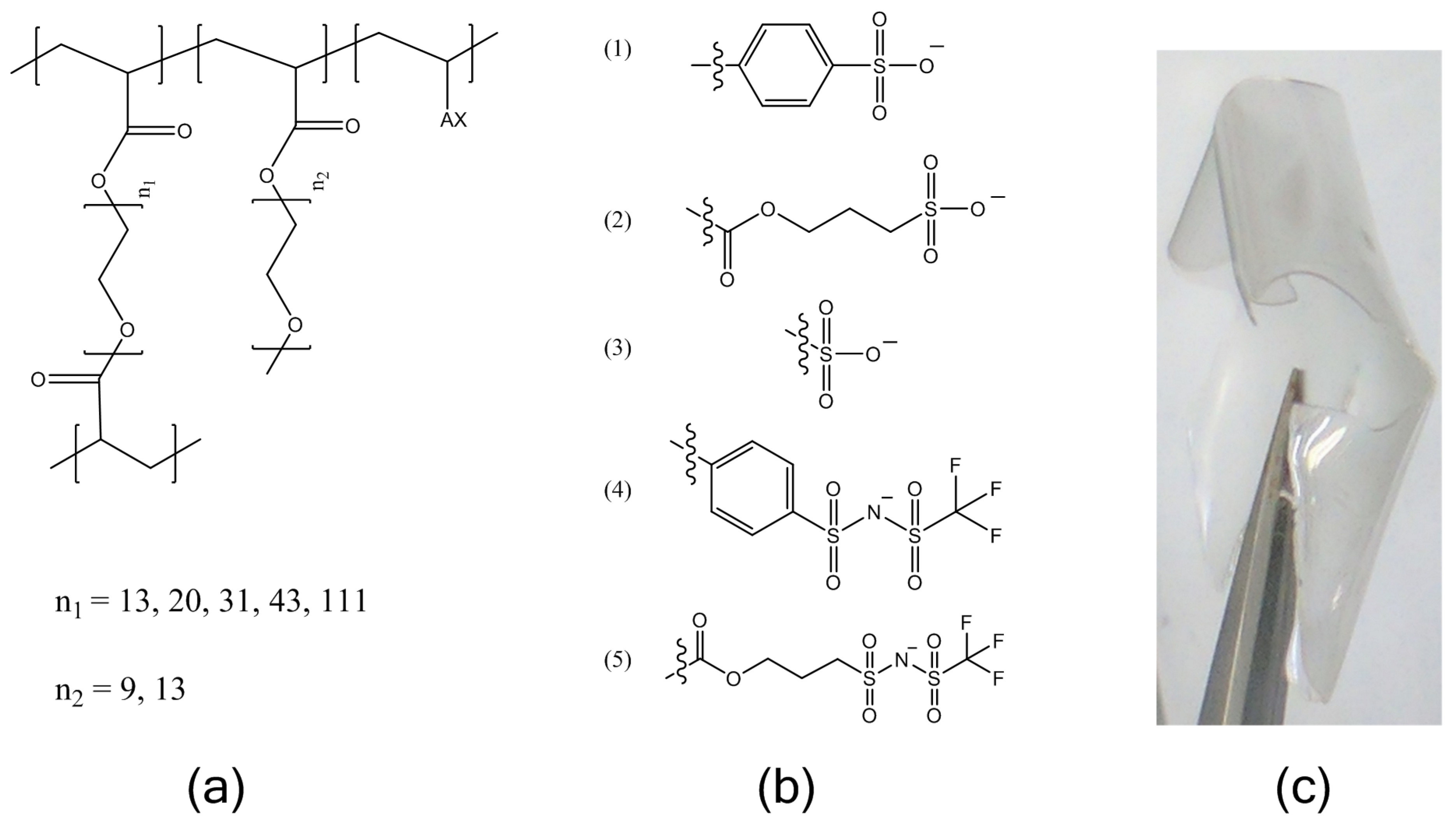
Mn = 480 g/mol and 750 g/mol), and an ionic monomer, followed by ion-exchange and drying. The molecular structures of the electrolytes are shown in
Figure 1. The ion content was held constant at a ratio of 1:30 moles charge:moles ethylene oxide (EO) for all cases described here. This ion content was chosen as we have found several poly(ethylene) glycol-based ionomers to have an optimum conductivity in an intermediate temperature range at this ion content. These include PEG
31DA-x-STFSILi and PEG
31DA-x-SSLi crosslinked ionomers as further studied here for temperatures of 40–90 °C, as well as the bottlebrush copolymer PEG
9MA-ran-STFSILi.
Lithiated single-ion conducting electrolytes were prepared with five different common tethered anions: styrene sulfonate (SS), vinyl sulfonate (VS), acrylate-propylsulfonate (APS), (4-styrenesulfonyl)(trifluoromethanesulfonyl)imide (STFSI), and acrylate-propyl(trifluoromethanesulfonyl)imide (APTFSI). The TFSI-derivatives have been shown to be more dissociable, resulting in higher ionic conductivities than the sulfonates, but the chemical structure of the polymerizable group alters the rigidity of the ionomer which also affects ionic conductivity. This experiment was undertaken so that the relative effects of ion pair dissociation and segmental mobility on the ion transport could be compared over the temperature range of −20 to 100 °C.
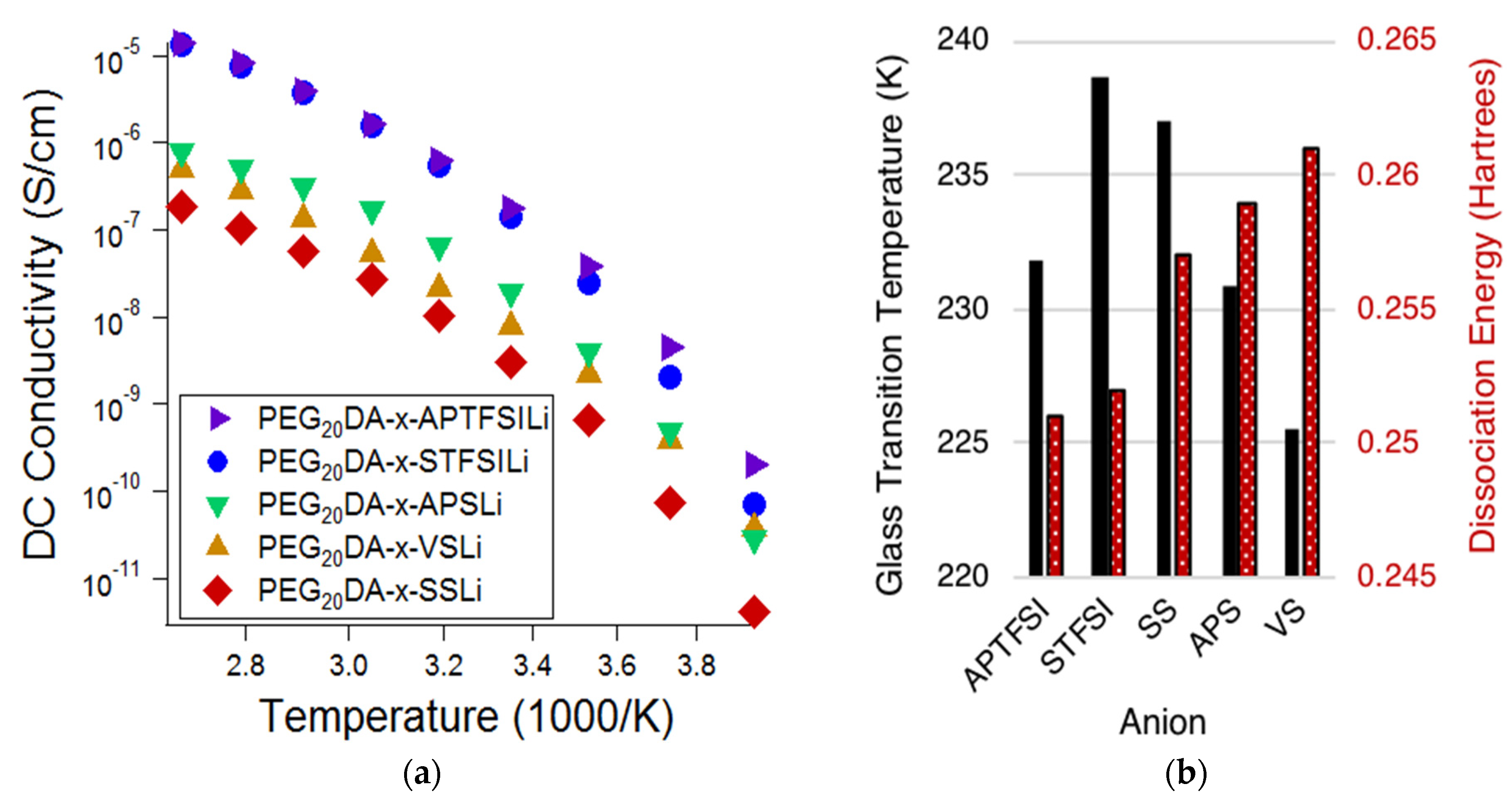
Figure 2a displays the ionic conductivity of the electrolytes based on the varying bound anions, while
Figure 2b displays the measured glass transition temperatures (
Tgs) of the electrolytes and the DFT predicted dissociation energies of the bound anion-Li ion pairs. Lower
Tgs are correlated with higher chain segmental mobilities, and lower dissociation energies are correlated with higher mobile cation concentrations. Comparison of
Figure 2a,b suggests that the degree of tethered anion dissociability most influenced the conductivity at high temperatures, whereas segmental mobility has an increased influence at low temperatures. Notice that at high temperatures, approaching 100 °C, the electrolytes containing TFSI-based anions exhibit ionic conductivities of over one order of magnitude greater than that of the sulfonate-based electrolytes; this difference is much diminished at low temperatures. This indicates that the ion pair dissociation and ion mobility have different activation energies [
19]. This effect is also made apparent when comparing styrenic and non-styrenic monomers. The influence of higher glass transition temperatures and, therefore, reduced segmental mobility for the styrene-based ionic monomers results in a more appreciable decrease in conductivity (𝜎) at lower temperatures. Specifically,
Tg,APTFSI <
Tg,STFSI and
Tg,VS <
Tg,APS <
Tg,SS; at −20 °C, 𝜎
APTFSI > 𝜎
STFSI and 𝜎
VS > 𝜎
APS > 𝜎
SS. This same trend does not hold at higher temperatures.
Of the investigated tethered anion types, electrolytes containing APTFSI exhibited the highest ionic conductivity over the measured temperature range with SFTSI electrolytes exhibiting just slightly lower conductivities. The remaining investigations reported here employed electrolytes based on STFSI, as despite the slightly reduced conductivities, we found that this monomer was easier to prepare with high purity.
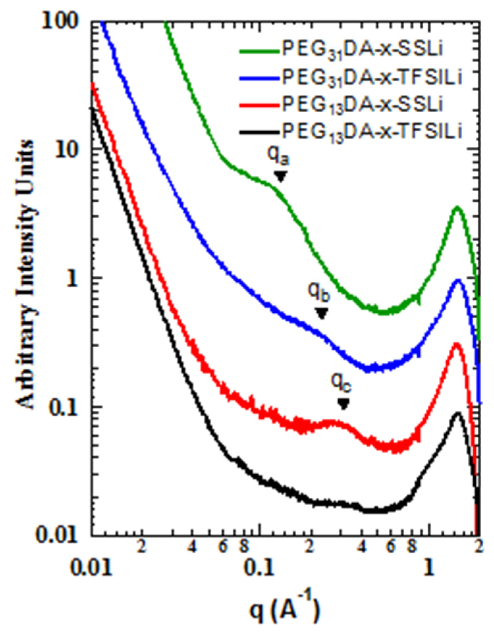
We also found that the differences in binding energies between the sulfonate and modified anions resulted in different mesoscale structures, as observed with small angle and wide angle X-ray scattering (SAXS-WAXS,
Figure 3). Markedly less structure was observed in the intermediate angle region, corresponding to nanometer length scales, for the crosslinked ionomers containing STFSI than for those containing SS. The correlation at point
qa, corresponding to a characteristic distance of about 5 nm, is clearly present in PEG
31DA-x-SSLi, but absent for PEG
31DA-x-STFSILi, which instead displays a minor shoulder at point
qb, a real-space distance of about 2.5 nm. Likewise, PEG
13DA-x-SSLi clearly displays a correlation length at point
qc, a characteristic distance of about 2 nm, which is again much less prominent for PEG
13DA-x-STFSILi. For these materials we hypothesize that evolution of a correlation length is indicative of the formation of ionic aggregates, a process which is partly governed by the degree of ion pair dissociation. With a low degree of dissociation, as is observed in the case of the SS anion, ionic charges are screened due to anion-cation pairing. This allows for the micro-phase separation of the polymers into PEGDA-rich and ionic unit-rich domains, a process which is subject solely to the physical constraints of the network crosslinking. However, as the dissociation degree increases, a greater number of unpaired anions exist in the crosslinked network. The tethered negative charges of the unpaired anions mitigate aggregation via electrostatic repulsion, resulting in a more uniform distribution of scatterers.
As the network crosslinker chain length increases, the ability of the polymer to accommodate greater aggregation increases, which results in the longer characteristic distances between ionic aggregates in the case of PEG31DA-x-SSLi relative to PEG13DA-x-SSLi. In addition, longer crosslinkers facilitate aggregation in the case of the PEG31DA-x-STFSILi, as the enhanced conformational freedom of the PEG31DA allows for the exclusion of unpaired anions while facilitating some degree of micro-phase separation of paired ionic groups.
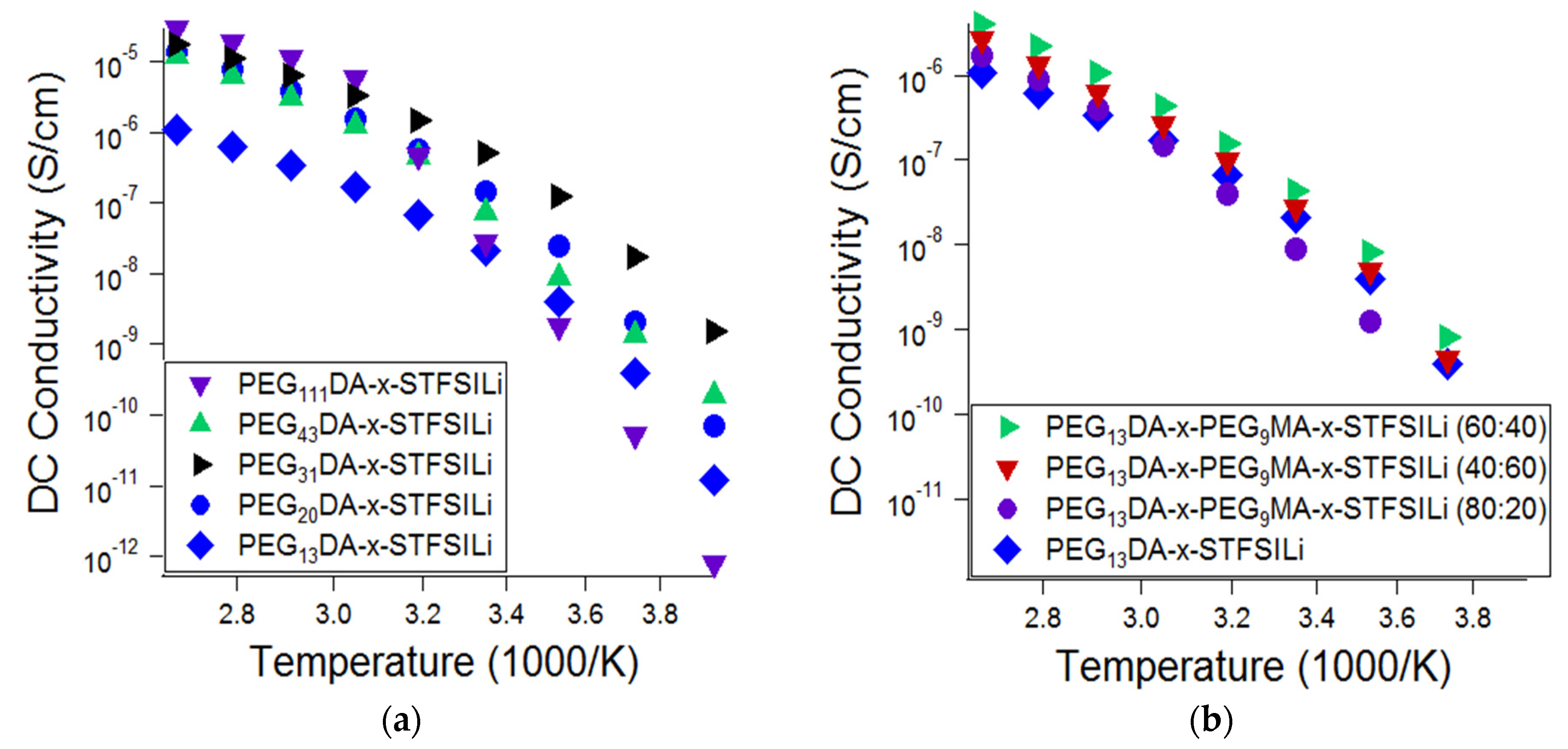
The influence of the network morphology of the lithiated crosslinked ionomers, namely the crosslinker length and presence branching, on the ionic conductivity was also investigated (
Figure 4). Glass transition and melting transition temperatures, as well as ionic conductivity at 55 °C, as a function of crosslinked ionomer composition, is summarized in
Table A1 in
Appendix A. Ionic conductivity was found to be a strong function of PEGDA crosslinker length at ambient temperature, with PEG
31DA resulting in the highest ionic conductivity at temperatures up to 40 °C. For temperatures in the range of 55 °C to 100 °C, the conductivity of the electrolytes prepared with crosslinkers in the range of PEG
20DA to PEG
111DA was similar. These results are attributed to the competing effects of segmental mobility, ion pairing, and crystallization. Glass transition temperatures decreased and, therefore, segmental mobility increased, with increasing crosslinker length. Crosslinkers of PEG
43DA and longer were found to create networks that crystallized, resulting in a drop off in ionic conductivity at temperatures below the amorphous-crystalline transition. Crosslinkers of PEG
31DA and PEG
20DA, while semi-crystalline in the monomer form, produced crosslinked networks that remain amorphous at all temperatures. Finally, we suspect that there is an effect of tethered anion proximity that results in increased ion pairing for the long crosslinkers. On average, there are more adjacent tethered anions with increased crosslinker length for materials with the same overall ion content. Anions adjacent along the chain are more likely to have polarizability volume overlap, which results in a lower degree of cation dissociation and therefore a lower effective mobile ion number [
49,
50]. These combined effects explain the non-monotonic relationship of ionic conductivity and network crosslinker length at various temperatures.
The addition of PEGMA combs was found to only modestly improve the ionic conductivity of the electrolytes, if at all. Representative data is shown in
Figure 4b, which shows the effect of varying the ratio of PEG
9MA to PEG
13DA in the range of 0:1 to 4:1, where ionic conductivity is improved only in limited cases. We also investigated the addition of PEG
9MA combs to networks based on PEG
20DA, as well as the addition of PEG
14MA to networks based on PEG
31DA, and found similar results. Thus, we conclude that greater enhancements in conductivity due to chain branching are likely only when the networks approaches a loosely crosslinked bottlebrush, wherein there are nearly all PEGMA combs and a limited number of PEGDA crosslinkers. With the network fabrication methods utilized here and described in the experiment, we were unable to realize a soft solid of this morphology.
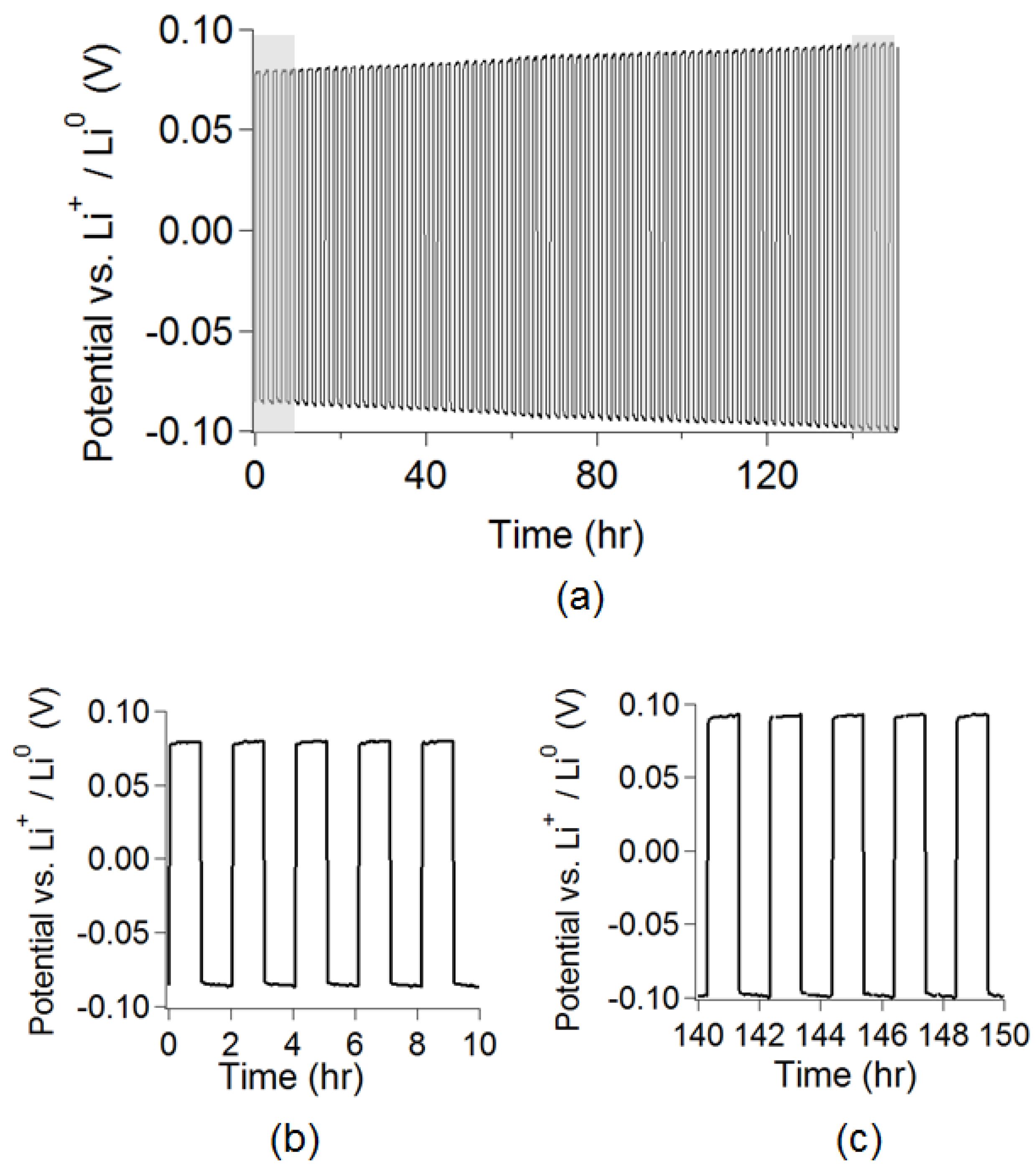
The lithiated crosslinked electrolyte PEG
31DA-x-PEG
14MA-x-STFSILi was employed in a symmetric lithium metal coin cell and galvanostatically cycled to confirm its ability to reversibly strip and plate lithium metal. This electrolyte does effectively cycle lithium metal, as shown in
Figure 5, with a small, but observable, increase in resistance over 150 h.
With an eye toward post-lithium ion battery chemistries based on more abundant elements, crosslinked electrolytes were exchanged to other metal cations using aqueous ion-exchange solutions of other metal chloride salts. The metal cation–STFSI binding energies were predicted using DFT calculations and compared to the percentage of unpaired anions as measured using Raman spectroscopy and the ionic conductivity. As shown in
Figure 6, for electrolytes based on Li, Na, K, Al, Mg, and Ca, the variation in the ionic conductivity due to cation type is about two orders of magnitude at 100 °C and over three orders of magnitude at −20 °C. Across these temperatures, lithiated electrolytes were the most conductive, while calcinated electrolytes were the least conductive. Surprising, aluminated electrolytes were found to have lower ionic conductivity than those with alkali (+1) cations, but higher ionic conductivity than the alkaline earth (+2) cations. Elemental analysis revealed that these electrolytes contain 1.5 times the aluminum predicted based upon Al(STFSI)
3 complexation, thus, there are chloride anions remaining. The resultant aluminum chloride complexes (could include AlCl
2+, AlCl
4−, etc.) have faster transport rates in the polyether ionomer than the bare divalent cations Mg
2+ and Ca
2+. The low ionic conductivity of the hard divalent cations Mg
2+ and Ca
2+ in poly(ethylene oxide) has been documented in other works and is attributed to the divalent cation acting as a crosslinking point, strongly linking adjacent chains [
51,
52]. The conductivity of the Na and K containing electrolytes is close to that of the lithiated electrolyte at high temperatures, thus, we suggest that these electrolytes be further considered for use in elevated temperature Na and K battery systems.
Raman spectroscopy was used to further characterize the electrolytes to evaluate the relative influences of free cation number and cation mobility on ionic conductivity. First, theoretical Raman spectra were generated using DFT in order to support the experimental Raman peak identification. A directory summarizing the DFT inputs/outputs is available as
Supplemental Materials. A DFT prediction using the PBE method with a 6311++G(d,p) basis for the LiSTFSI molecule showed that the vibrational mode that is associated with the S-N-S bonds expanding and contracting symmetrically was significantly affected by coordination with a cation. The shift from the free to the paired state was ~18 wavenumbers for coordination with Li
+; specifically, the free peak was predicted at 691 cm
−1 while the peak was predicted at 673 cm
−1 for the lithiated anion. Furthermore, DFT predictions showed no significant Raman modes within 80 cm
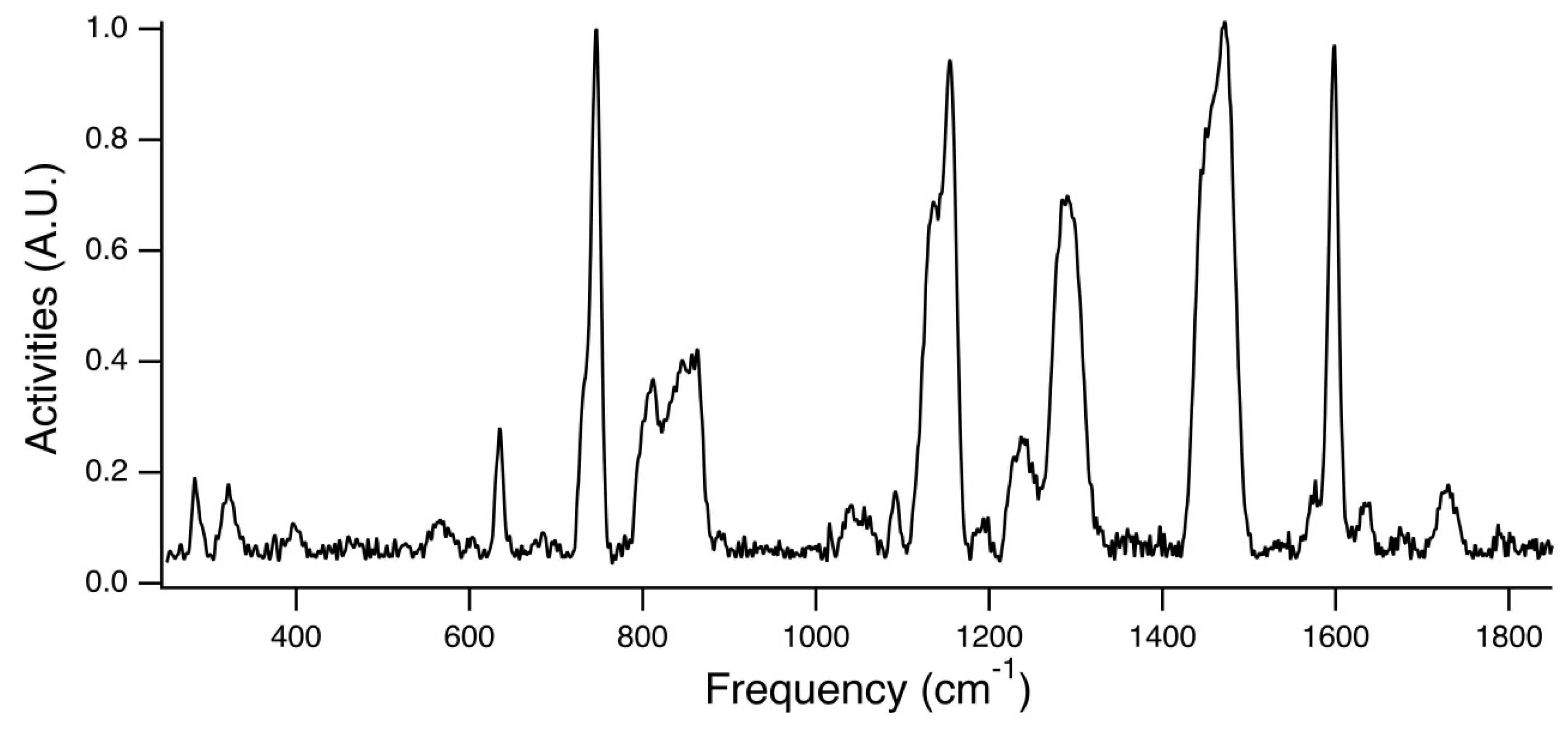
−1 of this characteristic STFSI peak, indicating that this peak would be relatively undisturbed by the surrounding signal from the STFSILi molecule. Shown in
Figure 7 is the experimental Raman spectra for PEG
31DA-x-STFSILi, and
Figure 8 displays an enlarged view of the region of interest. The peak at ~732 cm
−1 is attributed to the unpaired STFSI- population, whereas the peak at ~746 cm
−1 is attributed to the STFSILi ion pair. Note that these modes occur at wavenumbers similar to that found for the common TFSI- anion, CF
3SO
2NSO
2CF
3− [
26,
53,
54]. In no case could a peak be identified at a sufficient signal-to-noise ratio that corresponded to the cationic triplet, STFSILi
2+. Notably, the Raman spectra of the electrolytes with varying metal cations appeared quite similar in this region in that two distinct peaks were apparent that we attribute to free STFSI and paired STFSI. For divalent metal cations, non-negligible populations of the neutral triplet are anticipated, i.e., STFSI
2Mg. The peak associated with this neutral triplet is predicted to occur close to that STFSIMg
+, but could not be unambiguously identified at the level of noise present. Thus, in the following estimations of free and paired STFSI populations for the Mg and Ca-exchanged electrolytes, both the charged and neutral triplets are accounted for as part of the paired STFSI population. Unfortunately, the Al-exchanged electrolyte PEG
31DA-x-STFSIAl was opaque and, thus, the collected signal intensity was not high enough to produce a meaningful Raman spectrum for this composition.
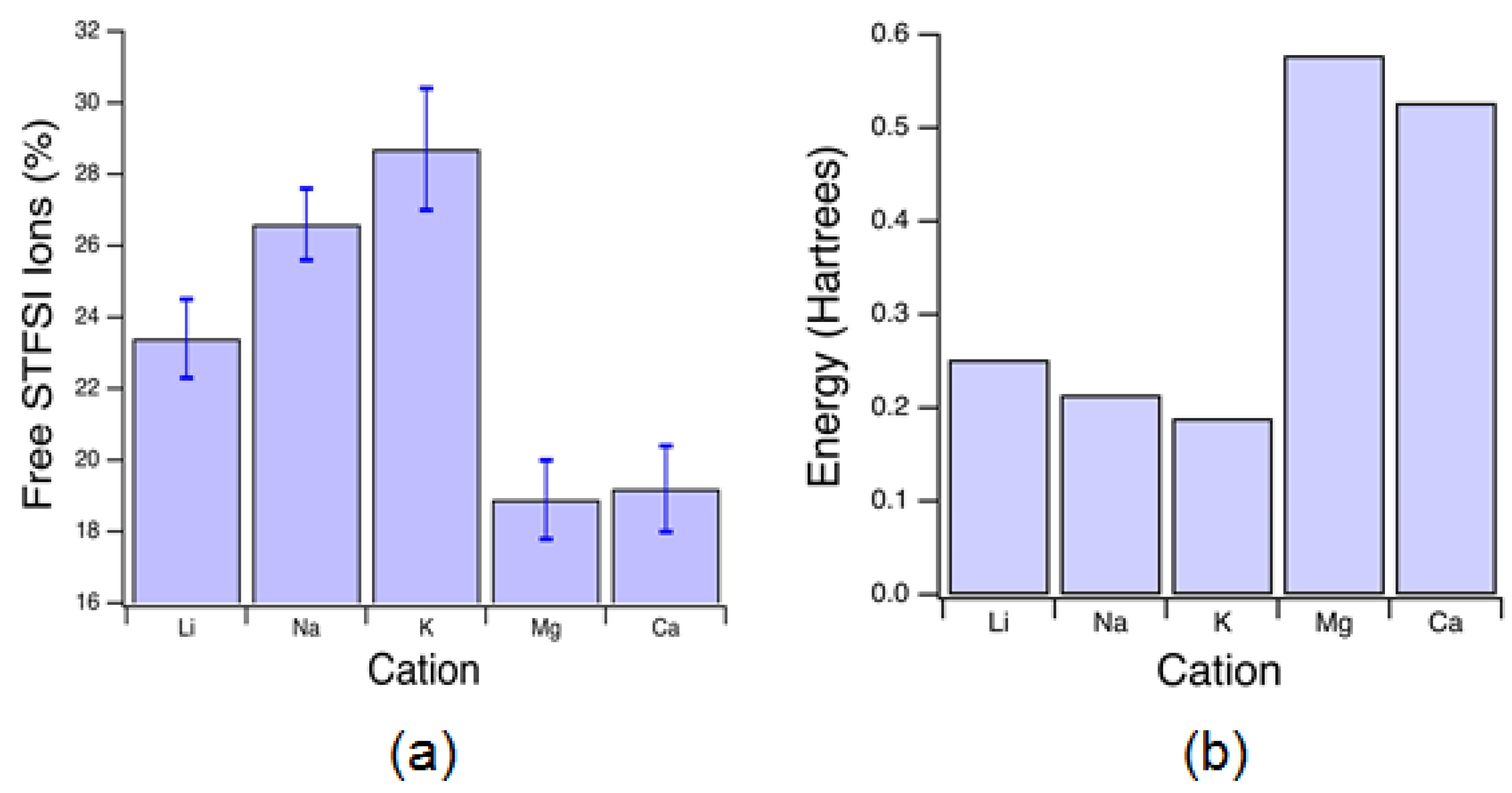
Raman spectra were fit to provide estimations of the percentage of unpaired anions, see
Figure 9a. For monovalent cations, the percentage of unpaired anions is exactly equivalent to the percentage of unpaired cations. Increasing ion size at equivalent valency, corresponding to decreased charge density, resulted in increased unpaired anion fractions. The highest unpaired fraction measured was 29 ± 2% for K-exchanged electrolytes, compared with the lowest unpaired fraction of about 19% for Mg-exchanged electrolytes, a relative decrease of less than 35%. This was found surprising given the three-fold difference in STFSI-cation binding energies as predicted from DFT, shown in
Figure 9b. However, for divalent cations, this binding energy is that predicted for STFSI
- and X
2+; the binding energy for STFSI
− and STFSIX
+ is expected to be considerably lower. Hence, for multivalent cations, the percentage of unpaired anions is not equivalent to the percentage of unpaired anions. Thus, with this analysis we are unable to unambiguously attribute the low divalent cation conductivity observed in
Figure 6 to low numbers of mobile cations or low conducting cation mobility in the matrix.
The number of free alkali cations, as determined from the total cation mass fraction and material density, may be used in concert with the conductivity equation and the Nernst-Einstein equation to provide an estimate of the conducting cation mobility for the case where the conducting species is the free, monatomic cation. The ionic conductivity,
, is the product of the conducting ion number (
), ion charge (
), and ion mobility (
):
The ion mobility is related to the ion diffusivity,
, as follows:
where
is the Boltzmann constant and
is the temperature. Using the unpaired cation fraction of −23% for Li
+ as determined from Raman spectroscopy and a measured density of 1.28 g/mL, we estimate the Li
+ diffusivity in PEG
31DA-x-STFSILi as 6 × 10
−24 cm
2/s at 20 °C. Na
+ and K
+ diffusivities at 20 °C are estimated as 5 × 10
−25 and 3 × 10
−25 cm
2/s, respectively, for PEG
31DA-x-STFSINa and PEG
31DA-x-STFSIK.
The Li
+ diffusivity value estimated here should in the future be compared to the
7Li self-diffusion coefficient as measured via pulse-field gradient nuclear magnetic resonance spectroscopy (PFG-NMR) [
55]. While several other works have used Raman spectroscopy to estimate the degree of TFSI anion coordination in electrolytes such as ionic liquids, we believe that this is the first effort to apply this approach to single-ion conducting polymers with tethered STFSI anions. A prior work used FTIR to estimate the degree of tethered sulfonate coordination in a different single-ion conducting polymer [
50]. Few simple methods exist for assessing the populations of free and coordinated cations, and diffusion coefficient measurements via PFG-NMR require more expensive instrumentation and are limited to certain nuclei such as
7Li and
1H.
4. Materials and Methods
4.1. Materials
The majority of chemicals were obtained from Sigma-Aldrich (St. Louis, MO, USA), including: poly(ethylene glycol) (PEG) of average molecular weights 1500, 2050, and 4600 g/mol, poly(ethylene glycol) methyl ether acrylate of average molecular weights 480 and 750 g/mol, poly(ethylene glycol) diacrylate of average molecular weight 700 g/mol, triethylamine, acryloyl chloride, thionyl chloride, oxalyl chloride, dichloromethane (DCM), tetrahydrofuran (THF), diethyl ether, anhydrous acetonitrile, dimethylformamide (DMF), methanol, pentane, 4-(dimethylamino)pyridine, lithium chloride, magnesium chloride, sodium chloride, aluminum chloride hexahydrate, calcium chloride, potassium carbonate, sodium bicarbonate, lithium hydride, hydrochloric acid, and 2-hydroxy-4′-(2-hydroxyethoxy)-2-methylpropiophenone (photoinitiator). Poly(ethylene glycol) diacrylate of average molecular weight 1000 g/mol was obtained from Polysciences (Warrington, PA, USA). Trifluoromethanesulfonamide was obtained from TCI America (Portland, OR, USA). All reagents were used as received.
4.2. Synthesis of Potassium 4-Styrenesulfonyl(trifluoromethylsulfonyl)imide (KSTFSI)
KSTFSI was synthesized via a previously reported procedure [
18]. Oxalyl chloride (20 g, 157 mmol) and 0.55 mL DMF were added to 250 mL anhydrous acetonitrile and stirred for five hours under a nitrogen atmosphere to form the yellow Vilsmeier-Haack complex. To this solution, 25 g (121 mmol) of 4-styrenesulfonate sodium salt were added and the mixture was stirred for one day. The resultant NaCl salt was removed from the 4-styrene sulfonyl chloride solution via filtration. Separately, 51 mL of triethylamine, 18.04 g trifluoromethylsulfonamide (121 mmol), and 9% by weight 4-(dimethylamino)pyridine were added to 188 mL of anhydrous acetonitrile and allowed to dissolve under nitrogen. This solution was added dropwise to the 4-styrene sulfonyl chloride solution at 0 °C, and then stirred for 16 h. The final solution was concentrated via rotary evaporation, and the resultant solids were dissolved in 50 mL of dichloromethane. The dichloromethane solution was washed with 3 × 90 mL of 4% NaHCO
3 followed by 2 × 125 mL of 1 M hydrochloric acid. The washed organic solution was concentrated, with the acid monomer residue neutralized by the addition of one molar excess of K
2CO
3 dissolved in deionized (DI) water. The KSTFSI monomer was obtained by subsequent recrystallizations from DI water until confirmed pure via
1H and
13C NMR.
4.3. Synthesis of Lithium 1-[3-(Acryloyloxy)propylsulfonyl]-1-(trifluoromethane-sulfonyl)imide (LiAPTFSI)
LiAPTFSI was synthesized via a previously reported procedure [
56]. Briefly, the purchased potassium 3-(acryloyloxy)propane-1-sulfonate was dried and then converted to 3-(chlorosulfonyl)propyl acrylate via reaction with excess thionyl chloride. Then, 3-(chlorosulfonyl)propyl acrylate was converted to triethyl ammonium 1-[3-(acryloyloxy)propylsulfonyl]-1-(trifluoromethane-sulfonyl)imide by reaction with trifluoromethanesulfonamide in the presence of trimethylamine. The monomer was then lithiated by reaction with lithium hydride (2.5 times excess) in THF. The product was recrystallized from dichloromethane, washed with pentane, and dried under high vacuum. The structure was confirmed via
1H and
13C NMR though the yield was low (21% for the final lithiation and purification steps).
4.4. Synthesis of Poly(ethylene glycol) Diacrylate (PEGDA)
PEGDA was synthesized in accordance with prior literature [
57]. PEGs (
Mn = 1500, 2050, and 4600 g/mol) were dissolved in DCM and reacted with triethylamine and 2.2 equivalents of acryloyl chloride in a dark environment at 0 °C (gradually increasing to room temperature) under a nitrogen atmosphere. The solution was concentrated via rotary evaporation to roughly 25% of the original volume, to which THF was added to precipitate triethylamine hydrochloride salts. The solution was then further concentrated to an oily residue, dissolved in 5 mL dichloromethane, and precipitated in chilled diethyl ether. The PEGDA monomer was collected via filtration and dried under vacuum for 24 h. Attachment of acrylate groups and purity was confirmed by
1H NMR.
4.5. Preparation of Crosslinked Electrolytes
PEGDA of the required molecular weight was dissolved in DMF. The ionic monomer was added in the ratio of 30 PEGDA ethylene oxide units to one ionic monomer, and photoinitiator was added at the molar ratio of 0.01 mol/mol monomer. The mixture was exposed to UV radiation (UVC 515 Ultraviolet Multilinker, Ultra-Lum, Inc., Carson, CA, USA) and heated to 80 °C for the polymerization reaction. The polymerized films were then washed and ion-exchanged to the form of interest. First, the films were transferred to methanol, then to a 0.4 M aqueous ion exchange solution for 96 h with solution changes every 24 h and, finally, a pure water bath. The films were dried in the open atmosphere for 24 h, and finally dried in a glovebox under vacuum at 80 °C for 16 h.
4.6. Ionic Conductivity
Film conductivity was measured using a Broadband Dielectric/Impedance Spectrometer model Alpha A (Novocontrol Technologies, Montabaur, Germany) with symmetric brass electrodes. Measurements were taken at 15 °C intervals from −20 °C to 100 °C. AC voltage was set to 0.1 V and the frequency was swept from 107 Hz to 0.1 Hz.
4.7. Thermal Properties
The glass transition temperature (Tg) and melting temperature (Tm) were measured using differential scanning calorimetry (Mettler Toledo, DSC 1, Columbus, OH, USA) at a heating rate of 10 °C min−1 under a nitrogen atmosphere, on the second heating leg of a heat-cool-heat cycle.
4.8. DFT Calculations
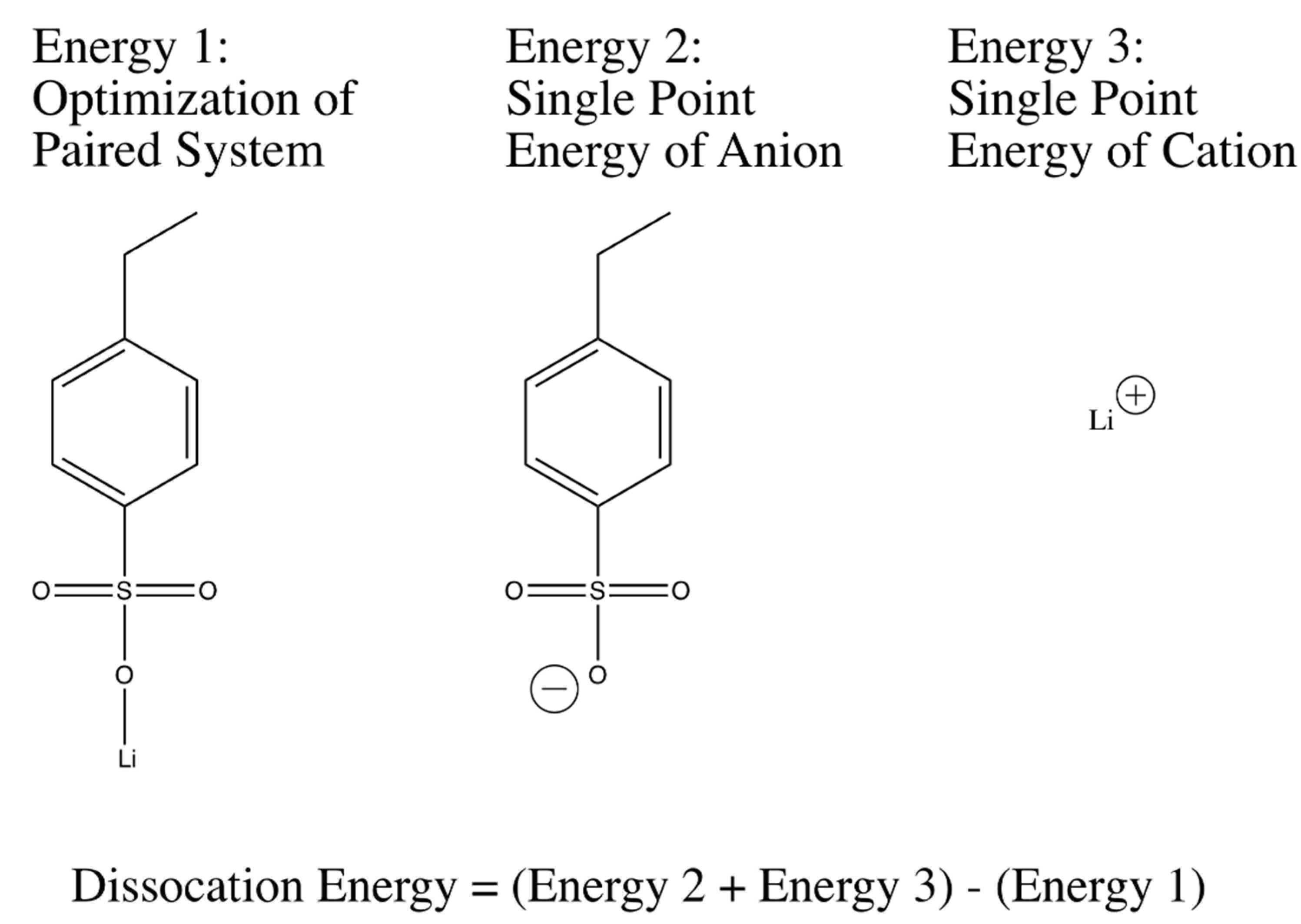
Geometric optimizations and single point energy calculations of anion-cation systems were used to calculate dissociation energies were performed in accordance with the widely-used three-parameter Becke model with the Lee-Yang-Par modification (B3LYP) [
58,
59]. The basis set that was used for all of the optimizations and single point energy calculations was 6-311++G(d,p), a large basis set containing diffusive functions that help deal with the distributed charge in the system, especially the anions in question. Dissociation energy correlations between different tethered anions in the system were determined starting with an optimization of the geometry of a single anion and a single monatomic cation. The final geometry for the molecule was then used to obtain a structure for the anion of the system. A single point energy calculation with the same method and basis was then performed on the anion. Additionally, a single point energy of the monatomic cation was also calculated. The three energies that had been calculated were then used to calculate a dissociation energy as shown in
Figure 2 and
Figure 9. Dissociation energies were also tested with a varying size of bases, and were shown to converge to the reported values with increasing basis size. Furthermore, cations were placed in many different positions for the start of optimization in order to ensure the finding of the global minimum in calculations. It should also be noted that in the salt systems studied in this paper originally contained a double bond that was used to polymerize the salt to the PEGDA system. This double bond was altered to a fully-hydrogenated single bond in the DFT calculations in order to simulate a structure more similar to the ones present in the studied polymers. Various starting geometries were tested in order to ensure the global minimum of geometric optimization was found.
The method illustrated in
Figure 10 was extended to many different anion-cation systems to obtain relative dissociation energy predictions. For the dissociation energy calculations of lithium 3-sulfopropyl acrylate (LiAPS) and lithium 4-propylacrylatesulfonyl(trifluoromethylsulfonyl)imide (LiAPTFSI), the oxygen atoms in the acrylate group were substituted with fully hydrogenated carbon atoms. The effect of the acryl oxygen atoms to the dissociation energy of LiSPA and LiSPTFSI in the real PEGDA-containing system is substantially diluted at the charge:EO ratio of 1:30, as used here.
Theoretical Raman spectroscopy was also calculated using the 6-311++G(d,p) basis set and the generalized gradient approximation (GGA) method proposed by Perdew, Burke, and Ernzhof [
60]. This GGA method will be referred to as “PBE” throughout the rest of the paper. This method was used because it is known to give similar results to B3LYP with a much smaller computational cost. The specific peak shifts that were studied in this paper corresponded to the difference in anion’s vibration when it was paired with a monatomic cation, as opposed to when it was in the unpaired, “free”, state. These shifts were determined by optimizing the tethered anion and calculating a Raman spectrum then optimizing the free anion and calculating Raman spectrum for comparison. Shifts of interest, which contained the same vibrational modes, were determined by using the Avogadro software to visualize the calculated vibrations [
61]. All calculations were performed using the Gaussian09 computational software [
62].
4.9. Raman Spectroscopy
Polymer films that were previously prepared in an argon box were then placed in a Teflon-sealed quartz cuvette inside the same glove box. The samples were flush to the quartz glass when they were taken out of the glove box. Raman Measurements were taken using a NRS-5000 Mirco-Raman Spectrometer (Jasco, Inc., Easton, MD, USA) with the 20× objective magnification. A 532 nm excitation laser was used as well as a resolution of 13.8 cm−1. It should be noted that peak shapes were not significantly changed at a large range of resolutions (0.7 to 13.8 cm−1), so the lowest resolution was used in order to increase the signal-to-noise ratio. The spectra were recorded every 1 cm−1.
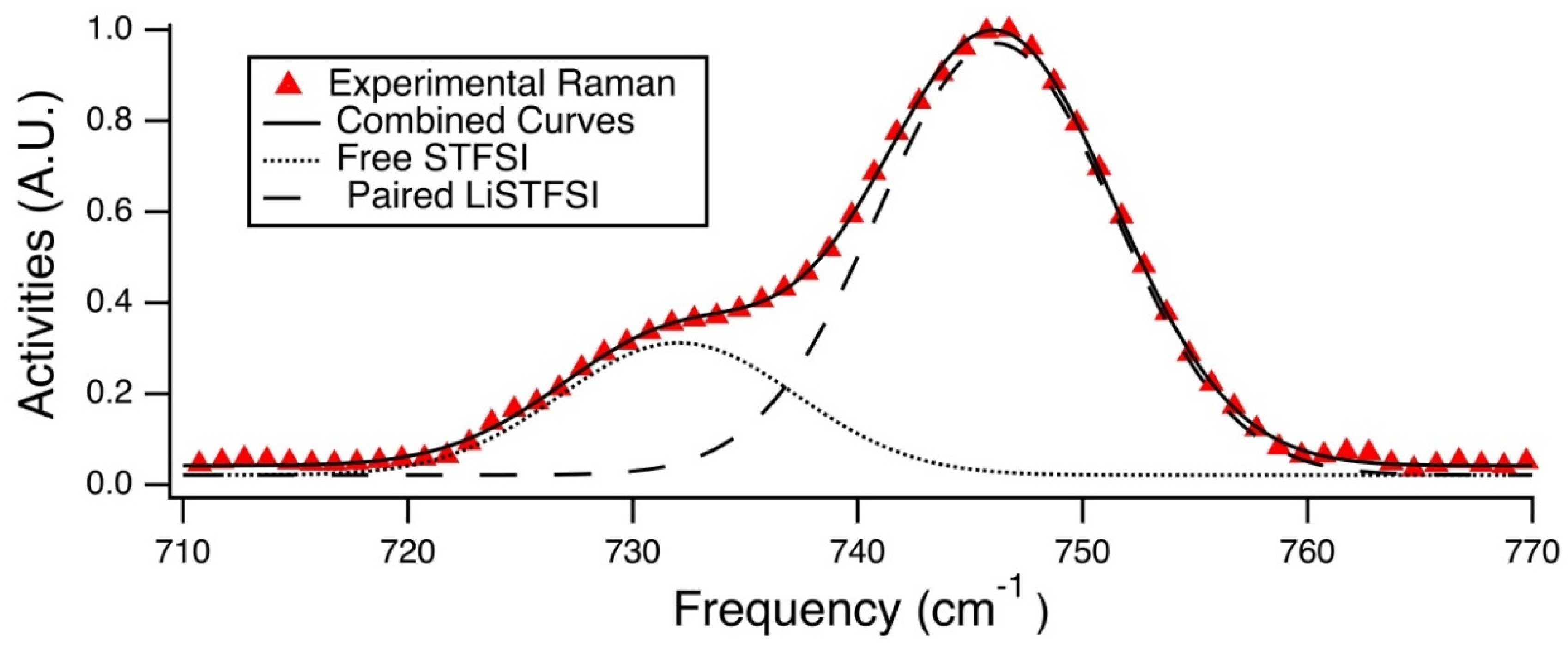
Population analysis was done via Gaussian curve fitting of these Raman spectra in the range of 710 cm
−1 to 770 cm
−1. The peak at ~746 cm
−1 corresponds to the paired STFSI anion, and the shoulder occurring at a lower wavenumber corresponds to the free STFSI anion. Using this knowledge, the Beer-Lambert law was applied to the area integrations for the two Gaussian curves that were fit to the these modes, shown in
Figure 8, in order to determine the fraction of free STFSI anions. It should be noted that this calculation of free ions did not take into account any cation-anion configurations other than a single anion bound to one monatomic cation. Other geometric possibilities that could be present and have similar Raman activities. These geometries for monovalent cations include the triplet (STFSILi
2+), the negatively-charged coordination of two anions and one cation ([STFSI]
2Li-). For the divalent cations ([STFSI]
2Mg) is also a possibility. With relatively low signal-to-noise ratios, our analysis is somewhat restricted in determining which of these states are actually present in the electrolytes.
The error analysis that was performed on the free ion percentage calculations, shown in
Figure 9, was done via Monte Carlo simulation. This was accomplished by taking a section of spectrum that was known to not have any signal and extracting an average random error to the known zero point. This random error was then introduced into the fitting Gaussian curves at random along the fitted curve. This new noisy curve was then fit using the same Gaussian curve fitting algorithm as the original data. The resulting two Gaussian curves were used to obtain a new population estimate. This population was stored, and the process was repeated 1000 times. A standard deviation was taken of all of the resulting population percentages, and a two standard deviation limit was placed on
Figure 9 to depict a 95% confidence interval.
4.10. Galvanostatic Cycling
Li/PEG31DA-x-PEG14MA-x-STFSILi/Li coin cells, size 2032, were assembled in an argon glovebox. After a 24 h rest at room temperature and one hour rest at 70 °C, the coin cell was galavanostatically cycled at a rate of 50 μA/cm2 for 2 h for each complete cycle at 70 °C using a BTS3000 battery tester (Neware, Shenzhen, China) with wiring into a gravity oven (VWR, Radnor, PA, USA).
4.11. Small Angle and Wide Angle X-Ray Scattering (SAXS-WAXS)
SAXS-WAXS measurements were obtained using the Advanced Photon Source (beamline 12-ID-B, operated by the Chemical and Materials Science Group) at Argonne National Lab, with an X-ray beam wavelength of 0.9322 Å (photon energy of 13.3 keV). The
q-range was calibrated using a silver behenate standard, and the sample to detector distance was maintained at 2013 mm for the SAXS detector and 430.15 mm for the WAXS detector. Samples were prepared by loading the polymer films into glass or quartz capillary tubes (Charles Supper Company, Natick, MA, USA) and which were then sealed with wax under an argon atmosphere. Two-dimensional (2D) spectra were obtained with an exposure time of one second, collected with a Pilatus 2M camera (Dectris, Baden-Dättwil, Switzerland) for SAXS and Pilatus 300 for WAXS, and converted to 1D spectra via azimuthal integration. Spectra were corrected for transmission and background, and analyzed using the Igor Pro-Irena SAS package to display an arbitrary intensity vs scattering vector
q, for:
where
is the X-ray wavelength and
is half of the scattering angle, 2
.
4.12. Elemental Analysis
Inductively coupled plasma optically emitting spectroscopy (ICP-OES) was completed using a PerkinElmer Optima 8000 to quantify the amount of metal in the polymer films. Samples were digested by refluxing for 16 h in concentrated nitric acid (70%), then diluted to 5% nitric acid using 18 MΩ water. Calibration standards were made from 1000 ppm standards in 2% nitric acid (TraceCERT from Sigma Aldrich).

 and
and 


