Mechanical Processing of GFRP Waste into Large-Sized Pieces for Use in Concrete

City College of New York, New York, NY 10031, USA
*
Author to whom correspondence should be addressed.
Recycling 2018, 3(1), 8; https://doi.org/10.3390/recycling3010008
Submission received: 23 December 2017
/
Revised: 9 February 2018
/
Accepted: 12 February 2018
/
Published: 15 February 2018
Abstract
:Recycling glass fiber reinforced polymer (GFRP) composite materials has been proven to be challenging due to their high mechanical performance and high resistance to harsh chemical and thermal conditions. This work discusses the efforts made in the past to mechanically process GFRP waste materials by cutting them into large-sized (cm scale) pieces, as opposed to pulverization, for use in concrete mixtures. These pieces can be classified into two main categories—coarse aggregate and discrete reinforcement, here referred to as “needles.” The results from all the studies show that using GFRP coarse aggregate leads to significant reductions in the compressive strength and tensile strength of concrete. However, GFRP needles lead to sizable increases in the energy absorption capacity of concrete. In addition, if the glass fibers are longitudinally aligned within the needles, these elements can substantially increase the tensile strength of concrete. Processing GFRP waste into needles requires less energy and time than that for producing GFRP coarse aggregate. Also, compared to pulverized GFRP waste, which consists of broken and separate particles of glass and resin that at best can be used as low-quality fillers, GFRP needles are high strength composite elements.
1. Introduction
For the last three decades, fiber-reinforced polymer (FRP) composite materials have been used extensively and increasingly in major industries. FRP typically consist of fibers encased in a matrix of resins with fiber concentrations typically in the range of 12–60% by volume [1]. It is estimated that in the United States, the annual demand for FRP materials, 95% of which made with glass fibers [2], has climbed to nearly two million metric tons in 2017 (over 20% increase since 2007) [3]. When these GFRP products reach the end of their service lives, the annual GFRP waste produced in the U.S. (including the production scrap, which is approximately 5% of produced GFRP) will be at least 2 million metric tons, with increasing values in the subsequent years.
GFRP materials have remarkable physical and mechanical properties; they can be over two times stronger than steel in tension at only a quarter of the weight [4]. Although these materials are extremely durable in corrosive environments at low temperatures (<80 °C) their life spans can be relatively short due to low design allowables and functional obsolescence. For example, wind turbine blades, with GFRP as the main material used in the structure and outer shell of almost all of them, are designed for only a 20-year service life [5,6]. Since 1999 the production of wind power in the United States has grown 30 times and the annual installation of new wind turbines has grown 10 times [7]. Despite the fact that GFRP is non-biodegradable, the vast majority of GFRP waste in the United States is landfilled. Recycling GFRP materials is a challenging task since approximately 75% of GFRP products are made with thermoset polymers, which do not melt at high temperatures. A number of methods for recycling FRP waste have been developed involving chemical and/or thermal processes for reclaiming the fibers [8]. These techniques are very costly and are justifiable only for carbon fiber reinforced polymer composite materials because of the high price of carbon fibers.
Low-impact processing of GFRP into products which can be used in built infrastructure can have a significant beneficial impact on the environment, as it reduces the demand for natural resources and the need for landfilling. Mechanical recycling of GFRP is an attractive option in terms of lower energy demand and the avoidance of chemical processes. The energy required for mechanical recycling is between 0.5% and 5% of that required for chemical recycling and between 0.4% and 16% of the energy used for thermal recycling (pyrolysis) [9]. One issue with traditional mechanical processing (pulverizing or shredding) is that the processed GFRP is no longer a composite material. It consists of separate pieces of broken damaged fibers and resin particles and therefore has a negative impact on the mechanical properties of the new material in which it is incorporated [8,10,11,12]. Cutting GFRP waste into relatively large pieces for use in new products, as opposed to grinding and shredding, is an attractive potential recycling option for two reasons: (1) the energy demand for cutting GFRP to large pieces is less than that required for grinding and shredding (since less surface is generated) and (2) cut pieces of GFRP are composite materials, rather than separate damaged fibers and resin particles, with mechanical properties the same as those of the GFRP before being processed.
This work presents the main investigations performed in the past on the incorporation of coarse processed GFRP waste in concrete. In those studies, different types of GFRP products were processed into elements with different geometries and surface textures and were added to concrete mixtures at different volumetric ratios. Each study measured a number of primary mechanical characteristics of waste incorporated concrete such as compressive strength, tensile strength and flexural load carrying capacity. A brief summary of the studies, the results and the possible explanations for the observed performance of concrete with GFRP waste is explained. A comprehensive review on the use of recycled plastics in concrete is presented in an article by Gu and Ozbakkaloglu [13]. The present work focuses only on the use of large-sized pieces of mechanically processed GFRP waste in concrete.
2. Use of Processed GFRP Waste in Concrete as Coarse Aggregate
In a study by Yazdanbakhsh et al. scrap from production of GFRP reinforcing bars (rebars) with different diameters (6, 10, 13, 16, 19 and 25 mm) were cut into short cylindrical pieces with aspect ratio of one. These pieces, referred to as GFRP Recycled Aggregate (GRA), were used as full and partial (40% by volume) replacement of coarse natural aggregate (NA) in two types of concrete with water to cement ratios of 0.57 and 0.44 [14]. Both the GRA and NA had the same particle size distribution according to ASTM C33 standard [15]. The scrap consisted of short pieces of high-quality rebars that could not be sold due to their length. The results of the study showed that the replacement of NA with GRA resulted in significant reductions in the compressive strength and splitting tensile strength of concrete, due to the weak bond between GRA particles (particularly the smooth saw-cut base surfaces of the cylindrical pieces) and concrete matrix. Another possible reason for the lower strength of GFRP-incorporated concretes is that there were only a limited number (six) of particle sizes in the GRA. In addition, all the GRA particles had the same shape. The non-gradual size gradation and the round shape of GRA particles can have a negative impact on the packing density of the aggregate and the interlock between the particles. Replacing 40% and 100% of NA with GRA in both types of concrete resulted in the reductions of 13% and 21% in compressive strength, respectively. For the concrete with the water to cement ratio of 0.57, replacing 40% and 100% of NA with GRA resulted in the significant reductions of 26% and 35% in splitting tensile strength, respectively. For the higher strength concrete with the water to cement ratio of 0.44, replacing 40% and 100% of NA with GRA resulted in the less significant reductions of 12% and 20% in splitting tensile strength, respectively. Increasing the cement content of concrete improves the bond between aggregates and concrete matrix. Since the tensile strength of concrete is highly affected by the aggregate-matrix bond, the replacement of NA with GRA caused less reduction in the tensile strength of the concrete with higher cement content.
Alam et al. [16] used GFRP scrap that was excess from the composite manufacturing process for casting waterslides. The GFRP was coated with a thin layer of gel to make it smooth. The long strips of the scrap were processed by cutting them into small flat squares using an abrasive wet tile saw. The flat GRA was used to replace 25% and 50% volumetric portions of NA in concrete with a water to cement ratio of 0.4. The GRA and NA particles had similar maximum particle sizes. However, the GRA particles had similar sizes while the NA particles were well-graded. Replacement of NA with GRA resulted in up to more than 50% and 40% decreases in the compressive strength and flexural strength of concrete, respectively. The very smooth surface of the GRA pieces resulted in a poor bond with concrete matrix and was an important reason for the significant strength loss of concrete. The flat shape and poor gradation of the GRA particles are possible reasons for the poor mechanical performance of GRA incorporated concrete.
Fox used GFRP sheets acquired from a wind blade production plant and a wind energy manufacturing laboratory to produce GRA [17]. He used a band saw and sliding wet saw to process the sheets into cubic and rectangular blocks. One to three faces of each GRA piece were sheared and made rough with the aim of enhancing the bond between GRA and concrete matrix. Two types of GRA with average side length of 13 mm and 25 mm were produced and incorporated in concrete mixtures with the water to cement ratio of 0.45. GRA was used as a partial replacement of NA with volumetric ratios of 0.25%, 32.5%, 37.5% and 50% in concrete mixtures. The results showed that replacing 50% of natural coarse aggregate with different combinations of 13 mm and 25 mm recycled wind blade aggregate led to approximately 44% reduction in compressive strength (from 41 MPa down to 21 MPa). Replacing the natural coarse aggregate with 25 mm recycled aggregates at volume ratios of 25% and 37.5% resulted in 22% and 38% reductions in compressive strength, respectively. Since GRAs with fully smooth faces were not investigated in the study, it is not known whether shearing the faces of GRA pieces had any positive effect on the compressive strength of concrete.
3. Use of Processed GFRP Waste in Concrete as Discrete Reinforcing Elements
3.1. The Benefits and Challenges of Using the Existing Discrete Reinforcing Elements in Concrete
The use of discrete reinforcing elements in concrete is attractive since these elements can be added during mixing to reduce time and labor cost for preparing (bending, cutting and connecting) and placing traditional steel reinforcing bars (rebars). Fibers constitute the vast majority of existing discrete reinforcing elements used commercially in concrete. Fibers, particularly those made from steel and polymers or even composites, have been used to reduce or even replace rebars in various types of structural contexts, particularly in flat members such as airport taxiways [18], slabs-on-ground [19] and elevated slabs [20]. Since fibers are much smaller than traditional rebars and are, to a notable extent, uniformly dispersed and oriented within concrete matrix, they can distribute stress effectively in concrete and can resist the occurrence of local damage [21,22,23].
Fibers are not devoid of shortcomings: (1) Dispersing fibers in fresh concrete is difficult. Fibers tend to agglomerate and form clumps. Therefore, in many cases the maximum amount of fiber that can be used in concrete is limited to 1% and sometimes 0.5% of the total volume of concrete; (2) Fibers reduce the workability of concrete significantly due to their high specific surface area resulting from their small cross-section dimensions and high aspect ratios (typically above 50), even when incorporated at the aforementioned low dosages. High range water-reducing admixtures (superplasticizers) thus are used to avoid the need to increase the water to cementitious material ratio in concrete. Only a limited dosage of superplasticizers can be used in concrete, beyond which setting time and entrapped air content can increase significantly. Using the allowable dosage to counteract the effect of fibers on workability is not the most efficient application for superplasticizers; when superplasticizers are used in concrete without fibers, less cementitious binder (paste) is required to achieve the desired target compressive strength and workability and the demand for Portland cement can be reduced by 25%, which is a major contribution to the environmental sustainability of concrete [24]; (3) Although fibers can enhance the post-failure toughness of concrete significantly, because only a limited dosage of fibers can be used, their effect on the tensile strength of concrete—an important parameter in the design of structures such as rigid pavements—is typically low [25,26,27].
3.2. The Concept of “Needle” as Discrete Reinforcing Elements in Concrete
The concept of “needle” as concrete reinforcing element has been discussed in a number of past studies [28,29]. Needles resemble fibers used in concrete in two general ways: (1) A needle is elongated, i.e. its aspect ratio (the ratio of length to nominal diameter) is larger than one; (2) needles can be mixed with fresh concrete to improve some of the properties of the hardened concrete. However, the mechanisms by which needles and concrete fibers resist the growth of the cracks are fundamentally different.
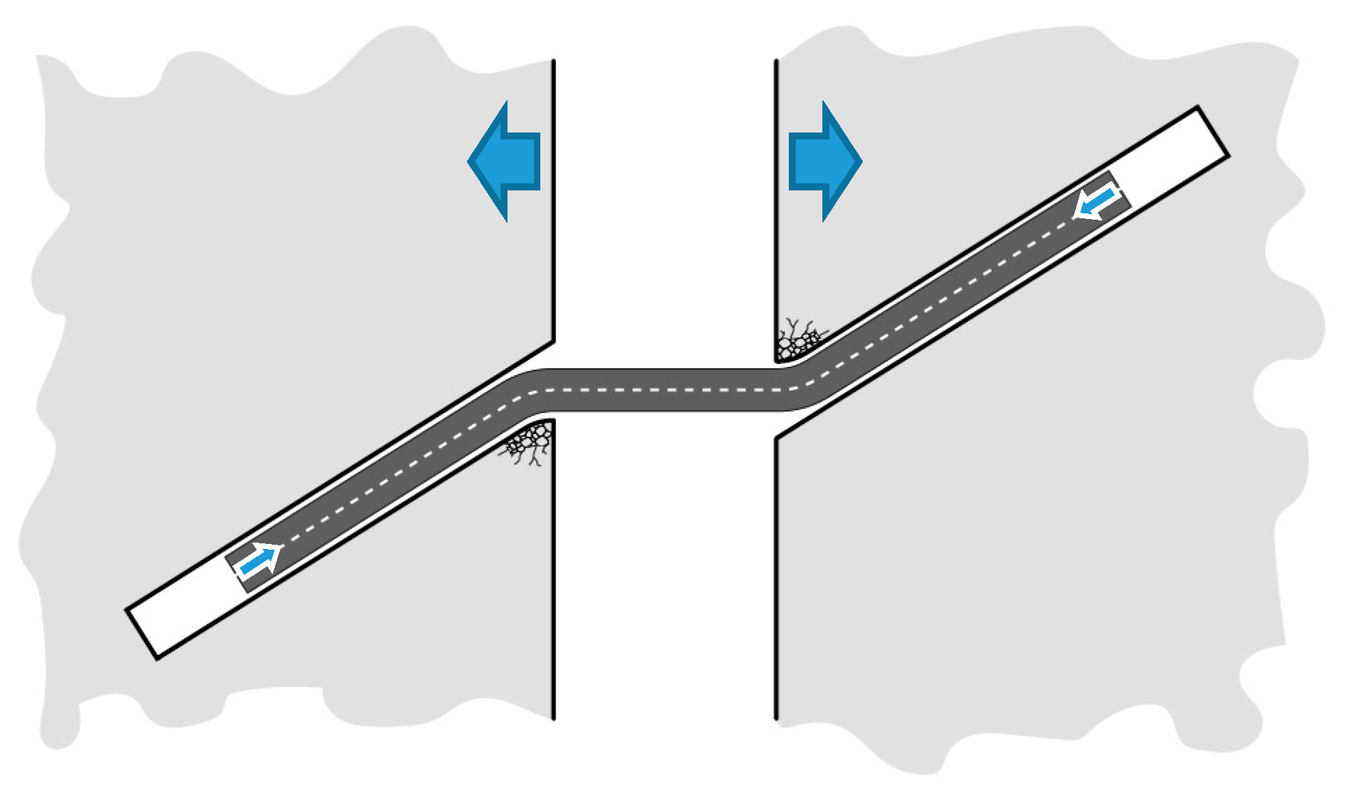
In fiber or needle reinforced concrete the angle between an embedded elongated element and the plane of a crack that intersects that element ranges from 0° to 90°. The probability that the element is perpendicular to the crack surface is very low. In addition, since a crack—particularly a major crack that contributes to the failure of a concrete member—intersects more than one elongated element, the vast majority of the elements are “inclined,” i.e. lie at an angle to the crack surface. When fiber reinforced concrete (FRC) carries increasing external load and a propagating crack intersects an inclined fiber, high tensile strain develops in the fiber in the zone between the crack surfaces, which translates into a high shear stress in the interface between the fiber and cementitious matrix in the zone close to the crack. This shear stress may result in debonding which progresses toward the end of the fiber, after which the fiber, if not anchoraged at the end, will start to move out of its grove at one side of the crack. As shown in Figure 1, in order for an inclined fiber to slip out, it must bend over crack surfaces, which may lead to crumbling of concrete in a relatively small region. Even stiff commercial fibers, such as those made with steel, bend in plastic mode during crack propagation. If during debonding or pull-out the tensile stress at a point in the fiber exceeds its ultimate tensile strength, the fiber will break.
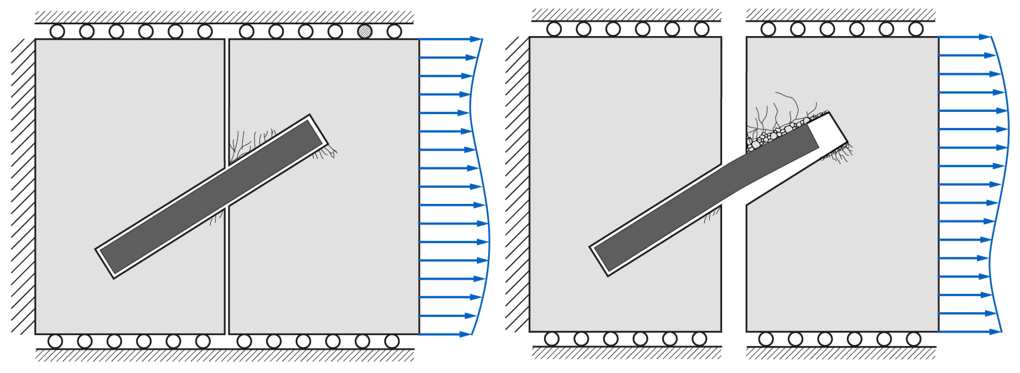
An “ultimate needle” is defined as an elongated element that is fully rigid and infinitely strong in tension and shear. Therefore, ultimate needles do not deform or break. The only way for a concrete crack bridged by an ultimate needle to grow in width is if the concrete encasing the needle crumbles and/or spalls in at least one side of the crack, either progressively or at once. It is not possible to produce ultimate needles since materials that are infinitely strong and rigid do not exist. However, it is possible to create very stiff and strong needles by selecting materials with high Young’s modulus and tensile and flexural strengths and by choosing a large needle cross-section area. Figure 2 illustrates schematically the mechanism of the growth of a crack bridged by a needle. When intersected by a propagating crack, the needle: (1) do not deform in plastic mode or fracture; (2) undergo very small elastic bending. Therefore, the crack opening mechanism will be similar to that described for cracks bridged by ultimate needles. In addition, such needles, due to their large cross-section area, are expected to have specific surface areas much greater than those of concrete fibers and, therefore, do not reduce the workability of fresh concrete significantly.
3.3. Past Studies on Recycling GFRP Waste into Needles for Use in Concrete
In a recent study, GFRP rebar production scrap was cut into needles to be used as discrete reinforcing elements in concrete [28]. The Rebar (RB) needles, had a diameter of 6 mm and a length of 100 mm (Figure 3). Incorporating the RB needles in concrete mixtures to replace volumetrically 5% and 10% of coarse aggregate (1.76% and 3.52% of concrete) led to 22% and 33% increase in the tensile strength of concrete, respectively. In addition, the results of the splitting tensile strength tests showed that the use of the GFRP needles in concrete led to significant increases in the post-peak toughness (energy absorption capacity) of concrete. Figure 4 shows that after peak load concrete specimens incorporating RB needles continued to resist external load up to displacements several times larger than those associated with peak load. Concrete specimens with 5% and 10% needle replacement were, respectively 5% and 9% weaker in compression than the control specimens. The observation of the fresh and harden concretes showed that the RB needles were randomly dispersed in concrete. Although the diameter of the cylinders was only 50% larger than the length of the needles the distribution and orientation of the needles in the cylindrical specimens were relatively random (Figure 5).
In another recent study, GFRP needles with a geometry similar to that of rebar needles were produced by cutting a wind turbine blade using a table saw with a diamond blade [29]. These wind-blade (WB) needles had a length of 100 mm and the majority of them had square cross-sections with the side length of 6 mm. Two types of WB needles were produced; those with smooth and grooved surfaces (Figure 6). The second type of needles had grooves with the width of 1 mm and depth of 2 mm spaced at 17 mm intervals. Reference and needle-incorporated concretes were produced using the same mix proportions as in the study of rebar needles. Various concrete specimens were produced and tested to measure the compressive strength, splitting tensile strength and flexural toughness of concrete. Equivalent flexural strength was calculated as a measure of toughness according to ASTM C1609 [30].
The results show that the incorporation of both plain and grooved WB needles in concrete has an insignificant impact on the compressive strength of concrete. Replacing 5% and 10% of NA with plain WB needles resulted in 1.5% reduction and 0.1% increase in the compressive strength of concrete, respectively. Replacing 5% and 10% of NA with grooved WB needles resulted in 7.2% increase and 4.6% reduction in the compressive strength of concrete, respectively. These changes are within the expected margin of error and do not indicate any beneficial or detrimental impact of the needles on compressive strength of concrete. The better performance of concrete with wind blade needles in compression compared to that of concrete with rebar needles is expected to be due to the more angular surface of wind blade needles.
Test results also show that the splitting tensile strength decreases as a result of incorporating WB needles in concrete. The splitting tensile strength of the concrete with 5% volumetric replacement of NA with plain and grooved needles were 14% and 13% lower than that of the reference concrete. The splitting tensile strength of the concrete with 10% volumetric replacement of NA with grooved needles was 8% lower than that of the reference concrete. The concrete with 10% volumetric replacement of NA with plain needles and the reference concrete (without needles) had the same average splitting tensile strength. These results are in contrast with those from investigating GFRP rebar needles, which as stated earlier, significantly increased the splitting tensile strength of concrete. A resin burn-off test revealed that most of the glass fibers in wind blade needles were not aligned parallel to the axis of the needles. However, in a rebar needle all the fibers are precisely aligned along the axis of the needle. Therefore, the average tensile strength of the wind blade needles was significantly lower than that of rebar needles.
The results of the toughness test showed that the concrete beams incorporating WB needles continued to carry load after the applied load reached its peak value (Figure 7). Replacing 5% and 10% of coarse aggregate by volume with the plain needles led to the increase of average equivalent flexural strength from 1.1 to 14.0 and 32.3, respectively. When grooved needles were used the average equivalent flexural strength for 5% and 10% replacements were 12.6 and 24.7, respectively. The comparison of the test results with a number of past studies on fiber reinforce concrete revealed that the equivalent flexural strength values for the concrete in which 10% of NA is replaced with plain wind blade needles are similar to concretes incorporating (1) steel fibers with volumetric dosages in the range of 0.2–1.0%; (2) glass fibers with volumetric dosages in the range of 1.0–2.0%; and (3) polymeric fibers with volumetric dosages in the range of 0.4–0.5%. Therefore, the reported increases in toughness caused by using needles are significant considering that in most of the wind blade needles glass fibers were transversely-aligned. It is expected that if the wind blade shell was cut along the fibers, so that the fibers in all the needles were longitudinally-aligned, the flexural resistance of the beam specimens would be notably higher.
4. Summary of the Past Studies
Compressive strength, tensile strength and flexural strength are among the main material-level properties of concrete that significantly affect the performance of load bearing structural concrete members and used frequently by structural designers a. The few past studies on recycled GFRP waste incorporated concretes have measured all or some of those properties. The findings from those studies are presented in Table 1. The results show that using recycled GFRP aggregates have a detrimental effect on the mechanical performance of concrete. However, recycled GFRP needles have significant contributions on enhancing the overall mechanical performance of concrete. In particular, GFRP needles with longitudinally aligned fibers enhance the tensile and flexural performance of concrete. However, in the past investigations needles did not enhance the compressive strength of concrete. Needles with round cross-sections tend to cause a small reduction in the compressive strength of concrete.
Figure 8 presents the change (increase or decrease) in the compressive strength and tensile strength of concretes as result of incorporating recycled GFRP aggregates and needles in concrete with different volumetric ratios (the ratios of GFRP volume to concrete volume). In the figure, the diamond shape markers represent the results of testing concrete with GFRP aggregates and the dash markers represent those of concrete with GFRP needles. Although there is not a linear relationship between the GFRP dosage and mechanical performance, the figure clearly shows that increasing the content of recycled GFRP aggregates in concrete leads to the reduction in both the compressive and tensile strengths of concrete. Figure 8 also shows that incorporating small amounts of needles to concrete can have significant (typically positive) impacts on the tensile strength of concrete.
5. Guidance for Future Research
The findings of the past studies on using coarse processed GFRP waste in concrete show that recycled needles can be efficient discrete reinforcing elements. Extensive research needs to be conducted to optimize the production and performance of recycled needles. Needles can be produced from GFRP waste only by means of cutting. Cutting technologies need to be developed that minimize the energy and the time required for producing recycled needles. In addition, experimental and theoretical studies need to be performed to optimize the geometry of needles to achieve the desired properties of concrete in load-carrying members. Durability of recycled GFRP needles embedded in concrete, which is highly alkaline and the long-term mechanical performance of concrete incorporating recycled GFRP needles need to be studied. Finally, assessing the environmental and economic impacts of different alternatives for managing and recycling GFRP waste, in addition to investigating the performance of recycled waste, leads to finding the most efficient and environmentally-conscious practices for the production and reuse of GFRP composite materials.
Acknowledgment
This work was supported by the New York State Energy Research and Development Authority (NYSERDA) under the grant C2CUNY1 by the PowerBridgeNY Program, and by the U.S. National Science Foundation (NSF) under the grant 1701694.
Conflicts of Interest
The authors declare no conflict of interest.
References
- Reynolds, N.; Pharaoh, M. An introduction to composites recycling. In Management, Recycling and Reuse of Waste Composites; Goodship, V., Ed.; Woodhead Publishing: Cambridge, UK, 2010; pp. 3–19. [Google Scholar]
- Witten, E. Composites Market Report 2015 Market Developments, Trends, Outlook and Challenges; Federation of Reinforced Plastics (AVK): Frankfurt, Germany, 2015. [Google Scholar]
- Holmes, M. US demand for fibre reinforced plastic composites to rise. In Reinforced Plastics; Elsevier: Oxford, UK, 2013; Available online: http://www.materialstoday.com/composite-industry/news/us-demand-for-fibre-reinforced-plastic-composites (accessed on 13 February 2018).
- Bank, L.C. Composites for Construction; John Wiley & Sons: Hoboken, NJ, USA, 2006. [Google Scholar]
- Beauson, J.; Lilholt, H.; Brøndsted, P. Recycling solid residues recovered from glass fibre-reinforced composites—A review applied to wind turbine blade materials. J. Reinf. Plast. Compos. 2014, 33, 1542–1556. [Google Scholar] [CrossRef]
- Hardee, C. Improving wind blade manufacturability. Wind Systems, 2 February 2018; 26–30. [Google Scholar]
- Hunt, H.; Wanner, C.; Hensley, J. U.S. Wind Industry Annual Market report—Year Ending 2015; American Wind Energy Association (AWEA): Washington, DC, USA, 2016. [Google Scholar]
- Yazdanbakhsh, A.; Bank, L. A critical review of research on reuse of mechanically recycled FRP production and end-of-life waste for construction. Polymers 2014, 6, 1810–1826. [Google Scholar] [CrossRef]
- Job, S.; Leeke, G.; Mativenga, P.T.; Oliveux, G.; Pickering, S.; Shuaib, N.A. Composite Recycling—Where Are We Now? Composites UK: Hertfordshire, UK, 2016. [Google Scholar]
- Tittarelli, F.; Kawashima, S.; Tregger, N.; Moriconi, G.; Shah, S.P. Effect of GRP by-product addition on plastic and hardened properties of cement mortars. In Proceedings of the 2nd International Conference on Sustainable Construction Materials and Technologies, Ancona, Italy, 28–30 June 2010. [Google Scholar]
- Tittarelli, F.; Shah, S.P. Effect of low dosages of waste GRP dust on fresh and hardened properties of mortars: Part 1. Constr. Build. Mater. 2013, 47, 1532–1538. [Google Scholar] [CrossRef]
- Asokan, P.; Osmani, M.; Price, A.D.F. Assessing the recycling potential of glass fibre reinforced plastic waste in concrete and cement composites. J. Clean. Prod. 2009, 17, 821–829. [Google Scholar] [CrossRef]
- Gu, L.; Ozbakkaloglu, T. Use of recycled plastics in concrete: A critical review. Waste Manag. 2016, 51, 19–42. [Google Scholar] [CrossRef] [PubMed]
- Yazdanbakhsh, A.; Bank, L.C.; Chen, C. Use of recycled FRP reinforcing bar in concrete as coarse aggregate and its impact on the mechanical properties of concrete. Constr. Build. Mater. 2016, 121, 278–284. [Google Scholar] [CrossRef]
- ASTM C33. Standard Specification for Concrete Aggregates; STM International: West Conshohocken, PA, USA, 2013. [Google Scholar]
- Shahria Alam, M.; Slater, E.; Billah, A.M. Green concrete made with RCA and FRP scrap aggregate: Fresh and hardened properties. J. Mater. Civ. Eng. 2013, 25, 1783–1794. [Google Scholar] [CrossRef]
- Fox, T.R. Recycling wind turbine blade composite material as aggregate in concrete. In Department of Industrial and Manufacturing Systems Engineering; Iowa State University: Ames, IA, USA, 2016. [Google Scholar]
- Murrell, S. Concrete Airport Pavements Make a Comeback; New York Construction News; McGraw Hill: New York, NY, USA, 1993. [Google Scholar]
- Roesler, J.R.; Altoubat, S.A.; Lange, D.A.; Rieder, K.-A.; Ulreich, G.R. Effect of synthetic fibers on structural behavior of concrete slabs-on-ground. ACI Mater. J. 2006, 103, 3–10. [Google Scholar]
- Soranakom, C.; Mobasher, B.; Destrée, X. Numerical Simulation of FRC Round Panel Tests and Full-Scale Elevated Slabs; ACI Special Publication: Farmington Hills, MI, USA, 2007; Volume 248. [Google Scholar]
- Bentur, A.; Mindess, S. Fiber Reinforced Cementitious Composites, 2nd ed.; Modern Concrete Technology; Taylor & Francis: New York, NY, USA, 2007. [Google Scholar]
- Behnood, A.; Verian, K.P.; Gharehveran, M.M. Evaluation of the splitting tensile strength in plain and steel fiber-reinforced concrete based on the compressive strength. Constr. Build. Mater. 2015, 98, 519–529. [Google Scholar] [CrossRef]
- Yazdanbakhsh, A.; Altoubat, S.; Rieder, K.A. Analytical study on shear strength of macro synthetic fiber reinforced concrete beams. Eng. Struct. 2015, 100, 622–632. [Google Scholar] [CrossRef]
- Jeknavorian, A.A. Innovations in chemical admixture technology as related to sustainability. In ACI Spring 2012 Convention; American Concrete Institute: Dallas, TX, USA, 2012. [Google Scholar]
- Choi, Y.; Yuan, R.L. Experimental relationship between splitting tensile strength and compressive strength of GFRC and PFRC. Cem. Concr. Res. 2005, 35, 1587–1591. [Google Scholar] [CrossRef]
- Nanni, A. Splitting-tension test for fiber reinforced concrete. ACI Mater. J. 1988, 85, 229–233. [Google Scholar]
- Wafa, F.; Ashour, S. Mechanical properties of high-strength fiber reinforced concrete. ACI Mater. J. 1992, 89, 449–455. [Google Scholar]
- Yazdanbakhsh, A.; Bank, L.C.; Chen, C.; Tian, Y. FRP-Needles as discrete reinforcement in concrete. ASCE J. Mater. Civ. Eng. 2017, 29, 1–9. [Google Scholar] [CrossRef]
- Yazdanbakhsh, A.; Bank, L.C.; Rieder, K.-A.; Tian, Y.; Chen, C. Concrete with discrete slender elements from mechanically recycled wind turbine blades. Resourc. Conserv. Recycl. 2017, 128, 11–21. [Google Scholar] [CrossRef]
- ASTM C1609. Standard Test Method for Flexural Performance of Fiber-Reinforced Concrete (Using Beam with Third-Point Loading); ASTM International: West Conshohocken, PA, USA, 2012. [Google Scholar]
Figure 1.
Fiber pull-out and matrix crumbling during the growth of a crack in concrete.

Figure 2.
(Left) a needle bridging a concrete crack at the outset; (Right) Local failure and crumbling during crack opening.
Figure 2.
(Left) a needle bridging a concrete crack at the outset; (Right) Local failure and crumbling during crack opening.

Figure 3.
Needles obtained by cutting the scrap from producing GFRP rebars [28].
Figure 3.
Needles obtained by cutting the scrap from producing GFRP rebars [28].

Figure 4.
Load-displacement curves from the splitting tensile tests. FRP-NDL-5 and FRP-NDL-10 represent concrete specimens in which 5% and 10% of NA is replaced volumetrically with the rebar (RB) needles.
Figure 4.
Load-displacement curves from the splitting tensile tests. FRP-NDL-5 and FRP-NDL-10 represent concrete specimens in which 5% and 10% of NA is replaced volumetrically with the rebar (RB) needles.

Figure 5.
Distribution of the rebar (RB) needles in a cylindrical specimen tested for splitting tensile strength.
Figure 5.
Distribution of the rebar (RB) needles in a cylindrical specimen tested for splitting tensile strength.
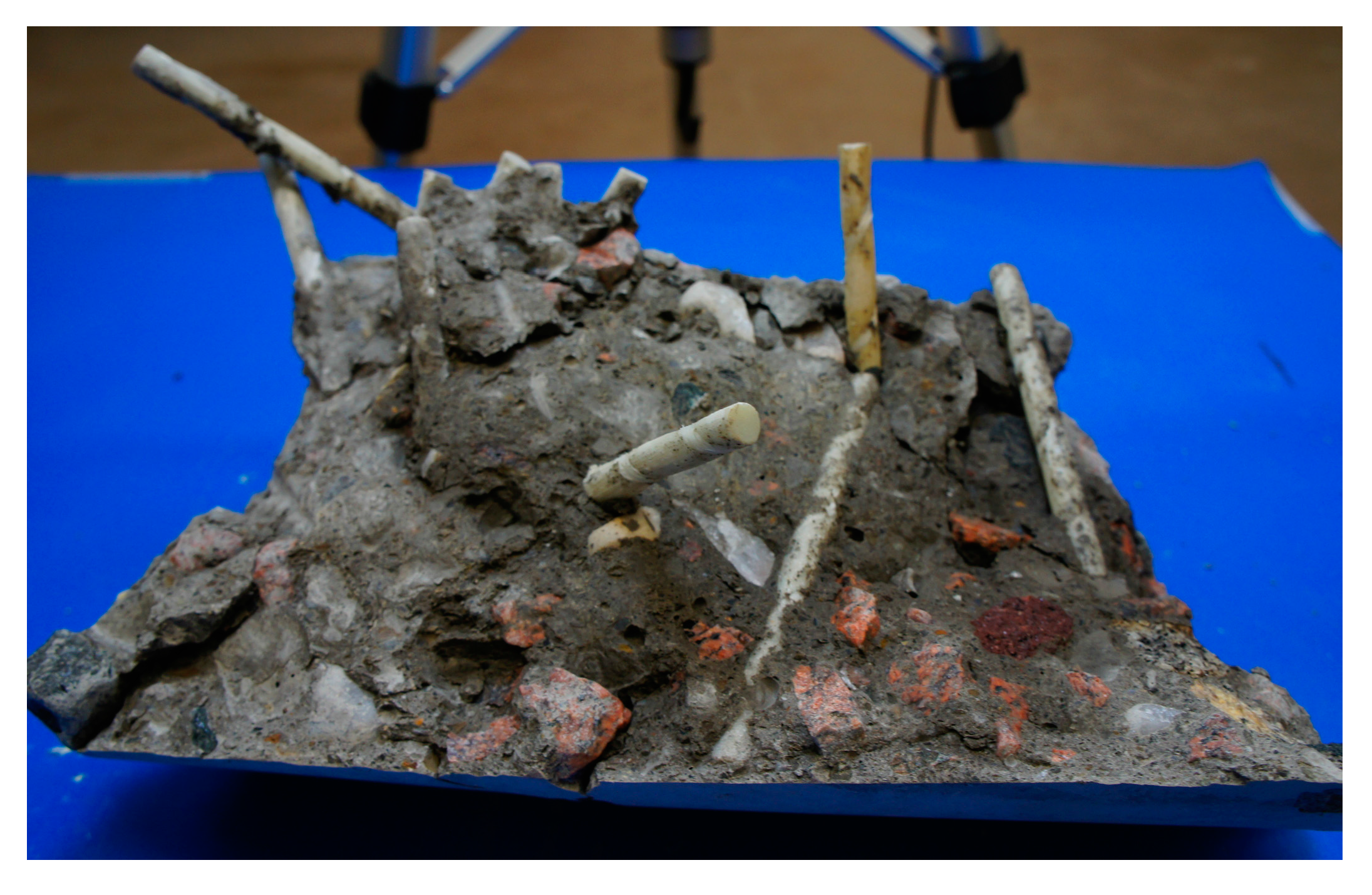
Figure 6.
(a) Plain and (b) grooved wind blade needles obtained from cutting a wind blade shell.
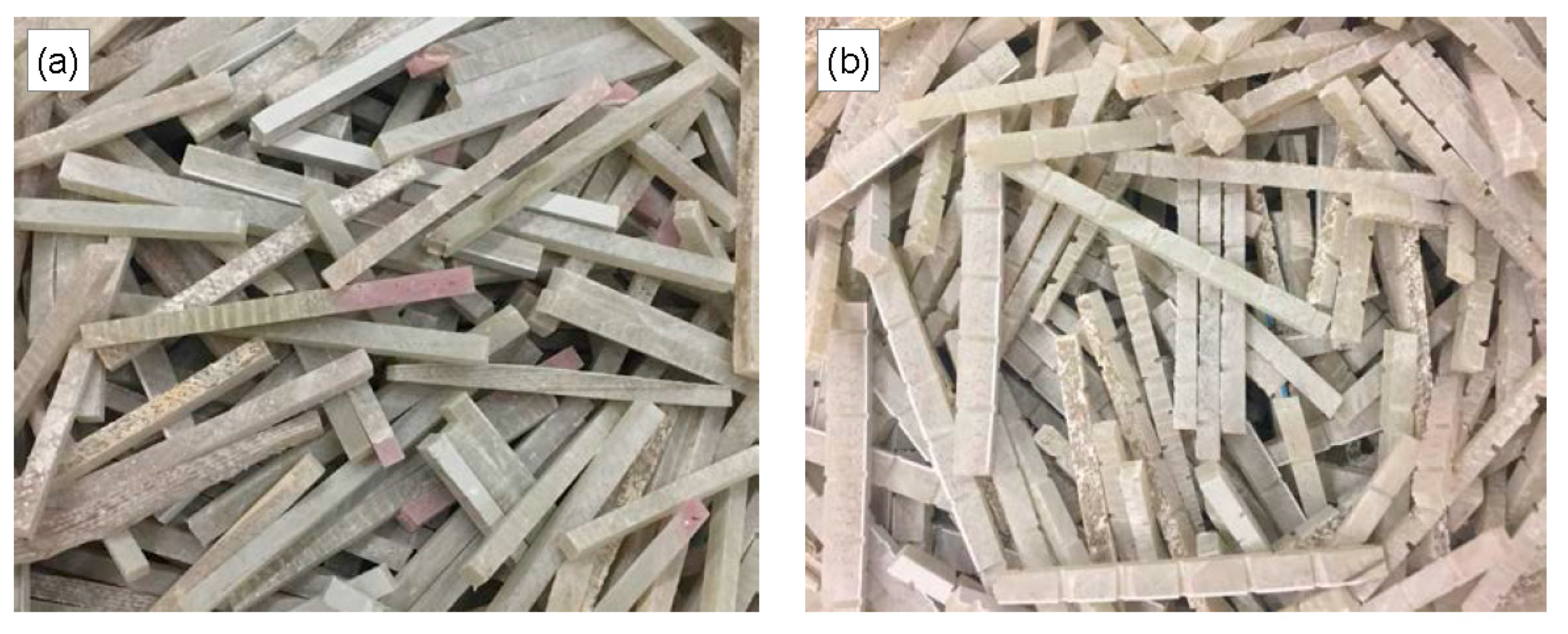
Figure 7.
Load-displacement results from third point bending tests of concrete specimens with (a) plain and (b) grooved needles. The numbers 5 and 10 in the specimen notations represent the volumetric ratios of replacing NA with needles.
Figure 7.
Load-displacement results from third point bending tests of concrete specimens with (a) plain and (b) grooved needles. The numbers 5 and 10 in the specimen notations represent the volumetric ratios of replacing NA with needles.

Figure 8.
Change (increase or decrease) in the (a) compressive strength and (b) splitting tensile strength of concrete as a result of incorporating recycled GFRP aggregates and needles in concrete at different volumetric portions of concrete. The diamond shape markers represent the results of testing concrete with GFRP aggregates and the dash markers represent those of concrete with GFRP needles.


Table 1.
Results from the past studies on the mechanical properties of concrete with GFRP waste.
| Ref. | Element Type | Size mm | Coarse Aggregate Replacement Ratio (Vol.) % | GFRP to Concrete Ratio (Vol.) % | Slump mm | Mpa | Mpa | Flexural Strength MPa |
|---|---|---|---|---|---|---|---|---|
| Alam et al. 2013 [16] | - | - | 0.0 | 0.0 | 160 | 50.03 | 2.32 | 4.13 |
| Flat GRA | sl < 25 | 25.0 | 11.1 | 210 | 31.2 | 2.1 | 2.91 | |
| Flat GRA | sl < 25 | 50.0 | 22.0 | 220 | 24.47 | 2.53 | 2.38 | |
| Fox, 2016 [17] | - | - | 0.0 | 0.0 | - | 40.5 | - | - |
| GRA | sl = 13 | 50.0 | 7.8 | - | 22.3 | - | - | |
| GRA | sl = 13, 25 | 50.0 | 7.8 | - | 22.1 | - | - | |
| GRA | sl = 25 | 50.0 | 7.8 | - | 22.6 | - | - | |
| GRA | sl = 25 | 25.0 | 3.9 | - | 31.2 | - | - | |
| GRA | sl = 25 | 37.5 | 5.9 | - | 25.0 | - | - | |
| GRA | sl = 25 | 50.0 | 7.8 | - | 22.1 | - | - | |
| GRA | sl = 25 | 32.5 | 5.1 | - | 39.2 | - | - | |
| GRA | sl = 25 | 32.5 | 5.1 | - | - | 3.8 | - | |
| Yazdanb-akhsh et al. 2016 [14] | - | - | 0.0 | 0.0 | - | 37.5 | 4.0 | - |
| GRA | D = 19,25 | 40.0 | 15.4 | - | 32.8 | 3.0 | - | |
| GRA | D = 6,10,13,19,25 | 100.0 | 38.5 | - | 29.5 | 2.6 | - | |
| - | - | 0.0 | 0.0 | - | 46.3 | 4.5 | - | |
| GRA | D = 19, 25 | 40.0 | 16.0 | - | 40.4 | 4.0 | - | |
| GRA | D = 6,10,13,19,25 | 100.0 | 40.0 | - | 36.6 | 3.6 | - | |
| Yazdanb-akhsh et al. 2017 [28] | - | - | 0.0 | 0.0 | 70 | 40.2 | 3.42 | - |
| GRA | D = 6,10,13,19 | 5.0 | 1.8 | 70 | 37.9 | 3.06 | - | |
| GRA | D = 6,10,13,19 | 10.0 | 3.5 | 65 | 38.9 | 3.42 | - | |
| Needle | D = 6 L = 100 | 5.0 | 1.8 | 75 | 38.0 | 4.18 | - | |
| Needle | D = 6 L = 100 | 10.0 | 3.5 | 70 | 36.7 | 4.55 | - | |
| Yazdanb-akhsh, 2018 [29] | - | - | 0.0 | 0.0 | 125 | 36.0 | 3.35 | 5.0 |
| 160 | ||||||||
| Plain needle | L = 100 | 5.0 | 1.8 | 115 | 35.5 | 2.89 | 4.5 | |
| sl = 6 | 110 | |||||||
| Plain needle | L = 100 | 10.0 | 3.5 | 125 | 36.1 | 3.35 | 4.6 | |
| sl = 6 | 110 | |||||||
| Grooved needle | L = 100 | 5.0 | 1.8 | 115 | 38.6 | 2.91 | 5.0 | |
| sl = 6 | 120 | |||||||
| Grooved needle | L = 100 | 10.0 | 3.5 | 110 | 34.4 | 3.09 | 4.7 | |
| sl = 6 | 95 |
Notes: L represents length, D represents diameter, sl is the approximate average side length of cubic and rectangular sections, and are the 28-day compressive and tensile strengths of concrete.
© 2018 by the authors. Licensee MDPI, Basel, Switzerland. This article is an open access article distributed under the terms and conditions of the Creative Commons Attribution (CC BY) license (http://creativecommons.org/licenses/by/4.0/).
Share and Cite
MDPI and ACS Style
Yazdanbakhsh, A.; Bank, L.C.; Tian, Y. Mechanical Processing of GFRP Waste into Large-Sized Pieces for Use in Concrete. Recycling 2018, 3, 8. https://doi.org/10.3390/recycling3010008
AMA Style
Yazdanbakhsh A, Bank LC, Tian Y. Mechanical Processing of GFRP Waste into Large-Sized Pieces for Use in Concrete. Recycling. 2018; 3(1):8. https://doi.org/10.3390/recycling3010008
Chicago/Turabian StyleYazdanbakhsh, Ardavan, Lawrence C. Bank, and Yuan Tian. 2018. "Mechanical Processing of GFRP Waste into Large-Sized Pieces for Use in Concrete" Recycling 3, no. 1: 8. https://doi.org/10.3390/recycling3010008