
Memory Efficient VLSI Implementation of Real-Time Motion Detection System Using FPGA Platform


1
CSIR—Central Electronics Engineering Research Institute (CSIR-CEERI), Pilani 333031, Rajasthan, India; Academy of Scientific & Innovative Research (AcSIR), India
2
Electronic Science Department, Kurukshetra University, Kurukshetra 136119, Haryana, India
*
Author to whom correspondence should be addressed.
J. Imaging 2017, 3(2), 20; https://doi.org/10.3390/jimaging3020020
Submission received: 25 February 2017
/
Revised: 3 June 2017
/
Accepted: 5 June 2017
/
Published: 7 June 2017
Abstract
:Motion detection is the heart of a potentially complex automated video surveillance system, intended to be used as a standalone system. Therefore, in addition to being accurate and robust, a successful motion detection technique must also be economical in the use of computational resources on selected FPGA development platform. This is because many other complex algorithms of an automated video surveillance system also run on the same platform. Keeping this key requirement as main focus, a memory efficient VLSI architecture for real-time motion detection and its implementation on FPGA platform is presented in this paper. This is accomplished by proposing a new memory efficient motion detection scheme and designing its VLSI architecture. The complete real-time motion detection system using the proposed memory efficient architecture along with proper input/output interfaces is implemented on Xilinx ML510 (Virtex-5 FX130T) FPGA development platform and is capable of operating at 154.55 MHz clock frequency. Memory requirement of the proposed architecture is reduced by 41% compared to the standard clustering based motion detection architecture. The new memory efficient system robustly and automatically detects motion in real-world scenarios (both for the static backgrounds and the pseudo-stationary backgrounds) in real-time for standard PAL (720 × 576) size color video.
1. Introduction
Motion detection, one of the fundamental and most important problem of computer vision, plays a very important role in the realization of a complete vision based automated video surveillance system for automatic scene analysis, monitoring, and generation of security alerts based on relevant motion in a video scene. Motion detection in a video scene provides significant and important information related to movement and presence of objects in a scene. This information helps in achieving higher level objectives such as target detection and segmentation, target tracking, object recognition, scene analysis, etc. Furthermore, real-time motion detection allows more efficient hard disk storage by only archiving video frames where a motion threshold is crossed. By selecting the frames of relevant motion, it also reduces the communication and processing overheads (which are key implementation issues for an automated video surveillance system) in a remote video surveillance scenario.
The problem of motion detection can be stated as “given a set of images of the same scene taken at several different times, the goal of motion detection is to identify the set of pixels that are significantly different between the last image of the sequence and the previous images” [1]. The identified pixels comprise the motion mask. One of the key issues is that the motion mask should not contain “unimportant” or “nuisance” forms of motion.
The importance of motion detection for designing an automated video surveillance system can be gauged from the availability of a large number of robust and complex algorithms that have been developed to-date, and the even larger number of articles that have been published on this topic so far. The simplest approach for motion detection is the frame differencing method in which motion detection can be achieved by finding the difference of the pixels between two adjacent frames. If the difference is higher than a threshold, the pixel is identified as foreground otherwise background. The threshold is chosen empirically. Different methods and criteria for choosing the threshold have been surveyed and their comparative results have been reported in the literature [2,3,4]. Researchers have reported several motion detection methods that are closely related to simple differencing, e.g., change vector analysis [5,6,7], image rationing [8], and frame differencing using sub-sampled gradient images [9]. The simplicity of frame differencing based approaches comes at the cost of motion detection quality. For a chosen threshold, simple differencing based approaches are unlikely to outperform the more advanced algorithms proposed for real-world surveillance applications. There are several other motion detection techniques such as predictive models [10,11,12,13,14], adaptive neural network [15], and shading models [16,17,18]. A comprehensive description and comparative analysis of these methods has been presented by Radke et al. [1].
Practical real-world video surveillance applications demand a continuous updating of the background frame to incorporate any permanent scene change, i.e., if a pixel has remained stationary for a sufficient number of frames, it must be copied into the background frame, for example light intensity changes in day time must be a part of the background. For this purpose, several researchers [19,20] have described adaptive background subtraction techniques for motion detection. They have used single Gaussian Density Function to model the background. These algorithms succeed in learning and refining the single background model. They are capable of handling illumination changes in a scene and are well suited for stationary background scenarios.
Due to pseudo-stationary nature of the background in real-world scenes, assuming that background is perfectly stationary for surveillance applications is a serious flaw. For example, in a real-world video scene, there may be swaying branches of trees, moving tree leaves in windows of rooms, moving clouds, the ripples of water on a lake, or moving fan in the room. These are small repetitive motions (typically not important) and so should be incorporated into background. The single background model based approaches mentioned above are incapable of correctly modeling such pseudo-stationary backgrounds. Stauffer and Grimson [21] recognized that these kinds of pseudo-stationary backgrounds are inherently multi-model and hence they developed the technique of an Adaptive Background Mixture Models, which models each pixel by a mixture of Gaussians. According to this method, every incoming pixel value is compared against the existing set of models at that location to find a match. If there is a match, the parameters of matched model are updated and the incoming pixel is classified as background pixel. If there is no match, the incoming pixel is motion pixel and the least-likely model (model having minimum weighted Gaussian) is discarded and replaced by a new one with incoming pixel as its mean value and a high initial variance value. However, maintaining these mixtures for every pixel is an enormous computational burden and results in low frame rates when compared to previous approaches. Butler et al. [22] proposed a new approach, similar to that of Stauffer and Grimson [21], but with a reduced computational complexity. The processing, in this approach, is performed on YCrCb video data format, but it still requires many floating point computations and needs large amounts of memory for storing background models.
Within computer vision community, a myriad of algorithms exist for motion detection, unfortunately, most of these are not suitable for real-time processing and at the same time require a huge amount of storage space (memory) for storing multiple background models. Because of this, the objective of performing motion detection in real-time on limited computational resources for developing standalone automated video surveillance system proves to be a major bottleneck.
Furthermore, it is important to note that motion detection is one component of a potentially complex automated video surveillance system, intended to be used as a standalone system. Therefore, in addition to being accurate and robust, a successful motion detection technique must also be economical in the use of computational resources on FPGA development platform. This is because many other complex algorithms of an automated video surveillance system also run on the same FPGA platform. In order to address this problem of reducing the computational complexity, Chutani and Chaudhury [23] proposed a block-based clustering scheme with a very low complexity for motion detection. On the one hand, this scheme is robust enough for handling pseudo-stationary nature of background, and on the other it significantly lowers the computational complexity. To achieve the real-time performance, a dedicated VLSI architecture has been designed for this clustering based motion detection scheme by Singh et al. [24]. After analyzing the synthesis results, it is found that proposed architecture for clustering based motion detection scheme utilizes 168 36Kb Block RAMs out of the total 298 (approximately 56%) Block RAMs are on a Xilinx ML510 (Virtex-5 FX130) FPGA board. This implies that a large amount of on-chip memory (Block RAMs) is utilized by motion detection system, which is only one of the potentially complex and important components of an automated video surveillance system. This is a major concern for designing of a complete standalone automated video surveillance system which requires the implementation of multiple hardware architectures on the same FPGA platform—as not much FPGA Block RAMs are left for other complex operations such as focused region extraction, object tracking, and video history generation. For this reason, further emphasis needs to be given to the minimization of memory requirements of clustering-based motion detection algorithm and architecture without compromising on accuracy and robustness of motion detection.
To overcome this problem, based on certain key observation and associated modification in original clustering-based motion detection algorithm, we have proposed a memory-efficient motion detection scheme and designed its dedicated memory-efficient VLSI architecture. Memory requirement of the proposed architecture is reduced by 41% compared to standard clustering based motion detection architecture [24]. We have integrated the implemented memory efficient VLSI architectural modules with the camera interface module and DVI display controller and a working prototype system has been developed using Xilinx ML510 (Virtex-5 FX130T) FPGA development platform for real-time motion detection in a video scene. The system so developed is capable of detecting relevant motion in real-time and can filter the frames of interest for remote surveillance scenarios based on visual motion in a scene. The implemented memory-efficient system can be used as a component of a complete standalone automated video surveillance system.
In short, the contributions of this work over the existing literature are threefold. First, we have proposed and designed a memory efficient hardware implementation friendly motion detection algorithm. Further, its functionality has been verified through software implementation using C/C++ programming language. Second, for the proposed algorithm, we have designed and synthesized a VLSI architecture capable of providing real-time performance. Finally, we have integrated the implemented architectural modules with the camera interface module and DVI display controller and a working prototype system has been developed for real-time motion detection in a video scene.
2. Proposed Motion Detection Algorithm
The original clustering-based motion detection algorithm [23] and its VLSI architecture [24] were re-looked and the memory analysis of the implemented architecture was carried out. There are three memory components in the proposed architecture: Input Buffer Memory, Output Buffer Memory, and Parameter Memory (Centroid Memory and Frame Number Memory). Each of the two output buffer memory modules stores one-bit output of 4 × 4 pixel block for 4 rows. This requires only 180 bits for each memory. Therefore, both the output memory modules are implemented using LUTs instead of Block RAMs and thus utilizes FPGA slices and not the on-chip memory. The input buffer memory requires eight 36-Kb Block RAMs. The Parameter memory requires 160 36-Kb Block RAMs (96 36-Kb Block RAMs for Centroid Parameter memory and 64 36-Kb Block RAMs for Frame Number Parameter Memory). As output buffer memory is implemented using FPGA slice LUTs so there is no scope of Block RAM reduction for this memory component. Therefore, we need to focus on minimizing the memory requirements for Input Buffer Memory and Parameter Memory. As Input Buffer Memory, requires only eight 36-Kb Block RAMs, effect of optimizations/improvements in Input Buffer Memory will be very small on overall memory requirements. On the other hand, the optimizations/reduction in Parameter Memory will significantly affect overall memory requirements.
Furthermore, based on prior VLSI design experience and computer vision algorithm knowledge, we observed that the optimizations of Input Buffer Memory will come through architectural modifications, while the optimizations/reduction in Parameter Memory will come through algorithmic modifications. A new architecture has also been proposed for Input Buffer Memory for enabling streaming video processing which utilizes only three 36-Kb Block RAMs and four registers (each of 24-bit width) as against the earlier requirement of eight 36-Kb Block RAMs for Input Buffer Memory.
Therefore, in order to reduce the parameter memory size we proposed a new algorithm based on certain observations and modifications in the original clustering-based motion detection scheme [23]. It has been found that the proposed modifications have resulted in 40% reduction in Parameter Memory requirements. The algorithm is proposed and designed aiming at reduction in the memory requirements without compromising on the robustness and accuracy of motion detection.
By proposing these architectural and algorithmic modifications, overall 41% reduction has been achieved in total on-chip memory requirements as compared to the architecture designed and implemented for the original clustering-based motion detection scheme. This reduction in memory requirements is very significant.
In the hardware architecture implemented and discussed in [24] for original clustering based motion detection scheme, almost 95% of the total utilized Block RAMs (160 36-Kb Block RAMs out of 168 utilized 36-Kb Block RAMs) are used by parameter memory for storing Centroid values and Frame Number values of four clusters (used for modeling the pseudo-stationary backgrounds). The parameter memory size is directly proportional to the size of the cluster group, block size, and video frame size. Therefore, for given standard PAL (720 × 576) size color video streams, parameter memory size can be reduced either by reducing the number of clusters from four to three or by increasing the 4 × 4 pixel block size to a larger block size. However, Chutani and Chaudhury [23] had chosen to select a cluster size of four clusters and block size of 4 × 4 pixels because empirically they had found that these values result in a good balance between accuracy and computational complexity of their algorithm. Therefore, reducing cluster size or increasing block size will result in the degradation of accuracy and robustness of the clustering based motion detection scheme. In the first case, if the number of clusters is reduced to three then the algorithm’s background model used to capture pseudo-stationary changes/movements becomes weak and the algorithm becomes more sensitive to pseudo-stationary background changes, resulting in false relevant motion detection outputs for pseudo-stationary background changes. In the second case, for larger block sizes, the system becomes less sensitive to relevant motions in smaller areas in a video scene. Therefore, none of the above two techniques can be used to reduce parameter memory size as the objective is to reduce parameter memory size without compromising on the accuracy and the robustness of motion detection. For this reason, we re-analyzed the original clustering based motion detection algorithm [23] and the following observations resulted.
The background related information in the clustering-based motion detection algorithm is stored and updated in parameter memory having two components viz. Centroid Memory and Frame Number Memory. Each Centroid Memory location contains four Centroid values (corresponding to four clusters), which contain the background color and intensity related information. Each Frame Number Memory location stores four Frame Number values (corresponding to four clusters) which are used to keep the record of update or replacement history of the Centroid value, i.e., for the particular 4 × 4 pixel block when (at what time or for what Frame Number) the cluster Centroid value is updated or replaced. Now, the important observation is that during the cluster update (in the case a matching cluster is found) or cluster replacement (in the case no matching cluster is found) the actual time or frame number when the cluster is updated or replaced is not necessarily required. During cluster update, the matching cluster number is required (i.e., first or second or third or fourth), not the actual value of the Frame Number. In the case of cluster replacement, the oldest cluster number (which has not been updated for the longest period of time) is required. This implies that there is no need of storing the complete Frame Number value. An index value is sufficient to maintain the update or replacement history of a cluster, which implies that it is the newest cluster (most recently updated or replaced), the second newest cluster, the second oldest cluster, or the oldest cluster (which has not been updated for the longest period of time). It further implies that a two-bit index value is sufficient to record this information for four clusters. This reduces the 16-bit wide Frame Number Memory to two-bit wide memory. This saves 56 36-Kb Block RAMs for PAL resolution color videos.
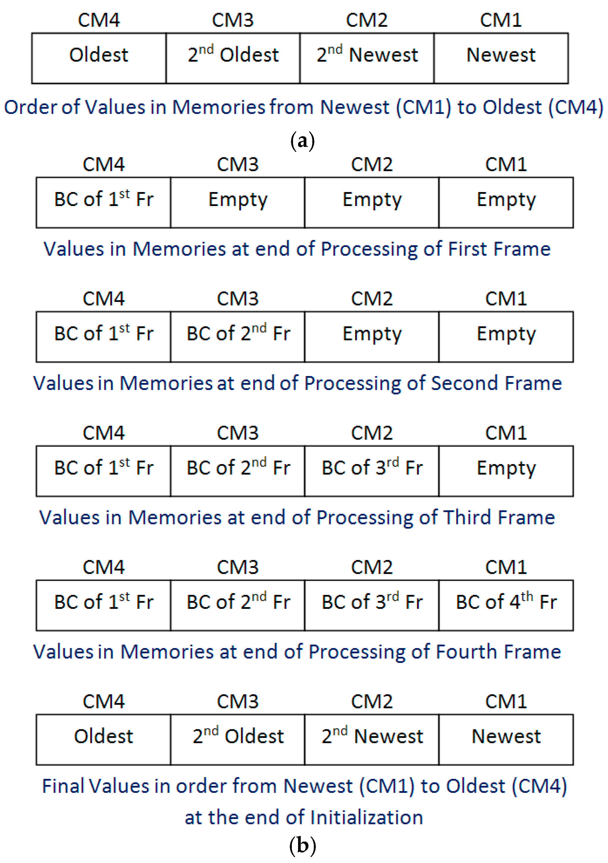
It is further observed that the record of cluster update or cluster replacement history can be maintained by using appropriate logic without even using two-bit index value. In order to store Centroid value of four clusters, there are four Centroid memories, i.e., CM1, CM2, CM3, and CM4. Consider that, the first memory CM1 always contains the newest Centroid value, i.e., the Centroid value of the cluster which is most recently updated (it is considered as Cluster 1), the second memory CM2 always contains the second newest Centroid value, i.e., Centroid value of the cluster which has been updated just before most recently updated cluster (it is considered as Cluster 2), the third memory CM3 always contains the second oldest Centroid value, i.e., the Centroid value of the cluster which has been updated just after oldest cluster (it is considered as Cluster 3), and the fourth memory CM4 always contains the oldest Centroid value, i.e., the Centroid value of the cluster which has not been updated for the longest period of time (it is considered as Cluster 4). These considerations are shown in Figure 1a. The algorithmic steps for performing motion detection based on these assumptions are discussed next.
The main steps of the proposed memory efficient clustering based motion detection scheme are Block Centroid Computation, Cluster Group Initialization, Cluster Matching, Cluster Updating, Cluster Replacement, and Classification. Three steps of the proposed algorithm, i.e., Block Centroid Computation, Cluster matching, and Classification are the same as that in the case of original clustering based scheme. The remaining three steps of the proposed memory efficient motion detection algorithm, i.e., Cluster Group Initialization, Cluster Updating, and Cluster Replacement are explained below.
Cluster Group Initialization is performed during first four frames. In the first frame, the fourth cluster of each 4 × 4 pixel block is initialized with its Centroid set to Block Centroid of the corresponding block of the first frame and therefore, it is stored in Centroid Memory CM4, as this is going to be the oldest value at the end of the Cluster Group Initialization process. In the second frame, the third cluster of each 4 × 4 pixel block is initialized with its Centroid set to Block Centroid of the corresponding block of the second frame and therefore, it is stored in Centroid Memory CM3, as this is going to be the second oldest value at the end of the Cluster Group Initialization process. In the third frame, the second cluster of each 4 × 4 pixel block is initialized with its Centroid set to Block Centroid of the corresponding block of the third frame and therefore, it is stored in Centroid Memory CM2, as this is going to be the second newest value at the end of the Cluster Group Initialization process. In the fourth frame, the first cluster of each 4 × 4 pixel block is initialized with its Centroid set to Block Centroid of the corresponding block of the fourth frame and, therefore, it is stored in Centroid Memory CM1, as this is going to be the newest value at the end of the Cluster Group Initialization process. At the end of initialization process, the Centroid Memories (CM1, CM2, CM3, and CM4) contains the Centroid values in order from the newest (CM1) to the oldest (CM4). The complete process is shown in Figure 1b.
After initialization (in initial four frames), for all subsequent frames, the motion detection is performed. During motion detection either of the two processes (i.e., Cluster Updating process or Cluster Replacement process) is performed. Therefore, the objective is either to update the Centroid value or to replace the Centroid value in the Centroid memories and maintain the order of newest value, second newest value, second oldest value, and oldest value in CM1, CM2, CM3, and CM4 respectively.
If a matching cluster is found (i.e., the Minimum Centroid Difference is less than the threshold) within the cluster group then the matching cluster is updated. For this purpose, the Centroid value of the matching cluster is updated with the average value of the matching cluster Centroid value and incoming current Block Centroid value. The matching cluster can be any one of the four clusters, i.e., first or second or third or fourth.
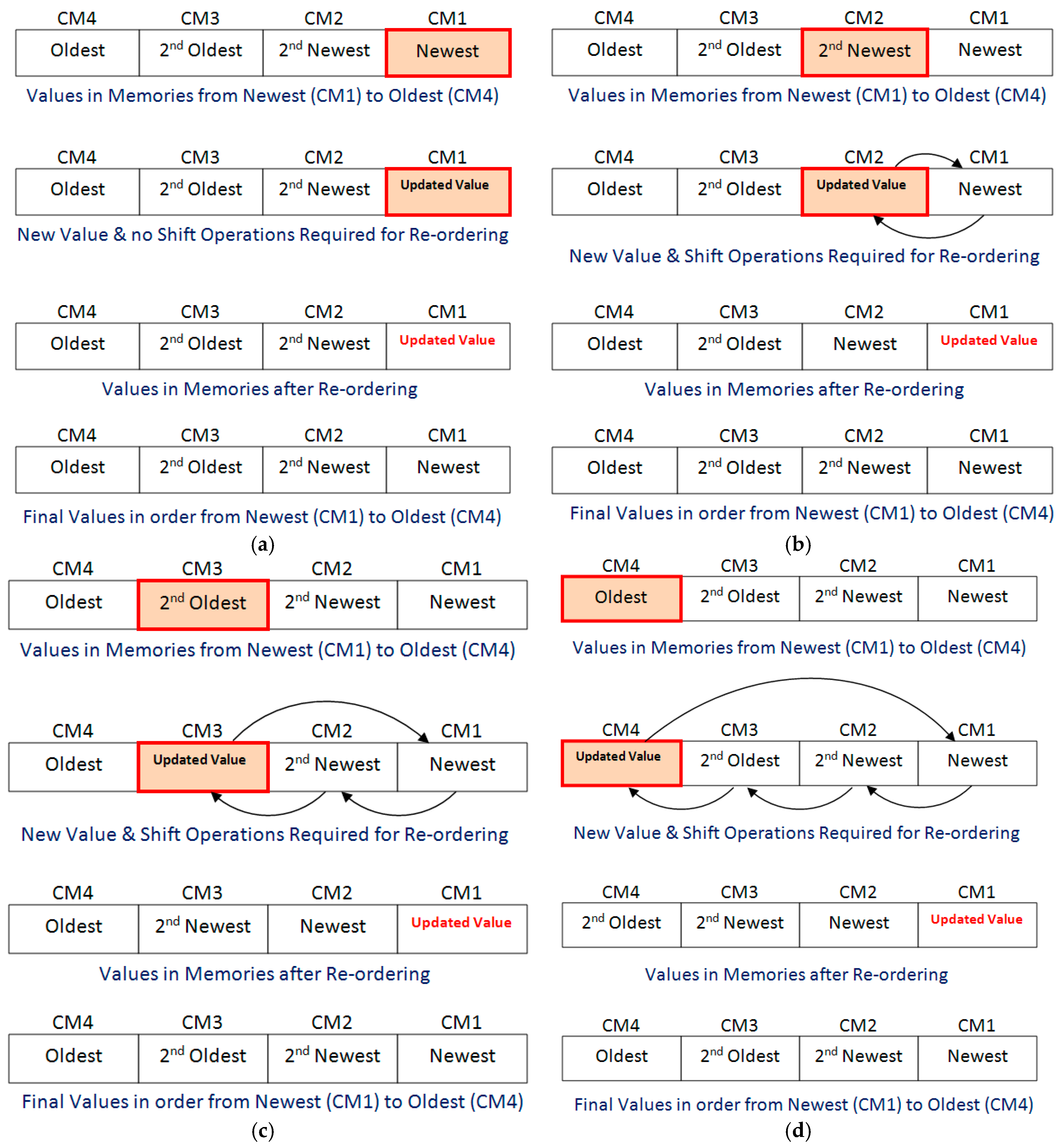
Consider the first case of Cluster Updating, i.e., matching cluster is the first cluster. In this case, Centroid memory CM1 is updated with the average value of the matching cluster Centroid value and incoming current Block Centroid value. The updated value in CM1 is the newest value. Therefore, no re-ordering of other memories values is required for arraigning the values in order of newest value, second newest value, second oldest value, and oldest value in CM1, CM2, CM3, and CM4 respectively. The process is explained in Figure 2a.
Consider the second case of Cluster Updating, i.e., matching cluster is the second cluster. In this case, Centroid memory CM2 is updated with the average value of the matching cluster Centroid value and incoming current Block Centroid value. The updated value in CM2 is the newest value. Therefore, the re-ordering of other memories values is required for arraigning the values in order of newest value, second newest value, second oldest value, and oldest value in CM1, CM2, CM3, and CM4, respectively. For this purpose, the value of CM1 and updated value in CM2 are interchanged. During interchanging, the new updated value in CM2 (which is latest updated value) is moved to CM1 and the old value of CM1 is moved to CM2. The values of CM3 and CM4 remain unchanged. The process is explained in Figure 2b. At the end of cluster updating process, the values are in the order of newest (CM1) to oldest (CM4).
Consider the third case of Cluster Updating, i.e., matching cluster is the third cluster. In this case, Centroid memory CM3 is updated with the average value of the matching cluster Centroid value and incoming current Block Centroid value. The updated value in CM3 is the newest value. Therefore, the re-ordering of other memories values is required for arraigning the values in order of newest value, second newest value, second oldest value, and oldest value in CM1, CM2, CM3, and CM4, respectively. For this purpose, the cluster Centroid values in CM1 and CM2 are shifted to CM2 and CM3, respectively, and these become older by one step. The latest updated value of CM3 is moved to CM1. The value of CM4 remains unchanged. The process is explained in Figure 2c. At the end of cluster updating process, the values are in the order of newest (CM1) to oldest (CM4).
Consider the last/fourth case of Cluster Updating, i.e., matching cluster is the fourth cluster. In this case, Centroid memory CM4 is updated with the average value of matching cluster Centroid value and incoming current Block Centroid value. The updated value in CM4 is the newest value. Therefore, the re-ordering of other memories values is required for arraigning the values in order of newest value, second newest value, second oldest value, and oldest value in CM1, CM2, CM3, and CM4 respectively. For this purpose, the cluster Centroid values in CM1, CM2, and CM3 are shifted to CM2, CM3, and CM4, respectively and these become older by one step. The latest updated value of CM4 is moved to CM1. The process is explained in Figure 2d. At the end of cluster updating process, the values are in the order of newest (CM1) to oldest (CM4).
If no matching cluster is found (i.e., the Minimum Centroid Difference is greater than the threshold) within the cluster group then oldest cluster is replaced. For this purpose, the oldest cluster which has not been updated for the longest period of time, i.e., fourth cluster (Centroid value in Centroid memory CM4) is replaced with a cluster having Centroid value set to incoming current Block Centroid value. The new value in CM4 is the newest value as it is replaced most recently. Therefore, the re-ordering of other memories values is required for arraigning the values in order of newest value, second newest value, second oldest value, and oldest value in CM1, CM2, CM3, and CM4, respectively. For this purpose, the cluster Centroid values in CM1, CM2, and CM3 are shifted to CM2, CM3, and CM4, respectively, and these become older by one step. The latest (new) value of CM4 is moved to CM1. The process is explained in Figure 3. At the end of the cluster replacement process, the values are in the order of newest (CM1) to oldest (CM4).
Thus, at the end of any of the processes, i.e., Cluster Group Initialization, Cluster Updating, or Cluster Replacing, the four Centroid memories CM1, CM2, CM3, and CM4 contain values in the order of newest value, second newest value, second oldest value, and oldest value in CM1, CM2, CM3, and CM4, respectively. This process is performed for all the blocks in every incoming frame and thus maintains the record of history of clusters without storing the frame number or the index value. In other words, it keeps track of newest cluster (most recently updated or replaced), second newest cluster, second oldest cluster, or oldest cluster (which has not been updated for the longest period of the time) and does not require frame number or index value. Only this much information about the history of the clusters (i.e., newest cluster, second newest cluster, second oldest cluster, and oldest cluster) is required for performing clustering based motion detection. The proposed novel scheme is thus successful in substantially reducing the memory requirement of clustering based motion detection scheme, without any loss of accuracy in motion detection. The resulting reduction in Parameter memory size is 40% as compared to the original clustering based motion detection scheme [23] with no loss of accuracy or robustness of the system.
In order to reduce the memory requirement of motion detection algorithm, without negatively impacting the quality of processed videos, it is important to accurately evaluate the proposed algorithm against original clustering-based motion detection algorithm on video streams of different real-world scenarios.
For this purpose, the standard clustering based algorithm and proposed memory efficient algorithm have been programmed in C/C++ programming language. For running the code, a Dell Precision T3400 workstation (with Windows XP operating system, quad-core Intel® CoreTM2 Duo Processor with 2.93 GHz Operating Frequency, and 4 GB RAM) was used. Open Computer Vision (OpenCV) libraries were used in the code for reading video streams (either stored or coming from camera) and displaying motion detection results. Effect of removing the frame number from parameter memory was evaluated on test bench videos taken from surveillance cameras. The selected video streams have a resolution of 720 × 576 pixels (PAL size) and five-minute duration.
Figure 4 visually compares the results for both the motion detection algorithms (proposed and original) for different indoor and outdoor conditions with pseudo-stationary backgrounds. In Figure 4a, moving fan in background is present, while, in Figure 4b, moving leaves of trees are present. Top row shows the original frames extracted from video streams. Second row shows the motion detection results obtained from the original clustering based algorithm and the third row shows the motion detection results obtained from the proposed memory efficient clustering based algorithm for respective frames. To compare the results, pixel-by-pixel difference of second and third row images has been taken and it gives black images (fourth row). This indicates that the proposed memory efficient algorithm produces same motion detection results as original clustering based motion detection algorithm without any loss of accuracy and robustness but with 40% reduction in memory requirement. The frame rate for software-based implementation of memory efficient proposed motion detection algorithm is five frames per second (fps) for PAL (720 × 576) resolution color videos.
For a mathematical proof, for every frame of each video stream, the mean square error (MSE) is calculated. MSE is a common measure of quality of video and is equivalent to other commonly used measures of quality. For example, the peak signal-to-noise ratio (PSNR) is equivalent to MSE [25]. Some researchers measure the number of false positives (FP) and false negatives (FN) whose sum is equivalent to the MSE [26]. MSE is defined as
In the above equation, IORIGINAL (m, n) is the motion detected binary output image produced by running of the software (C/C++) implementation of original clustering based algorithm, while IPROPOSED (m, n) is the motion detected binary output image produced by running of the software (C/C++) implementation of proposed memory efficient clustering based algorithm. M is the number of rows in a video frame, i.e., 576 and N is the number of columns in a video frame, i.e., 720.
As the motion detection outputs are binary images, therefore, the square of the difference between IORIGINAL (m, n) and IPROPOSED (m, n) has only two possible values: “1” if the pixel has different values in IORIGINAL and IPROPOSED and “0” if the pixel has same values. As a result of this MSE is equivalent to the ratio of the number of pixels which are different in IPROPOSED with respect to IORIGINAL to the total number of pixels in a video frame.
The computed MSE for every frame of all the test bench videos is zero and it confirms that the proposed memory efficient motion detection scheme produces the same motion detection results as the original clustering based motion detection scheme without negatively affecting the quality of processed videos, but with 40% reduction in memory requirement.
3. VLSI Implementation of Proposed Memory Efficient Algorithm
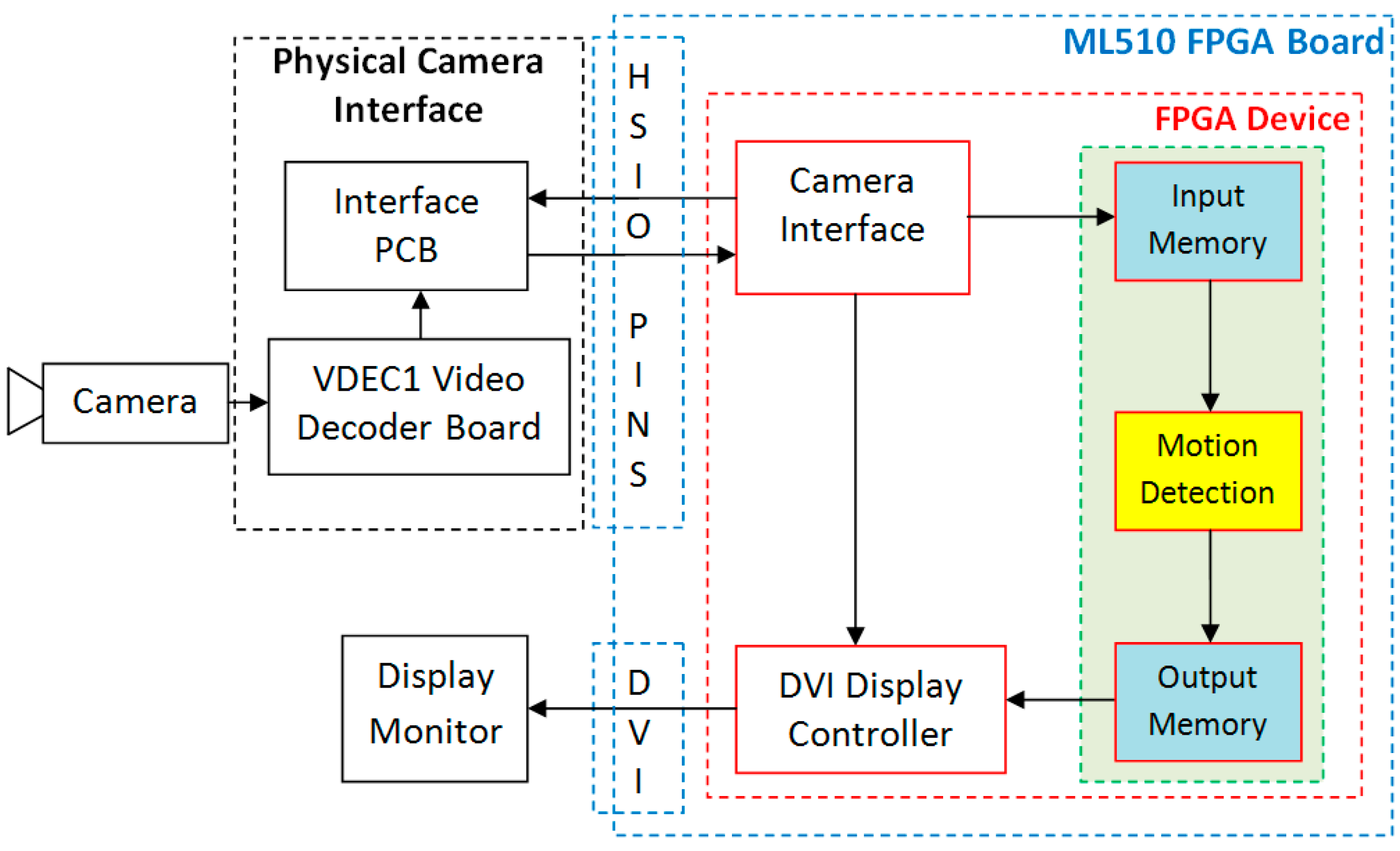
A simplified conceptual block diagram of the proposed and developed FPGA-based motion detection system is shown in Figure 5 to illustrate the data flow within the system. The main components of a complete FPGA-based standalone motion detection system are: analog Camera, VDEC1 Video Decoder Board for analog to digital video conversion, custom designed Interface PCB, Xilinx ML510 (Virtex-5 FX130T) FPGA platform for performing real-time motion detection, and a display device (Display Monitor).
Input video, captured by a Sony Analog Camera, is digitized by Digilent VDEC1 Video Decoder Board. The digital output signals from the video decoder board are transferred to FPGA platform using high speed I/O ports (HSIO PINS) available on Xilinx ML510 (Virtex-5 FX130T) FPGA Board using custom designed Interface PCB. The components inside dashed blue line are available on Xilinx ML510 (Virtex-5 FX130T) FPGA Board. These include FPGA Device (shown by dashed red line), High Speed Input Output Interface (HSIO PINS), and DVI Interface. The Camera Interface module uses the digital video signals available at the FPGA interface and extracts RGB data and generates Video Timing Signals. The DVI Display Controller is used to display the processed data on Display Monitor.
Data arrive from the Camera Interface module row by row. As motion detection scheme is based on the processing of 4 × 4 image blocks, therefore, streaming video processing cannot be used for clustering based motion detection scheme. For this reason, the four rows of image data are buffered in Input Memory before processing begins. The Motion Detection architecture takes its input from the Input Memory and processes the data. The output of Motion Detection module is stored in Output Memory for synchronization purpose before sending it for display. This is because the output data of Motion Detection module is for 4 × 4 pixel block while the DVI Display Controller takes the input data row by row. The processed image pixel data from Output Memory along with video timing signals is sent for display on Display Monitor through DVI Interface available on FPGA board. The three modules (Input Memory, Motion Detection, and Output Memory) within green dashed line form the clustering based motion detection architecture.
3.1. Motion Detection VLSI Architecture
A dedicated VLSI architecture has been proposed and implemented by us for the memory efficient motion detection algorithm is shown in Figure 6. This block level architecture is the same as that proposed earlier for the original clustering-based motion detection scheme except that it does not have FRNM MEM memory and its associated modules required to update FRNM MEM. However, the functionalities, and therefore the internal architectures for the individual blocks are different as compared to those in the architecture for the original clustering-based motion detection scheme [24]. There are two major advantages of the architecture being presented over the previously discussed architecture for the original clustering-based motion detection algorithm. Firstly, the proposed architecture has no frame number memory (FRNM MEM) component and therefore it requires much less parameter memory. Secondly, the associated logic modules necessary for updating frame number memory (FRNM MEM) are also eliminated, thereby, reducing the computational complexity. All the modules of the proposed architecture are explained in detail individually in the following sub-sections.
In this architecture, INPUT MEM module receives the incoming pixel data as input and buffers it in the memory. The output of INPUT MEM is fed to BLCENT COMPUTATION UNIT which computes the average centroid for 4 × 4 image block by taking pixel data from input memory (four clock cycles are required for reading 16 pixels from input memory buffer as four pixels are read in one clock cycle). Read address, write address, and write enable signals for input memory are generated by corresponding INPUT-MEM RADD-WRADD WEN module. MOTION COMPUTATION ENABLE UNIT generates the motion computation enable (MCEN) signal which is used as enable single for different modules of motion detection architecture.
Different control signals are generated by the COUNTERS & CONTROLLER MODULE. Each Centroid Memory location contains four Centroid values (corresponding to four clusters), which contain the background color and intensity related information. The read address and write address signals for CENT-MEM are generated by the corresponding CENT-MEM RADD-WRADD UNIT.
Minimum Centroid difference value is computed by the MINIMUM CENT DIFF COMPUTATION UNIT. It outputs MCD (minimum centroid difference value) and CINDX (Centroid Index). CINDX gives the cluster number corresponding to MCD (minimum centroid difference value). MCD is used to find a matching cluster. The MCD and BLCENT values are used by CENT-MEM WDATA COMPUTATION UNIT to compute the write data for Centroid Memory (CENT MEM). The CINDX value is used by CENT-MEM WEN UNIT for generating the write enable signal for CENT MEM. The MD FLAG takes MCD as input, compares it with a user defined threshold value, and the one-bit motion detection Flag signal is generated which is low if no motion is detected for current block and is high if current block is motion detected block. This motion information data of 4 × 4 pixel block is written to OUTPUT MEM and corresponding addresses for this memory are generated by OUTPUT-MEM RADD-WRADD WEN module. Finally, the motion detected data are read from this output buffer memory and sent to the display controller for display on the screen.
3.1.1. Input Buffer Memory
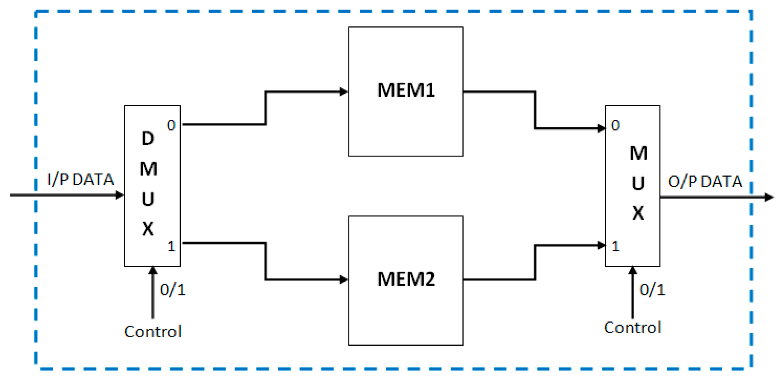
As mentioned in the algorithm section, the motion detection is performed for 4 × 4 pixel blocks. Therefore, it is not possible to process the incoming data directly. Four rows of input image pixel data must be available before processing begins. For this purpose, the input buffer memory module is used to buffer the four rows of input image data. To enable the real-time processing for this kind of requirements, the dual memory architecture (Figure 7) is most suitable. There are two memories (MEM1 and MEM2) in parallel. If the data are written in first memory, then the reading is performed from the second memory and vice-versa. Each of the memories is constructed by four block RAMs in the FPGA. Each block RAM is used to buffer one row of image pixel data. The width of each block RAM is 24 bits (eight bits for each Red, Green, and Blue color channels). In total, eight 36-Kb Block RAMs are needed for the complete Input Buffer Memory Architecture for processing PAL resolution color video.
A novel smart buffer based input memory architecture for block-level (4 × 4 pixels) memory efficient clustering based motion detection scheme that aims at reducing the Block RAM requirements for input memory has been proposed in this sub-section of the paper. The proposed architecture (Figure 8) uses three FIFOs (First-in first-out registers) and four 24-bit registers. The width of the FIFOs is 24 bits and length of the FIFOs is 719 locations. These three FIFOs are designed using the Block RAMs on FPGA. The complete architecture for the input buffer memory using Block RAMs is shown in Figure 9.
This proposed architecture requires only three 36-Kb Block RAMs instead of eight 36-Kb Block RAMs that are required by the earlier proposed architecture and also maintains the real-time processing. The processing can begin as soon as three rows of pixel data arrive in the FIFOs and the fourth row begins. At the start of the fourth row, this architecture provides access to the four pixel data corresponding to each of the four rows. The motion detection block starts working for every fourth row. The first-in first-out mechanism keeps only the data of the four rows necessary for processing and pushes out the unnecessary data. This mechanism is very effective for block based processing. It requires the number of FIFOs equal to the number of rows in the block minus one. The length of each FIFO is equal to the number of pixels in one row minus one. This new architecture saved five 36-Kb Block RAMs as compared to the dual memory architecture for PAL size color video processing.
3.1.2. Motion Computation Enable Unit
Based on the value of row counter RW4C (reset after every fourth row, i.e., counts from 00 to 11) and column counter CL4C (reset after every fourth column, i.e., counts from 00 to 11) the motion computation enable (MCEN) signal is generated and stored in REG1 (Figure 10). This one-bit MCEN signal is used for enabling the other blocks of motion detection system. It is set to “1” only if both RW4C and CL4C are “11”, which indicates that a 4 × 4 pixel block is available for processing.
3.1.3. Parameter Memory
Hardware architecture for memory efficient motion detection algorithm requires only one component of parameter memory (i.e., centroid memory) as compared to two components (i.e., centroid memory and frame number memory) required by the hardware architecture of original clustering based motion detection algorithm [24]. Centroid memory (CENT MEM) stores centroid values of four clusters for all image blocks. This memory contains four memory modules in parallel, each corresponding to one cluster. Each centroid memory module is eight-bit wide and is of size 25,920 locations. The four-centroid parameter memory modules are CM1, CM2, CM3, and CM4. Data are written to and read from all the four memories from same locations at a time. Therefore the read address (RDADDCM), write address (WDADDCM), and write enable signal (WRENCM) for all centroid memories are common. The complete centroid memory architecture is shown in Figure 11.
Centroid memory input write data (CMWD) and output read data (CMRD) are 32-bit wide each. For both input data and output data, the first set of eight bits (7 down to 0) is for the first cluster centroid value (CM1), the second set of eight bits (15 down to 8) is for the second cluster centroid value (CM2), the third set of eight bits (23 down to 16) is for the third cluster centroid value (CM3), and the last set of eight bits (31 down to 24) is for the fourth cluster centroid value (CM4). There are three such memories working in parallel each corresponding to Red, Green, and Blue color components.
3.1.4. Block Centroid Computation Module
Block Centroid Computation module (Figure 13) computes the average centroid of 4 × 4 pixel block. It receives four pixels at a time as inputs. Therefore, it takes four cycles in total to compute 4 × 4 pixel block average centroid. In the first cycle, the incoming four pixels are added by using three adders. The 10-bit sum output is “0” extended by two bits resulting in a 12-bit signal. It is directly stored in REG2 register using 4:1 multiplexer MX1 as CL4C is “00” in the first cycle. In the second and third cycles (for “01” and “10” values of CL4C), the sum of incoming four pixels is added with the stored sum in REG2 and the result is stored back in REG2. In the fourth cycle (for “11” value of CL4C), the last set of 4 pixels of present block is received. The sum of these four pixels is added with the previously stored sum in REG2, resulting in the sum of 16 pixels of the current block. This sum value of the current block is divided by 16 resulting in the current block Centroid (BLCENT). The division by 16 is performed by right shift operations. This value is stored in register REG1 with the help of 4:1 multiplexer MX2. The value of current block centroid is stored in REG1 only when both RW4C and CL4C are “11” (i.e., when complete 4 × 4 pixel block Centroid is computed) otherwise the value in REG1 remains 0. The output of REG1 (BLCENT) is used in further computations.
In order to deal with color video processing (in RGB color space), there are three such block Centroid computation modules in parallel, each computing the 4 × 4 pixel block centroid for each color channel R (first set of eight bits, i.e., 0 to 7 bits of incoming 24-bit pixel data), G (second set of eight bits, i.e., 8 to 15 bits of incoming 24-bit pixel data), and B (third set of eight bits, i.e., 16 to 24 bits of incoming 24-bit pixel data). The outputs of these three blocks are three color channels’ block Centroid values BLCENTR, BLCENTG, and BLCENTB (each of eight-bit). These are used for further processing.
3.1.5. Minimum Centroid Difference Computation Module
The function of Minimum Centroid Difference Computation (Figure 14) block is to find the minimum centroid difference and corresponding centroid index value. The current block centroid value for each color channel is subtracted from its corresponding centroid values of the four clusters (read from Centroid memories CENT MEM). The minimum centroid difference for a particular cluster is computed by using the sum of absolute differences for the three color channels. There are four sums of absolute difference values corresponding to each one of the four clusters.
The first two differences of the first two clusters (DIFF1 and DIFF2) are compared using a comparator and the minimum difference among the two (MDIFF1) is selected using a multiplexer (MX1). The corresponding index value (INDX1) is also computed using a multiplexer (MX2). This index value gives the cluster number having the minimum difference value. Similarly, the remaining two differences of the last two clusters (DIFF3 and DIFF4) are compared using a comparator and the minimum difference among the two (MDIFF2) is selected using a multiplexer (MX3). The corresponding index value (INDX2) is also computed using a multiplexer (MX4). Finally, using a comparator and a multiplexer (MX5), the minimum centroid difference (MCD) is computed. The centroid index (CINDX) is also computed using values INDX1 and INDX2 and a multiplexer (MX6). This CINDX gives the cluster number to which minimum centroid difference (MCD) value belongs. The MCD and CINDX are used in further computations.
3.1.6. Initialization-Update-Replace Module
This module is the heart of motion detection architecture. The proposed architecture for the Initialization-Update-Replace module of memory efficient motion detection scheme is shown in Figure 15. This architecture is for one color component and the complete architecture for color video processing consists of three such blocks in parallel (one for each color component R, G, and B). There are two main tasks performed by this architecture. Firstly, it computes data to be written in centroid parameter memories (CENT MEM) during cluster group initialization, cluster updating, and cluster replacement processes. Secondly, it rearranges data in the order of newest value, second newest value, second oldest value, and oldest value in CM1, CM2, CM3, and CM4, respectively, before sending the data for writing to centroid memories. Data are written to the memories only when MCEN is high.
For initial four frames, the initialization process takes place. During initialization, the centroid parameter memory is initialized with incoming frame block centroid values. The architecture for cluster group initialization is shown within blue dashed lines in Figure 15. This architecture block generates 32-bit data for initialization of four centroid memories CM1, CM2, CM3, and CM4 (8-bit for each memory) according to the proposed algorithmic procedure discussed in algorithmic section. The data selection is done based on frame number value (FRNUM) using multiplexer.
In the first frame, the block centroid (BLCENT) is written to CM4 memory and therefore the 32-bit output data are “BLCENT-000000000000000000000000”. In the second frame, the block centroid (BLCENT) is written to CM3 memory and therefore the 32-bit output data are “CMRD31:24-BLCENT-0000000000000000”. As the write enable is common for all the four memories, therefore, the data read or write operation for all memories is performed at the same time. For this reason, the read data (CMRD) of centroid memories are also sent back for writing into corresponding memories if it is to be retained at same location. The common write enable, read address, and write address signals are used for all four centroid memories to simplify the logic blocks for generating these signals. In the third frame, the block centroid (BLCENT) is written to CM2 memory and therefore the 32-bit output data are “CMRD31:16-BLCENT-00000000”. In the fourth frame, the block centroid (BLCENT) is written to CM1 memory and therefore the 32-bit output data are “CMRD31:8-BLCENT”. At the end of the fourth frame, all four centroid memories are initialized and contain data in the order of newest (CM1) to oldest (CM4) centroid values.
For all subsequent frames, there are two possibilities. Existing data are either updated or replaced depending upon the value of MCD. If MCD value is greater than the user defined threshold, then cluster replace is performed. In this case, the oldest cluster centroid value is replaced by current block centroid value. For this purpose, CM4 centroid memory value (which is the oldest centroid value) is replaced by current block centroid value. As the replaced value in CM4 is the newest value, therefore, the other memory values are rearranged in order of newest value, second newest value, second oldest value, and oldest value in CM1, CM2, CM3, and CM4 respectively. This is done by shifting the centroid values of CM1, CM2, and CM3 into CM2, CM3, and CM4, respectively and moving the current block centroid value held in CM4 into CM1. Therefore, the generated 32-bit data are“CMRD23:0-BLCENT”. The architecture block for cluster replace is shown within red dashed line in Figure 15.
If MCD value is less than the user defined threshold then cluster updating process is performed. During cluster update process, first the centroid value corresponding to minimum difference value is selected based on the centroid index (CINDX) value using a 4:1 multiplexer MX1 and then added with the current block centroid BLCENT. The result is divided by two using a right shift to get the average value (AVG). This average value updates the centroid value in centroid memory corresponding to CINDX using multiplexer MX2. After this, the values of all four centroid memories are rearranged in the order of newest value, second newest value, second oldest value, and oldest value in CM1, CM2, CM3, and CM4, respectively according to the algorithmic rules. This is achieved by shifting and concatenation operations. The 32-bit data generated for centroid memories are “CMRD31:8-AVG” if CINDX is “00”, “CMRD31:16-CMRD7:0-AVG” if CINDX is “01”, “CMRD31:24-CMRD15:0-AVG” if CINDX is “10”, or “CMRD23:0-AVG” if CINDX is “11”. For all the four cases of cluster update, at the end, centroid values in the four centroid memories CM1, CM2, CM3, and CM4 are in the order of newest value, second newest value, second oldest value, and oldest value, respectively. The architecture block for cluster updating is shown within green dashed line in Figure 15.
The selection of output data for REPLACE MODULE, UPDATE MODULE, and INITIALIZATION MODULE is done using 2:1 multiplexer MX3 and 4:1 multiplexer MX4. The output data are written to output register REG1 only if MCEN is high, otherwise “0” value is stored in REG1. The output of REG1 (CMWD) is sent to centroid parameter memory for writing.
3.1.7. Motion Detection Flag Computation
This module classifies the current 4 × 4 pixel block as motion block or non-motion block. The architecture for this block is shown in Figure 16. This motion detection information is indicated by motion detection flag (MDF) signal value. MDF value of zero indicates no motion detection for the current block, and MDF value of one indicates motion detection for the current block. For the initial four frames, the initialization process takes place, and therefore MDF remains zero for the initial four frames. As motion detection is performed for 4 × 4 pixel blocks, therefore, the motion detection works only if MCEN (motion computation enable) is high. This implies that motion detection process works only if MCEN is high and frame number (FRNUM) is greater than four. If both these conditions are satisfied, then the minimum centroid difference (MCD) is compared with a user defined threshold. The one-bit Motion Detection Flag (MDF) signal is set low (“0”) if the difference is less than the threshold (i.e., current block matches with background model and therefore, no motion is detected) and high (“1”) if the difference is greater than the threshold (i.e., current block is motion detected block).
3.1.8. Output Buffer Memory
While the motion detection output (i.e., motion detection flag (MDF)) represents the motion information of a 4 × 4 pixel block, the display controller requires the processed data in row by row sequence for sending it to the display device. For this reason, to properly synchronize the motion detection output with display controller inputs, a buffer memory is used at the output end of the motion detection architecture. The motion detection flag (MDF) is stored in this output buffer memory (OUTPUT MEM) (Figure 17). Finally, the motion detected data stored in this output buffer memory is read row by row and sent to the display controller for display on the screen.
To enable real-time processing and displaying, two output memory modules OP-M1 and OP-M2 are used in parallel. Each one-bit motion detection flag (MDF) output represents motion information for one 4 × 4 pixel block. Therefore, to store the motion information of four rows we need 180 (i.e., 4 × 720/16) memory locations. The size of output memory is 180 locations, each one-bit wide. When processed data are being written to one memory, data from the second memory are read for sending to the display controller and vice versa.
Read and write addresses (Figure 18) for the two output memories are generated using conditional counters (i.e., counter increments only when a particular condition is satisfied). Both the addresses are eight-bit wide. The read address in incremented only when CL4C (Column 4 Count) is 11 (i.e., counts four pixels of row). The write address is incremented only when MCEN (Motion Computation Enable) is high. These addresses are reset when their values reach 180. The write enable signals for these two output memories are set true only when MCEN is high. The write enable signal for OP-M1 (WRENOM1) and write enable signal for OP-M2 (WRENOM2) are complements of each other to ensure that data are written into only one output memory at a time: either in OP-M1 or in OP-M2 (Figure 19).
3.1.9. Control Signals
In this subsection, we discuss the generation of some of the most important control signals required for proper synchronization and functioning of complete motion detection system. The logic blocks for generating these signals are shown in Figure 20. The first important signal is the SWITCH signal. This signal changes after every four rows. At the end of the fourth row, the RW4C value changes to 00 and the SWITCH signal value is complemented. Then, for the next four rows, the value remains the same. This signal is generated with the help of a comparator, register, multiplexer, and not gate. Second signal is the frame number signal (FRNUM). It is a three-bit signal and distinguishes between cluster group initialization process and subsequent processes. It is used in the cluster initialization architecture to select a particular cluster to be initialized. It is generated with the help of a comparator, adder, multiplexer, and register. The clock for the frame number generation architecture is vertical blanking signal (VBLK) which indicates end of the video frame. The frame number value is incremented by 1 when one frame completes. The frame number counter counts up to five, and then, for all subsequent frames, its value remains five.
The other two important signals are CL4C and RW4C. These two signals are used for processing 4 × 4 pixel blocks. The CL4C is used to count four columns of pixel data in a row. This signal has four values and counts from 00 to 11. Its value becomes 00 after every fourth column of pixel data in a row and is reset to 00 at the end of every row of image pixel data. CL4C signal value is incremented every pixel clock cycle. The RW4C is used to count four rows of image pixel data. It also counts from 00 to 11. This counter is incremented at the end of each row of the image pixel data. The clock used for this counter is horizontal blanking signal (HBLK) which indicates the end of one row of data in a video frame. The RW4C becomes 00 at the end of every fourth row of image pixel data. SWITCH, CL4C, and RW4C signals are reset before the start of every new frame of incoming video.
4. Results and Discussions
4.1. Synthesis Results
All of the above-mentioned modules of the proposed and designed memory efficient motion detection VLSI/hardware architecture were coded in VHDL and simulated using ModelSim. A top level design module was created which invoked the memory efficient motion detection architecture, camera interface, and display controller module. A User Constraint File (UCF) was created to map the input/output ports of the design on actual pins of the FPGA. This top level design was synthesized using Xilinx ISE (Version 12.1) tool chain. The resulting configuration (.bit) file was stored in the Flash Memory to enable automatic configuration of the FPGA at power-on. Thus, a complete standalone prototype system for real-time motion detection was developed, as shown in Figure 21. The components of the system are Xilinx ML510 (Virtex-5 FX130T) FPGA platform, Sony EVI D-70P Camera, and display monitor.
Table 1 shows the comparison of FPGA resources (post-place and route results) utilized by the hardware architecture of original clustering based motion detection scheme [24] and by the proposed and implemented memory efficient motion detection hardware architecture. It is clear from the table that the memory efficient architecture utilizes 41% less on-chip memory (Block RAMs) and 24% less FPGA Slices. Therefore, this architecture is FPGA resource and area efficient.
Table 2 presents FPGA resources utilized (post-place and route results) by the complete implementation of motion detection system using memory efficient hardware architecture. The maximum operating frequency is 154.55 MHz and maximum possible frame rate for PAL (720 × 576) size color video is 372 frames per second. Synthesis results also reveal that enough FPGA resources are left for implementing other complex computer vision algorithms required by automated video surveillance system on the same FPGA platform, as the memory efficient motion detection system proposed, designed, and implemented by us utilizes only around 34% Block RAMs and 3% FPGA slices. The implemented system yields good results and works in real-time.
Performance of the proposed, designed, and implemented memory efficient motion detection hardware architecture is compared with some recently published motion detection hardware implementations using different algorithms. The performance comparison is shown in Table 3.
VLSI implementation of original clustering based motion detection scheme has been presented in [24]. The motion detection/segmentation architectures presented by Genovese and Napoli [27] and Genovese et al. [28] were designed for OpenCV GMM algorithm and were implemented on Virtex5 (xc5vlx50-2ff1153) FPGA. The motion segmentation circuit proposed by Genovese and Napoli in [25] has been implemented on both Virtex6 (xc6vlx75t-3ff784) and Virtex5 (xc5vlx50-2ff1153) FPGAs and is an improved version of the work presented by them in [27] and [28]. Jiang et al. [29] and Kristensen et al. [30] have presented the design of a digital surveillance system running in real-time on an embedded platform. The motion detection/segmentation unit of the circuit proposed by these researchers is able to run at 83 MHz on Virtex-IIPro (xc2pro30-5ff1152) FPGA. For accurate performance comparison with the work reported in literature [24,25] and [27,28,29,30], the proposed memory efficient architecture has also been synthesized (including place and route) for Virtex6 (xc6vls75t), Virtex5 (xc5vls50), and Virtex-IIPro (xc2pro30) FPGA devices using Xilinx ISE tool chain.
The memory efficient motion detection VLSI/hardware architecture proposed in this paper outperforms existing implementations in terms of processing speed while occupying less FPGA resources. Although the FPGA resources utilized by the memory efficient architecture proposed and implemented in this paper are lesser than the existing implementations in the literature [24,26,27,28,29,30], nevertheless, an apple to apple comparison of FPGA resource utilization does not make proper sense as the number of background models considered and the video formats and sizes considered in these implementations are different than in our implementation. For this reason, one to one FPGA resource utilization comparisons are not tabulated here.
The system architecture for motion detection, proposed, designed, and implemented by us is adaptable and scalable for different video sizes. It is capable of processing high definition (HD) videos (1920 × 1080 resolution color videos) in real-time at the frame rate of 74 frames per second.
4.2. Motion Detection Results
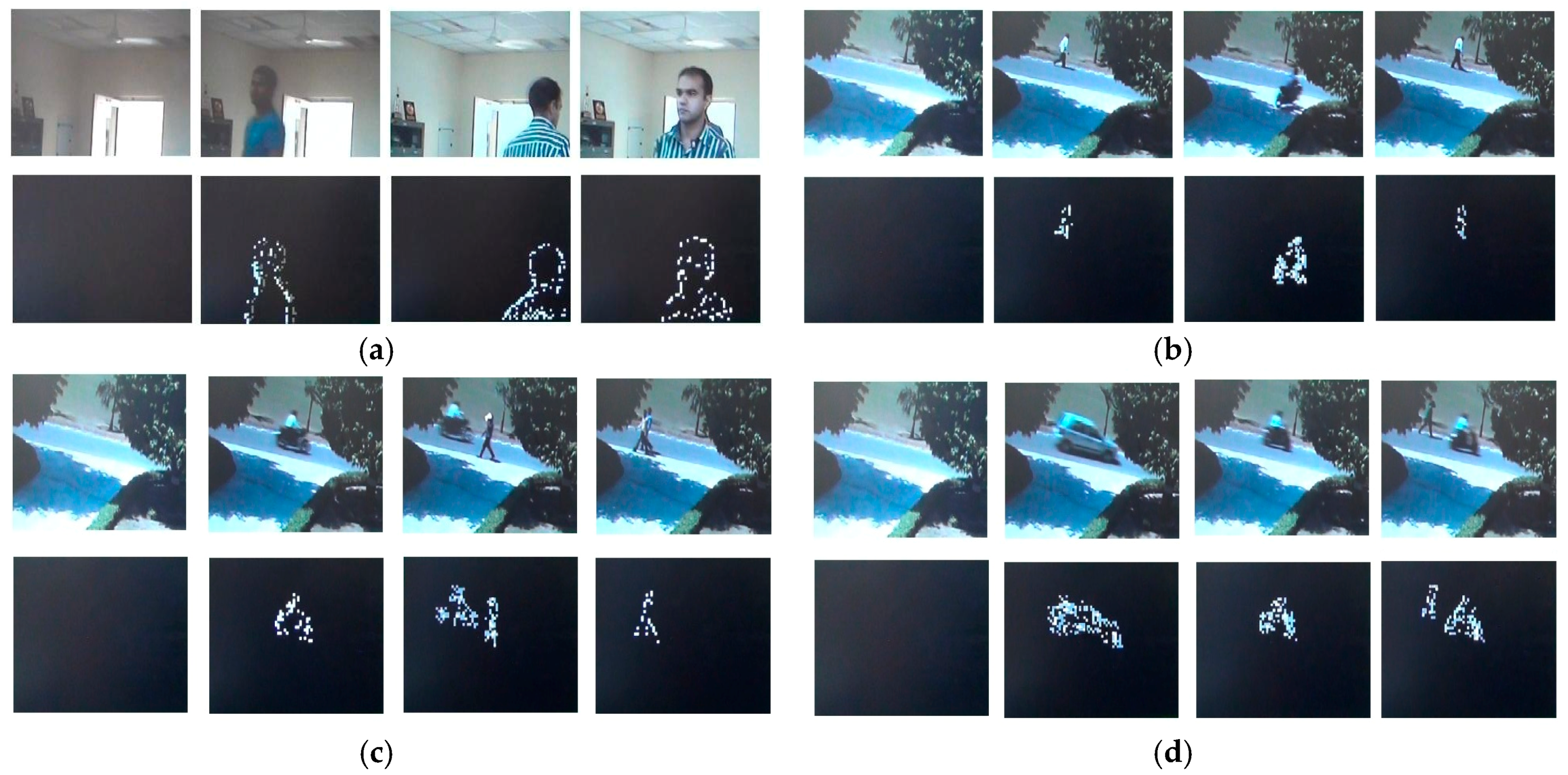
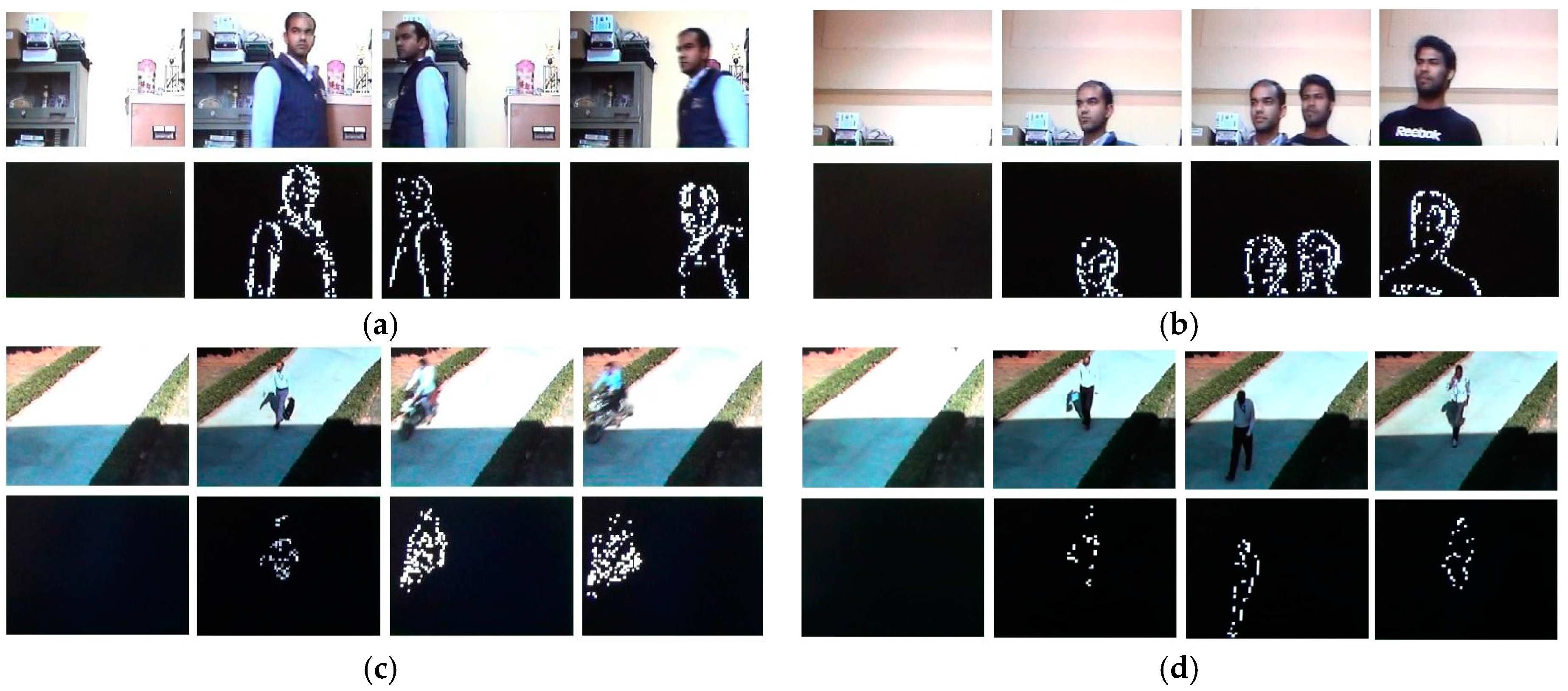
For robust and real-time testing of the implemented system, the system was run for different real-world scenarios (both indoor and outdoor) under different lightening conditions. The real-world scenarios are broadly classified into two categories, i.e., static background situations and pseudo-stationary background situations. Figure 22 shows examples of real-world situations of static background scenarios captured by the camera. In all cases in Figure 22, the background is static and moving objects are present in the scene. Motion detected by our implementation in different frames is shown just below the respective images. It can be clearly seen that only moving objects have been detected by the implemented motion detection system.
Scenarios of pseudo-stationary background with moving foreground objects are considered in Figure 23. In the first case (Figure 23a), despite the moving fan in the background, only moving objects in the foreground are detected. In the second case (Figure 23b–d), the movements of leaves of trees in the background (irrelevant motion) have been eliminated and only relevant motion is detected.
The test scenarios (Figure 22 and Figure 23) for both indoor and outdoor cases are considered under varying lighting conditions. Results of the tests show that the system is robust enough to detect only the relevant motion in a live video scene and eliminates the continuous unwanted movements in the background itself. All the above color frames are of PAL (720 × 576) and were taken at a frame rate of 25 fps. These frames and their results are extracted from live video streams produced by the implemented system.
If a motion threshold is not crossed in a video frame, the frame is rejected at this stage and if a motion threshold is crossed in a video frame, the frame is selected for further processing. This filtering of frames of interest reduces the communication and processing overheads of an automated video surveillance system for remote video surveillance scenarios.
5. Conclusions
In this paper, we have proposed and described the design and implementation of a standalone system for motion detection in real-time. To address the issue of large on-chip memory requirement of original clustering based motion detection scheme, a new memory efficient motion detection algorithm has been proposed and the corresponding dedicated hardware architecture has been designed and implemented on FPGA. The new memory efficient architecture uses approximately 41% less FPGA Block RAMs (on-chip memory) as compared to proposed and implemented architecture for original clustering based motion detection scheme. The complete system, including camera interface, memory efficient motion detection architecture, and display interface has been implemented on Xilinx ML510 (Virtex-5 FX130T) FPGA Board. As demonstrated on video sequences, the new memory efficient system robustly and automatically detects motion in real-world scenarios (both for the static backgrounds and the pseudo-stationary backgrounds) in real-time for standard PAL (720 × 576) size color video. The implemented system can be effectively used as a standalone system for motion detection and filtering of frames of interest in a remote video surveillance scenario for reducing communication requirements and processing overheads.
Acknowledgments
The financial support of Department of Electronics & Information Technology (DeitY)/Ministry of Communications and Information Technology (MCIT), and the Government of India is gratefully acknowledged.
Author Contributions
Sanjay Singh, Atanendu Sekhar Mandal, Chandra Shekhar, and Anil Vohra conceived the design. Sanjay Singh implemented the design, analyzed the results, and wrote the paper.
Conflicts of Interest
The authors declare no conflict of interest. The founding sponsors had no role in the design of the study; in the collection, analyses, or interpretation of data; in the writing of the manuscript, and in the decision to publish the results.
References
- Radke, R.J.; Andra, S.; Kofahi, O.A.; Roysam, B. Image Change Detection Algorithms: A Systematic Survey. IEEE Trans. Image Process. 2005, 14, 294–307. [Google Scholar] [CrossRef] [PubMed]
- Rosin, P.L. Thresholding for Change Detection. In Proceedings of the Sixth International Conference on Computer Vision, Bombay, India, 4–7 January 1998; pp. 274–279. [Google Scholar]
- Rosin, P.L.; Ioannidis, E. Evaluation of Global Image Thresholding for Change Detection. Pattern Recognit. Lett. 2003, 24, 2345–2356. [Google Scholar] [CrossRef]
- Smits, P.C.; Annoni, A. Toward Specification-Driven Change Detection. IEEE Trans. Geosci. Remote Sens. 2000, 38, 1484–1488. [Google Scholar] [CrossRef]
- Bruzzone, L.; Prieto, D.F. Automatic Analysis of the Difference Image for Unsupervised Change Detection. IEEE Trans. Geosci. Remote Sens. 2000, 38, 1171–1182. [Google Scholar] [CrossRef]
- Colwell, J.E.; Weber, F.P. Forest Change Detection. In Proceedings of the 15th International Symposium on Remote Sensing of the Environment, Ann Arbor, MI, USA, 11–15 May 1981; pp. 839–852. [Google Scholar]
- Malila, W.A. Change Vector Analysis: An Approach for Detecting Forest Changes with Landsat. In Proceedings of the Symposium on Machine Processing of Remotely Sensed Data, West Lafayette, IN, USA, 3–6 June 1980; pp. 326–336. [Google Scholar]
- Singh, A. Review Article: Digital Change Detection Techniques using Remotely-Sensed Data. Int. J. Remote Sens. 1989, 10, 989–1003. [Google Scholar] [CrossRef]
- Stefano, L.D.; Mattoccia, S.; Mola, M. A Change-Detection Algorithm Based on Structure and Color. In Proceedings of the IEEE Conference on Advanced Video and Signal-Based Surveillance, Miami, FL, USA, 22 July 2003; pp. 252–259. [Google Scholar]
- Hsu, Y.Z.; Nagel, H.H.; Rekers, G. New Likelihood Test Methods for Change Detection in Image Sequences. Comput. Vis. Gr. Image Process. 1984, 26, 73–106. [Google Scholar] [CrossRef]
- Skifstad, K.; Jain, R. Illumination Independent Change Detection for Real World Image Sequences. Comput. Vis. Gr. Image Process. 1989, 46, 387–399. [Google Scholar] [CrossRef]
- Elfishawy, A.S.; Kesler, S.B.; Abutaleb, A.S. Adaptive Algorithms for Change Detection in Image Sequence. Signal Process. 1991, 23, 179–191. [Google Scholar] [CrossRef]
- Jain, Z.S.; Chau, Y.A. Optimum Multisensor Data Fusion for Image Change Detection. IEEE Trans. Syst. Man Cybern. 1995, 25, 1340–1347. [Google Scholar] [CrossRef]
- Toyama, K.; Krumm, J.; Brumitt, B.; Meyers, B. Wallflower: Principles and Practice of Background Maintenance. In Proceedings of the Seventh International Conference on Computer Vision, Kerkyra, Greece, 20–27 September 1999; pp. 255–261. [Google Scholar]
- Clifton, C. Change Detection in Overhead Imagery using Neural Networks. Appl. Intell. 2003, 18, 215–234. [Google Scholar] [CrossRef]
- Durucan, E.; Ebrahimi, T. Change Detection and Background Extraction by Linear Algebra. In Proceedings of the IEEE 2001 Custom Integrated Circuits Conference, San Diego, CA, USA, 6–9 May 2001; Volume 89, pp. 1368–1381. [Google Scholar]
- Li, L.; Leung, M.K.H. Integrating Intensity and Texture Differences for Robust Change Detection. IEEE Trans. Image Process. 2002, 11, 105–112. [Google Scholar] [PubMed]
- Liu, S.C.; Fu, C.W.; Chang, S. Statistical Change Detection with Moments under Time-Varying Illumination. IEEE Trans. Image Process. 1998, 7, 1258–1268. [Google Scholar] [PubMed]
- Cavallaro, A.; Ebrahimi, T. Video Object Extraction based on Adaptive Background and Statistical Change Detection. In Proceedings of the SPIE Visual Communications and Image Processing, San Jose, CA, USA, 20 January 2001; pp. 465–475. [Google Scholar]
- Huwer, S.; Niemann, H. Adaptive Change Detection for Real-Time Surveillance Applications. In Proceedings of the Third IEEE International Workshop on Visual Surveillance, Dublin, Ireland, 1 July 2000; pp. 37–46. [Google Scholar]
- Stauffer, C.; Grimson, W.E.L. Learning Patterns of Activity using Real-Time Tracking. IEEE Trans. Pattern Anal. Mach. Intell. 2000, 22, 747–757. [Google Scholar] [CrossRef]
- Butler, D.E.; Bove, V.M.; Sridharan, S. Real-Time Adaptive Foreground/Background Segmentation. EURASIP J. Appl. Signal Process. 2005, 2005, 2292–2304. [Google Scholar] [CrossRef]
- Chutani, E.R.; Chaudhury, S. Video Trans-Coding in Smart Camera for Ubiquitous Multimedia Environment. In Proceedings of the International Symposium on Ubiquitous Multimedia Computing, Hobart, Australia, 13–15 October 2008; pp. 185–189. [Google Scholar]
- Singh, S.; Shekhar, C.; Vohra, A. FPGA-based Real-time Motion Detection for Automated Video Surveillance Systems. Electronics 2016, 5, 10. [Google Scholar] [CrossRef]
- Genovese, M.; Napoli, E. ASIC and FPGA Implementation of the Gaussian Mixture Model Algorithm for Real-time Segmentation of High Definition Video. IEEE Trans. Very Larg. Scale Integr. 2014, 22, 537–547. [Google Scholar] [CrossRef]
- Rodriguez-Gomez, R.; Fernandez-Sanchez, E.J.; Diaz, J.; Ros, E. FPGA Implementation for Real-Time Background Subtraction Based on Horprasert Model. Sensors 2012, 12, 585–611. [Google Scholar] [CrossRef] [PubMed]
- Genovese, M.; Napoli, E. FPGA-Based Architecture for Real Time Segmentation and Denoising of HD Video. J. Real Time Image Process. 2013, 8, 389–401. [Google Scholar] [CrossRef]
- Genovese, M.; Napoli, E.; Petra, N. OpenCV Compatible Real Time Processor for Background Foreground Identification. In Proceedings of the International Conference on Microelectronics, Cairo, Egypt, 19–22 December 2010; pp. 467–470. [Google Scholar]
- Jiang, H.; Ardö, H.; Öwall, V. A Hardware Architecture for Real-time Video Segmentation Utilizing Memory Reduction Techniques. IEEE Trans. Circuits Syst. Video Technol. 2009, 19, 226–236. [Google Scholar] [CrossRef]
- Kristensen, F.; Hedberg, H.; Jiang, H.; Nilsson, P.; Öwall, V. An Embedded Real-Time Surveillance System: Implementation and Evaluation. J. Signal Process. Syst. 2008, 52, 75–94. [Google Scholar] [CrossRef]
Figure 1.
(a) Structure of parameter memory for storing centroid values of four clusters; and (b) cluster group initialization process.
Figure 1.
(a) Structure of parameter memory for storing centroid values of four clusters; and (b) cluster group initialization process.

Figure 2.
Cluster updating process: (a) first case; (b) second case; (c) third case; (d) fourth case.
Figure 2.
Cluster updating process: (a) first case; (b) second case; (c) third case; (d) fourth case.

Figure 3.
Cluster replacement process.
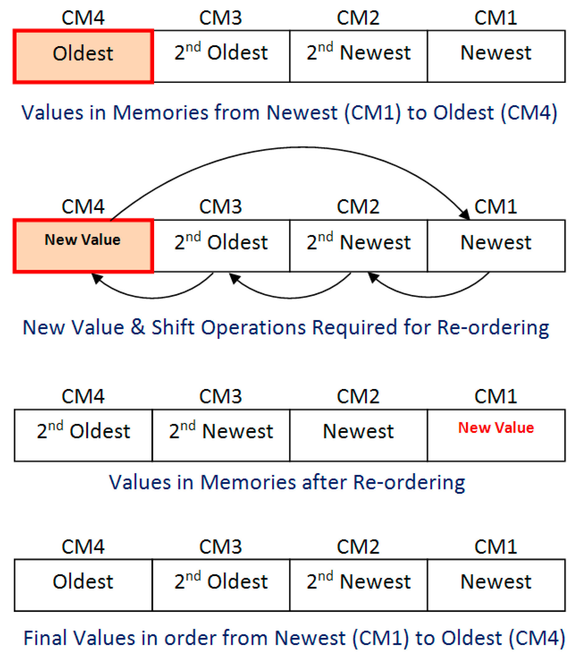
Figure 4.
Comparison of results of the proposed memory efficient motion detection algorithm with the original clustering based motion detection scheme for: (a) indoor scenario; and (b) outdoor scenario.
Figure 4.
Comparison of results of the proposed memory efficient motion detection algorithm with the original clustering based motion detection scheme for: (a) indoor scenario; and (b) outdoor scenario.
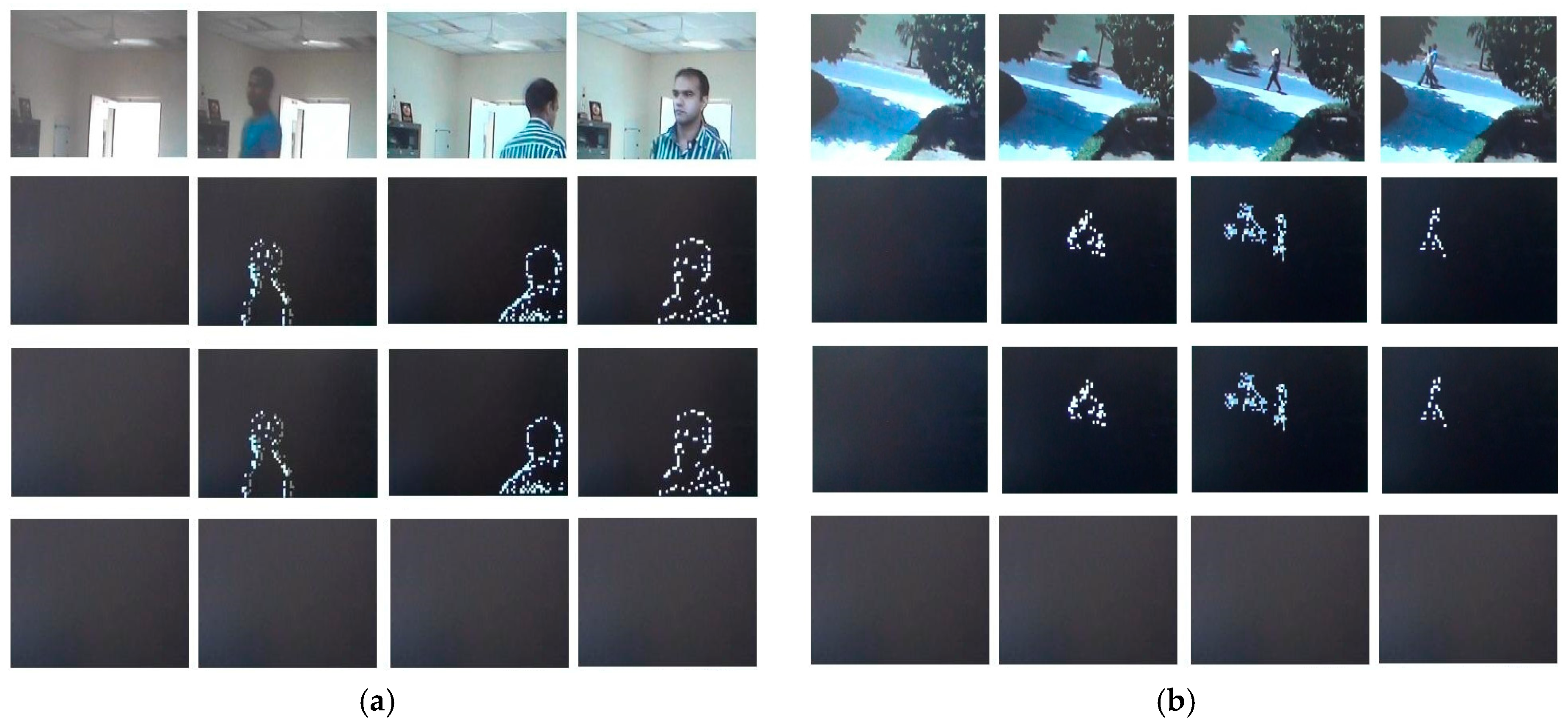
Figure 5.
Dataflow diagram of the proposed and developed motion detection system.

Figure 6.
Proposed VLSI architecture for the memory efficient motion detection algorithm.
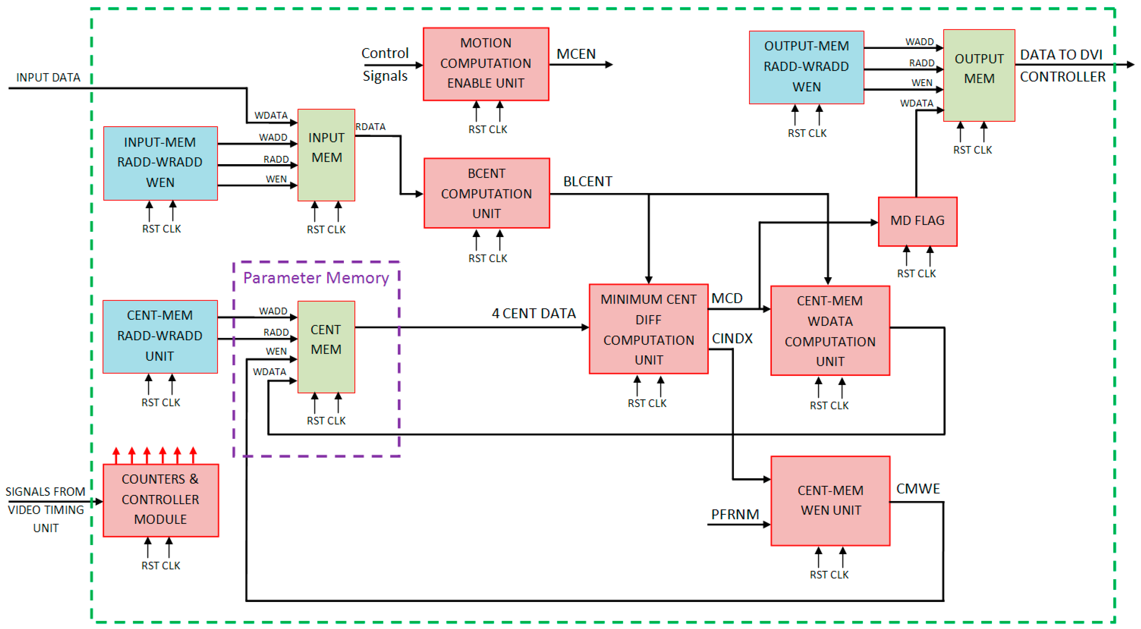
Figure 7.
VLSI architecture for input buffer memory.

Figure 8.
Proposed smart buffer based input buffer memory architecture.
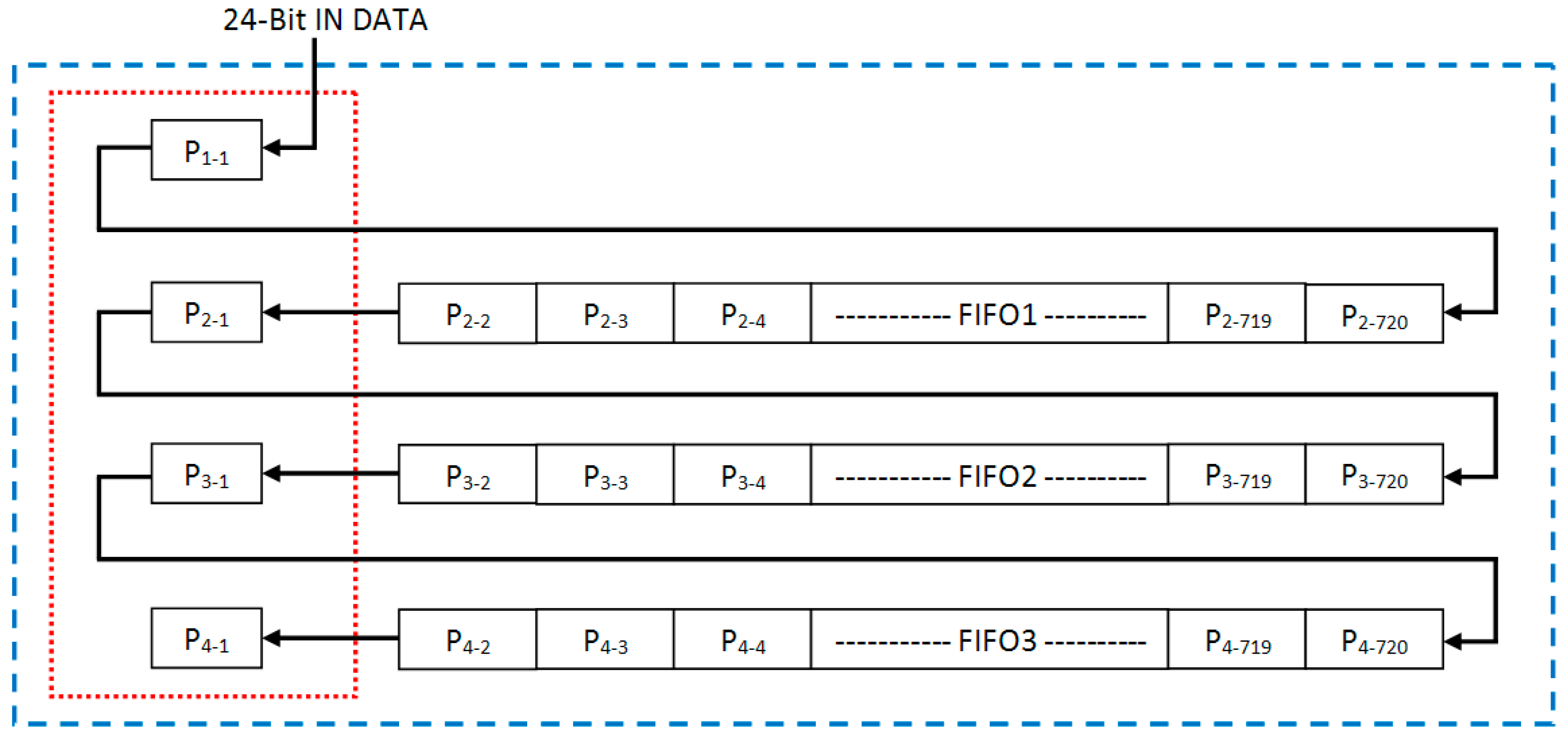
Figure 9.
Detailed implementation of input buffer memory architecture using block RAMs and registers.
Figure 9.
Detailed implementation of input buffer memory architecture using block RAMs and registers.
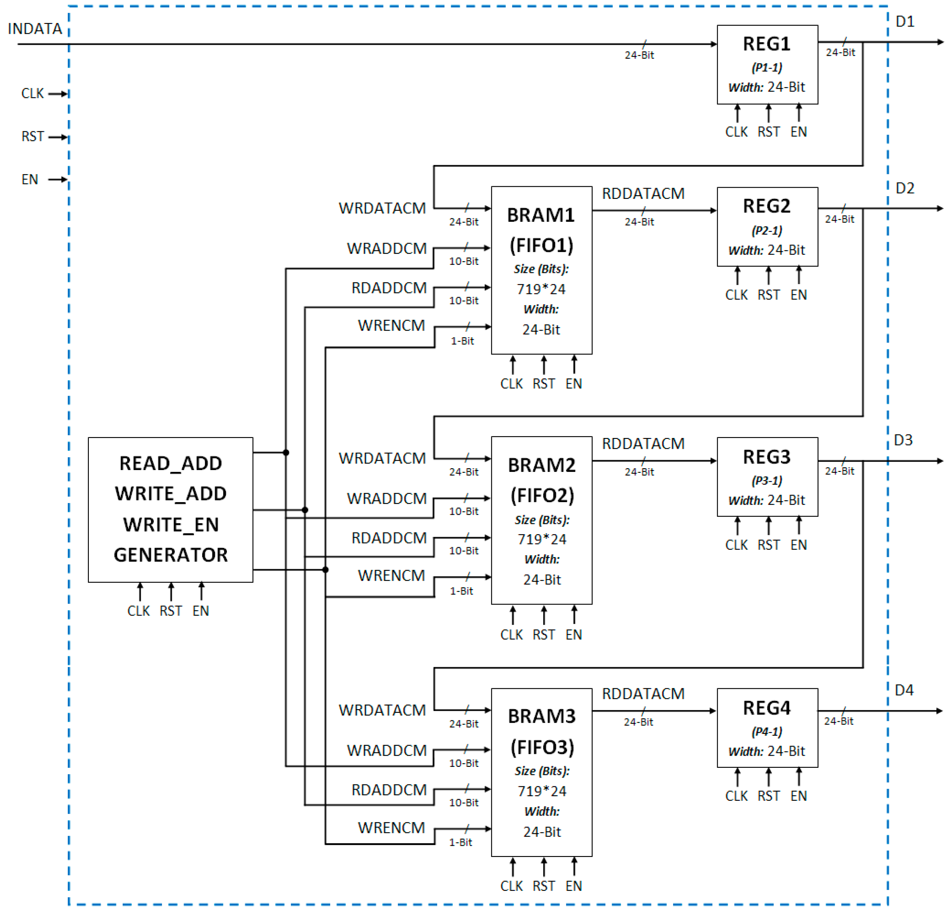
Figure 10.
VLSI architecture of motion computation enable signal generation unit.

Figure 11.
Centroid memory architecture.
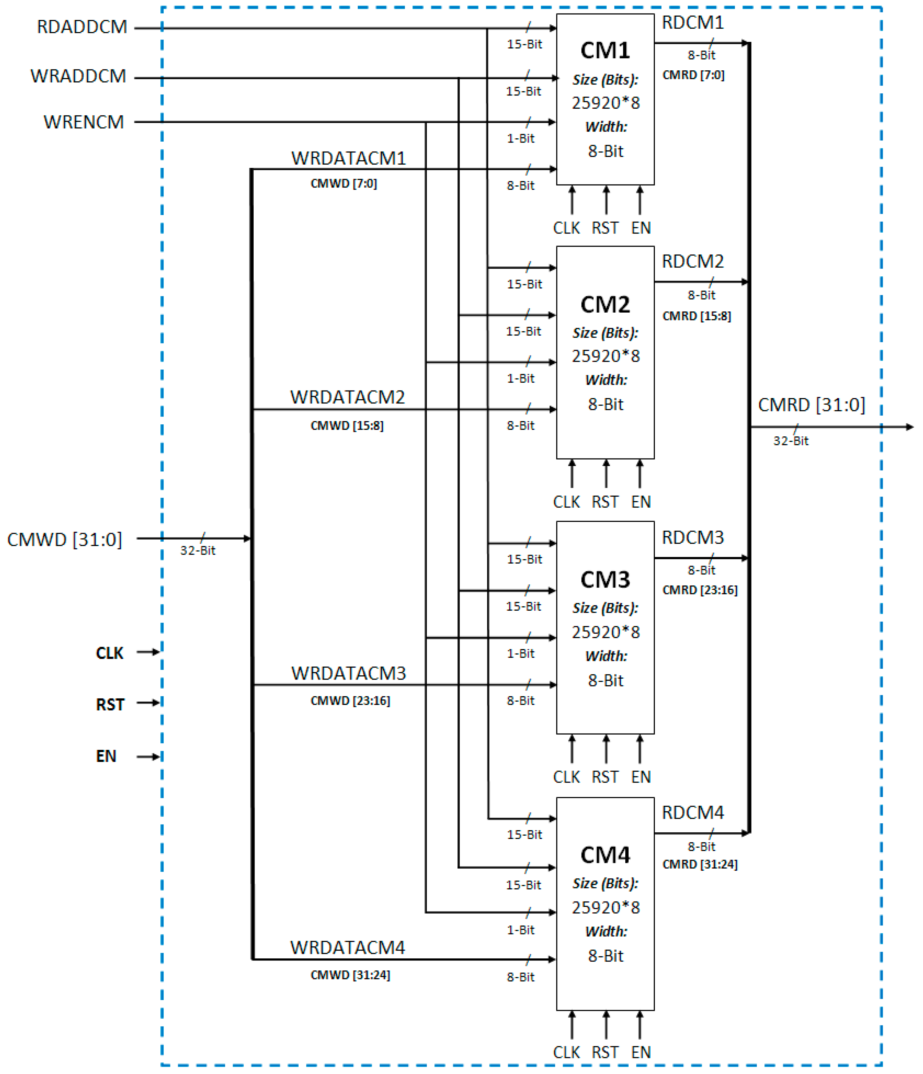
Figure 12.
Logic for generating: (a) write enable signal; (b) addresses for centroid memory.

Figure 13.
Proposed VLSI architecture for block centroid computation module.

Figure 14.
Proposed VLSI architecture for minimum centroid difference computation module.
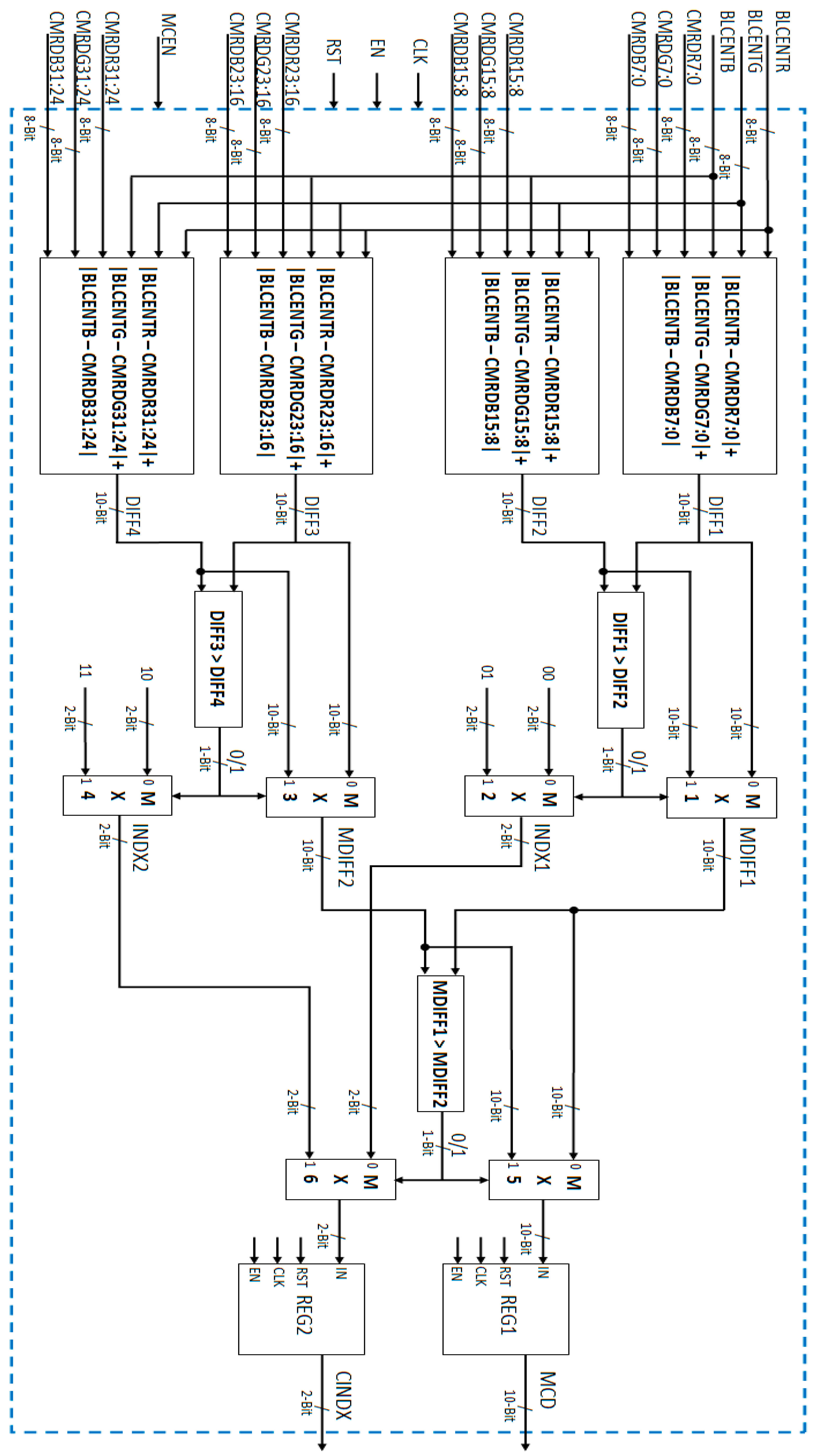
Figure 15.
Proposed VLSI architecture for cluster initialization, updating, and replacement.
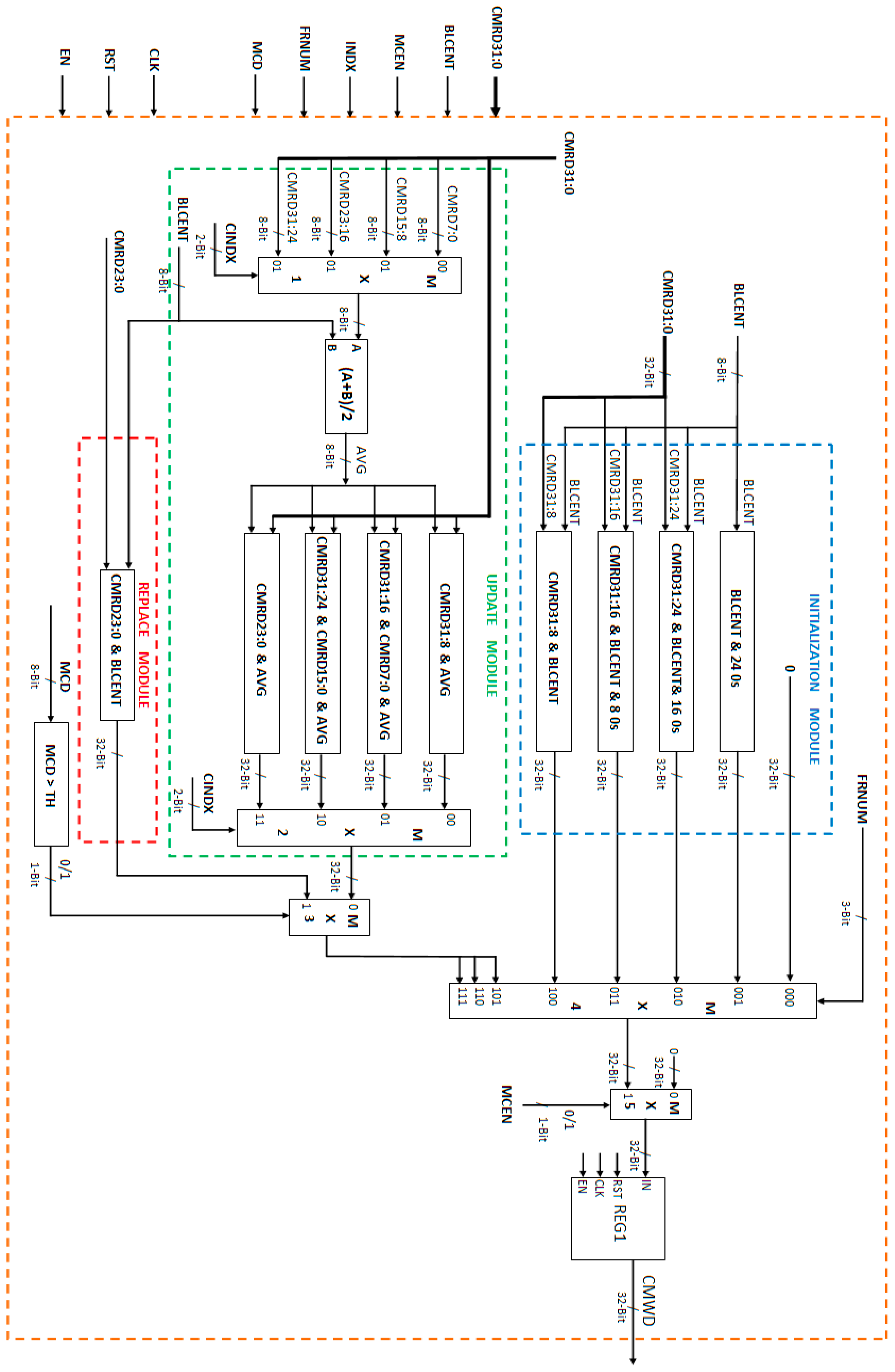
Figure 16.
Architecture of motion detection flag computation module.
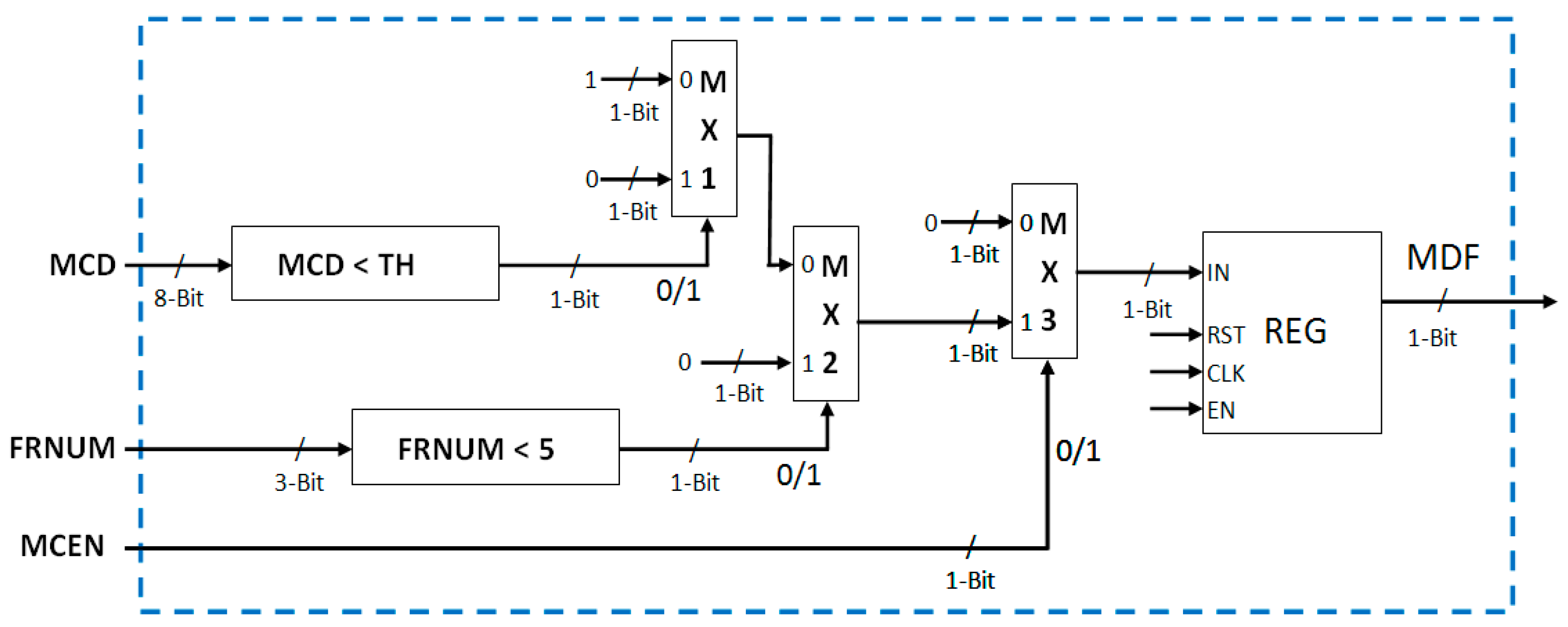
Figure 17.
Proposed output buffer memory architecture.

Figure 18.
Write address and read address generation logic of output memories.
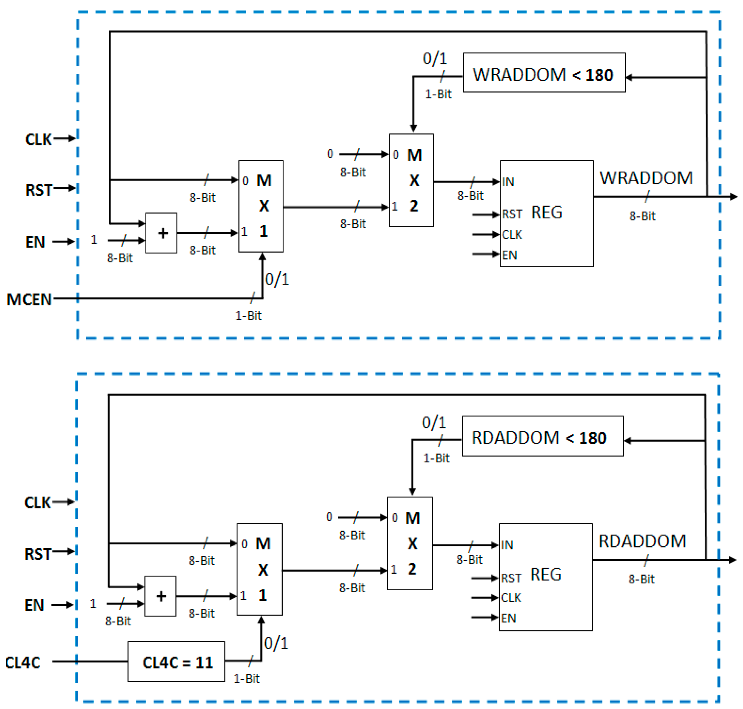
Figure 19.
Write enable signal generation logic for two output memories.

Figure 20.
Logic modules to generate different control signals required for synchronization and proper functioning of complete motion detection system.
Figure 20.
Logic modules to generate different control signals required for synchronization and proper functioning of complete motion detection system.

Figure 21.
Complete motion detection system setup.
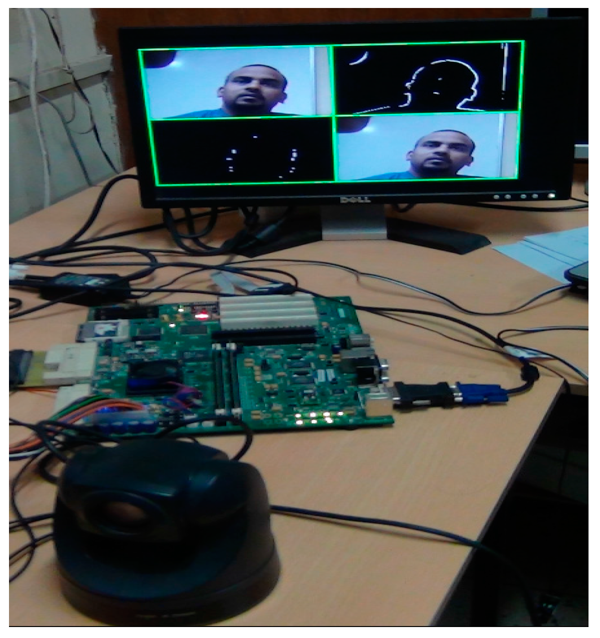
Figure 22.
(a–d): Moving objects in video scene and corresponding motion detected outputs for static background scenarios.
Figure 22.
(a–d): Moving objects in video scene and corresponding motion detected outputs for static background scenarios.

Figure 23.
(a)–(d): Moving objects in video scene and corresponding motion detected outputs for pseudo-stationary background scenarios.
Figure 23.
(a)–(d): Moving objects in video scene and corresponding motion detected outputs for pseudo-stationary background scenarios.

Table 1.
Comparison of FPGA Resource Utilization by the Implementations of Proposed Memory Efficient Architecture and Original Algorithm’s Architecture.
Table 1.
Comparison of FPGA Resource Utilization by the Implementations of Proposed Memory Efficient Architecture and Original Algorithm’s Architecture.
| Resources | Original Architecture [24] | Proposed Memory Efficient Architecture | Percentage of Reduction |
|---|---|---|---|
| Slice LUTs | 1379 | 960 | 30.38% |
| Occupied Slices | 467 | 354 | 24.20% |
| BRAMs 36K | 168 | 99 | 41.07% |
| Memory (Kb) | 6048 | 3564 | 41.07% |
Table 2.
FPGA Resource Utilization by Our Memory Efficient Motion Detection System.
| Resources | Camera Interface | DVI Display Interface | Proposed Memory Efficient Architecture | Complete System | Total Available Resources | Percentage of Utilization |
|---|---|---|---|---|---|---|
| Slice Registers | 391 | 79 | 506 | 983 | 81,920 | 1.20% |
| Slice LUTs | 434 | 101 | 960 | 1492 | 81,920 | 1.82% |
| Occupied Slices | 199 | 33 | 354 | 597 | 20,840 | 2.86% |
| BRAMs 36K | 3 | 0 | 99 | 102 | 298 | 34.23% |
| Memory (Kb) | 108 | 0 | 3564 | 3672 | 10,728 | 34.23% |
| DSP Slices | 3 | 0 | 0 | 3 | 320 | 0.94% |
| IOs | 16 | 22 | 36 | 36 | 840 | 4.28% |
Table 3.
Performance Comparison with Existing Motion Detection Implementations.
| Target FPGA Device | Implementation | Maximum Frame Rate (fps) for PAL Resolution Videos |
|---|---|---|
| Virtex5 (xc5fx130t-2ff1738) | Our Implementation | 372 |
| [24] | 178 | |
| Virtex6 (xc6vlx75t-3ff784) | Our Implementation | 511 |
| [25] | 456 | |
| Virtex5 (xc5vlx50-2ff1153) | Our Implementation | 372 |
| [25] | 315 | |
| [27] | 121 | |
| [28] | 113 | |
| Virtex-IIPro (xc2pro30-5ff1152) | Our Implementation | 230 |
| [29,30] | 200 |
© 2017 by the authors. Licensee MDPI, Basel, Switzerland. This article is an open access article distributed under the terms and conditions of the Creative Commons Attribution (CC BY) license (http://creativecommons.org/licenses/by/4.0/).
Share and Cite
MDPI and ACS Style
Singh, S.; Mandal, A.S.; Shekhar, C.; Vohra, A. Memory Efficient VLSI Implementation of Real-Time Motion Detection System Using FPGA Platform. J. Imaging 2017, 3, 20. https://doi.org/10.3390/jimaging3020020
AMA Style
Singh S, Mandal AS, Shekhar C, Vohra A. Memory Efficient VLSI Implementation of Real-Time Motion Detection System Using FPGA Platform. Journal of Imaging. 2017; 3(2):20. https://doi.org/10.3390/jimaging3020020
Chicago/Turabian StyleSingh, Sanjay, Atanendu Sekhar Mandal, Chandra Shekhar, and Anil Vohra. 2017. "Memory Efficient VLSI Implementation of Real-Time Motion Detection System Using FPGA Platform" Journal of Imaging 3, no. 2: 20. https://doi.org/10.3390/jimaging3020020
Note that from the first issue of 2016, this journal uses article numbers instead of page numbers. See further details here.