The Academy Color Encoding System (ACES): A Professional Color-Management Framework for Production, Post-Production and Archival of Still and Motion Pictures


1
CISSP, Media and Entertainment Technology Consultant, 00100 Rome, Italy
2
Department of Mathematics and Computer Science, John Cabot University, 00165 Rome, Italy
3
Agency for Digital Italy (AgID), 00144 Rome, Italy
J. Imaging 2017, 3(4), 40; https://doi.org/10.3390/jimaging3040040
Submission received: 24 July 2017
/
Revised: 12 September 2017
/
Accepted: 13 September 2017
/
Published: 21 September 2017
(This article belongs to the Special Issue Color Image Processing)
Abstract
:The Academy of Motion Picture Arts and Sciences has been pivotal in the inception, design and later adoption of a vendor-agnostic and open framework for color management, the Academy Color Encoding System (ACES), targeting theatrical, TV and animation features, but also still-photography and image preservation at large. For this reason, the Academy gathered an interdisciplinary group of scientists, technologists, and creatives, to contribute to it so that it is scientifically sound and technically advantageous in solving practical and interoperability problems in the current film production, postproduction and visual-effects (VFX) ecosystem—all while preserving and future-proofing the cinematographers’ and artists’ creative intent as its main objective. In this paper, a review of ACES’ technical specifications is provided, as well as the current status of the project and a recent use case is given, namely that of the first Italian production embracing an end-to-end ACES pipeline. In addition, new ACES components will be introduced and a discussion started about possible uses for long-time preservation of color imaging in video-content heritage.
Keywords:
ACES; scene-referred; output-referred; color gamut; transfer characteristic; reference rendering transform; look modification transform; color look-up table; ColorLUT; Color Decision List; technicolor; primaries; illuminant; white point; film look; VFX; Input Transform; Output Transform; RRT; LMT; interoperable master format; CLUT; LUT; CDL; IMF
1. Introduction
As the acronym indicates, the Academy Color Encoding System (ACES) is a system championed by the Academy of Motion Pictures Arts and Sciences’ Science and Technology Council (hereinafter referred to as AMPAS, or as simply “the Academy”), whose head organization is best known to the world for setting up the annual Academy Award, aka “the Oscars®”. ACES is about Color management in a broad sense, as it is laid out as a series of technical and procedural documents describing how to generate, encode, process, archive imaging content (especially moving images) in an interoperable and standardized way [1,2,3,4].
The moving picture industry has only recently transitioned from a (mostly) film-based ecosystem, with certain “traditional” business logics and industrial scales, to a fully digital one ([5]) with all its disruptive methodologies regarding dematerialized content processing and security. This includes geographical, temporal, technological and marketing segmentation of industry services that are, nowadays, more akin to those of commercial/consumer digital markets. This also led both studios and indie productions (each with different timescales and budgets but converging toward the same solutions, as typical for this kind of economy) to turn to “pay-as-you-go” services and to the global market of service providers [6,7,8]. I am referring here to services deployed using Cloud business models, where almost no capital expenses are required (servers, storage, infrastructure, connectivity), in favor of metrics-driven operational costs, based on actual usage and production volume. Despite this shift raising understandable information-security concerns [9], this has already proved to be a key advantage, because it provides cost savings in production and postproduction as well, due to the increased flexibility, re-usability and global scope of digital technologies. Just to name two examples related to the present paper: the intent of the DoP (i.e., the cinematographer/director of photography or, as Storaro suggests calling it [10], the author of photography) can now be immediately checked “on-set”, and the “look” of the film tailored since the beginning. This is achieved by means of a pre-grading workstation (with a calibrated reference monitor), without waiting weeks after the set is closed and look decisions are definitely moved into the post-production laboratory, Section 2.3 [11]. Second, due to the increase in global, faster Internet connectivity and secure file-transfer technologies, studios can easily distribute workloads for thousands of visual-effect shots (VFX), for each of their movies, among several companies around the globe, with the benefits of:
- sharing financial and content-security risks,
- reducing production times, and
- improving realistic outcome of the overall Computer-Generated Imaging (CGI), due to the differentiation of assets among several artists and VFX companies.
The downside of these new industrial-scale processes, worsened by the rapid inflation of digital tools emerged even before economically-feasible workflows (e.g., cloud media processing), is the lack of technology standards and procedures. These bred and evolved into an ecosystem with lots of vendors, producing proprietary technologies on one side (mostly incompatible with other vendors’ products), and facilities using methodologies with radically different basic approaches on the other—sometimes even different nomenclature for the same things. As for that past in which fewer and bigger film laboratories owned patented frame formats and secret photochemical processes [12,13], this habit has continued in the digital age, leading to a plethora of new trade secrets and color processes, mostly incompatible with each other, and almost without any written formal procedures. This is especially true about color management (or “color science”, as it is sometimes called, often abusing the scientific approach), which is a delicate process that, when not appropriately tackled with, easily leads to quick “patches” to overcome subtleties in things like camera matching, monitor/projector color-calibration, color-space conversions, inter-facility color pipelines, etc. All these patches lead to very specific color processes, rarely transportable across further shows, or translated for different engineers and/or software. As said at the beginning of the paragraph, while this may have had some business/marketing sense in the film era (in the role of Technicolor color consultants, for example, [12,13]), it is now just a threat to the average lean digital workflow.
It is exactly in this context [14], that ACES was born back in 2004 by an effort of the Academy which, like it did in the past many times with theatrical technology breakthroughs (panoramic film projection formats, stereo and multi-channel sound systems, etc., cfr. [12]), coveted a group of scientists, engineers, cinematographers, VFX technical directors and other industry professionals, to find an accessible and vendor-neutral solution to the problem of moving picture color management. This time for the first time, the Academy-proposed solution lives in the realm of “(color) metadata”, is completely digital, open-source and supported by current internet/collaborative methodologies. The ACES project, initially called IIF (Interoperable Interchange Format), was then renamed “ACES” in 2012, when the author also officially joined the Academy internal group of experts. The first official version labeled 1.0 was released in December 2014 [1,15]. In fact, ACES ideas, software, formulas and techniques had been circulating among more experienced users and some vendors ever since earlier versions of it, so these are now usually addressed as “pre-release ACES”, as they may involve legacy terminology and standards. The whole ACES framework will be introduced in Section 3.
The author has been mostly providing color-science consultancy to ACES’ core internal components (cfr. color-spaces in Section 3.3 and the Reference Rendering Transform in Section 3.5) and—thanks to consolidated experience as technology executive for postproduction/VFX companies—technology expertise on the design of metadata integration of additional ACES components (LMT, CTL, CommonLUT, ACESclip in Section 3.6, Section 3.7, Section 3.8 and Section 3.9) and file storage (Section 3.10). As of 2017, he is also cooperating with UK-based company The Foundry (London, UK) for the implementation of additional features introduced with ACES 1.0 (Section 3.8 and Section 3.9) within their Nuke family of compositing, CGI texturing and image-processing software.
At the time of writing, more than 120 films (mostly theatrical, but including TV series/movies, documentaries and short films) were shot using ACES, with a similar figure estimated out of commercials and video art as well. Video games and virtual/augmented reality (VR/AR) are soon also expected in ACES, due to recent efforts to bring professional color management to those industries.
2. The Color Pipeline in the Post-Production and VFX Industry
In this section, several concepts in motion picture digital color management will be introduced or reviewed. They have a general validity even in contexts where ACES is not employed, but this chapter serves as both a background introduction for readers not acquainted with these industry-specific problems, and a pretext for introducing some colorimetry definitions and the terminology used throughout. Extensive, yet not exhaustive bibliographical references are given. The color issue introduced in Section 1 resides in three key areas of the below media production value-chain, cfr. Figure 1.
2.1. Input Colorimetry
Professional digital cameras usually record images using not only proprietary “raw” file formats (including compression and de-mosaicing algorithms [3,16]), but also proprietary imaging and colorimetries designed to account for camera sensors’ characteristics and, possibly, counteract their technical weaknesses. This leads to a plethora of new color-spaces whose optical/digital definitions are, at best, only partially disclosed by camera manufacturers, e.g., ARRI LogC Wide Gamut, RED dragonColorm redLogFilmn/Gamman, Sony S-Logm S-Gamman (m,n = 1,2,3 according to the camera manufacturers’ color-science versions or generation of the sensors), Panasonic V-Log, GoPro CineForm/ProTune™, etc., cfr. Figure 2 and [17]. The native plates for most of the cinematic content are thus born digitally in these partially undefined spaces, but have one thing in common: they use a scene-referred colorimetry [3,18]. This means that each point-coordinate in the color-space—and the integer or floating-point code-value (CV) representing it in the dots of a digital raster—is related to a specific luminance value; its white-point CV is that of a perfect white diffuser [18,19] (as lit by the reference illuminant). The color-space’s transfer characteristic [20] is, in this case, the transfer curve that maps all the luminance values from full-dark to full-white, into the (supposedly greyscale) CVs representing them.
2.2. Creative-Process Colorimetry
Postproduction software vendors are usually required to sign Non-Disclosure Agreements (NDAs) with the camera manufacturers in order to access codebase and information to process such formats; sometimes Software Development Kits (SDKs) are only provided to them, so all the “raw” processing is really black-box modeled further down the media-processing pipeline. Even without dealing with intellectual property (IP) and marketing mechanisms, the additional problem of preserving the original footage and its colorimetry (due to the obsolescence of proprietary colorimetries and raw file formats) is evident. Figure 3 shows the non-trivial, internal color-processing steps that average color-correction systems perform in the background, for when original camera colorimetry is processed to be correctly viewed. Real-world videos usually include cuts sourced from different cameras (not only film, TV, and advertising; photographic or animation; for instance documentaries and news); usually including partial- or full-CGI imaging composited over photographic plates [3]. Video editing, color-correction, compositing, as well as well as 3D CGI software must not only feature processing capabilities for as much of the above file formats and color-spaces [21], but also be flexible enough to accommodate for a wide range of color pipelines that were designed with many different kinds of constrains in mind (from budget, to filming locations/schedules, to hardware/software equipment used on-set and in postproduction, to artists/engineers’ preferences). Color management is often problematic as not all the above solutions interoperate with each other—sometimes not even in nomenclature or user experience (UX). More on this will be detailed in Section 2.4.
2.3. Output Colorimetry
Throughout all the imaging pipeline, from generation (camera or CGI) up to the delivery of masters, the same picture may not only be technically represented in different color-spaces and encodings according to the specific processing stage, but is actually viewed and creatively judged via different displaying devices, set in variegate viewing environments and employing a number of different optical mechanisms to reproduce the light. For this reason, the output colorimetry is called display-referred (or more generically, output-referred) [3,18]. Dually to scene-referred colorimetry, this means that color-space intensity and CVs relate to the luminance level as either directly produced by an additive-light device (monitors/displays), or by measuring the subsequent reflection of the projected light off a screen (theater projector); the transfer characteristic is physically the inverse of the one in Section 2.1; the above light source, at full power, is considered the “virtual scene illuminant” and the measured white is considered the color-space white-point [20]. For this, and accounting for other nonlinearities in the different color-reproduction physics, a change in the luminous intensity of a monitor or projector lamp, may change the output colorimetry, justifying peak luminance as another possible parameter for it. It is measured in SI unit cd/m2; sometimes in US custom unit nits or foot-lamberts (fl), where 1 cd/m2 ≡ 1 nit = 0.2918 fl. In the case of projected light (e.g., in a digital cinema or grading theater), the transfer and the illuminant’s spectral characteristics depend on those in the whole light path: lamphouse and lens first, the glass of the booth (if any), and especially the wide-screen which light is reflected off (effectively considered the 100%-white). The screen may, in fact, have micro-perforations or even metallic threads to preserve reflected-light polarization for some stereographic (S3D) theater systems. Environmental light comes also into play due to color adaption.
From on-set reference monitors (dependent on the location’s lighting, when not inside tents), to the reference monitor of the dailies’ colorist (usually near-set), to the producers’ tablets for review process, to the editor(s)’ monitors, to the grading theater/room—original footage may undergo additional processing like “raw development”, noise/grain management or pre-grading. Then, parallel to color-grading and happening in one or more phases (more on that in Section 2.4), pictures may receive VFX or generic CGI, involving other artists creating rigged, animated, lit, and rendered 3D models and compositing them onto the plates, so that the different moving images realistically blend together [3]. As already said, this is usually demanded across several artists at the same time (sometimes at different studios), each having to evaluate the original look so that artificial pictures (and photographic plates) are all part of the same story. Last but not least, the imaging pipeline ends with the production of several masters, each for every end viewing typology (theatre, HDR/SDR TV, web, print, etc.) other than due to different localizations (audio, subtitles/closed-captions, cards/inserts, main/end titles); see Figure 1 for a diagram showing the steps of the post-production processes. All the above steps take place in different viewing conditions; color-critical operations are made at different times, by different subjects (artists but also imaging technicians); it is paramount that the initial creative intent (the DoP’s) is preserved independently from viewing device and environment. The control of colorimetric process is a key requirement for this industry.
The color-correction, or (color) grading phase is the most delicate, cfr. [20,22], Section 2.4. It is set in either a dark-surround Digital Intermediate (DI) theatre equipped with a digital cinema projector in case of theatrical movies, or a TV grading room, dimly lit and equipped with one or more monitors (cfr. Figure 4a). Projectors and monitors (not only those in the grading theatre/room) are all color-calibrated according to their own reference color standards, dynamic ranges and viewing environments, cfr. Table 1 (and Figure 2). For multiple-delivery shows (e.g., theatrical, web, then SVoD and TV, both HDR and SDR), several color-grading sessions are needed, because there is not yet a universally-accepted HDR-to-SDR gamut-mapping algorithm [19], that is satisfactory from the creative standpoint—and automatically scales to different shows. The colorist first does a “master grade” (usually in the widest-gamut output/display color-space possible, so it is in fact an HDR-grade); this leads to a über-master, which derivative grades and subsequence masters descend upon [23]. The above is not yet a universally accepted standard practice (sometimes the HDR grade is a secondary grade), especially if several masters are needed for different HDR technologies.
2.4. Digital Color Grading Process
As introduced in Section 2.2 and Section 2.3, when “conformed” (i.e., online-edited, high-resolution) footage is color-corrected, the clips in the timeline are each read from proprietary raw file formats, interpreting the “camera-native” color-spaces of their (possibly multiple) sources. Ideally these are the working color-spaces for grading as well: they are scene-referred and feature a pseudo-logarithmic transfer curve (Section 2.1): therefore, they are usually called “log” spaces. This nonlinearity is usually accounting for many optical and electronic phenomena, including the sensor’s tone response curve, an optimization of its exposure range (measured in EV) into the CV space (i.e., the digital representation of the color-space [20,31]), plus the nonlinear effects of vision with respect to illumination which is, trivially by its own definition [32], photometrically “linear”. To view and evaluate the look of the pictures, a color-space transformation to the output colorimetry (as described in Section 2.3) is automatically applied by the color-correction system, cfr. Figure 3.
The application of creative color transformations is operated with traditional computer aids (especially tablet) with the aid specific “control surfaces” (Figure 4); their trackballs and jogs allow for independent, either shadows/midtones/highlights, or RGB-components operations, thus called 3-way CC. Those applied on the whole frame of a video sequence are historically called primary grades, vs. the ones applied on specific subjects or areas of the frame and eventually moving with them along the timeline—which are called “secondaries” [22]. Sophistication of modern color-correction technology does neither depend only on pure color-handling tools—e.g., making secondaries’ partial selections according to either geometries (windows), specific shades or gradations of other colors within the image (keys) or by hand-painted masks (mattes)—nor on the algorithms to automatically “follow” the corrections along with the motion picture flow (power windows and point-tracking in general); current color grading tools (and in this sense both I prefer the use of the noun “grading” instead of “correction”) also take care of the image “look” in a broader sense, including what is referred to as creative finishing [23], including other creatively “dosed” imaging processes on the footage like motion blur, re-graining (i.e., adding artificial film grain—or adding it back after sensor noise or real film grain was removed/polished prior to VFX work [3]), texturing and glow effects, etc.
Color-metadata technologies like the American Society of Cinematographers’ Color Decision Lists (ASC CDL [33,34]), allow the colorist to start from the creative “look” information as it was pre-graded during principal photography [35], thus channeling, if correctly transitioned in the color pipeline, the DoP’s creative intent without the need of “burning” the pre-grades in additional, time- and storage-expensive renders of the whole footage: 10 floating-point values per grade (a single CDL), collected and transferred as either a sidecar XML file or embedded in other video-editing project files, are enough to preserve this color-critical, creative information as tiny-footprint metadata. This is a winning strategy that ACES uses as well [15,16,35]. The core of an XML-embedded CDL is like:
<ColorCorrection id="ClipName_or_CorrectionName">
<SOPNode>
<Slope> 1.06670 1.05820 1.06270</Slope>
<Offset>−0.07250 −0.05260 −0.05060</Offset>
<Power> 1.04020 1.06050 1.06350</Power>
</SOPNode>
<SatNode>
<Saturation> 0.85000</Saturation>
</SatNode>
</ColorCorrection>
The 10 numbers are (s,o,p,σ) ≡ ((sr,sg,sb), (or,og,ob), (pr,pg,pb), σ)∈[0,+∞[3 × 3 × [0,+∞[3 × ]−1,1], grouped in 3 groups of 3-tuples, plus 1 number; the 3 groups each store one parameter type for the color-correction Equation (1), which acts the same on each channel of input color c ∈ 3. The first tuple stores “slope” values s, the second “offset” values o, the third tuple “power” values p; the first coordinate of tuples applies to red, the second to green and the third to blue channel. The tenth number σ is a “saturation” modifier. Overall, the CDL—i.e., the Slope-Offset-Power Equation (1), plus saturation—is applied as Equation (2):
Overall, the CDL—i.e., the slope-offset-power Equation (1) plus saturation—is applied as Equation (2):
Inversion of a CDL is possible in closed form but, unless σ = 0 and p = 13 ≡ (1,1,1), it may not be a CDL itself: the four operations Equation (2) are to be applied in reverse order (inverse saturation, reciprocal power, opposite offset, reciprocal slope). Algebraically, the set of possible CDLs does not form a group.
Both technical color processing (e.g., color-space conversions) and primary grades applied for creative purposes may be approximated by ColorLUTs, cfr. [2,16], Figure 5: color look-up tables were sampled source CVs are mapped to target ones, while colors not in LUT are mapped by interpolation methods (usually trilinear and tetrahedral); among them, 3D LUTs allow better representation of both technically-complex and creative transforms [3] and Figure 6, e.g., some creative looks, or emulation of cross-talk in developed film dyes [13]. Coarser samplings improve accuracy, but not all the systems can handle larger LUTs and their interpolation in real-time, especially if they use floating-point instead of integer arithmetics (cfr. Section 3.3). Furthermore, source shaping the source color mesh along the aforementioned intrinsic nonlinearities of imaging processes (illumination, electronics, and vision [19]) optimizes performance by adding accuracy just where perceptually and numerically advantageous.
ColorLUTs and CDLs are just two examples of color metadata, as they can describe most color transforms in a non-destructive way (as original images are preserved) and without computational and storage footprint due to rendering new images with those transformed “burned” over the raster.
To tackle with all this, color science comes into play, and before ACES were adopted, no single solution existed to be re-usable show after show. Color scientists had thus to provide effective methods and workaround to overcome lots of different optical, psychovisual and digital issues at the same time. This was feasible only in larger imaging/postproduction companies (usually those that had naturally been dealing with color consistency for “traditional” Digital Intermediate (DI) process [31], starting with digital 16/35 mm film scans and ending with 35/70 mm film-out) that had expertise and resources, for example, to engineer ColorLUTs. Smaller production had to rely on non-tailored processes with little to no control. This boosted the industry though, forcing creation of a common vocabulary first [32,36], then standards to refer to display colorimetries [18] and correctly measure their deviation [37]. Overall, color science ensures uniformity of the color pipeline (possibly “from set to screen”) by controlling processes like:
3. ACES Components
First of all, ACES “core” components, i.e., documentation, code and reference images, can be downloaded from both AMPAS’ website [4] and its GitHub page [43]. The Academy also created a specific website called ACES Central [44], which is, at the same time, a repository for all the above, a showcase for all the news related to ACES (e.g., new events and lists of projects and products using it) and, last but not least, a forum-style network where people can ask questions and exchange feedbacks and tricks with both ACES experts and among themselves.
Figure 7 shows a gross bird’s eye view to an end-to-end production/postproduction/VFX workflow, with relevant ACES component names [45] specified for each phase of it.
3.1. Reference Implementation
The “reference implementation” is the ACES corpus, containing everything needed to check that applications of this framework, as well as products built to use parts of it, have reproducible results that are interoperable with those of other products and applications; its components are listed below.
- The ACES documentation is mostly public domain [1,45,46,47,48,49,50,51,52,53,54,55,56,57,58,59,60], plus a group of standards by Society of Motion Picture and Television Engineers (SMPTE) standards which were assigned the ST2065 family name [61,62,63,64,65], plus an application of a different SMPTE standard [66] and two external drafts hosted on GitHub [67,68]. The SMPTE documents are technical standards mainly for vendors and manufacturers to build ACES-compliant hardware and software products; they are not needed by creatives and engineers that just want to use ACES in their workflows and pipelines across production, postproduction and VFX, as this framework was designed with low- and mid-level budget productions in mind. ACES requires neither major-studio budgets, nor top-notch engineers [15].
- The development codebase [43] is an open source implementation of ACES color encodings (in CTL language, Section 3.7), metrics and file formats. It is OS-neutral (although meant to be primarily compiled on Linux and macOS), written in C++ language, plus a few scripts in Python, and depends on a few additional open source libraries [69]. The executables are not intended for production uses—they are neither optimized for performance or batch/volume usage, nor have ergonomic interfaces (being mostly command-line utilities)—but rather for validating third-party products compliance with a reference, as specified at the beginning of the paragraph.
- Collection of reference images as a deck of still photographs about several categories of subjects in diverse lighting conditions, encoded in different ACES color-spaces (cfr. Section 3.3) and using elective file formats like OpenEXR, TIFF and DPX [69,70,71]. Together with the above codebase, ACES vendors and users are expected to test their products and workflows on them and compare them with their own rendered pictures for accuracy in different conditions.
Among the ACES documentation there are three important papers that provide a key to an effective reading of the whole corpus: two [45,47], provide nomenclature and versioning naming convention for the other components (particularly for color transformations in [43]); another one [46], is instead a guide for both users and implementers of ACES as regards usability/user experience (UX) design: ACES needs to be interoperable and vendor-neutral, thus suggestions are made neither about implementation, for example, of products’ user interface (UI), nor on internal algorithms; however a consistent UX is still needed so that users of different products may confidently switch from one to another without having to invent missing parts of workflow that glues them or having to guess equivalent component names across products.
It is in this setting that Sony ImageWorks Inc. created in 2003 an open-source project called OpenColorIO (abbreviated to OCIO) as unified color management frameworks dedicated to VFX [72]. It is supported by most CGI software vendors and also integrates ACES color transforms (despite not all its usability conventions [45,46] are currently respected), so every product supporting OpenColorIO (e.g., The Foundry Nuke, Autodesk Maya®, SideFX Houdini™), basically handles ACES color science as well, at least as far as color-space conversions are concerned.
3.2. Product Partners and the Logo Program
In addition to the above, and to foster interoperability across different products and manufacturers, the Academy created a categorization of products potentially using ACES, a list of product partners (i.e., vendors officially providing products supporting it [33]), and a “Logo Program” where vendors can apply their products to and undergo a certification path for the categories that each products belongs to, eventually receiving an ACES logo for it (drawn at the top-right corner of Figure 7). During the certification, the Academy ascertains that, and the vendor provides evidence for, the product complies with the reference implementation of Section 3.1. This assures to the users that any products with the ACES logo, whatever vendors they are from, are always fully interoperable with each other, so end-user color pipelines can be freely designed without any fear of “lock-in” or color-accuracy problems when switching products among each other.
3.3. ACES Color Spaces
The basics of the ACES framework revolve around a set of “core” color-spaces for which complete and invertible mathematical formulas are specified so that conversions may be applied without any loss of accuracy or precision. In this subparagraph, the color-spaces will be defined and in detail and their generic use introduced; the last color-space, ADX, will be introduced in Section 3.11 as it devoted to photochemical-film color management. Full understanding of ACES color science is delayed to Section 4. Among these color-spaces the first one—ACES2065-1 by the SMPTE Standard [61] defining it—is the most important because it works as principal connection space (or PCS, cfr. [38]) for the whole pipeline; it was also introduced first, well before the others were organically defined. For this reason, ACES2065-1 may still be referred as “ACES Linear” or as “the ACES color-space” in many pre-release implementations of the framework; currently, it is so in the first and former SMPTE standard as well [61], erroneously. Common to these color-spaces (except or ADX, cfr. Section 3.11) is that they are based on the RGB model, scene-referred (cfr. Section 2.1) and the effective white-point is equivalent to that of a D60 standard illuminant (i.e., a 6000 K coordinated color temperature); their gamuts can be defined to be either of two sets of color primaries, called AP0 and AP1 respectively, whose chromaticities are reported in Table 2 and shown in Figure 8 for comparison with other color-spaces.
It is important to stress that, being all scene-referred and wide-gamut color-spaces, they are never meant to be viewed directly on any display device. As usual in traditional motion picture imaging science, they need a color-transform to be applied on top of the color pipeline, just before the output.
The AP0 gamut (cfr. Figure 8a), much like CIE XYZ or CIE RGB [19] is defined to be the smallest triangle enclosing the whole CIE 1931 Standard observer chromaticity diagram, therefore every chromatic stimulus perceivable by the human eye can be represented in this gamut. This choice future-proofs the imaging content of assets stored in ACES colorimetry, no matter how better capture and display devices will improve. The only three caveats in using AP0 are:
- A significant area of the AP0 gamut falls outside of average observer’s (imaginary colors), therefore many CVs are “lost” when these primaries are used in a color-space; besides, most of the in-gamut chromaticities cannot be captured/displayed by current technologies (as of 2017). Thus, a higher bit-depth may be needed to retain the same CV density within a “usable” gamut.
- Since no colorimetric cinema camera exists (yet), and ACES colorimetry is based on this, the correspondence between real tristimuli captured from a scene and the recorded CVs (even before conversion into ACES colorimetry), depends on the manufacturer-chosen sensitometry of today’s real cameras (or on the emulated physics of the CGI application’s lighting engine).
The AP1 gamut (Figure 8) was introduced in ACES 1.0 to overcome the first two drawbacks above; it is a subset of AP0, it does not cover the whole standard observer’s, yet it is “HDR wide gamut”, like ARRI WideGamut, DCI P3 and Rec.2020 (Table 2). In fact, AP1 contains P3 and Rec.2020 gamut used in D-Cinema and HDR reference displays (Figure 2). It represents colors that are viewable on displays and projectors, including HDR, without noticeable color skew. This is the right gamut to apply the internal mathematics of color-grading and CGI applications. It is important to note, however, that colors from AP0 but outside AP1 are gamut-mapped to CVs outside the [0.0, 1.0] range: this is expected behavior and ACES-compliant applications shall handle negative CVs.
In ACES, the colorimetric stance is preservation and future-proofing of moving picture creative intents and, even if it works equally well for “full-CGI” features (e.g., animation), traditional films color-accuracy starts with principal photography, and follows on color-grading. ACES colorimetry is thus scene-referred by design (cfr. Section 2.1) and based on the CIE standard illuminant D60 (which is widely used as “creative white-point”, cfr. [26], Table 1 note 4). Besides, to faithfully reproduce the widest possible dynamic range and extrapolate its interpretation from todays’ imaging technologies, a photometrically linear transfer characteristic (i.e., “gamma 1.0” or color-space linearity) is chosen. Such use of “linear color-spaces” is also consistent with the physics of light, thus notably simplifying image lighting operations on CGI textures, including animation and VFX. Refer to Table 2 for references to documents defining the color-spaces below.
- ACES2065-1 is the main color-space of the whole framework and it is the one using AP0 primaries, since it is meant for short-/long-term storing as well as file archival of footage. It has a linear transfer characteristic and should be digitally encoded with floating-point CVs of at least 16 bits/channel precision according to [73].
ACES terminology introduced in [61] defines a Reference Image Capture Device (RICD) as an ideal/virtual colorimetric camera whose sensor’s spectral sensitivities record scene luminance directly in the above color-space (i.e., linearity between scene relative exposure and CVs) [35]. RICD is defined void of system noise, with 0.5% camera flare off a perfect reflecting diffuser, whose reflected light from a standard D60 illumination source (i.e., a 100% reference-white) is scaled to CV (1.0, 1.0, 1.0), whereas the same recorder light off an 18% grey card maps to CV (0.18, 0.18, 0.18). The viewing environment is always considered observer-adaptive to D60, with 1600 cd/m2 minimum adapted luminance and 0% viewing flare. The next color-spaces are intended as working-only, not at all for storage: compliant appliances shall internally convert back and forth between ACES2065-1 to the sole extent and for the duration of specific purposes only (lighting, compositing, color-grading, video transport).
- ACEScg was specifically designed as a working color-space for CGI applications [74], which it should be the standard working color-space for internal operations that still need linear-to-light transfer characteristic for physics-/optics-/lighting-based simulations. It is different from ACES2065-1 only due to the use of AP1 primaries; conversion to it is done via an isomorphism represented by Equation (3). Encoding uses 16 or 32 bits/channel floating-point CVs (“floats”).
- ACEScc was designed to help with color-correction applications, where a specifically crafted spline-logarithmic transfer function of Equation (4), whose inverse is Equation (5), supports color-grading operators; it applies indistinctly to all RGB channels after a color-space conversion to AP1 via Equation (3). Digital encoding for FPU or GPU processing [34], is in either 16 or 32 bits/channel floats.
- ACEScct is an alternate color-grading space to ACEScc, specifically designed with a different linear/logarithmic spline curve (6) instead of (4), resulting in a distinct “milking” look on shadows, due to additional toe added in that range; this additional characteristics was introduced following many colorists’ requests to have a “log” working space more alike those used in traditional film color-grading and have a similar and vendor-neutral feeling/response when manipulating control surfaces, cfr. Section 2.4 and Figure 3. ACEScc and ACEScct are identical above CVACES2065 0.0078125, although their black pedestal is different (cfr. Table 3 and Figure 9a).
- ACESproxy is introduced to work with either devices transporting video signals (with integer CV encoding), or with intermediate hardware that supports integer-based arithmetic only (instead of floating-point) [34]. These include video-broadcast equipment based on Serial Digital Interface (SDI) among the former category; LUT boxes and references monitors among the latter. Such professional encodings are implemented in either 10 or 12 bits/channel, therefore two isomorphic flavors exist: ACESproxy10 and ACESproxy12. This is the elective encoding as long as it is used only for transport of video signals to endpoint devices (and processing finalized for such intents only), with no signal or data ever stored in, or re-converted back from ACESproxy. By design, it is an integer epimorphism of ACEScc (WARNING: not of ACEScct); it also scales CV to video-legal levels [34] for compatibility with broadcast equipment, as shown in Figure 9b, as they may include legalization or clipping across the internal signal paths. The conversion from ACES2065-1 is done applying (3) first, followed by either one of the two functions in Equation (7) (red for 10-bits/channel or blue for 12-bits/channel).
The color-space conversion formulas between any of the above spaces, except ACESproxy, are exactly invertible because so are matrix (3), and Functions (4)–(6). Conversion from ACESproxy back to ACES2065-1 is numerically possible introducing quantization errors, but this is not allowed as ACESproxy, by design, reserved for transport of color-data to end devices, or within “last-mile” processing inside such devices (with inferior computational performance) just before final output. In no way should ACESproxy code-stream be recovered, recorded, or even stored in files.
- ADX is different from all the other color-space, is reserved for film-based workflows, and will be discussed in Section 3.11.
Color transformations between ACES color-spaces, and between ACES and non-ACES color-spaces, can be implemented by any product, application and workflow according to their specific architectures and pipelines: ACES does not require or suggest any solutions, for the sake of increasing its adoption, and encouraging each actor to freely use the best methodologies and technologies that are considered appropriate, without any limits. In order to verify adherence to the reference implementation (thus assuring interoperability, cfr. Section 3.1), the Academy communicates any color conversion formulas—regardless of its creative or technical intent—via scripts written in a C-style language and both (the language and, generically, the scripts themselves) are called CTL; more on that in Section 3.7. CTL can be used to represent pre-baked color transforms such as ColorLUT, although there is an elective file format for them as well (cfr. Section 3.8). The CTLs coming from product partners (cfr. Section 3.2) are integrated in the next ACES release, thus are automatically retrieved from [43,44] (and, eventually, from [72] as well): new or updated color-spaces get automatic integration into users’ workflows and applications, without needing of full software upgrades.
3.4. Entering ACES
The RICD introduced in Section 3.3 is an idealized colorimetric camera, and the closest “real” thing to it are virtual cameras used in CGI software for previsualization, animation and rendering of assets (although in this case the working space shall be ACEScg). It is, therefore, up to camera vendors to provide conversion formula from their sensors’ native colorimetries into ACES, cfr. Figure 2 and Section 2.1. Any color transformation that takes a non-ACES color-space into ACES2065-1 is called an (ACES) Input Transform (also abbreviated in IDT, whose acronym comes from its deprecated, pre-release name: input device transform). Some manufacturers provide several colorimetries according to different sensor models (or camera firmware), but due to sampling/quantization algorithms getting different firmware-based optimizations as the sensitometry is influenced by user-selectable optical and electronic settings, there may be often several Input Transforms per model, depending on one or more camera settings, like:
- sensitivity, measured in EI (ISO exposure index),
- correlated color temperature (CCT), measured in Kelvin or, equivalently,
- generic shooting illumination conditions (e.g., daylight, tungsten light,…),
- presence of special optics and/or filters along the optic path,
- emulation of the sensor’s gamut of some cameras (e.g., redColor, dragonColor, S-Log),
At application level UIs can be designed such that the selection of the right Input Transform becomes completely transparent to the user: for example, most color-grading software read the source colorimetry and camera settings from the metadata embedded into the raw file headers and use the correct Input Transform accordingly, thus greatly reducing a color-science effort by the users.
The recommended procedure for creating IDTs for digital cameras is described in [55]. Input Transforms can be created for other color-spaces as well, even from output color-spaces (in case one has to bring footage calibrated for an output device into ACES) like sRGB [24], which is the default colorimetry for web-based imaging, as well as those assumed, within motion picture industry, for most of non-color-managed images (e.g., stored in file formats like PNG, GIF, MPEG2, or in JPEG files without an embedded ICC profile).
Any source image can be brought into an ACES pipeline by just applying the Input Transfer corresponding to its colorimetry. This should be the first process and the only place where Input Transforms are used; after that, every image is brought into ACES2065-1 color-space, that is to a photometrically equivalent, scene-referred footage coming from one ideal camera, the RICD.
Product partners manufacturing cameras may provide their own Input Transforms to the Academy for inclusion in the next version of ACES release, so that every other logo-program product can implement those transforms with guaranteed accuracy and without any re-certification, cfr. Section 3.2.
3.5. Viewing and Delivering ACES
As hinted in Section 3.3, ACES colorimetry is always scene-referred, thus no images shall be viewed without some conversion to an output-referred colorimetry first. In short, stored RGB CVs in any ACES color-spaces are not proportional to any intensities for display/projector color primaries. Conversion from ACES2065-1 to any non-ACES colorimetry is done—dually with respect to input, cfr. Section 3.4—via an (ACES) Output Transform, be it just for viewing or for mastering/delivery purposes. Every Output Transform is the composition of a fixed conversion from scene- to output-referred colorimetry, by means of a Reference Rendering Transform (RRT), whose formula closely resembles that of a tonecurve, plus an output device transform (ODT) which maps the output-referred CVs out of the RRT into specific colorimetry standards, cfr. Section 2.3 and Figure 2.
Since the RRT’s shape definition involves mostly technical but also a few creative decisions: it should be a neutral tonecurve, yet pleasant to look at by default, before any look development starts, plus is should be functional enough so that all color-grading operations can be viewed through it. Due to this, the RRT may change in future versions of ACES (current version as of 2017: 1.0.1); the Academy will always provide the official forward/inverse RRT as individual CTLs as part of [43].
Users just need to make sure that every viewing pipeline has an Output Transform applied before any ACES image is viewed, or any footage is rendered/transcoded into non-ACES colorimetry. No Output Transforms need to be used when footage is rendered to “stay” within ACES’ color-managed pipeline, also because the involved ODTs are, usually, highly non-invertible.
Product partners manufacturing viewing devices such as monitors and projectors can provide their own ODTs to the Academy for inclusion in the next version of ACES release, so any logo-program product, cfr. Section 3.2, automatically includes the relevant Output Transforms, as soon as the updated versions of either ACES and OpenColorIO are re-linked from or replaced into the color-managed applications. That may be a bit more complex for some kinds of HDR monitors that adapt the output dynamic range in real time, based on the exposure range of currently displayed/projected content; this process may involve transport of metadata describing changes in the gamut [75]; in this case a separate Output Transform is required, at application level, for every dynamic-range interval. UIs, though, can make this additional metadata path completely transparent to the user/viewer.
It is important to point out the difference between an Output Transform (logically, inverse function of an Input Transform, Section 3.4) and an ODT: the former is the combination of the RRT plus an ODT; for this reason, the former is informally called “RRT + ODT”, as in Figure 10. These are unessential technicalities, but subject to the improper nomenclature used in pre-release ACES.
3.6. Creative Intent in ACES: The Transport of “Color Look” Metadata
ACES colorimetry is intended for all color-critical processes and, being based on standardized color-spaces (Section 3.3) with fully invertible cross-conversion formulas, the interoperability is guaranteed as long as images are transported in this colorimetry; creativity is not hindered by technical constrains posed by the use of different products, toolsets available to colorists (via product partner products) are ACES-agnostic, so artists can decide exclusively based on creative evaluations, while engineers may remove many technical constrains off the color pipeline. As defined in [56], any “image-wide creative ‘look’ to the appearance of ACES images […] that precedes the” Output Transform is called a Look Modification Transform (LMT); more abstractly, a LMT is any color transformation mapping ACES2065-1 CVs into themselves and applied in between the Input and the Output Transforms (i.e. before the RRT), like in Figure 11a,b. Again from [56]: “LMTs exist because some color manipulations can be complex, and having a pre-set for a complex look makes a colorist’s work more efficient. […] The LMT is intended to supplement—not replace—a colorist’s traditional tools for grading.”
Technically, it may include color-space transformations in between so that the overall action is done within the ACES2065-1 colorimetry, like shown in Figure 11b. As far as creative color modifications are concerned, primary color-grading operations (including those carried over by ColorLUTs or by CDLs, cfr. Section 2.4) can be part of an LMT; closed-form mathematical formulas can be as well. In this case one talks about an “analytical LMT”; when the LMT is mostly originated from a pre-existing technical or creative color mapping (e.g. in the form of a ColorLUT), one talks about an “empirical LMT” instead. Sometimes the grades represent the early or tentative setting for the “film look” [2], coming from on-set grading sessions (and called, in this context, pre-grading [11]); sometimes they represent the complete finished look of a scene; most of the times, the look is just an intermediate passage before more refined finishing is applied to fine-static and moving details. The possibility to save this look as an ACES key component and make it part of the interoperability framework is, however, essential. For this reason, LMTs can be represented, at the low level of the ACES reference implementation (Section 3.1), as CTLs, but they are usually stored using the color-correction software’s own algorithms as well. The Academy provides two interchange formats, for looks/LMTs as well as for generic color transformations, that will be introduced in the next paragraphs, cfr. Section 3.7 and Section 3.8.
3.7. Color Transformation Language
There are two AMPAS-sponsored projects that describe new syntaxes, detailed in the current and next subparagraphs, respectively. The former is the Color Transformation Language (CTL) [67,68], a C-style language (.ctl file extension), that was born with ACES, to describe the widest possible range of color transformations in algorithmic form (i.e., by means of algorithms and numeric formulas); it is organized in “library modules” where CTL files containing higher-level functions may include references to other CTLs defining lower-level functions. A CTL can contain either generic functions for manipulating data (even as abstract as matrix algebra) and production-ready color transformation algorithms; it may or may not reference additional CTLs.
CTL is not intended for production use, because neither the language nor its interpreter, ctlrender (which accepts an image plus a color transform specified as CTL, rendering out that image with the CTL applied, or “baked” in), were designed with parallel processing in mind. For similar reasons, most production-ready hardware and software systems, should not implement direct processing of CTL files; they serve as references which actual ColorLUTs can be built upon and later on processed faster, especially by real-time systems.
The CTL system is not only modular, but also extensible: Academy-provided CTLs, being part of the reference implementation (cfr. Section 3.1), are structured using the filesystem hierarchy under transforms/ctl folder; those of the core transforms in Section 3.3, Section 3.4, Section 3.5 and Section 3.6 can be found in the corresponding subfolders (and grouped therein using subfolders named along with camera vendors or output color-spaces), whereas a generic subfolder ./utility contains the “library” of lower-level mathematical and colorimetric functions commonly used by the other ODTs.
For example, the official LMT.Academy.ACES_0_7_1.a1.0.1.ctl file in [43], containing a legacy sample LMT, does not depend on any library CTLs, as it is essentially a pre-baked 3D LUT, cfr. Section 2.4 and Section 3.6. Let instead the ODT.Academy.P3D60_ST2084_4000nits.a1.0.1.ctl file in [43] be considered (Section 3.5); its filename can be interpreted using [45] as a map from ACES colorimetry version 1.0.1 to a very specific, output-referred color-space for technical mastering/viewing called “P3@D60 (i.e., P3 primaries [26] with D60 white-point (Table 1 note 4)) with SMPTE ST2084 transfer curve [29] and 4000 cd/m2 peak luminance”—cfr. Section 2.3 for technical insights about this output colorimetry. This CTL depends on four CTLs in the ../../utility subfolder, progressively defining lower level formulas:
- used in most ODTs (e.g., white roll, black/white points, dim/dark surround conversion);
- the RRT itself, including generic tone-scale and spline functions contained together with it;
- basic color-space linear conversion formulas (plus colorimetry constants);
- functions from linear algebra and calculus (plus a few mathematical constants).
A single ODT file may have a (commented) XML tag <ACESTransformID> whose element is the ODT’s original filename itself—but it may be some kind of universally-unique identifier (UUID) or, in the future, some hash-digest or other message integrity code (MIC). Color-management applications may honor this tag in order to properly index and identify CTLs within larger databases, possibly retrieve legacy ones from a registrar/repository—whereas only newer versions may be shipped along with the reference implementation—and, in case of hash/MIC, validate the transforms to double-check they were not altered or corrupted (which is essential if CTLs are all remotely stored, for example, for IP protection reasons—cfr. Section 2.2).
3.8. CommonLUT Format
The latter file format/language, sponsored by both the Academy and the ASC, is the CommonLUT Format (CLF) [51,68], which is a XML dialect for storing both exact and approximated color transforms (like ColorLUTs [2,16] and CDLs [33], cfr. Section 2.4), as well as their combinations. This is suggested as elective interchange file format for ColorLUTs in ACES workflows, and an open SDK in Python is also available [43] as reference implementation for bi-directional conversions between CLF and other open or proprietary ColorLUT file formats used by current commercial software. CLF also has the following features:
- combined, single-process computation of ASC CDL, RGB matrix, 1D + 3D LUT and range scaling;
- algorithms for linear/cubic (1D LUT) as well as trilinear/tetrahedral (3D LUT) interpolations;
- support for LUT shapers (cfr. Section 2.4) as well as integer and floating-point arithmetics.
More features will be implemented in the next versions of CLF, like other technical and authoring metadata (to better characterize source and target color-spaces), new color transform paradigms (including direct CTL referencing), new interpolation methods, and integration with Academy-provided color transforms (via ACESTransformID tag, Section 3.6). Expansion of the CommonLUT format is also one of the author’s main contributions to ACES, particularly on color-metadata extensions and on interpolation algorithms using advanced Algebraic Topology techniques based on simplicial geometry, cfr. [20,76,77]. As of 2017, CLF has received mild support by a few commercial color-correctors (e.g. Light Illusion LightSpace), mainly because most of the algorithms behind its main process nodes can hardly be applied in real time on footage being played back. Yet, some vendors adopted CLF, and then further extended it, into real-time proprietary file formats for their color-grading, finishing or CGI modeling software: CTF file format for Autodesk® Smoke®/Maya® and DCTL file format for Blackmagic Design DaVinci Resolve.
3.9. ACESclip: A Sidecar for Video Footage
Version 1.0 of ACES introduced a very important addition to existing color management frameworks for Media and Entertainment, in the form of the (ACES) Clip-level metadata file, briefly called “ACESclip” [58]. Despite a current scarce implementation by product partners, this “sidecar” file is meant to be generated for each video clip entering (even just formally) an ACES pipeline, and stay along with it any futur re-renders, at least for as long as the clip logically resides in an ACES-color-managed environment. In this context, a video clip may be either a “frame sequence” (i.e., a sequence of still-picture files with a consistent, consecutive and uninterrupted enumeration in their filenames, where each file progressively represents one frame of a locally-referenced video sequence—e.g., {frame-0001.ari, frame-0002.ari, …, frame-0859.ari} for a sequence or ARRIRAW files [78], containing one clip recorded by an ARRI Alexa motion picture camera), or a single video file (e.g., the file A050_C029_0803HB_001.R3D containing one clip recorder by a RED Dragon camera, cfr. Section 2.1). An ACESclip is an XML-language file that persists for every such clip, acting as both a manifest file, i.e., storing metadata about the clip that may or may not be stored within the clip’s file(s) header, and as a sidecar file, i.e., ACESclip’s locality-of-reference with its clip shall be maintained by storing it in the same folder as the clip and with the clip’s own filename, plus .ACESclip.xml extension appended, cfr. Figure 12.
In the former, frame-sequence case above, that is frame-.ari.ACESclip.xml; in the latter, single-file case, it is A050_C029_0803HB_001.R3D.ACESclip.xml.
ACESclip also has an XML namespace reserved to it: aces. This component may be needed in contexts where either the clip’s file-format does not support fields where relevant color-related metadata can be unambiguously stored, or this association cannot be enforced (e.g., such fields exist in the file headers but not all applications honor them or expect such information as written according to a standard encoding, etc.), or the conversion of the clip to file format allowing such metadata in the header is impractical (due to time, storage and/or computing constrains). Keeping the (original camera) footage in its native file format(s) and colorimetries, while adding missing information in an ACESclip, is always advantageous for the same parenthesized reasons. Despite the ACES framework specifies file formats for storage of ACES footage, read Section 3.10 and [64,65,66], such formats are not mandatory in order to be ACES color-managed; original camera footage, for example, may be usually stored in its original raw format (Section 2.1), untouched; ACESclip comes in handy especially in this context, where a record of the colorimetry and color transformations that the clip has either undergone (in the past), represented in its present state, and likely to be interpreted (in the future) for viewing/mastering purposes may be advantageous. Information should also be present in ACESclip to unambiguously re-associate it to its original clip in case the above locality is lost (e.g., the ACESclip file is separated from the clip itself), although ACESclip should stay along with its content throughout its entire lifecycle (until archival and/or destruction). Information stored in the sidecar file includes:
- reference to the clip itself by means of its filename(s) and/or other UIDs/UUIDs;
- reference to the Input Transform either used to process the clip in the past or intended for entering the clip into an ACES pipeline in the future;
- reference to LMTs that were applied during the lifecycle of the clip, with explicit indication whether each is burnt on the asset in its CVs, or this a metadata association only;
- in case of “exotic” workflows, the Output Transform(s) used to process and/or view the clip.
References to the above color transformations like Input/Output Transforms and LMTs are made by either linking the CTL’s ACESTransformID (if any), or directly writing the ColorLUT or ASC CDL data as XML extensions, or by using ACESclip’s own XML tags. Future versions of ACESclip will have more features (which is one of the author’s current activities within this project), also thanks to the use of XML, like:
- the clip’s color pedigree, i.e., full history of the clip’s past color-transformations (e.g., images rendered in several passages and undergoing different technical and creative color transforms);
- extending the ACESclip XML dialect with other production metadata potentially useful in different parts of a complete postproduction/VFX/versioning workflow (frame range/number, framerate, clip-/tape-name, TimeCode/KeyKode, frame/pixel format, authoring and © info, …).
An example of ACESclip XML file, reference for namespace and most of its tags, is found in [58].
3.10. Storage and Archival
As written in Section 3.3, storage of ACES footage is allowed in ACES2065-1 color-space only. Nevertheless, files are not always stored or transported in ACES colorimetry and, even if not endorsed in ACES guidelines, many VFX facilities prefer to encode footage, and temporarily store it, in ACEScg color-space for several practical reasons [80]—ACESclip can come in handy to store color parameters that will be used to do both things properly, cfr. Section 3.9.
However, a small group of file formats are defined as elective choices for storing footage in ACES colorimetry (ACES2065-1): within the SMPTE family of standards about ACES, metadata constrains are defined for filesystem implementation as either frame sequences and single video files, cfr. Section 3.9. Stored as file-per-frame sequences (ST2065-4 [54,64]) the open-source OpenEXR still-picture format (“EXR”) is chosen [69]—uncompressed, scanline-based, floating-point 16 bits/channel encoding—plus other specific constrains. Stored as video files (ST2065-5 [65]) the SMPTE MXF multimedia container [81], wraps a series of frames, each encoded as per ST2065-4, plus additional constrains on the MXF internal structure. Table 4 lists all the principal constrains for the above formats.
There has also been a growing interest by studios and OTT companies in encoding mezzanine/master formats preserving the original ACES colorimetry, so that interchange and archival copies are stored in one shared colorimetry. The de-facto standard for this purpose has become the SMPTE Interoperable Master Format (IMF), which has a dedicated family of standards, ST2067 [82]. In short, IMF prescribes that a content—either video, audio, and timed-text (TT) data—to be either exchanged among facilities, long-term archived, or simply prepared for mastering, as per Section 2.3, is organized in a IMP (interoperable master package), i.e., a sub-filesystem structure that may have one or more of:
- video tracks, (monoscopic or S3D stereoscopic);
- sound groups, as separate sets of audio tracks, each with possibly multiple channels (e.g., a sound group may have 3 audio tracks: one has “5.1” = 6 discrete channels, one 2 discrete “stereo” channels and the other a Dolby-E® dual-channel—all with different mixes of the same content);
- TT tracks (e.g., subtitles, closed captions, deaf-&-hard-of-hearing, forced narratives, …);
- one Packing List (PKL) as the inventory of files (assets) belonging to the same IMP, listing their filenames, UUIDs, hash digests and sizes;
- one Composition Play-List (CPL) describing how PKL assets are laid out onto a virtual timeline;
- Output Profile List(s) (OPLs) each describing one output format rendering the IMP into a master.
PKL, CPL and a few other files in an IMP are XML sidecar files, whereas video and audio assets are wrapped in MXF files [81]. The separation between content essences (video/audio/TT clips) and their temporal/logical organization within a timeline (the IMP’s virtual timeline) allows easy interchange of single components for versioning purposes (e.g., localization, assets’ distribution, censorship, etc.). An IMP can, in fact, depend on other IMPs (which it is a “supplemental” package of), so it is easy to build a new cut/edit/mix of a piece of content by having a new CPL referencing essences from several PKLs. As well as MXF standards include “Operational Patterns” that add additional technical and operating extensions to the file format (as regards essence codecs, metadata, internal file structure, interoperability and, above all, usage workflows), IMF standards include numbered “Applications” for specific requirements where, for example, IMPs must obey one or more rules regarding either naming conventions, compulsory metadata, package and virtual timeline structure, etc.
Use of ACES colorimetry with the very versatile and extensible IMF is being standardized in Application #5 [66], including author’s contributions, which prescribes video content encoding in ST2065-5 standard (MXF-wrapped EXR frames in ACES2065-1 colorimetry), plus additional metadata describing the version of ACES and of the core transforms from Section 3.4, Section 3.5 and Section 3.6. Optional reference still-frames, encoded via Output Transform(s) and included in the IMP as either PNG or TIFF files, are linked at specific frames of the virtual track, so that content mastering (at least in the same color-space(s) as the reference’s) can be visually evaluated for consistency in case the content is “restored” in more-or-less unknown conditions. This is a very important (yet optional) feature, as IMF Application #5 deals with packages in ACES2065-1 and purposes them for interchange and even long-term archival, delegating to otherwise unreferenced Output Transforms the task to produce any viewing colorimetry for the content. In a sense, IMF Application #5 is a complement and an extension to ACESclip specifically targeting interchange, versioning, mastering and even long-term archival, as further detailed in Section 6.
3.11. ACES Integration with Photochemical Film Process
A last-but-not-least part of the ACES framework is dedicated to workflows involving film scanning and film-out (i.e., film printing) processes; this part was one of the earliest to be designed—with involvement of digital film-processing labs [23,33]—and is increasingly relevant to film preservation, as remarked in Section 6. A multi-device, yet simple ACES workflow for a DI pipeline, from scan to film-out, is shown in Figure 13. For a complete description of photochemical film-based processes cfr. [12,13]; for a “traditional DI” workflow instead, cfr. [31]. First, a new densitometry for photochemical negative and internegative films is defined, the Academy Printing Density (APD), replacing other standard optical density metrics, like Kodak Cineon™ Printing Density (CPD). For a film printer, APD depends on the overall spectral power distribution (SPD) along the light path (i.e., light source, spectral transmission/reflectance/absorbance of optics, film medium). It has 3 spectral components , one per spectral responsiveness of the printer’s RGB light sources, is numerically defined in [62], and modeled after the Bell & Howell Model C® with Kodak Wratten® filter No. 2B applied—resulting in a variant of Status-M densitometry [83]. It is thus a vector field Πapd∈[0, +∞[3 depending on the film sample’s spectral transmittance T(x,y,λ):
An APD minimum value of 0 means 100% transmittance, thus Πapd = 03 ≡ (0,0,0) corresponds, once re-printed to positive stock (as APD natively refers to negative films), to the deepest printable black. As regards the representation of negative/internegative film scans as digital data, a densitometric color-space called Academy Density Exchange (ADX) is introduced [63], with logarithmic transfer characteristic and integer CVs (10-/16-bits per channel), encoding image data as the APD values of a color negative film that will be printed on recent, average motion picture print stock (i.e., a mix of Kodak Vision®, Fujifilm Eterna® and F-CP®). ADX thus represents quantized film density scanned from a negative film, as it is expected to be printed by a reference printer. ADX is output-referred to a reference print film: all in all, it encodes a “film-referred” color-space.
To compute an ADX CV cadx ∈ 3, the optical density of a film receiving 0 EV exposure, Dmin ∈ 3 (i.e., that very negative film’s clear-base density), is subtracted from the APD triple Πapd of a particular point on the film, then it is quantized according to Equation (9):
A sequence of DPX frames [71], can be used to store film scans in ADX color-space; it is recommended to ensure that the scanner software fills as many DPX Film-Area metadata as possible, including printing-density type (APD), clear-base Dmin and, above all, perforation-wise KeyKode™ (if available). The Academy provides Output Transforms from ADX to ACES2065-1 and documentation on how to calibrate the laboratory’s printing process to ACES colorimetry, cfr. [59], which means matching APD with all the films stocks used in the laboratory’s scanners and printers. PFEs may also be generated out of this—as usual in traditional DI workflows—and become “empirical LMTs”, as described in Section 3.6 and Figure 14.
4. The ACES Color Pipeline, from Theory to Practice
Now that all the ACES components have been defined and general concepts for their use were explained, a more detailed, end-to-end workflow based on ACES 1.0 will be explained (Figure 15), including general processes already introduced Section 2.
In a typical on-set or near-set scenario, footage from the camera is either saved as is, in its camera-native file formats and colorimetries, or can be sometimes converted to ST2065-4-compliant EXRs (cfr. Section 3.10); latter choice is rarely employed because it requires additional storage and computing power which is so critical for on-set operations. Sometimes though, the camera-native format may be unsupported by some of the tools, so a priori conversion is preferable, as long as it does not reduce the footage quality. Viewing of the footage is possible through monitors equipped with view LUTs from the camera-native colorimetry to the on-set monitor colorimetry, but in case of ACES workflows, the monitor reference output from the camera is expected to provide a video signal in ACESproxy to an ACES-compliant monitor that reads that video feed and, once detected, displays it in its right colorimetry. Most professional cameras by RED, ARRI and Sony Cinealta™ have this monitor-out SDI port with ACESproxy colorimetry (so the conversion is internally done by the camera), while the footage is sent to the recorder or to SSD/flash storage in its native colorimetry. If CDLs are applied on-set, the footage should be converted to either ACEScc, ACEScct or, in case a true floating-point capable color-corrector is not available on-/near-set, to ACESproxy. This conversion is necessary because the CDL Equations (1) and (2) encode meaningful color-correction metadata only if operating on CVs of a “log” color-space.
By taking Figure 13 as a bird’s-eye view reference for the video post-production phase, Figure 15 concentrates on color grading. In this case, again, the footage is internally converted via Input Transform(s) adequate to the camera footage, into ACES2065-1; sometimes this passage was done before—either near-set or in the postproduction lab during a preparation phase like data management, digital negative “development”, noise/grain management. Internally, the color corrector applies most the color-grading operations by pre-converting the footage to ACEScc or ACEScct, then applying the transforms (CDLs, 3-way CC, printer lights, lift/gamma/gain, “X-versus-Y”, etc. [22]) and finally post-converting the footage back to ACES2065-1. As said in Section 3.3 and specified in [46], this conversion should be almost (if not completely) invisibly to the user. A very important caveat, though, is that the choice of working color-space to use for color-grading (among ACEScc or ACEScct) should be the same across departments, otherwise the CDL coordinates cannot represent the same color-correction when moving from the set to the post-production lab.
For example, if ACESproxy are employed on-set for CDLs, then ACEScc may be safely used in postproduction because, as per Section 3.3, formula (7) is the “integer-arithmetics analogue” to (4), ACES-compliant CDLs use as transfer characteristic (provided the difference between the video-legal range of ACESproxy is taken care as well). If ACEScct is used in post-production instead (usually on specific colorists’ creative request on the default look of the footage), CDLs generated on-set on top of ACEScc or ACESproxy cannot be used at all: there is no integer-arithmetics, transport color-space analogue to ACEScct.
Primary color-correction is usually applied globally as a LMT, cfr. Section 3.5, so ACESclip sidecar files may be enough to describe and represent such creative operations on the footage. However, color-grading is usually much more complex (as seen in Section 2.4) therefore highly dependent on the color-correction application’s tools and file formats to store project metadata. Although secondary grades and more complex operations are, in fact, not meant for LMTs, they are powerful instruments to help preserve or build more complex looks starting from pre-existing LMTs or other kind of simpler “primary” color operations; for example, empirical LMTs can be built out of pre-existing LMTs—e.g., out of a Print Film Emulation LUT (PFE) created in a film laboratory—and hard-coded (“baked”) as an individual 3D LUT, to replicate advanced color effects and transport them like black boxed in a node-based color pipeline (cfr. Figure 15).
5. Use Case of an End-to-End ACES Workflow in a Full-Feature Film
A real-world use case where ACES was effectively and successfully used, will now be explained, concentrating on the pre-production tests, with the intent to show not only how ACES actually “works”, but that it is a solid and viable option for films with limited budget as well. It may take a while to make everyone comfortable working with ACES color management (from camera to editorial, to VFX, to finishing departments) but—especially if ones does not own an expensive color science department—it really pays off in the end and increases everyone’s trust in what is seen on monitors while jobs are carried on.
During the author’s service as Chief Technology Officer (CTO) of Frame by Frame Italia (a leading theatrical and commercials post-and-VFX company based in Rome, Italy), this company provided video postproduction and VFX services for Indigo Film’s superhero movie sequel Il Ragazzo Invisibile: Seconda Generazione (G. Salvatores, 2017 [84]). After a pre-production meeting with all the above departments involved (including the camera department from Kiwii Digital, the colorist, and the VFX supervisor), it was decided to use a workflow integrally based on ACES version 1.0.3 (as regarded color-science), thus spanning photography, postproduction and VFX. The decision was due to the expected use of ARRI Alexa XT cameras for principal photography (shooting in ARRIRAW frame sequences, uncompressed, 2.8K [78]), plus additional RED Dragon (R3DCODE raw clips, JPEG2000-compressed, 6K) and GoPro (clips in ProTune™ color-space, H.264-compressed, 4K) cameras, thus leveraging on the system’s multi-input compatibility. The author, as both an active color-scientist contributing to the ACES project in first person [51], and for having already conducted camera-comparison sessions for ACES 1.0 compliance before [85], designed two different pre-production tests dedicated, respectively, to the camera department (Kiwii Digital, Section 5.2) and the VFX department (Frame by Frame, Section 5.3), to individually interoperate with the finishing department. The company’s DI theater, equipped with FilmLight Baselight color-correction system (cfr. Figure 4a,b) and a Christie 2K reference projector (DCI P3 color-space, with 14 fl full-white and dim surround color-adaption), as a “hub” for color-critical evaluation. As said in Section 2.4, in fact, the DI theater is where the cinematographer and the colorist spend most of the time developing and finishing the “look” of the movie, in a lighting and viewing environment that is a reference for all movie theaters where film will be screened to the audiences.
The choice of tools across the various phases, and their total compliance with ACES 1.0.3, made this test very straightforward: a fortiori, it simply confirmed that all possible production roundtrips for the film’s color pipeline produce mathematically color-identical results. In the end, no specific “show LUT” was crafted to use as a empirical LMT, because the cinematographer and the colorist liked the default look given by ACES’ default RRT (version 1.0.1, Section 3.5); the only technical 3D LUT that was exchanged with camera department was the Input Transform for the ProTune™ color-space (as GoPro was not an ACES product partner, Section 2.2, at the time of the tests). All cross-department data and metadata paths undergoing ACES processing were therefore tested, as described in Section 5.2 and Section 5.3, with positive outcome.
5.1. Production Workflow and Color Metadata Path
For the above movie, a workflow very like that described in Section 4 was used. The on-set/camera department provides on-set grading, footage backup copies and generate dailies for editorial (using Avid® Media Composer®). For grading the camera department uses ACEScc, as their on-set equipment has full floating-point processing capabilities (ACESproxy is not needed for this workflow), exporting CDLs on top of this space. Dailies are MXF-wrapped DNxHD files, 1080p24@120 Mb/s, encoded in Rec.709 color-space with pre-grades burnt in; Avid project files (“bins”) with all the footage metadata, including the CDLs, are sent from camera to editorial directly. Kiwii Digital also prepares the backup of all original footage (ARRIRAW, R3DCODE, H.264), audio, CDLs other metadata into 6th-generation digital LTO tapes (2.8 TiB per tape) using interoperable LTFS format. The fact that the postproduction facility provides both finishing and VFX services, and hosts the external editorial department (2 editing suites), all within the same premises, helps a lot for intercommunication.
Editorial department produces Avid bins containing references of footage needed for compositing (VFX plates), i.e., the shot scenes that will receive composited VFX over. From the above bins only the relevant footage is restored from LTO6s (plus 15 head/tail handle-frames for each clip), converted into ST2065-4-compliant EXRs, and transferred to the VFX storage. The reason for restoring just the needed clips is economy on the storage footprint (9 MiB per frame); reason for converting from camera-native formats is explained at the end of Section 5.2. At the same time, using in-house Python code written by the author, each VFX plate from the above bin is converted into a new Nuke projects that already include specific high-level automations (further customizable on a show basis), like:
- filesystem naming-convention enforced for input (VFX plate footage) and output files (renders);
- OpenColorIO set as color-management system, with ACES 1.0.3 configuration, cfr. Section 3.1;
- all color-spaces for input footage, optional CGI models, CDLs and render files, automatically set;
- customizations for the specific artist assigned to the job (name, OS, workplace UI, …);
- customizations/metadata for the specific job type (rotoscoping, “prep”, compositing, …);
- set up of a render node that writes both the full-resolution composited plates (as a ST2065-4-compliant EXR sequence), and a reference QuickTime-wrapped Apple® ProRes 4444, with informative slate at the beginning, to use for previz of VFX progress in calibrated UHD TV room;
- set up of viewing path that includes the CDL for each plate node (with ACEScg to ACEScc implicit conversion), just before the Viewer node (implicit Output Transform to the monitor);
- set up of alternative viewing path using a Baselight for Nuke plugin, to previsualize the specific secondary color-corrections from the finishing department (read below).
For the last bullet-point it was decided that, for a few selected shots with complex grading and/or compositing requirements, it is necessary to simulate the full secondaries for exact matching (e.g., a different CC applied to the plate and to the composite, that needs to change as the VFX is prepared, both as CGI and compositing). In this case, FilmLight provides a metadata format called BLG (BaseLight Grade) that exports the full CC of a single shot, as done in Baselight, later to be imported by Nuke or Media Composer® via a node-based plugin. For those selected shots, the in-house tools automatically replace the CDL node with the latter plugin node (referencing the relevant BLG file).
Regarding the color-correction phase, the editorial department sends an Avid bin with the final cut of the movie, and the editing information embedded as metadata (including the CDLs) to the postproduction lab; the conforming phase (cfr. Figure 1) rebuilds, in Baselight, the complete timeline using either the original footage selectively retrieved from LTO6’s, or with the rendered versions of VFX plates (if available, even as temporary versions). As long as the project “reels” are prepared, the colorist and the DoP work on the film look and finishing. Color grading starts from the CDLs and internally works in ACEScc color-space, but produces ACES2065-1 files in the end.
At the end of the project (still ongoing at the time of writing) Frame by Frame provides the finished footage in several delivery formats, including those for long-term archival in the form of both ST2065-4-compliant OpenEXR sequences (cfr. Section 3.10) and DCDM-compliant TIFF sequences, to be archived in 7th-generation LTO tapes (5.6 TiB per tape, LTFS).
5.2. Camera Department Test
First of all, the reference monitors used by the camera department during principal photography are all color-calibrated to Rec.709 (gamma 2.4), and cross-calibration with the reference monitors used in all the other departments was double-checked. The camera department does not alter the original camera footage (that is archived and always worked on in its native color-space, i.e., mostly ARRI LogC WideGamut, into ACES2065-1 via official Input Transforms), while pre-grading and dailies (with burnt-in CDLs) are color-handled on-/near-set. For this reason, during the usual pre-production camera and lens tests, Kiwii shoots a few clips for each used camera type and a few different lighting settings; then processes the footage and renders each of the clips in four variants, {1–4}, differing by color-space and file formats (cfr. Figure 16a for a sample from ARRI Alexa XT camera):
- EXR sequence (ST2065-4-compliant, original resolution), without {1} and with {2} baked CDL;
- DPX sequence, resampled to 2K and Rec.709 color-space, without {3} and with {4} baked CDL.
The finishing department then generates all the variants {1–4} from scratch, via Baselight, from the original footage in their camera-native color-spaces; for each clip, the samples generated in the two facilities are compared both visually (in the DI theater), then technically by pixelwise subtraction of one sample from above the other, as shown in Figure 16.
Comparison of the original footage with {1} and {3} respectively verifies the consistency of the Input Transforms for the ARRI Alexa camera, and of the Output Transform for Rec.709; the above comparisons were indeed not necessary, as they are standard components used across logo-partner products, Section 3.2. Comparison of the original footage with the EXR variant with CDL {2} verifies the implicit ACEScc color-space conversions used by the color-grading processes (both on-set and DI); that with variant {4} verifies the whole viewing pipeline consistency (Input Transform + LMT + Output Transform), i.e., that the on-set pre-grades look the same throughout to finishing.
The tests showed no visible differences, thus confirming effective interoperability. Difference tests were done in floating-point arithmetics, naturally supported by both Foundry Nuke (32 bits/channel) and Adobe® Photoshop® CC (16 bits/channel), and using ACEScg as working color-space—naturally implemented in Nuke via OpenColorIO, and configured in Photoshop® via an ICC profile that was previously compared for accuracy by means of additional software by Light Illusion.
The only detected—yet expected—inconsistency was present, in all variants, in high-frequency and/or high-saturation details of ARRIRAW footage, as seen in Figure 16b. This is not due to color-management disparities though, but rather to the different de-mosaicing algorithms in software products used by the two teams to “remove” the Bayern-pattern, that is the color-grid pattern that is written in each ARRIRAW file that replicates the layout and geometry of photosites in the Alexa camera’s Alev-V sensor, as described in [75]. Demosaicing can be implemented in many ways (e.g., by either CPU or GPU processing [34]), and different accuracy/quality goals; since it is a computationally-intensive process, some color-correction systems employ higher-speed but lower-quality algorithms to prioritize real-time computation of CC operators along with footage playback, while switch to higher-accuracy/higher-quality algorithms for non-real-time operations like rendering the final files. Despite camera vendors either provide SDKs or disclosure of their certified exact algorithms, nor all the products use them, in favor of customized algorithms. The difference is sometimes hardly visible in moving scenes, but can be appreciated in stills, and technically detected in high-detail/high-saturation areas, like in Figure 16b. This is also why, during postproduction, plates sent to the VFX department are pre-converted to EXRs (thus also de-mosaiced) by the same Baselight software used for finishing, cfr. Section 5.1. Apart from this consideration though, all the above tests were successful, confirming full interoperability between the on-set and the postproduction workflows. By direct comparison of {2–4} with {1} instead, with all systems using the same EXR footage de-mosaiced by FilmLight software (either Baselight or its on-set relative, Prelight), no practical differences are detectable: less than 0.0004 CVacescg delta for all pixels within ±6 EV normal-exposure range.
5.3. VFX Department Test
As first thing for correct 3D work, it was verified that input colorimetries maintain photometric linearity throughout CGI and compositing (ACES2065-1 and ACEScg are both “linear” in this sense, cfr. Section 3.3) so that all lighting, shading and effects based on Physics (optics) simulation are consistent; as usual in VFX methodology [3], principal photography of VFX shots reflection balls on set.
For consistency, a full-CGI 3D asset was also modeled, rigged, shaded and rendered in Autodesk® Maya® (as a sequence of EXRs with alpha channel encoding transparency)—also set to use OpenColorIO for ACES [72]—with lighting parameters read from those present in the original footage where it would be composited over using The Foundry Nuke-X, which was also used to run this test. Three different versions of each clip were prepared:
- EXR sequence (ST2065-4-compliant), exported by Baselight {5}, with and without baked CDL {6};
- Nuke render of sequence {5} with composited 3D asset {7}, and with baked CDL {8}.
Both the accuracy of the CDL color-path and algorithms, by comparing {6} with {8}, and the accuracy of the compositing operations and of neutrality of OpenEXR render engine, by comparing {5} with {7}, are successfully verified. The node-graph of the Nuke project for comparisons is shown in Figure 17, with all internal processing done in ACEScg, as per Section 3.3. There are 0.0 CVacescg differences between {5} and {7}; not even for the luminance, within ±6 EVs of artificial 3D objects that were generated in Maya® (using scene-referred data inferred from the original footage), then rendered and composited over the plates in Nuke.
6. Conclusions
As introduced in Section 1, at the time of writing (2017), more than 120 films were produced using ACES components in the workflow, with a similar figure estimated out of commercials and video art (including music videos) [14,44,86]. A significant number comes from independent-studio productions, confirming that ACES does not require major-film-studio budgets [15]. The use-case in Section 5 of the first Italian movie with a complete, end-to-end ACES pipeline includes not only a description of the color workflow, but also a report of the successful pre-production tests, necessary to put the involved teams on the same track with this new “tool”. In the author’s opinion, much has been done with ACES, to have such a deep worldwide impact in the industry (thanks to the initial effort by the Academy and the early proponents of ACES, but also to SMPTE as a standardization body); much still needs to be done, in fact, to foster interoperability beyond the current preparatory steps. As many technological innovations in Computer Science, ACES is now thought more of as a “process” that is continuously improving, and while some components are mature enough, some other (especially CommonLUT, ACESclip and the storage-related standards from Section 3.8, Section 3.9 and Section 3.10) need to be exploited at their full potential, and leverage on automation features that come with wise metadata management (e.g., the color-pedigree and UUID-based identification features described in Section 3.9).
Storage is another key area that has lots of improvement margins—and needs them the most. Industry, governments, and society do not just need to store and exchange content for short-term commercial development. Preservation of video-based cultural heritage (both film-based from the past, and current digital-born assets) is a necessity where technology can and shall help by providing automated and efficient, metadata-aware workflows. The purpose of such a digital transformation is two-fold: effective preservation on one side, and business optimization on the other. Costs for archival of Media and Entertainment content is constantly growing, being sometimes an outstanding show-stopper to many film archives. Technologies like IMF, for example, help aggregate, rationalize, and globally manage the exponentially increasing quantity and size of assets [87]. Disney Studios championed its inception and others, like Netflix on top of the list, were early adopters of IMF within their production pipeline, now gaining huge benefits form it [88]. IMF is a technical means to save Content Delivery Network (CDN) storage footprint, as the same content needs to be either available and archived in tens or hundreds of different versions (due to audio/video/TT localization, special editions, censorship, A\V technology formats like HDR, HFR, immersive audio, etc.). Such versions proliferate according to outstanding power-laws, then get stale at a faster rate than they are indexed, used, or than the technologies storing them obsolesce. In a word, this industry-wide problem has been nicknamed “versionitis” [87].
IMF’s compared anatomy reveals how it stemmed from Digital Cinema packaging system (DCP—[89], also defined by SMPTE standards), borrowing supplemental packaging features from it, but without the cryptographic and operational considerations required, in that case, for the secure distribution of finalized theatrical content to theaters, using DRM-style public-key cryptography [90]. IMF is a business-to-business (B2B) tool assuming agreed-upon content-security measures are already in place among the exchanging parties. IMF Application #4 [91], was specifically designed for film distribution and possibly archival but, at the time of writing, still lacks features that can be effective and provide cost-savings to existing preservations or interchange between film archives. For example, it has no standardized ways to archive preservation metadata, logs and complete frame-by-frame versioning information within the IMP structure (despite IMF supports textual metadata within its XML sidecar files). Secondly, IMF Application #4 stores images in output-referred color-spaces, whereas from a preservationist’s standpoint, digital archival of film scans should preserve film density information of the film as illuminated by the scanner’s lighting and captured by its sensor, thus using scene-based colorimetry (the scene being the density on each film frame). This future-proofs the scans from the choice and progress of output/display technologies. Third and foremost, IMF’s multiple and incremental versioning system would benefit processes where, for example, different facilities scan and restore aged photochemical films, or scans are subsequently integrated when missing parts of a show are found at later ages, or different versions are used for a unique restoration process. For example, the original version of a film missing one whole reel (likely lost or destroyed) can be later integrated when a different version of the reel is found in a private collection, yet is scanned at a different lab. As another example, a better-preserved, colored 35 mm print version with analog stereo sound to be used in place of the original black and white camera negative reels for selected frames ranges where aging prevented scanning or restoring to a decent quality.
On the contrary, DCP is being chosen by many film archives and studios as a de-facto long-term archival format, despite this poses technological and operational problems. For example, DCPs are encoded in DCI X′Y′Z′ color-space, whose wide gamut is fine, but not so is its display-referred state. Besides, they are visually-lossless, yet lossy-compressed with an algorithm optimized for real-time playback, without absolute image quality rationale. Also, encrypted DCPs (frequently used as archived masters) can be played back on pre-determined devices only, and pending certificates’ expiration, with the risk of preventing generation of any new decryption keys, unless a resilient preservation chain for the whole Public Key Infrastructure (PKI) is established and maintained. Digital Cinema was designed for theatrical distribution and playback; IMF is designed for interchange and archival.
The other large cultural problem related to color preservation in digital imaging (which ACES may very well be part of a technological method for, but that is still lacking operational solutions) is even more “occult” because it has not been identified as a problem yet. In the contemporary world, there are lots of dispersed imaging devices capable of capturing either still and moving images. Most of the devices apply image-enhancing and often creative color-correction operations to the imagery, often discarding the original image while preserving the result, and without any chance to disable or even manually discern whether there can be advantage/benefit at all to them. From the heritage point of view, we, as a community, are losing the grip with the original look of untouched images—not only because non-professional imaging devices have poor color reproduction capabilities, but also because of such image-enhancing and color-manipulating features do not preserve the colors of original pictures. Social networks’ cloud storage also preserves just the final images and not the originals. In a few years’ time, most of our visual historical documents’ may be “altered” because of this. Apart from storing both the original and the color-corrected version—which, without compression, may affect storage footprint up to 200%—a possible solution would be that all image- and color-enhancing operations are globally, non-destructively applied, i.e., as metadata only (just alike methodologies introduced in Section 2.4 and Section 4), so that the original CVs are archived and, thus, preserved.
Acknowledgments
Figure 1, Figure 3, Figure 12, and Figure 15 designed by W. Arrighetti. Figure 4 and Figure 5 sourced from public internet. Figure 2 and Figure 8 generated using Colour Python API [92]; Figure 8 courtesy of H.P. Duiker [74]. Figure 6 rendered with W. Arrighetti’s toolset written in Python, WebGL and Wolfram Mathematica®. Figure 7, Figure 9, Figure 10, Figure 11, Figure 13 and Figure 14 courtesy of AMPAS. Figure 17 GUI screenshot of a Nuke-X 10.5v3 (courtesy: The Foundry) project.
Author Contributions
W. Arrighetti conceived and designed two ACES experiments: the 2015 camera test [93] and the 2016 end-to-end pre-production test for Il Ragazzo Invisibile: Seconda Generazione [85], Section 5. They were independently performed in studios, together with E. Zarlenga and F.L. Giardiello respectively. In both cases W. Arrighetti analyzed the results at Frame by Frame Italia post-production facility, with the support of colorist C. Gazzi. W. Arrighetti wrote the papers [2,16] and, together with F.L. Giardiello, was guest speaker of SMPTE professional development webcast [15], which also quickly introduces the experiment [85].
Conflicts of Interest
The author declares no conflict of interest.
Abbreviations
AMPAS stands for Academy of Motion Pictures Arts and Sciences, SMPTE stands for Society of Motion Picture and Television Engineers, IEEE stands for Institution of Electrical and Electronics Engineers, ITU stands for International Telecommunication Union, ISO stands for International Standards Organization, CIE stands for Commission Internationale de l’Éclairage, MPAA stands for Motion Picture Association of America.
References
- AMPAS. Academy Color Encoding System (ACES) Documentation Guide; Technical Bulletin TB-2014-001; AMPAS: Beverly Hills, CA, USA, 2014; Available online: j.mp/TB-2014-001 (accessed on 20 September 2017).
- Arrighetti, W. Motion Picture Colour Science and film ‘Look’: The maths behind ACES 1.0 and colour grading. Color Cult. Sci. 2015, 4, 14–21. Available online: jcolore.gruppodelcolore.it/numeri/online/R0415 (accessed on 20 September 2017). [CrossRef]
- Okun, J.A.; Zwerman, S.; Rafferty, K.; Squires, S. The VES Handbook of Visual Effects, 2nd ed.; Okun, J.A., Zwerman, S., Eds.; Focal Press: Waltham, MA, USA, 2015; ISBN 978-1-138-01289-9. [Google Scholar]
- Academy Web Page on ACES. Available online: www.oscars.org/science-technology/sci-tech-projects/aces (accessed on 20 September 2017).
- Pierotti, F. The color turn. L’impatto digitale sul colore cinematografico. Bianco Nero 2014, 580, 26–34. [Google Scholar]
- MPAA. Theatrical Marketing Statistics; Dodd, C.J., Ed.; MPAA Report; Motion Picture Association of America: Washington, DC, USA, 2016; Available online: www.mpaa.org/wp-content/uploads/2017/03/MPAA-Theatrical-Market-Statistics-2016_Final-1.pdf (accessed on 20 September 2017).
- Anonymous; U.S. Availability of Film and TV Titles in the Digital Age 2016 March; SNL Kagan, S & P Global Market Intelligence. Available online: www.mpaa.org/research-and-reports (accessed on 15 September 2017).
- Mukherjee, D.; Bhasin, R.; Gupta, G.; Kumar, P. And Action! Making Money in the Post-Production Services Industry, A.T. Kearney, 2013. Available online: www.mpaa.org/research-and-reports (accessed on 15 September 2017).
- Arrighetti, W. La Cybersecurity e le nuove tecnologie del Media & Entertainment nel Cloud. Quad. CSCI 2017, 13. in press. [Google Scholar]
- Storaro, V.; Codelli, L.; Fisher, B. The Art of Cinematography; Albert Skira: Geneva, Switzerland, 1993; ISBN 978-88-572-1753-6. [Google Scholar]
- Arrighetti, W. New trends in Digital Cinema: From on-set colour grading to ACES. In Proceedings of the CHROMA: Workshop on Colour Image between Motion Pictures and Media, Florence, Italy, 18 September 2013; Arrighetti, W., Pierotti, F., Rizzi, A., Eds.; Available online: chroma.di.unimi.it/inglese/ (accessed on 15 September 2017).
- Salt, B. Film Style and Technology: History and Analysis, 3rd ed.; Starword: London, UK, 2009; ISBN 978-09-509-0665-2. [Google Scholar]
- Haines, R.W. Technicolor Movies: The History of Dye Transfer Printing; McFarland & Company: Jefferson, NC, USA, 1993; ISBN 978-08-995-0856-6. [Google Scholar]
- Arrighetti, W.; (Frame by Frame, Rome, Italy); Maltz, A.; (AMPAS, Beverly Hills, CA, USA); Tobenkin, S.; (LeTo Entertainment, Las Vegas, NV, USA). Personal communication, 2016.
- Arrighetti, W.; Giardiello, F.L. ACES 1.0: Theory and Practice, SMPTE Monthly Educational Webcast. Available online: www.smpte.org/education/webcasts/aces-1-theory-and-practice (accessed on 15 September 2017).
- Arrighetti, W. The Academy Color Encoding System (ACES) in a video production and post-production colour pipeline. In Colour and Colorimetry, Proceedings of 11th Italian Color Conference, Milan, Italy, 10–21 September 2015; Rossi, M., Casciani, D., Eds.; Maggioli: Rimini, Italy, 2015; Volume XI/B, pp. 65–75. ISBN 978-88-995-1301-6. [Google Scholar]
- Stump, D. Digital Cinematography; Focal Press: Waltham, MA, USA, 2014; ISBN 978-02-408-1791-0. [Google Scholar]
- Poynton, C. Digital Video and HD: Algorithms and Interfaces, 2nd ed.; Elsevier: Amsterdam, The Netherlands, 2012; ISBN 978-01-239-1926-7. [Google Scholar]
- Reinhard, E.; Khan, E.A.; Arkyüz, A.O.; Johnson, G.M. Color Imaging: Fundamentals and Applications; A.K. Peters Ltd.: Natick, MA, USA, 2008; ISBN 978-1-56881-344-8. [Google Scholar]
- Arrighetti, W. Colour Management in motion picture and television industries. In Color and Colorimetry, Proceedings of 7th Italian Color Conference, Rome, Italy, 15–16 September 2011; Rossi, M., Ed.; Maggioli: Rimini, Italy, 2011; Volume VII/B, pp. 63–70. ISBN 978-88-387-6043-3. [Google Scholar]
- Arrighetti, W. Kernel- and CPU-level architectures for computing and A\V post-production environments. In Communications to SIMAI Congress; DeBernardis, E., Fotia, G., Puccio, L., Eds.; World Scientific: Singapore, 2009; Volume 3, pp. 267–279. Available online: cab.unime.it/journals/index.php/congress/article/view/267 (accessed on 15 September 2017). [CrossRef]
- Hullfish, S. The Art and Technique of Digital Color Correction, 2nd ed.; Focal Press: Waltham, MA, USA, 2012; ISBN 978-0-240-81715-6. [Google Scholar]
- Doyle, P.; Technicolor, London, UK. “Meet the Colourist” Video Interview, FilmLight, 2017.
- IEC. Colour Measurement and Management in Multimedia Systems and Equipment—Part 2-1: Default RGB Colour Space—sRGB; Standard 61966-2-1:1999; IEC: Geneva, Switzerland, 1998. [Google Scholar]
- ITU. Parameter Values for the HDTV Standards for Production and International Programme Exchange; Recommendation BT.709-6; ITU: Geneva, Switzerland, 2015; Available online: www.itu.int/rec/R-REC-BT.709-6-201506-I (accessed on 20 September 2017).
- SMPTE. D-Cinema Quality—Reference Projector and Environment for the Display of DCDM in Review Rooms and Theaters; Recommended Practice RP431-2; SMPTE: White Plains, NY, USA, 2011. [Google Scholar]
- ITU. Reference Electro-Optical Transfer Function for Flat Panel Displays Used in HDTV Studio Production; Recommendation BT.1886; ITU: Geneva, Switzerland, 2011; Available online: www.itu.int/rec/R-REC-BT.1886 (accessed on 20 September 2017).
- ITU. Image Parameter Values for High Dynamic Range Television for Use in Production and International Programme Exchange; Recommendation BT.2100; ITU: Geneva, Switzerland, 2016; Available online: www.itu.int/rec/R-REC-BT.2100 (accessed on 20 September 2017).
- SMPTE. Dynamic Range Electro-Optical Transfer Function of Mastering Reference Displays; Standard ST 2084:2014; SMPTE: White Plains, NY, USA, 2014. [Google Scholar]
- ITU. Parameter Values for Ultra-High Definition Television Systems for Production and International Programme Exchange; Recommendation BT.2020-2; ITU: Geneva, Switzerland, 2014; Available online: www.itu.int/rec/R-REC-BT.2020 (accessed on 20 September 2017).
- Throup, D. Film in the Digital Age; Quantel: Newbury, UK, 1996. [Google Scholar]
- CIE. Colorimetry; Standard 11664-6:2014(E); ISO/IEC: Vienna, Austria, 2014. [Google Scholar]
- Pines, J.; Reisner, D. ASC Color Decision List (ASC CDL) Transfer Functions and Interchange Syntax; Version 1.2; American Society of Cinematographers’ Technology Committee, DI Subcommittee: Los Angeles, CA, USA, 2009. [Google Scholar]
- Clark, C.; Reisner, D.; Stump, D.; Levinson, L.; Pines, J.; Demos, G.; Benitez, A.; Ollstein, M.; Kennel, G.; Hart, A.; et al. Progress Report: ASC Technology Committee. SMPTE Motion Imaging J. 2007, 116, 345–354. [Google Scholar] [CrossRef]
- Arrighetti, W. Moving picture colour science: The maths behind Colour LUTs, ACES and film “looks”. In Color and Colorimetry, Proceedings of 8th Italian Color Conference, Bologna, Italy, 13–14 September 2012; Rossi, M., Ed.; Maggioli: Rimini, Italy, 2012; Volume VIII/B, pp. 27–34. ISBN 978-88-387-6137-9. [Google Scholar]
- CIE; International Electrotechnical Commission (IEC). International Lighting Vocabulary, 4th ed.; Publication 17.4; CIE: Geneva, Switzerland, 1987. [Google Scholar]
- CIE. Chromaticity Difference Specification for Light Sources, 3rd ed.; Technical Note 1:2014; CIE: Geneva, Switzerland, 2004. [Google Scholar]
- Tooms, M.S. Colour Reproduction in Electronic Imaging Systems: Photography, Television, Cinematography; Wiley: Hoboken, NJ, USA, 2016; ISBN 978-11-190-2176-6. [Google Scholar]
- SMPTE. Derivation of Basic Television Color Equations; Recommended Practice RP 177:1993; SMPTE: White Plains, NY, USA, 1993. [Google Scholar]
- Westland, S.; Ripamonti, C.; Cheung, V. Computational Colour Science; Wiley: Hoboken, NJ, USA, 2012; ISBN 978-0-470-66569-5. [Google Scholar]
- Arrighetti, W. Colour correction calculus (CCC): Engineering the maths behind colour grading. In Colour and Colorimetry, Proceedings of 9th Italian Color Conference, Florence, Italy, 19–20 September 2013; Rossi, M., Ed.; Maggioli: Rimini, Italy, 2013; Volume IX/B, pp. 13–19. ISBN 978-88-387-6242-0. [Google Scholar]
- Sætervadet, T. FIAF Digital Projection Guide; Indiana University Press: Bloomington, IN, USA, 2012; ISBN 978-29-600-2962-8. [Google Scholar]
- AMPAS Software Repository on GitHub (Version 1.0.3). Available online: github.com/ampas/aces-dev (accessed on 20 September 2017).
- ACES Central Website. Available online: ACEScentral.com (accessed on 20 September 2017).
- AMPAS. ACES Version 1.0 Component Names; Technical Bulletin TB-2014-012; AMPAS: Beverly Hills, CA, USA, 2014; Available online: j.mp/TB-2014-012 (accessed on 20 September 2017).
- AMPAS. ACES Version 1.0 User Experience Guidelines; Technical Bulletin TB-2014-002; AMPAS: Beverly Hills, CA, USA, 2014; Available online: j.mp/TB-2014-002 (accessed on 20 September 2017).
- AMPAS. ACES—Versioning System; Standard S-2014-002; AMPAS: Beverly Hills, CA, USA, 2014; Available online: j.mp/S-2014-002 (accessed on 20 September 2017).
- AMPAS. Informative Notes on SMPTE ST2065-1—ACES; Technical Bulletin TB-2014-004; AMPAS: Beverly Hills, CA, USA, 2014; Available online: j.mp/S-2014-004 (accessed on 20 September 2017).
- AMPAS. ACEScg—A Working Space for CGI Render and Compositing; Standard S-2014-004; AMPAS: Beverly Hills, CA, USA, 2014; Available online: j.mp/S-2014-004 (accessed on 20 September 2017).
- AMPAS. ACEScc—A Working Logarithmic Encoding of ACES Data for Use within Color Grading Systems; Standard S-2014-003; AMPAS: Beverly Hills, CA, USA, 2014; Available online: j.mp/S-2014-003 (accessed on 20 September 2017).
- Houston, J.; Benitez, A.; Walker, D.; Feeney, R.; Antley, R.; Arrighetti, W.; Barbour, S.; Barton, A.; Borg, L.; Clark, C.; et al. A Common File Format for Look-up Tables; Standard S-2014-006; AMPAS: Beverly Hills, CA, USA, 2014; Available online: j.mp/S-2014-006 (accessed on 20 September 2017).
- AMPAS. ACEScct—A Quasi-Logarithmic Encoding of ACES Data for Use within Color Grading Systems; Standard S-2016-001; AMPAS: Beverly Hills, CA, USA, 2016; Available online: j.mp/S-2016-001 (accessed on 20 September 2017).
- AMPAS. ACESproxy—An Integer Log Encoding of ACES Image Data; Standard S-2013-001; AMPAS: Beverly Hills, CA, USA, 2013; Available online: j.mp/S-2013-001 (accessed on 20 September 2017).
- AMPAS. Informative Notes on SMPTE ST2065-4 [64]; Technical Bulletin TB-2014-005; AMPAS: Beverly Hills, CA, USA, 2014; Available online: j.mp/TB-2014-005 (accessed on 20 September 2017).
- AMPAS. Recommended Procedures for the Creation and Use of Digital Camera System Input Device Transforms (IDTs); Procedure P-2013-001; AMPAS: Beverly Hills, CA, USA, 2013; Available online: j.mp/P-2013-001 (accessed on 20 September 2017).
- AMPAS. Design, Integration and Use of ACES Look Modification Transforms; Technical Bulletin TB-2014-010; AMPAS: Beverly Hills, CA, USA, 2014; Available online: j.mp/TB-2014-010 (accessed on 20 September 2017).
- AMPAS. Alternative ACES Viewing Pipeline User Experience; Technical Bulletin TB-2014-013; AMPAS: Beverly Hills, CA, USA, 2014; Available online: j.mp/TB-2014-013 (accessed on 20 September 2017).
- AMPAS. ACES Clip-Level Metadata File Format Definition and Usage; Technical Bulletin TB-2014-009; Academy of Motion Picture Arts and Sciences: Beverly Hills, CA, USA, 2014; Available online: j.mp/TB-2014-009 (accessed on 20 September 2017).
- AMPAS. Informative Notes on SMPTE ST2065-2 [62] and SMPTE ST2065-3 [63]; Technical Bulletin TB-2014-005; AMPAS: Beverly Hills, CA, USA, 2014; Available online: j.mp/TB-2014-005 (accessed on 20 September 2017).
- AMPAS. Informative Notes on SMPTE ST268:2014—File Format for Digital Moving Picture Exchange (DPX); Technical Bulletin TB-2014-007; AMPAS: Beverly Hills, CA, USA, 2014; Available online: j.mp/TB-2014-007 (accessed on 20 September 2017).
- SMPTE. Academy Color Encoding Specification (ACES); Standard ST 2065-1:2012; SMPTE: White Plains, NY, USA, 2012. [Google Scholar]
- SMPTE. Academy Printing Density (APD)—Spectral Responsivities, Reference Measurement Device and Spectral Calculation; Standard ST 2065-2:2012; SMPTE: White Plains, NY, USA, 2012. [Google Scholar]
- SMPTE. Academy Density Exchange Encoding (ADX)—Encoding Academy Printing Density (APD) Values; Standard ST 2065-3:2012; SMPTE: White Plains, NY, USA, 2012. [Google Scholar]
- SMPTE. ACES Image Container File Layout; Standard ST 2065-4:2013; SMPTE: White Plains, NY, USA, 2013. [Google Scholar]
- SMPTE. Material Exchange Format—Mapping ACES Image Sequences into the MXF Generic Container; Standard ST 2065-5:2016; SMPTE: White Plains, NY, USA, 2016. [Google Scholar]
- SMPTE. IMF Application #5—ACES (Working Draft); Standard ST 2067-50; SMPTE: White Plains, NY, USA, 2017. [Google Scholar]
- Kainz, F.; Kunz, A. Color Transformation Language User Guide and Reference Manual, 2007. Available online: github.com/ampas/CTL (accessed on 20 September 2017).
- Houston, J. A Common File Format for Look-up Tables, Version 1.01; Starwatcher Digital, 2008. Available online: github.com/starwatcherdigital/commonlutformat; http://github.com/ampas/CLF (accessed on 15 September 2017).
- Kainz, F.; Bogart, R.; Stanczyk, P.; Hillman, P. OpenEXR Documentation; Industrial Light & Magic, 2013. Available online: www.openexr.com (accessed on 20 September 2017).
- ITU-T Specification, TIFF™, Revision 6.0; Adobe Systems Incorporated, 1992. Available online: www.itu.int/itudoc/itu-t/com16/tiff-fx/ (accessed on 15 September 2017).
- SMPTE. File Format for Digital Moving Picture Exchange (DPX); Standard ST 268:2014; SMPTE: White Plains, NY, USA, 2014. [Google Scholar]
- OpenColorIO Project Website and GitHub Page; Sony ImageWorks, 2003. Available online: http://www.opencolorio.org; http://github.com/imageworks/OpenColorIO (accessed on 15 September 2017).
- IEEE Computer Society Standards Committee; American National Standard Institute. Standard for Floating-Point Arithmetic; IEEE Standards Board. Standard P754-2008; IEEE: New York, NY, USA, 2008. [Google Scholar]
- Duiker, H.P.; Forsythe, A.; Dyer, S.; Feeney, R.; McCown, W.; Houston, J.; Maltz, A.; Walker, D. ACEScg: A common color encoding for visual effects applications. In Proceedings of the Digital Symposium on Digital Production (DigiPro’15), Los Angeles, CA, USA, 8 August 2015; Spencer, S., Ed.; ACM: New York, NY, USA, 2015; p. 53, ISBN 978-1-4503-2136-5. [Google Scholar] [CrossRef]
- SMPTE. Mastering Display Color Volume Metadata Supporting High Luminance and Wide Color Gamut Images; Standard ST 2086:2014; SMPTE: White Plains, NY, USA, 2014. [Google Scholar]
- Arrighetti, W. Topological Calculus: From algebraic topology to electromagnetic fields. In Applied and Industrial Mathematics in Italy, 2nd ed.; Cutello, V., Fotia, G., Puccio, L., Eds.; World Scientific: Singapore, 2007; Volume 2, pp. 78–88. [Google Scholar] [CrossRef]
- Arrighetti, W. Mathematical Models and Methods for Electromagnetics on Fractal Geometries. Ph.D. Thesis, Università degli Studi di Roma “La Sapienza”, Rome, Italy, September 2007. [Google Scholar]
- SMPTE. ARRIRAW Image File Structure and Interpretation Supporting Deferred Demosaicing to a Logarithmic Encoding; Registered Disclosure Document RDD 30:2014; SMPTE: White Plains, NY, USA, 2014. [Google Scholar]
- Adobe Systems Incorporated. CinemaDNG Image Data Format Specification, Version 1.1.0.0; Available online: www.adobe.com/devnet/cinemadng.html (accessed on 20 September 2017).
- Arrighetti, W.; (Technicolor, Hollywood, CA, USA); Frith, J.; (MPC, London, UK). Personal communication, 2014.
- SMPTE. Material Exchange Format (MXF)—File Format Specifications; Standard ST 377-1:2011; SMPTE: White Plains, NY, USA, 2011. [Google Scholar]
- SMPTE. Interoperable Master Format—Core Constraints; Standard ST 2067-2:2016; SMPTE: White Plains, NY, USA, 2016. [Google Scholar]
- National Association of Photographic Manufacturers, Inc.; American National Standards Institute. Density Measurements—Part 3: Spectral Conditions, 2nd ed.; Standard 5-3:1995(E); ISO: London, UK, 1995. [Google Scholar]
- Internet Movie Database (IMDb) Page on “Il Ragazzo Invisibile: Seconda Generazione Movie”. Available online: www.imdb.com/title/tt5981944 (accessed on 15 September 2017).
- Arrighetti, W.; (Frame by Frame, Rome, Italy); Giardiello, F.L.; (Kiwii Digital Solutions, London, UK); Tucci, F.; (Kiwii Digital Solutions, Rome, Italy). Personal communication, 2016.
- ShotOnWhat Page on “Il Ragazzo Invisibile: Seconda Generazione Movie”. Available online: shotonwhat.com/il-ragazzo-invisibile-fratelli-2017 (accessed on 15 September 2017).
- The IMF (Interoperable Master Format) User Group Website. Available online: https://imfug.com (accessed on 15 September 2017).
- Netflix Technology Blog on Medium. IMF: A Prescription for “Versionitis”, 2016. Available online: medium.com/netflix-techblog/imf-a-prescription-for-versionitis-e0b4c1865c20 (accessed on 15 September 2017).
- DCI Specification, Version 1.2; Digital Cinema Initiatives (DCI), 2017. Available online: www.dcimovies.com (accessed on 15 September 2017).
- Diehl, E. Securing Digital Video: Techniques for DRM and Content Protection; Springer: Berlin, Germany, 2012; ISBN 978-3-642-17345-5. [Google Scholar]
- SMPTE. IMF Application #4—Cinema Mezzanine Format; Standard ST 2067-40:2016; SMPTE: White Plains, NY, USA, 2016. [Google Scholar]
- Mansecal, T.; Mauderer, M.; Parsons, M. Colour-Science.org’s Colour API. Available online: http://colour-science.org; http://github.com/colour-science/colour (accessed on 15 September 2017). [CrossRef]
- Arrighetti, W.; Gazzi, C.; (Frame by Frame, Rome, Italy); Zarlenga, E.; (Rome, Italy). Personal communication, 2015.
Figure 1.
A very simple imaging postproduction pipeline (possibly involving several facilities).

Figure 2.
CIE 1931 chromaticity diagram (y axis shown) with comparison between ACES (black), professional digital motion picture cameras (red) and reference cinema/display (blue) color gamuts.
Figure 2.
CIE 1931 chromaticity diagram (y axis shown) with comparison between ACES (black), professional digital motion picture cameras (red) and reference cinema/display (blue) color gamuts.
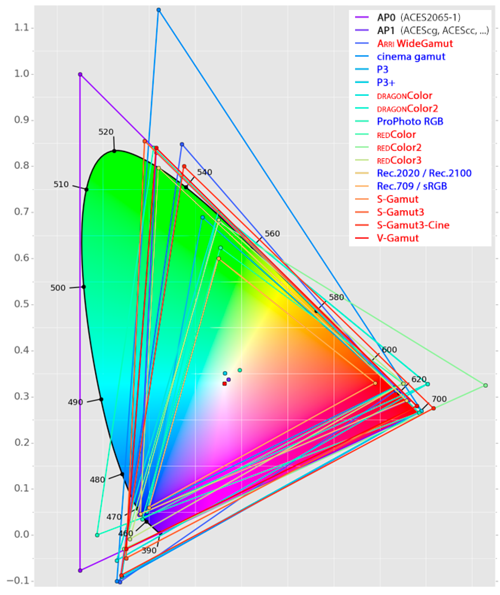
Figure 3.
Toy-model of a simple, single-camera, non-ACES “basic” grading pipeline: the arrow on the right orders the “layer-based” representation of real-time image processing operations, as performed by the color-correction system in the background, while colorist works. Source footage in its camera-native colorimetry (bottom) is creatively modified by color transforms, either coming from the set (Color Decision Lists, cfr. Section 2.4) and applied in-theater (3-way CC’S); then a “viewing LUT” is applied on top to match the colorimetry with the output device’s for viewing (top). A 3D LUT may represent the overall effect of a single primary grade (possibly lacking accuracy [17,20]), and may include the viewing LUT and all color-space conversions (courtesy: Hieronymus Bosch, The Garden of Earthly Delights, c.1495–1505).

Figure 4.
Example of color grading control surfaces: (a,b) The “Blackboard 2” panel connected to the high-end Baselight system via USB and DVI-D, featuring four 6” full-raster displays (800 × 240), 3 trackballs, 14 rotary encoders, 1 jog/shuttle, 220 backlit self-labeled buttons, plus integrated tablet and QWERTY keyboard (courtesy: FilmLight Ltd.); (c) The mid-end “Elements” modular panel, made up of four independent USB controllers featuring overall five 160-character displays, 4 trackballs/jogs, 12 rotaries, 45 buttons; (d) The low-end “Ripple” USB controller: 3 trackballs, 3 rotaries, 8 buttons; (c,d) are compatible with most commercial editing/color grading systems (courtesy: Tangent Wave Ltd.).
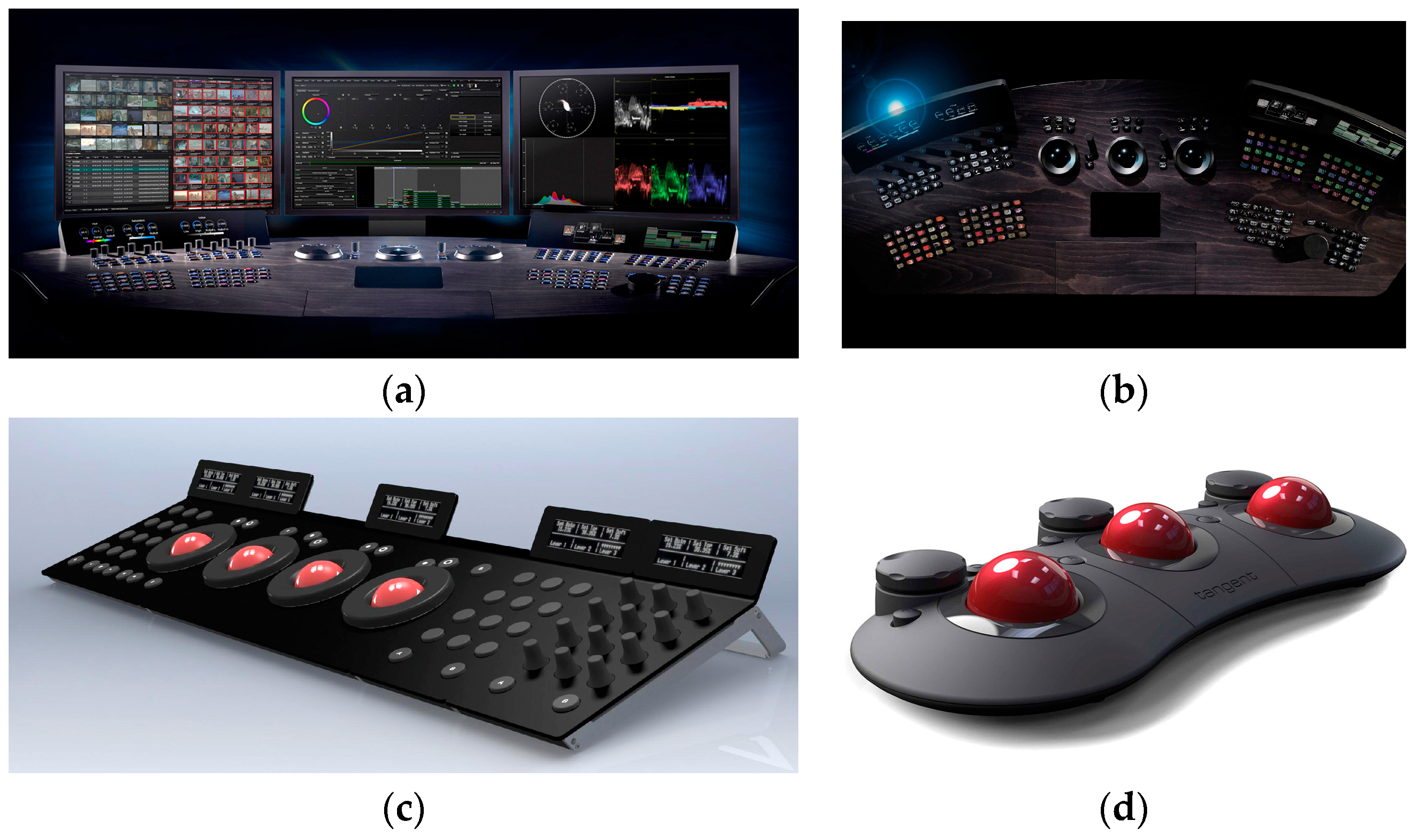
Figure 5.
How ColorLUTs work (in 8 bits/channel color-spaces): (a) concept difference between a 1D LUT (discrete version of a color curve) and a 3D LUT (a discrete vector space [2], i.e., a 3rd-order tensor); (b) a 3D LUT maps a mesh of sampled RGB 3-tuples into target RGB 3-tuples; the other colors are mapped by interpolating points in both the source and target color-spaces (also cfr. Figure 6).

Figure 6.
Vector-field representation of 3D LUTs [20]: source gamut is a regular cubic grid (not shown) whose points are mapped to an (irregular) target gamut. Each sphere in these graphs is a map between two RGB 3-tuples: the sphere’s hue as source and its position as target. (a) Creative “musical” look obtained via mild primary grading; (b) extreme creative look obtained via clipped primary grading; (c) Kodak Vision print film emulation (PFE) to Rec.709; (d) Inverse PFE into a HDR color-space.

Figure 7.
Overall view of an ACES 1.0 end-to-end pipeline; the ACES logotype (Section 3.2) is shown at the top-right corner (courtesy: AMPAS).
Figure 7.
Overall view of an ACES 1.0 end-to-end pipeline; the ACES logotype (Section 3.2) is shown at the top-right corner (courtesy: AMPAS).
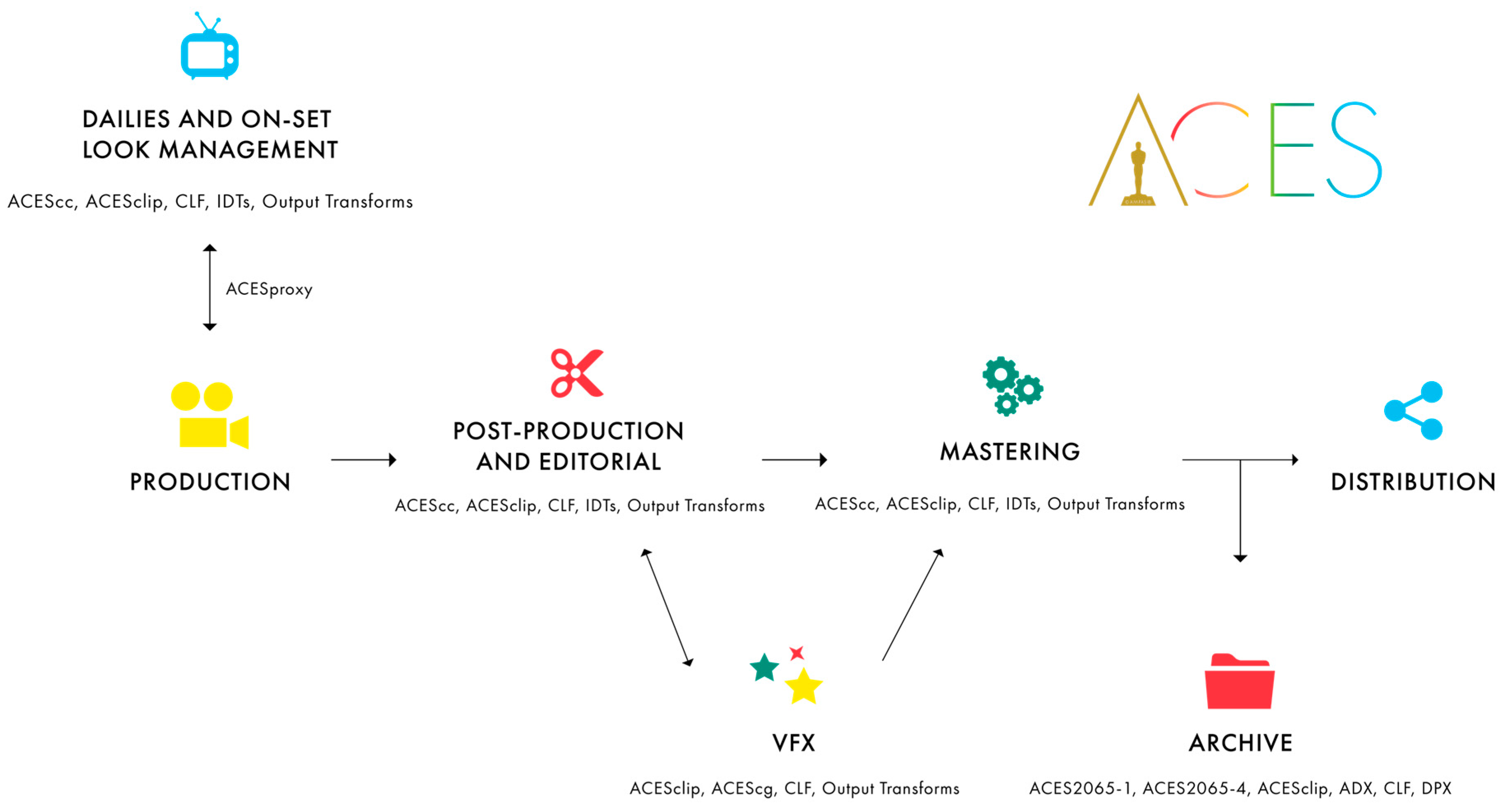
Figure 8.
Comparisons for ACES gamuts: (a) AP0 (purple) vs. AP1 (cyan, yellow-filled); (b–d) Details of several gamuts (AP0, AP1, P3, BT.2100) cross-coverage near the edges of the three color primaries.
Figure 8.
Comparisons for ACES gamuts: (a) AP0 (purple) vs. AP1 (cyan, yellow-filled); (b–d) Details of several gamuts (AP0, AP1, P3, BT.2100) cross-coverage near the edges of the three color primaries.

Figure 9.
ACEScc transfer curve in a “EV/CV plot”, i.e., the log2 of scene exposure relative to 18% grey in abscissa (photometric stops) vs. CV range in ordinate. Compare with: (a) ACEScct; (b) ACESproxy.
Figure 9.
ACEScc transfer curve in a “EV/CV plot”, i.e., the log2 of scene exposure relative to 18% grey in abscissa (photometric stops) vs. CV range in ordinate. Compare with: (a) ACEScct; (b) ACESproxy.

Figure 10.
Schematic of a linear and very simple ACES color pipeline; the black-edged triangles indicate ACES components. Left-to-right: Camera footage enters ACES scene-referred colorimetry via an IDT; creative color decisions are applied as Looks (LMT); final output is carried over through the Output Transform (RRT + ODT) combination, leading to a display-referred colorimetry ready for output to standard output device (a theatrical projector in this case).

Figure 11.
Diagrams showing LMT-based color pipeline samples: (a) “Black-box” LMT as mapping ACES2065-1 CVs ACES into ACES2065-1 CVs ACES′; (b) Empirical LMT including a color-grading operation (set, for example, as a 3D LUT acting within ACEScct color-space); (c) Analytic LMT acting as primary color-correction first (as a CDL in ACEScc), followed by concatenation of hue shifts.

Figure 12.
File-type icon study for ACESclip (.ACESclip.xml extension), sized 512 down to 16 pixels.
Figure 12.
File-type icon study for ACESclip (.ACESclip.xml extension), sized 512 down to 16 pixels.
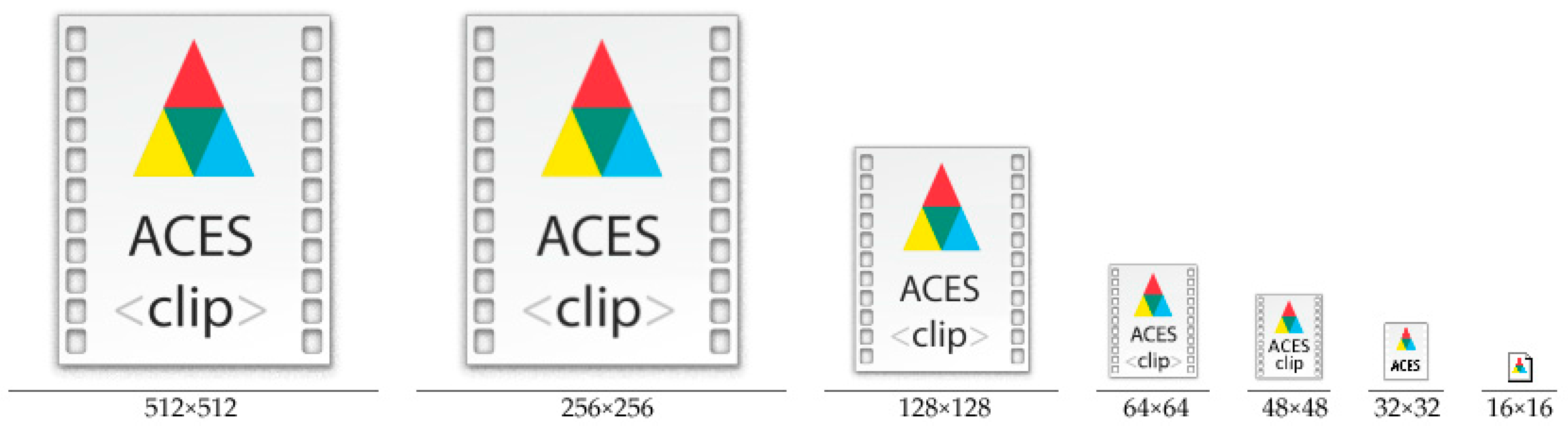
Figure 13.
Comprehensive (yet simple) ACES pipeline involving multiple sources: film scans (Section 3.11), a real digital camera, an ideal RICD (Section 3.4), and multiple deliveries (film + digital projection, SDR + HDR TV, Section 3.6).
Figure 13.
Comprehensive (yet simple) ACES pipeline involving multiple sources: film scans (Section 3.11), a real digital camera, an ideal RICD (Section 3.4), and multiple deliveries (film + digital projection, SDR + HDR TV, Section 3.6).

Figure 14.
Example of creation and use of an empirical LMT from a film workflow (cfr. Section 3.6): after applying a conversion to ADX color-space and concatenating a pre-existing PFE (cfr. Section 3.11 and Figure 6c) from a traditional DI color pipeline (used to mimic a specific film stock into a DCI X′Y′Z′ output colorimetry, cfr. Section 6), a conversion back to ACES2065-1 is done to map to ACES′ CVs. This overall transformation may be burned into another 3D LUT acting as empirical LMT to achieve the same look (ACES′ CVs) for any other footage—including those not from film scans.

Figure 15.
ACES-based color grading (cfr. Figure 3), with the arrow on top ordering this “layer-based” representation of real-time image processing. Source footage in its camera-native colorimetry (left) technically enters the color pipeline by means of Input Transforms (camera A is represented, but different IDTs may be used for cameras B, C, …). After everything is converted in ACES2065-1 CVs, creative grading is done via same operators as in the non-ACES case, i.e., CDLs, 3-way CC’s, creative LUTs (both LMT and secondary grades), with implicit conversion to either ACEScc or ACEScct as working color-space and, after all CC layers, back. Viewing on the reference monitor/projector (right) is done via RRT + ODT (courtesy: Hieronymus Bosch, The Garden of Earthly Delights, c.1495–1505).
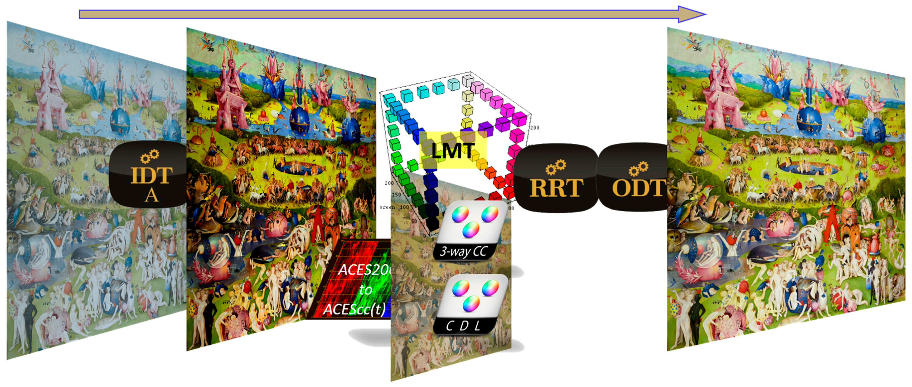
Figure 16.
Camera-department tests: (a) camera-test footage, as processed by on-set equipment (no CDL), with detail zone in red; (b) differences with the same footage and same processing by finishing department (white areas mean the two sources sum to 0). High-frequency discrepancies are evident.
Figure 16.
Camera-department tests: (a) camera-test footage, as processed by on-set equipment (no CDL), with detail zone in red; (b) differences with the same footage and same processing by finishing department (white areas mean the two sources sum to 0). High-frequency discrepancies are evident.

Figure 17.
Node-based graph from The Foundry Nuke’s CGI/VFX comparison project. Read nodes apply the corresponding Input Transforms to footage (if needed, as in this case, for ARRIRAW .ari files). The OCIOCDLTransform nodes interpret CDLs from the XML metadata to compare with versions with baked-in CDLs. Merge nodes composite different images together or compute pixelwise subtraction to verify the consistency. The Truelight node is the Baselight for Nuke plugin when a BLG file is used to transport a scene’s color correction instead of a CDL. The Viewer node is where different viewing paths are sent for application of the Output Transform (RRT+ODT) to compositor’s PC monitor.


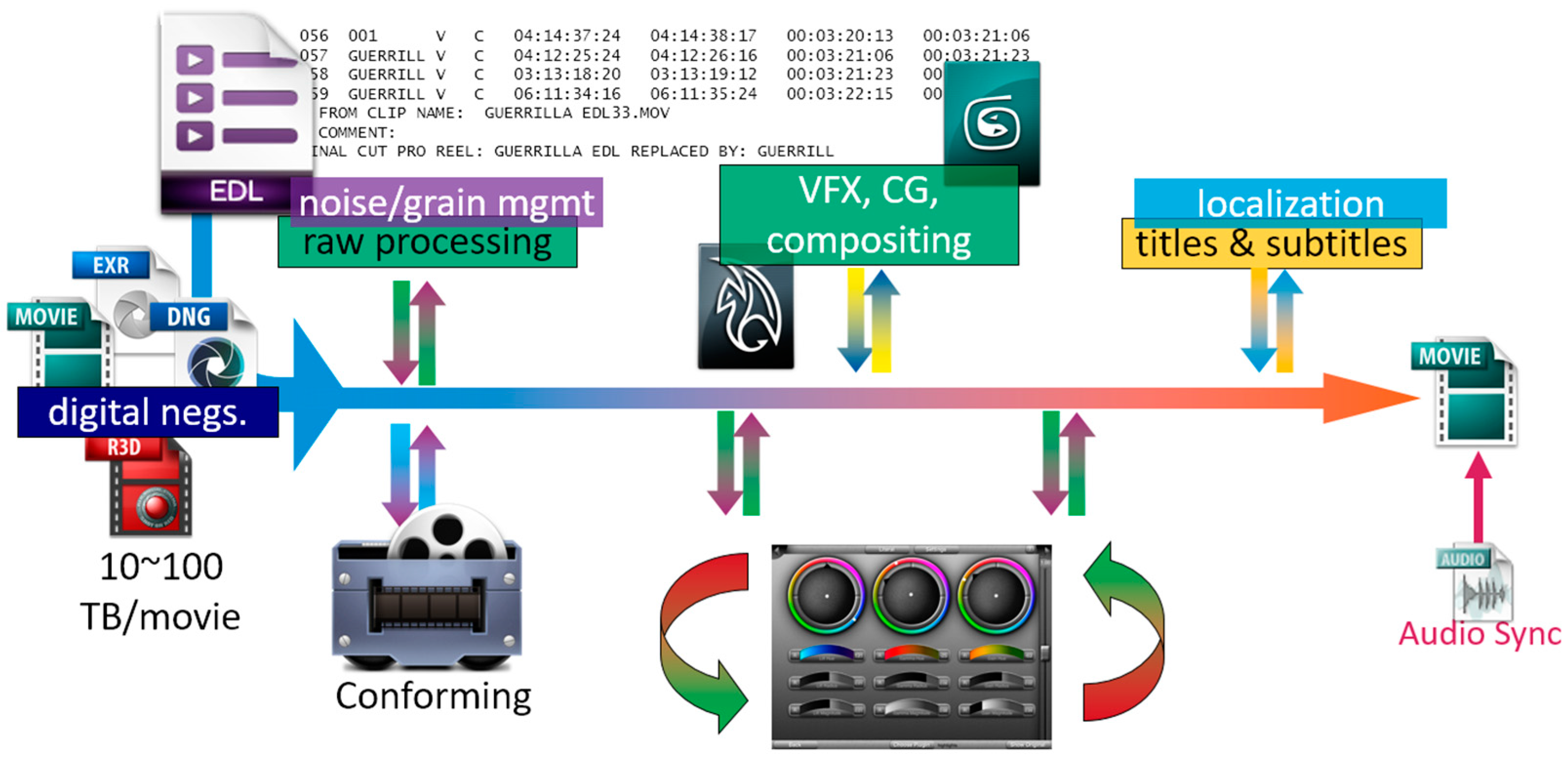
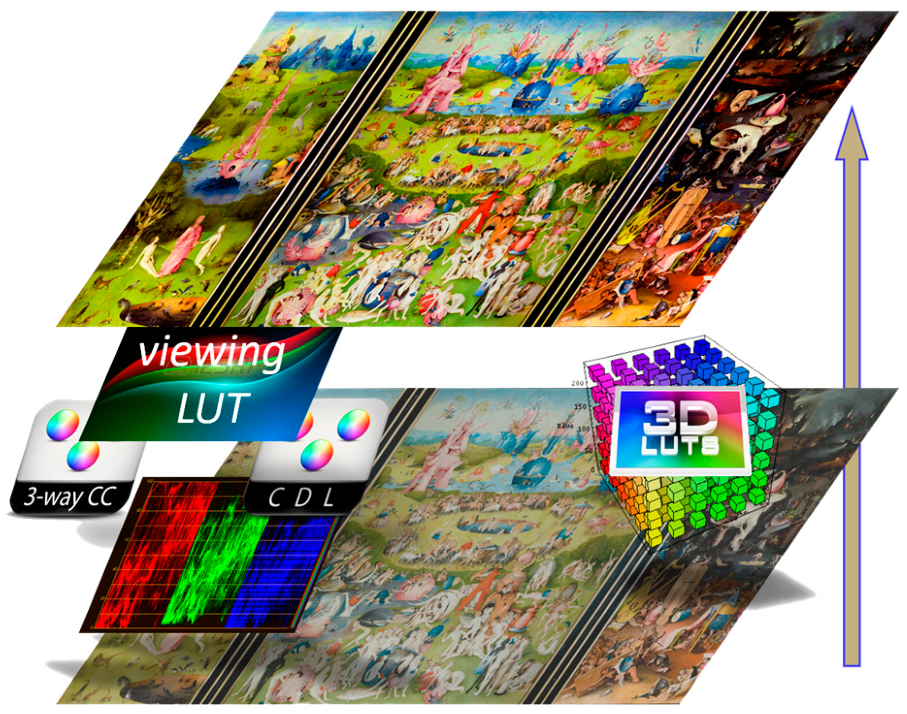
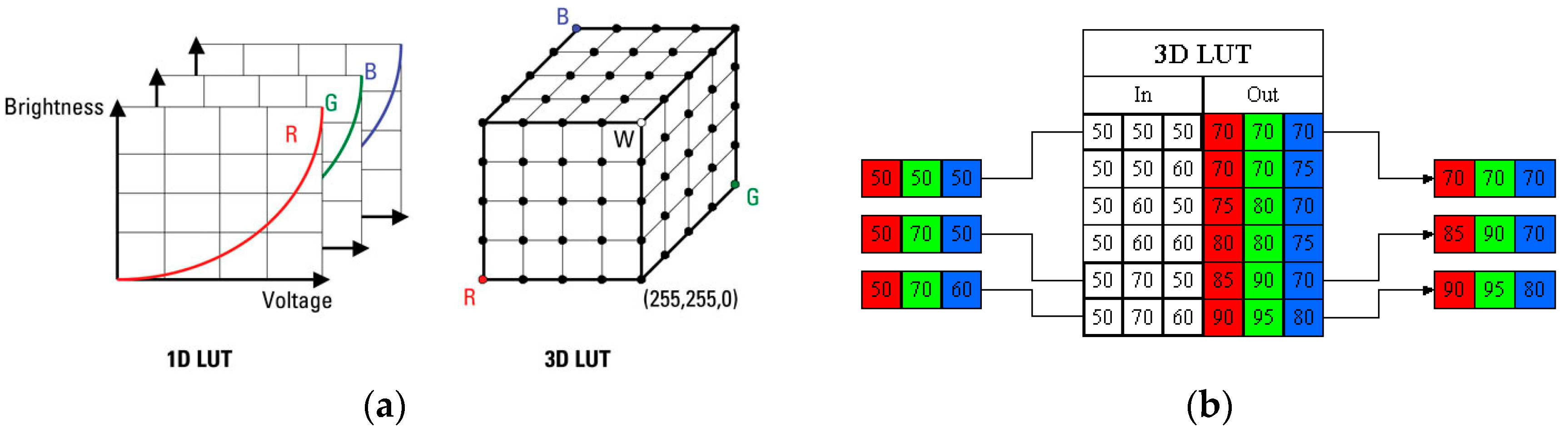
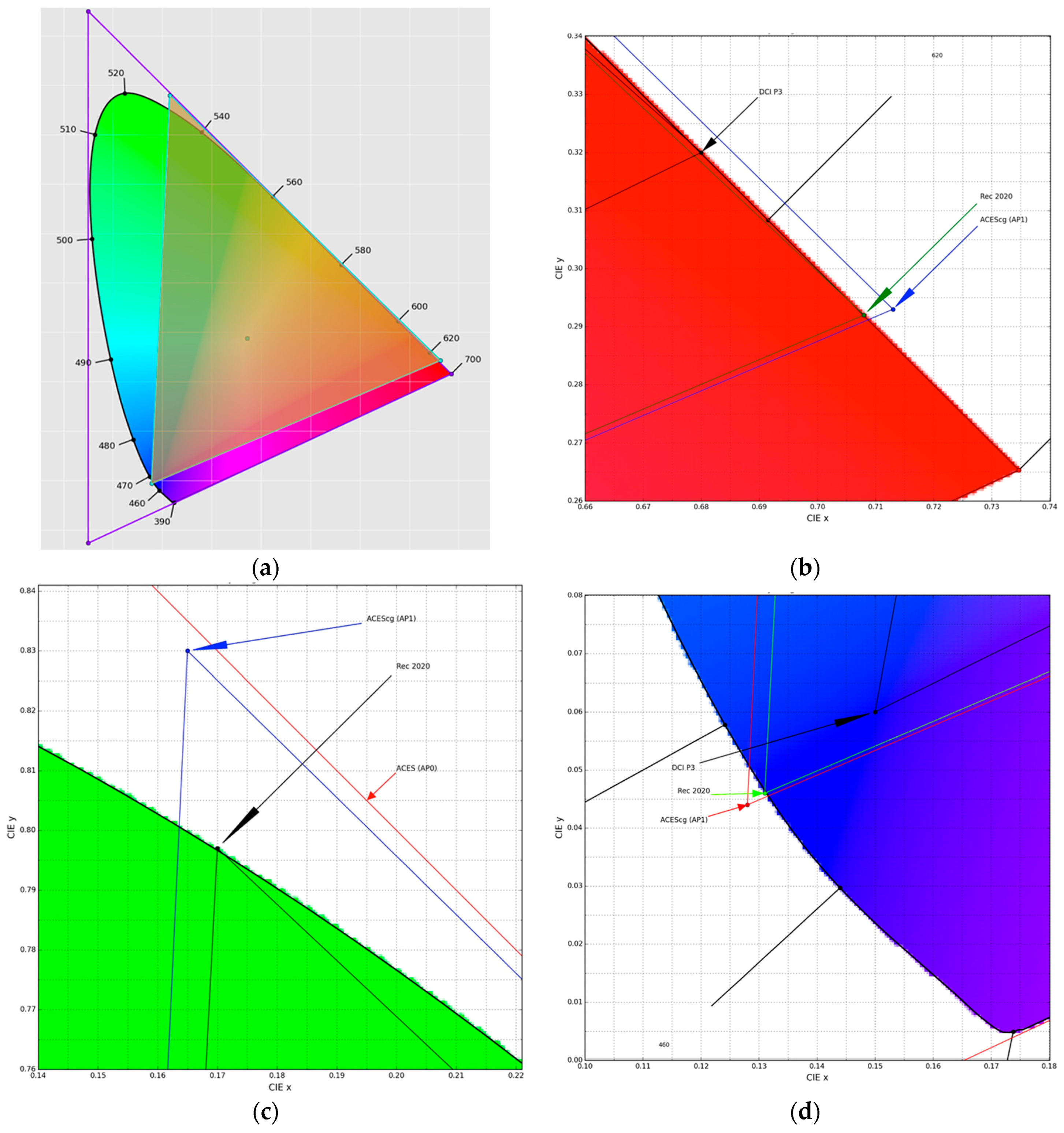
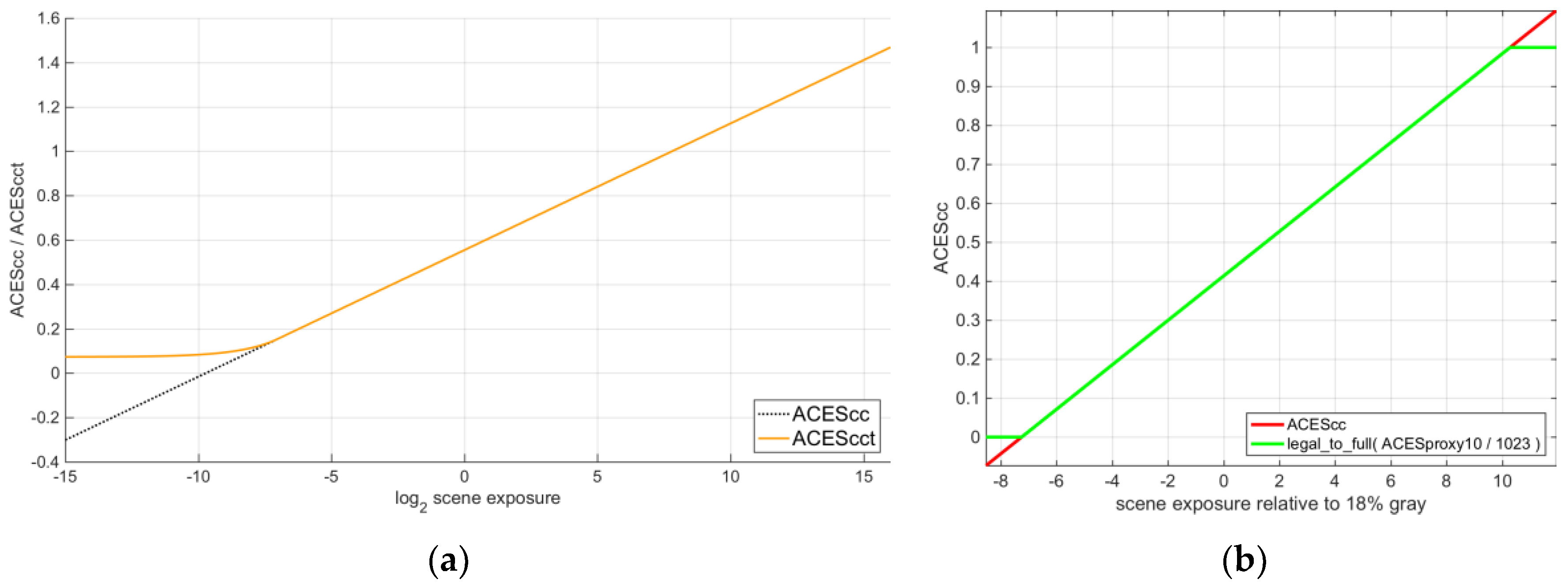
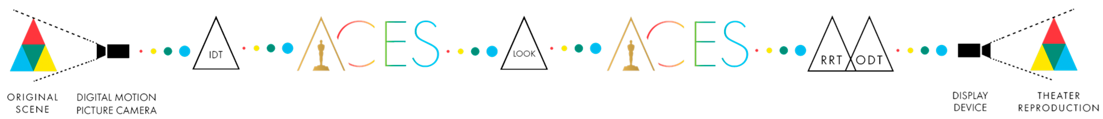
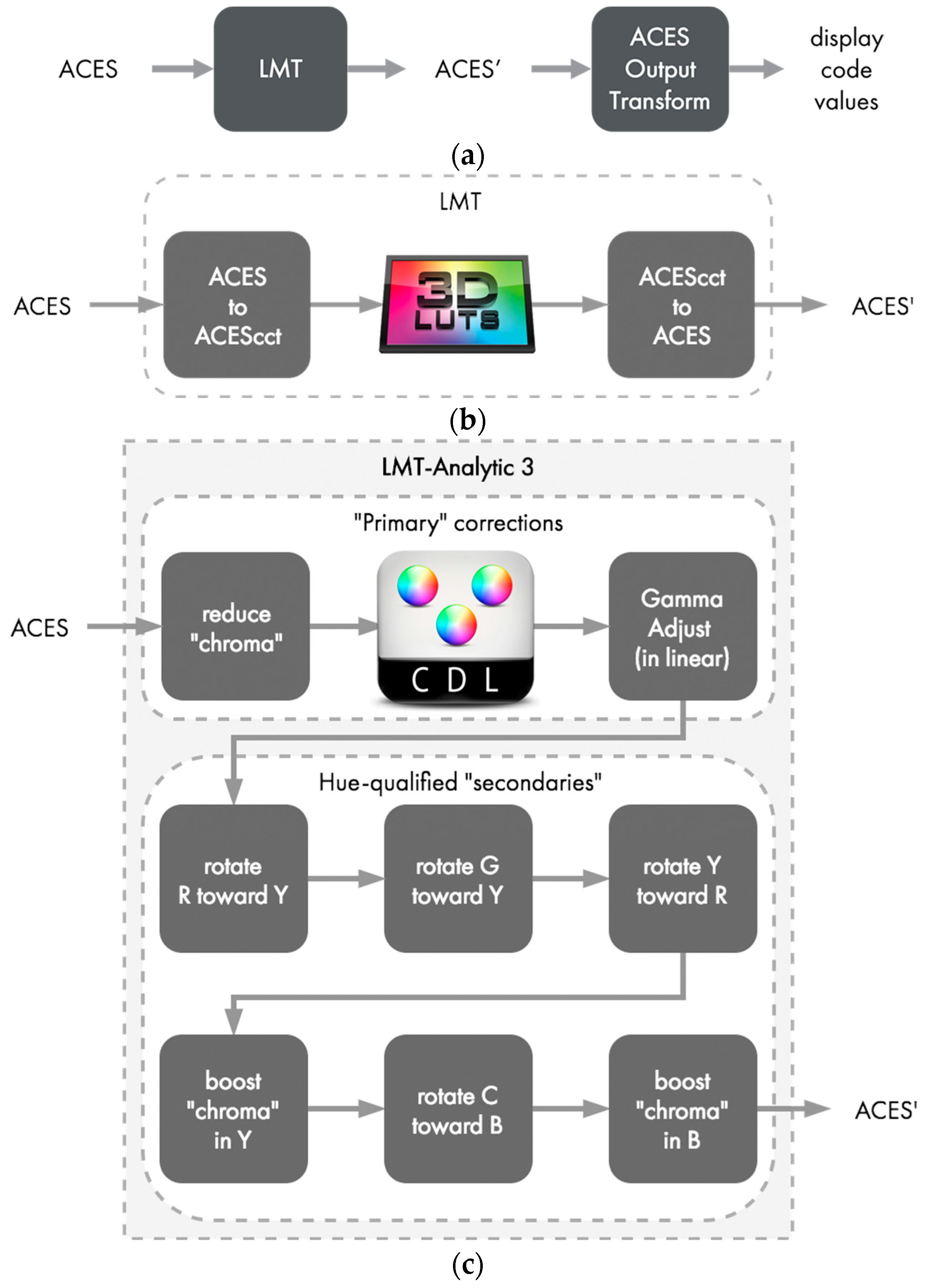
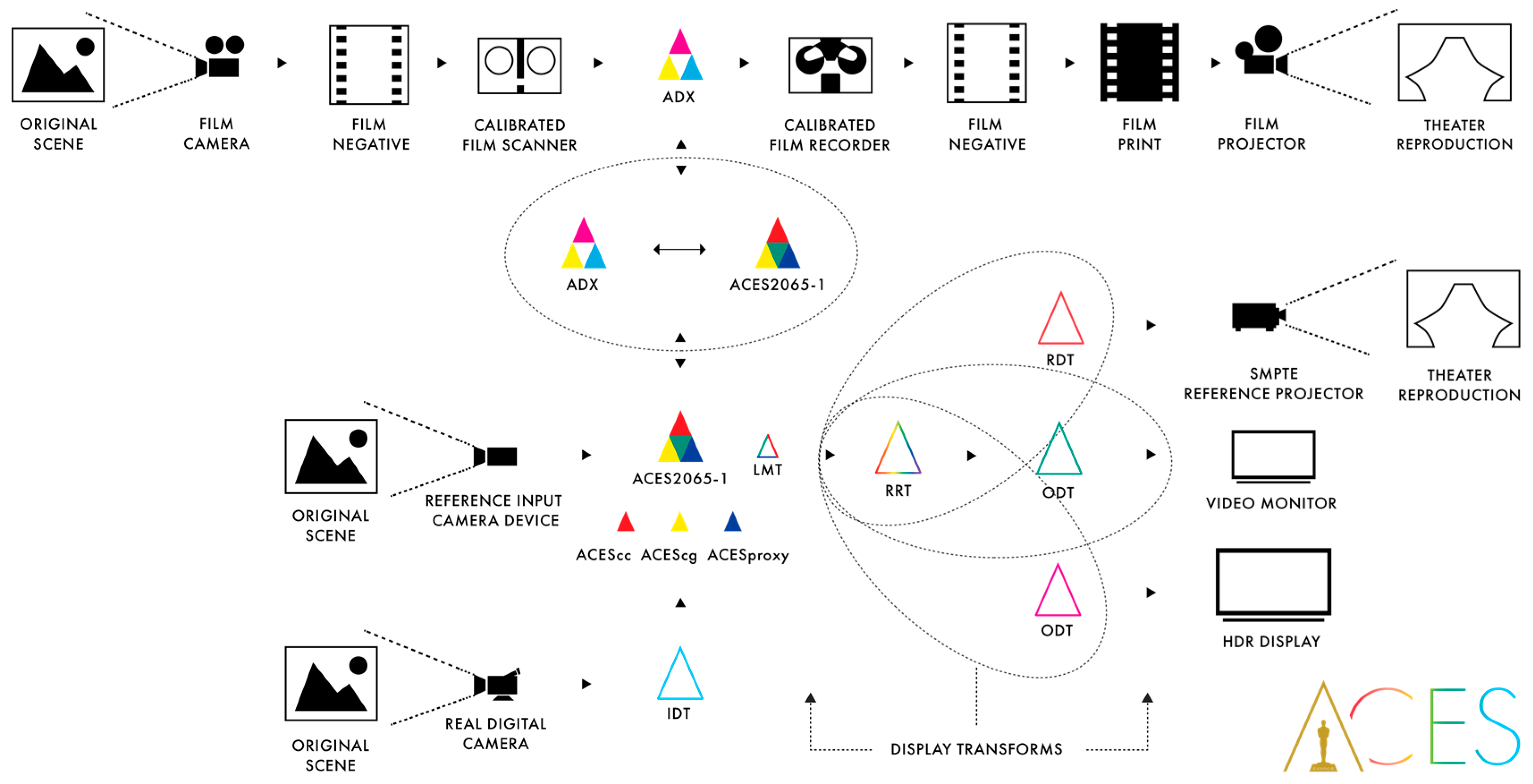
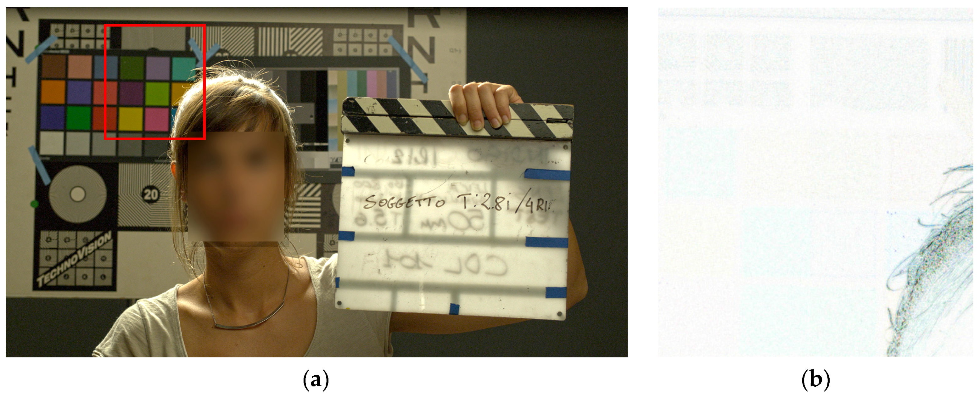
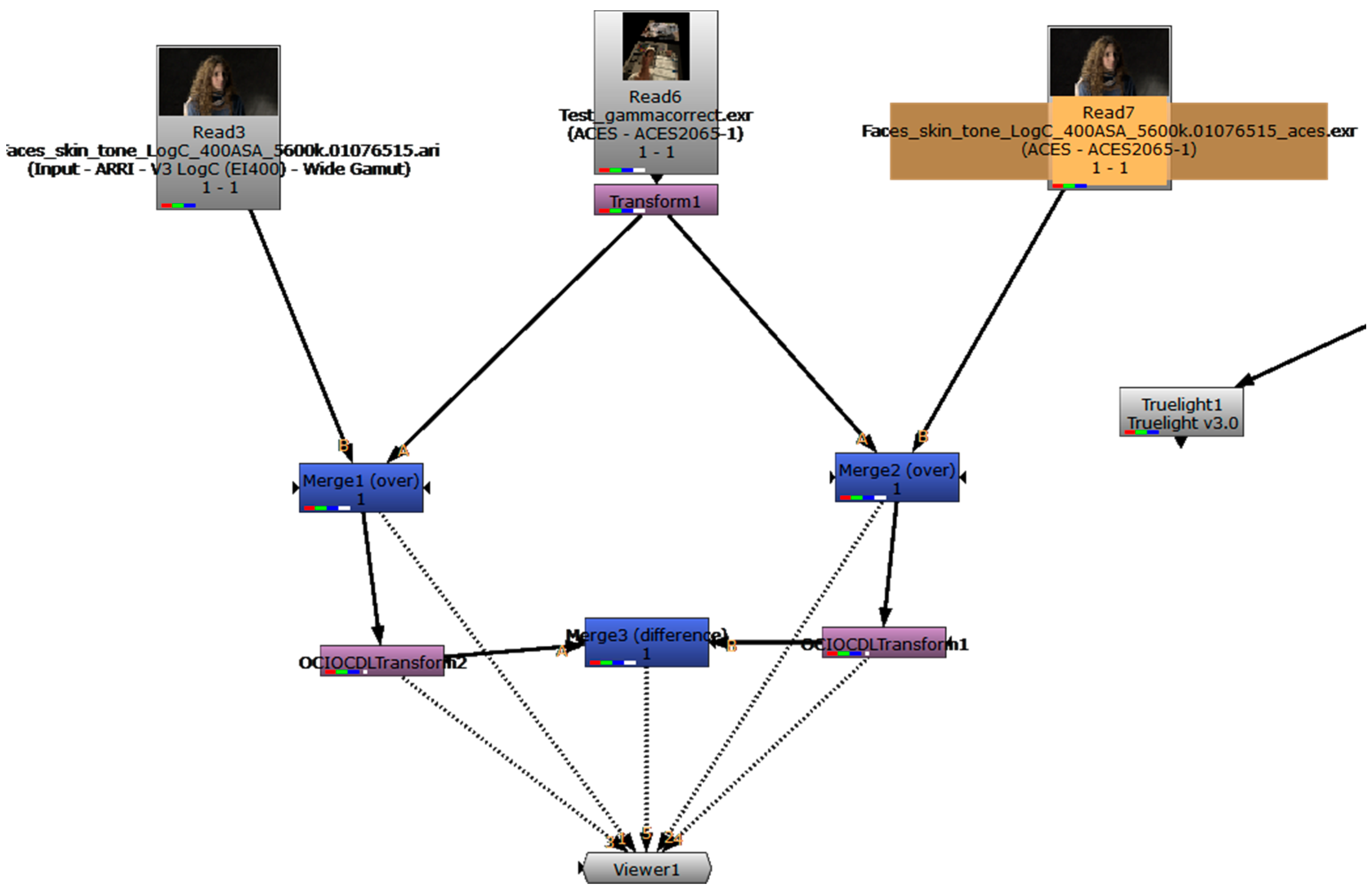
Table 1.
Output colorimetric standards employed officially, or as de-facto, in (2017) media production, arranged according to viewing devices, environments and dynamic ranges; cfr. Table 2.
Table 1.
Output colorimetric standards employed officially, or as de-facto, in (2017) media production, arranged according to viewing devices, environments and dynamic ranges; cfr. Table 2.
| Dynamic Range | PC Monitor | HD TV | Cinema | UltraHD TV |
|---|---|---|---|---|
| SDR | sRGB [24] | BT.709 3 [25] | DCI P3 4 [26] | BT.1886 [27] |
| HDR 1 | ― 2 | BT.2100 3 [28] | ST2084 5 [29] | BT.2020 3 [30] and BT.2100 3 |
Note: 1 There exist many proprietary technologies not completely bound to standards, widely used in broadcast and sold in consumer TV: Dolby®Vision, Hybrid Log-Gamma (HLG), HDR10(+), etc.; 2 Market is pushing for DCI P3; 3 Informally known as Rec.709, Rec.2020 and Rec.2100 respectively; 4 Post labs often use D60 or D65 “creative white-points” instead of DCI’s; 5 Defines “PQ curve” (Dolby®Vision and HDR10) and HLG transfer functions.
Table 2.
CIE (x,y) chromaticity values for the ACES color-spaces’ primaries/white-point, compared with a few known camera and reference-display color-spaces; cfr. Table 1.
Table 2.
CIE (x,y) chromaticity values for the ACES color-spaces’ primaries/white-point, compared with a few known camera and reference-display color-spaces; cfr. Table 1.
| Gamut Name | Red | Green | Blue | White-Point | |||||
|---|---|---|---|---|---|---|---|---|---|
| AP0 | 0.7347 | 0.2653 | 0.0 | 1.0 | 0.0001 | −0.0770 | D60 | 0.32168 | 0.33767 |
| AP1 | 0.7130 | 0.2930 | 0.1650 | 0.8300 | 0.1280 | 0.0440 | D60 | 0.32168 | 0.33767 |
| sRGB/BT.709 | 0.6400 | 0.3200 | 0.3000 | 0.6000 | 0.1500 | 0.0600 | D65 | 0.31270 | 0.32900 |
| ROMM RGB | 0.7347 | 0.2653 | 0.3000 | 0.6000 | 0.0366 | 0.0001 | D50 | 0.34567 | 0.35850 |
| CIE RGB | 0.7347 | 0.2653 | 0.2738 | 0.7174 | 0.1666 | 0.0089 | E | 0.33333 | 0.3333 |
| ARRI W.G. | 0.6840 | 0.3130 | 0.2210 | 0.8480 | 0.0861 | −0.1020 | D65 | 0.31270 | 0.32900 |
| DCI P3 | 0.6800 | 0.3200 | 0.2650 | 0.6900 | 0.1500 | 0.0600 | DCI | 0.31400 | 0.35105 |
| BT.2100/2020 | 0.7080 | 0.2920 | 0.1700 | 0.7970 | 0.1310 | 0.0460 | D65 | 0.31270 | 0.32900 |
Table 3.
Technical characteristics of the six ACES color-spaces.
| ACES2065-1 | ACEScg | ACEScc/ACEScct | ACESproxy | ADX | |
|---|---|---|---|---|---|
| primaries | AP0 | AP1 | AP1 | AP1 | APD |
| white-point | D60 | D60 | D60 | D60 | ~Status-M |
| gamma | 1.0 | 1.0 | |||
| arithmetic | floats 16b | floats 16/32b | floats 16/32b | int. 10/12b | int. 10/16b |
| CV ranges: | Full | Full | Full | SDI-legal | Full |
| legal (IRE) | [−65504.0, 65504.0] | same 1 | [−0.358447,65504.0] 2 | [64, 940] 3 | [0, 65535] 4 |
| ±6.5 EV | [−0.0019887, 16.2917] | same 1 | [0.042584, 0.78459] 2 | [101, 751] | ― 5 |
| 18%, 100% grey | 0.180053711, 1. | same 1 | 0.4135884, 0.5579 | 426, 550 3 | ― 5 |
| Purpose | file interchange; mastering; archival | CGI; compositing | color grading | real-time video transport only | film scans |
| Specification | [1,48,61] | [49] | [50]/[52] | [53] | [54,62,63] |
Note: 1 ACEScg has the same full/legal ranges and 18%-grey/100%-white CVs as ACES2065-1. 2 This is for ACEScc only; ACEScct uses legal range [0.072906, +∞] and ±6.5 EV range [0.093867, 0.78459]. 3 These are 10-bit CVs; The full range/18%-grey/100%-white 12-bit CVs are [256, 3760], 1705 and 2200. 4 This is for the 16-bits variant; the 10-bits has [0, 1023]. 5 ADX has no set CVs for certain EVs.
Table 4.
Technical constrains and mandatory metadata for ST2065-4/5 compliant ACES content.
| OpenEXR (ST2065-4) | MXF (ST2065-5) |
|---|---|
| version/endianness/header: 2.0/little/≤1 MiB | essence container: MXF Generic Container |
| attribute structure: name, type name, size, value | mapping kind: ACES Picture Element |
| tiling: scanlines (↑↓ order), pixel-packed | content kind: Frame- or Clip-wrapped as ST2065-4 |
| bit-depth/compression: 16 bpc floats [73]/none | MXF Operational Pattern(s): any |
| channels: (b,g,r) or (α,b,g,r) or S3D: ([α],b,g,r,[left.α],left.b,left.g,left.r) | content package (frame-wrapped): in-sync and unfragmented items of each system/picture/audio/data/compound type |
| color-space: ACES2065-1 [61] | Image Track File’s top-level file package: RGBA Picture Essence |
| raster/ch./file size: ≤4096 × 3112/ ≤8 / >200 MB | channels: (b,g,r) or (α,b,g,r) |
| Mandatory metadata: acesImageContainerFlag=1, adoptedNeutral, channels, chromaticities, compression=0, dataWindow, displayWindow, lineOrder, pixelAspectRatio, screenWindowCenter, screenWindowWidth (stereoscopic images: multiView) | Mandatory essence descriptors: Frame Layout = 0 = full_frame, Video Line Map = [0,0], Aspect Ratio = abs(displayWindow[0]· pixelAspectRatio)/displayWindpw [1], Transfer Characteristic = RP224, Color Primaries = AP0 [61], Scanning Direction = 0 |
© 2017 by the author. Licensee MDPI, Basel, Switzerland. This article is an open access article distributed under the terms and conditions of the Creative Commons Attribution (CC BY) license (http://creativecommons.org/licenses/by/4.0/).
Share and Cite
MDPI and ACS Style
Arrighetti, W. The Academy Color Encoding System (ACES): A Professional Color-Management Framework for Production, Post-Production and Archival of Still and Motion Pictures. J. Imaging 2017, 3, 40. https://doi.org/10.3390/jimaging3040040
AMA Style
Arrighetti W. The Academy Color Encoding System (ACES): A Professional Color-Management Framework for Production, Post-Production and Archival of Still and Motion Pictures. Journal of Imaging. 2017; 3(4):40. https://doi.org/10.3390/jimaging3040040
Chicago/Turabian StyleArrighetti, Walter. 2017. "The Academy Color Encoding System (ACES): A Professional Color-Management Framework for Production, Post-Production and Archival of Still and Motion Pictures" Journal of Imaging 3, no. 4: 40. https://doi.org/10.3390/jimaging3040040
Note that from the first issue of 2016, this journal uses article numbers instead of page numbers. See further details here.