Neutron Imaging Facilities in a Global Context

Laboratory for Neutron Scattering & Imaging, Paul Scherrer Institute, CH-5232 Villigen, Switzerland
J. Imaging 2017, 3(4), 52; https://doi.org/10.3390/jimaging3040052
Submission received: 30 October 2017
/
Revised: 8 November 2017
/
Accepted: 17 November 2017
/
Published: 21 November 2017
(This article belongs to the Special Issue Neutron Imaging)
Abstract
:Neutron Imaging (NI) has been developed in the last decades from a film-based inspection method for non-destructive observations towards a powerful research tool with many new and competitive methods. The most important technical step forward has been the introduction and optimization of digital imaging detection systems. In this way, direct quantification of the transmission process became possible—the basis for all advanced methods like tomography, phase-contrast imaging and neutron microscopy. Neutron imaging facilities need to be installed at powerful neutron sources (reactors, spallation sources, other accelerator driven systems). High neutron intensity can be used best for either highest spatial, temporal resolution or best image quality. Since the number of such strong sources is decreasing world-wide due to the age of the reactors, the number of NI facilities is limited. There are a few installations with pioneering new concepts and versatile options on the one hand, but also relatively new sources with only limited performance thus far. It will be a challenge to couple the two parts of the community with the aim to install state-of-the-art equipment at the suitable beam ports and develop NI further towards a general research tool. In addition, sources with lower intensity should be equipped with modern installations in order to perform practical work best.
1. Introduction
Shortly after the discovery of the neutron by J. Chadwick in 1932, the first trials were done to use neutron beams for transmission images of test samples. The first radiographies with films are attributed to Kalmann and Kuhn [1,2] who used accelerators and radioactive sources, already with the moderation to thermal neutrons. The breakthrough in neutron radiography was achieved when dedicated beams from a research reactor were used and the exposure time was in the order of minutes only.
Until the mid-1990s of the last century, film methods were dominantly used for special non-destructive testing purposes in industry [3] (turbine blades, explosive initiators, moisture measurements, etc.) and nuclear technology in particular [4] to study fuel elements. Usage in the military sector has not been officially communicated.
The introduction of digital imaging techniques provided many advantages and enabled a much more efficient utilization of the neutron beams. Along with the detectors, new and dedicated imaging facilities were also designed and built at powerful neutron sources [5,6,7,8].
This paper gives the overview about the current situation in the field of neutron imaging with respect to facilities and their instrumentation. Currently we have a set of about 15 installations seen to be “state-of-the-art” but also the large number of facilities with suboptimal layout and performance. This potential should be used in order to develop neutron imaging (NI) towards a routine inspection method and a very suitable research tool for many applications.
The outlook of the paper describes the currently available methodological features and gives a prospect to new installations and potential upgrades in the world-wide context.
2. Neutron Imaging Facility Layout
Despite random beam port selections in the past (“what was just available and not occupied by other—more important—users”), modern imaging stations should be optimized consequently from the initial source until the detector position. The requirements for a professional and useful system are the following:
- Homogeneous (in space) beam of well thermalized or cold neutrons fitting to the sample and detector size; imaging with fast neutrons is practiced in only few cases.
- Collimation in the order of the spatial resolution of the detection system: L/D > 250 as a minimum (L = collimation length; D = inlet aperture).
- Low background from gamma radiation and fast neutrons
- Intensity as high as possible fitting to the shielding performance with options for downgrading by pinholes or collimators
- Options for energy selection and beam limitation
- Enough space at the detector position for samples and experimental infrastructure
- Access control and radiation protection
Most of the NI facilities are reactor based where the lower power limit for practical usage is in the order of about 1 kW. However, there are also neutron sources based on spallation by protons as shown in Table 1. Spallation sources are seen to be the future in neutron research by the option of energy separation in the time-of-flight-mode and because new research reactors projects have opposition in many countries. They all have a modern neutron imaging facility in their portfolio or plans to install one, respectively.
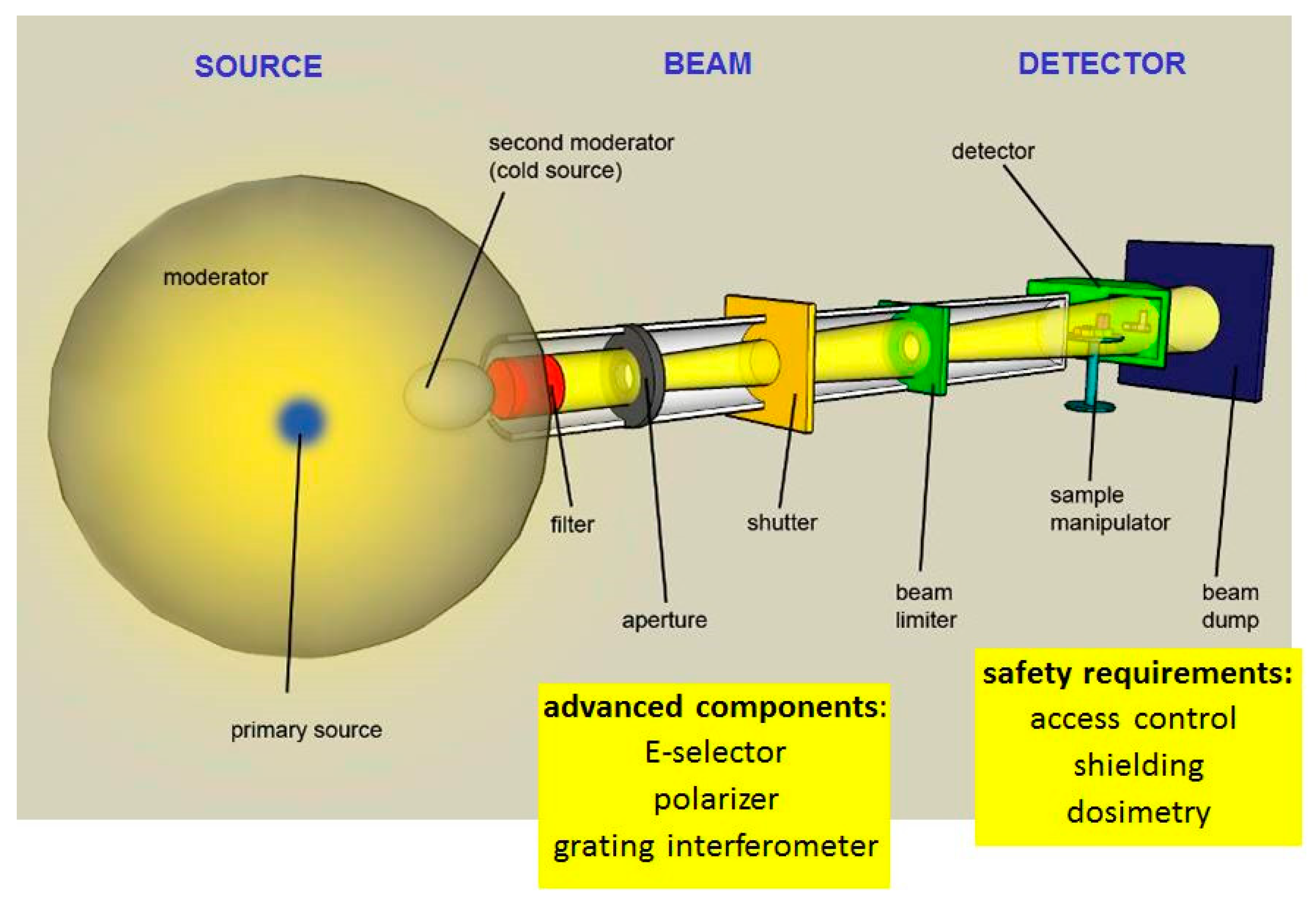
A sketch of a generic NI facility is given in Figure 1 without claim for completeness and scale. Each facility world-wide is unique and has its “personal” layout and performance. However, it is possible to compare parameters like beam intensity, beam size, spectral distribution, collimation and beam quality.
2.1. Detection Systems
In order to substitute the previously common film methods, several developments were initiated at the end of last century. Based on the scintillation driven by neutron capture products (e.g., in Li-6, B-10 or Gd) light sensitive detectors enabled the pixel-wise registration of the neutron beam behind the sample as a “shadow image”. Due to the digital output of the sensors, even unequal distributions of the beam and of the neutron converter can be tolerated and corrected. In this manner, the new detection systems enable a high degree of quantitative correctness also due to their full linear response.
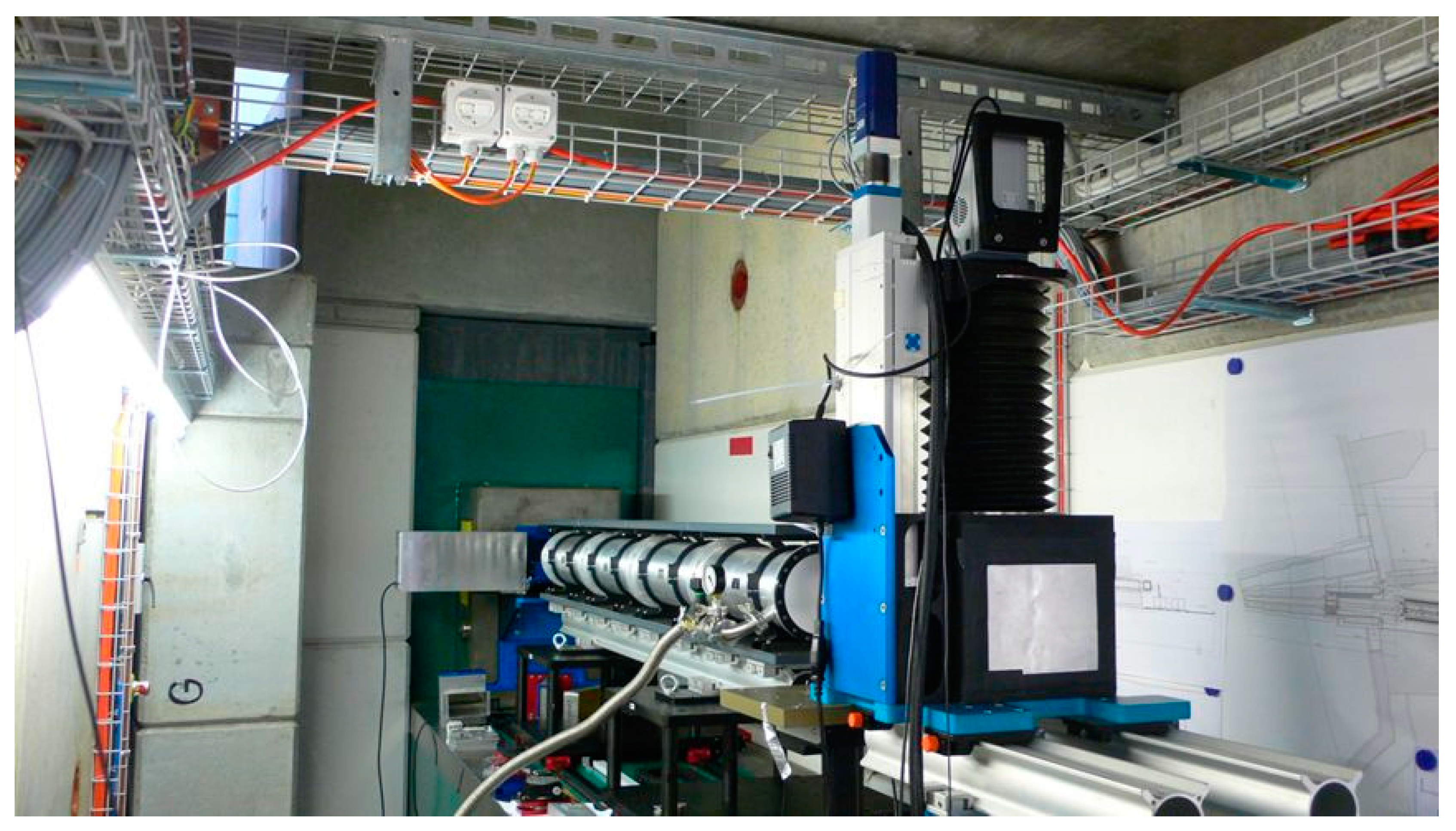
The most flexible and therefore most common setup of a digital detection system is based on camera-scintillator combinations, where the CCD or CMOS camera technology is used. The emission spectrum of the scintillator should fit best to the spectral response of the sensor, which has been achieved in dedicated installations with nearly 100% quantum efficiency. The prototype of the PSI’s MIDI (medium size) setup is shown in Figure 2 as a template. Both scintillators and cameras have been optimized and exposures within less than seconds are common, depending on the beam intensity and the achieved image quality.
The Figure 3 shows the range of the field-of-view (FOV) in logarithmic scale where camera systems can be applied together with the corresponding pixel size since the number of pixels is given by the camera sensor.
Other digital NI detectors are imaging plates doped with Gd or Dy, where the pixel size is defined by the read-out scanner (25–100 µm), amorphous silicon flat panels in combination with a neutron sensitive scintillation screen and other pixelated systems using directly the excitation of charge in the semiconductor material caused from the neutron capture process in a converter material [11].
Time sequences of up to 100 Hz are possible. Using stroboscopic setup repetitive processes can be observed with about 10,000 rpm while multiple projection of one sample during rotation enables the current method of neutron tomography on a routine level.
The application of NI at pulsed sources in the time-of-flight (TOF) mode for the neutron energy selection requires specific new detection systems as given in [12]. The current limitation in the pixel number and the FOV will be overcome by further development and upscaling. Micro-channel-plates (MCP) and fast readout chips are the key components in this development.
2.2. Facility Components
Beside the detection system, components for beam tuning, sample manipulation and protection are necessary. As shown in Figure 1, the initially fast neutrons have to be moderated, filtered and selected in a suitable manner. Since neutrons have no charge, the options for guiding are quite limited. Mirrors or single crystals often degrade the distribution by increasing the divergence and lowering the homogeneity of the beam. Therefore, a simple selection process from a strong source without perturbation is the very best for highest image quality.
Suitable shielding including a safe access system is required for high performance facilities which are in user operation mode. Depending on the beam intensity, the amount of shielding can be quite expensive and requires free space around the beam line [6].
More sophisticated components, mainly in use for neutron physics research projects, are energy selectors (turbine or double-crystal based), choppers, grating interferometers, polarizers and focusing guides. Several beam lines are equipped with specific infra-structure for the sample treatment, such as climate chambers, cryo-magnets, electro-chemistry hardware or pressure cells.
2.3. Beam Properties
Thermal and cold neutrons are preferred for NI studies due to the high attenuation in a high variety for materials and even isotopes; they have the advantage of high penetration through heavy elements while providing a high contrast for light materials. It has to be mentioned that the dominating attenuation process (beside in strong neutron absorbers like B-10, Cd, Gd, etc.) is neutron scattering. Mostly, the scattered neutrons are considered as “lost” and the total cross-sections can be used for quantification. If scattered neutrons can return into the region of the sample’s shadow, some correction will be necessary for a precise quantification [13].
Scattering in crystalline materials is strongly enhanced for cold neutrons, as shown in Figure 4. Depending on the crystal orientation and the lattice parameters, scattering happens until the limit given by Bragg’s law. Narrowing the energy band of the neutron spectrum allows the study of the crystaline structure on the macroscopic scale [14].
2.4. Manpower and Qulification
To build and to operate NI facilities requires educated manpower-physicists, engineers and also technicians. A major difference to the previously used film technology is the high demand in image processing with advanced tools like those used for neutron tomography (reconstruction and visualization), real-time imaging, grating interferometry and all kinds of quantification. Because common facility users are often unable to perform the highly demanding evaluation themselves, strong support has to be given by the operator’s team to guarantee highest possible output from the measurements. At least two scientists and one technician/engineer are needed to operate a high performing beam line professionally and efficiently, supported by PhD students for the improvement of the technology and to enable high scientific output.
3. Research Reactor Data Base (RR DB)
Because most installations for NI are still located at research reactors, the RR DB [15] is a very useful and competent tool for the description of the current situation in the field. The data are based on self-declarations by the facility operators, aided by the knowledge of experts from the International Atomic Energy Agency (IAEA). In addition, the data in Table 1 can be used to complete the picture with respect to NI facilities. There are only a few NI facilities at other accelerator driven neutron sources as yet.
3.1. Overview about Operational Research Reactors
The RR DB enables summary reports about the current status of all registered facilities world-wide and structures in “developed” and “developing countries” separately. In Table 2, such an overview is given where the most important number is cited as “217 operational”.
In order to find out which reactor is useful for NI in principle, it is important to look to the power of the sources. As explained above, the lower power limit of 1 kW is given to make the methods practical for the users. We will find this split in Table 3, where 136 = 38 + 68 reactors seem to be in this power range.
In addition, there are still reactors under construction and planned (mainly in developing countries) while the utilization rate is only high for 42 installations. This describes the high potential for further NI facilities in the world-wide context. It is also very interesting how the 217 reactors are distributed in the different geographical regions. This picture is given by Figure 5. Surprisingly, Eastern European countries host the majority of RRs. However, the numbers of installations do not necessarily correspond to the performance and quality of the beam lines. On the other hand, the number of aged reactors (see Table 3) is quite high with a shutdown risk in the near future.
3.2. Research Reactors Utilization
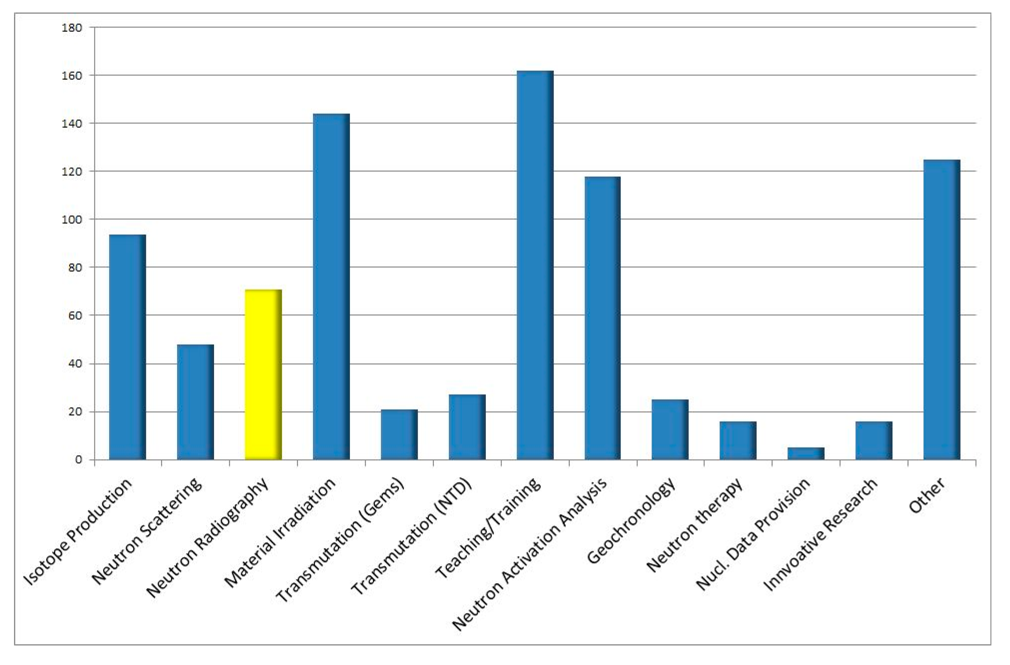
A more complete picture about the situation with respect to their utilization can be derived by the declaration of the operators as given in Figure 5. In this framework, it is quite remarkable and also surprising that “neutron radiography” is declared to be applied in 71 cases, more than “neutron scattering” in only 41 cases. For comparison: as a scientific analytical tool, neutron activation analysis (NAA) is available at 118 facilities (see the data in Figure 6).
Other applications like isotope production, material irradiation and training are very pragmatic options, mainly driven by medical applications and by the nuclear industry.
It can be stated that the potential for NI is given, but some details below will demonstrate that the quality in the layout and in the equipment make the difference between “advanced NI facilities” for research purposes and the older common radiography installations. Unfortunately, there is not much communication among the facility operators and the established network in NI: the International Society for Neutron Radiology (ISNR).
4. ISNR
This society was created in 1996 in Berlin during the 5th World Conference on Neutron Radiography. The main aim has been to have a world-wide platform to exchange the latest knowledge in the field of imaging with neutrons, in particular during “World Conferences (WCNR)” and “International Topical Meetings (ITMNR)”. ISNR has currently 323 members from 41 different countries and can be considered to be the largest community dealing with neutron imaging and its application. The latest information is provided by the homepage of the society [16].
During the latest meetings, in particular the WCNR-10 in Grindelwald (CH) [17] and the ITMNR-8 in Beijing (China) [18], a clear picture came out about the currently most advanced and valuable installations for NI in the world. They are summarized in Table 4 with some technical details. More information is given on the ISNR homepage or on individual sites of the facilities. If the 17 beamlines are reduced by the four at spallation sources, the 13 remaining reactor based ones (some on standby mode) are in clear contrast to the 71 claims in the RR DB list above.
This indicated on the one side that “neutron radiography” is still practiced with old-fashioned technologies, not competitive with the facilities in Table 4.
On the other hand, there is a huge potential for upgrades of under-utilized facilities by setting up useful imaging devices and by initiating a dedicated user program. There is also a high need for communication among the facility operators about best usage of their beam lines. Even if the neutrons are delivered “for free” their usage is highly desired—there is a lack of obvious neutrons in the future due to shutting down on the one side and missing new sources on the other side.
There are initiatives for compact and high-brilliance sources in several countries, based on upgraded older accelerator driven sources or using new and dedicated concepts [19,20]. Fortunately, neutron imaging capabilities are now taken into account from the beginning, with facilities fitting perfectly to the source properties.
5. Methodical Options and Development
Compared to the initial neutron radiography approach with film based methods where the transmission image is fixed with respect to dynamic range, pixel size and contrast, the new digital systems provide much more flexibility and enable new methodological developments.
Using the short exposure time per image, processes can be followed faster than in real-time (defined as 25 Hz–visible video sequences) or in stroboscopic mode, and individual sequence spots of micro-seconds each can be recorded. The observation of objects from different projections enabled the field of neutron tomography to render the whole 3D volume with the precision of the detection system (see Figure 3).
With the help of the selection of individual neutron energy bands, scattering phenomena in poly-crystalline materials become visible on the macroscopic scale. In particular, regarding the new pulsed sources, we will have the best flexibility to tune the beam properties for these kinds of studies. Using the component of the diffracted neutrons by means of a second set of neutron detectors the combination between the transmission and scattering can be combined as “diffractive imaging”.
Neutron grating interferometry [21] opens for a new range of neutron science by the direct study of phase contrasts and the small-angle scattering driven “dark-field imaging”. Even magnetic domain structures become visible in the bulk of materials [22].
The use of polarized neutrons in NI is a new trend which is technically more demanding but enables us to directly visualize magnetic field distributions in free space and in the magnetic materials.
The direct and pixel/voxel-wise comparison of image data from neutron and X-ray setups unified in one single facility is the experimental basis of “data fusion” which can be applied on the different length scales.
6. Conclusions and Outlook
Based on the methodological and instrumental progress mentioned above, some new projects and upgrades are on the way to being realized. Without claim of completeness such initiatives are summarized in Table 5. The status of the projects is quite different, as it the time of completion. However, it is obvious that new sources like in Argentina or Jordan consider a NI facility as “day one” installations while the ILL in Grenoble goes this way now after 50 years of its operation (an earlier attempt failed to attract a real user community).
Therefore, it can be stated that NI has become a routine method in many scientific fields and a powerful tool for industrial applications. Based on the experiences at the advanced facilities, new efficient and user-friendly installations can now be built.
Acknowledgments
This overview was only being possible by the open communication within the NI community and the professional work of the Neutron Imaging & Activation Group (NIAG) at Paul Scherrer Institut, Switzerland.
Conflicts of Interest
The author declares no conflict of interest.
References
- Kallmann, H. Neutron radiography. Research 1947, 1, 254–260. [Google Scholar] [CrossRef]
- Peter, O. Neutronen-Durchleuchtung. Z. Naturforschung 1946, 1, 557–559. [Google Scholar]
- Hawkesworth, M.R.; Walker, J. Review: Radiography with Neutrons. J. Mater. Sci. 1969, 4, 817–835. [Google Scholar] [CrossRef]
- Domanus, J.C. Research and Standardization Activities of the Euratom. Neutron Radiography Working Group; RISØ-M-2524; Risø National Laboratory: Roskilde, Denmark, 1985. [Google Scholar]
- Parameters. Available online: https://www.psi.ch/sinq/neutra/parameters (accessed on 21 November 2017).
- Cold Neutron Radiography and Tomography Facility. Available online: http://www.mlz-garching.de/antares (accessed on 21 November 2017).
- Kardjilov, N.; Hilger, A.; Manke, I.; Strobl, M.; Dawson, M.; Williams, S.; Banhart, J. Neutron tomography instrument CONRAD at HZB. Nucl. Instrum. Methods Phys. Res. Sect. A Accel. Spectrom. Detect. Assoc. Equip. 2011, 651, 47–52. [Google Scholar] [CrossRef]
- Neutron Imaging Facility. Available online: https://physics.nist.gov/MajResFac/NIF/facility.html (accessed on 21 November 2017).
- Morgano, M.; Peetermans, S.; Lehmann, E.H.; Panzner, T.; Filges, U. Neutron imaging options at the BOA beamline at Paul Scherrer Institut. Nucl. Instrum. Methods Phys. Res. Sect. A Accel. Spectrom. Detect. Assoc. Equip. 2014, 754, 46–56. [Google Scholar] [CrossRef]
- TOMCAT-X02DA: Tomographic Microscopy. Available online: https://www.psi.ch/sls/tomcat/tomcat (accessed on 21 November 2017).
- Lehmann, E.H.; Tremsin, A.; Grünzweig, C.; Johnson, I.; Boillat, P.; Josic, L. Neutron imaging—Detector options in progress. J. Instrum. 2011, 6, C01050. [Google Scholar] [CrossRef]
- Tremsin, A.S.; Vallerga, J.V.; McPhate, J.B.; Siegmund, O.H.W. Optimization of Timepix count rate capabilities for the applications with a periodic input signal. J. Instrum. 2014, 9, C05026. [Google Scholar] [CrossRef]
- Hassanein, R.; Lehmann, E.; Vontobel, P. Methods of scattering corrections for quantitative neutron radiography. Nucl. Instrum. Methods Phys. Res. Sect. A Accel. Spectrom. Detect. Assoc. Equip. 2005, 542, 353–360. [Google Scholar] [CrossRef]
- Kockelmann, W.; Frei, G.; Lehmann, E.H.; Vontobel, P.; Santisteban, J.R. Energy selective neutron transmission imaging at a pulsed source. Nucl. Instrum. Methods Phys. Res. Sect. A Accel. Spectrom. Detect. Assoc. Equip. 2007, 578, 421–434. [Google Scholar] [CrossRef]
- Research Reactor Data Base. Available online: https://nucleus.iaea.org/RRDB/RR/ (accessed on 21 November 2017).
- MuhRec—A Tool Suite for CT Reconstruction and Data Processing/Analysis for Neutron Imaging. Available online: http://www.isnr.de/ (accessed on 21 November 2017).
- WCNR10. 10th World Conference on Neutron Radiofraphy, Grindelwald, Switzerland, 5–10 October 2014. Available online: http://www.psi.ch/wcnr10 (accessed on 21 November 2017).
- ITMNR-8. 8th International Topical Meeting on Neutron Radiography (ITMNR-8), Beijing, China, 4–8 September 2016. Available online: https://www.isnr.de/index.php/information/events/itmnr/itmnr-8 (accessed on 21 November 2017).
- High Brilliance Neutron Source. Available online: http://www.fz-juelich.de/jcns/EN/Leistungen/High-Brilliance-Neutron-Source/_node.html (accessed on 21 November 2017).
- Union for Compact Accelerator-driven Neutron Sources (UCANS). Available online: http://www.ucans.org/ (accessed on 21 November 2017).
- Pfeiffer, F.; Grünzweig, C.; Bunk, O.; Frei, G.; Lehmann, E.; David, C. Neutron Phase Imaging and Tomography. Phys. Rev. Lett. 2006, 96, 215505, Erratum in Phys. Rev. Lett. 2006, 97, 069905. [Google Scholar] [CrossRef] [PubMed]
- Grünzweig, C.; David, C.; Bunk, O.; Kohlbrecher, J.; Lehmann, E.; Lai, Y.W.; Schäfer, R.; Roth, S.; Lejcek, P.; Kopecek, J.; et al. Visualizing the propagation of volume magnetization in bulk ferromagnetic materials by neutron grating interferometry. J. Appl. Phys. 2010, 107, 09D308. [Google Scholar] [CrossRef]
Figure 1.
Components of a generic NI facility (not to scale).

Figure 2.
The camera based detection system MIDI (medium size) for samples up to 15 cm, here installed at the BOA test beam line [9] of the Swiss spallation neutron source SINQ.
Figure 2.
The camera based detection system MIDI (medium size) for samples up to 15 cm, here installed at the BOA test beam line [9] of the Swiss spallation neutron source SINQ.

Figure 3.
Working areas of camera based detection systems with respect to field-of-view (FOV) and pixel size (the logarithmic scale needs to be considered); corresponding conditions at the synchrotron beam line TOMCAT [10] are added for comparison; MAXI (up to 40 cm); MIDI (up to 15 cm); MICRO (fixed to 27 mm FOV); n-Microscope (5–10 mm FOV).
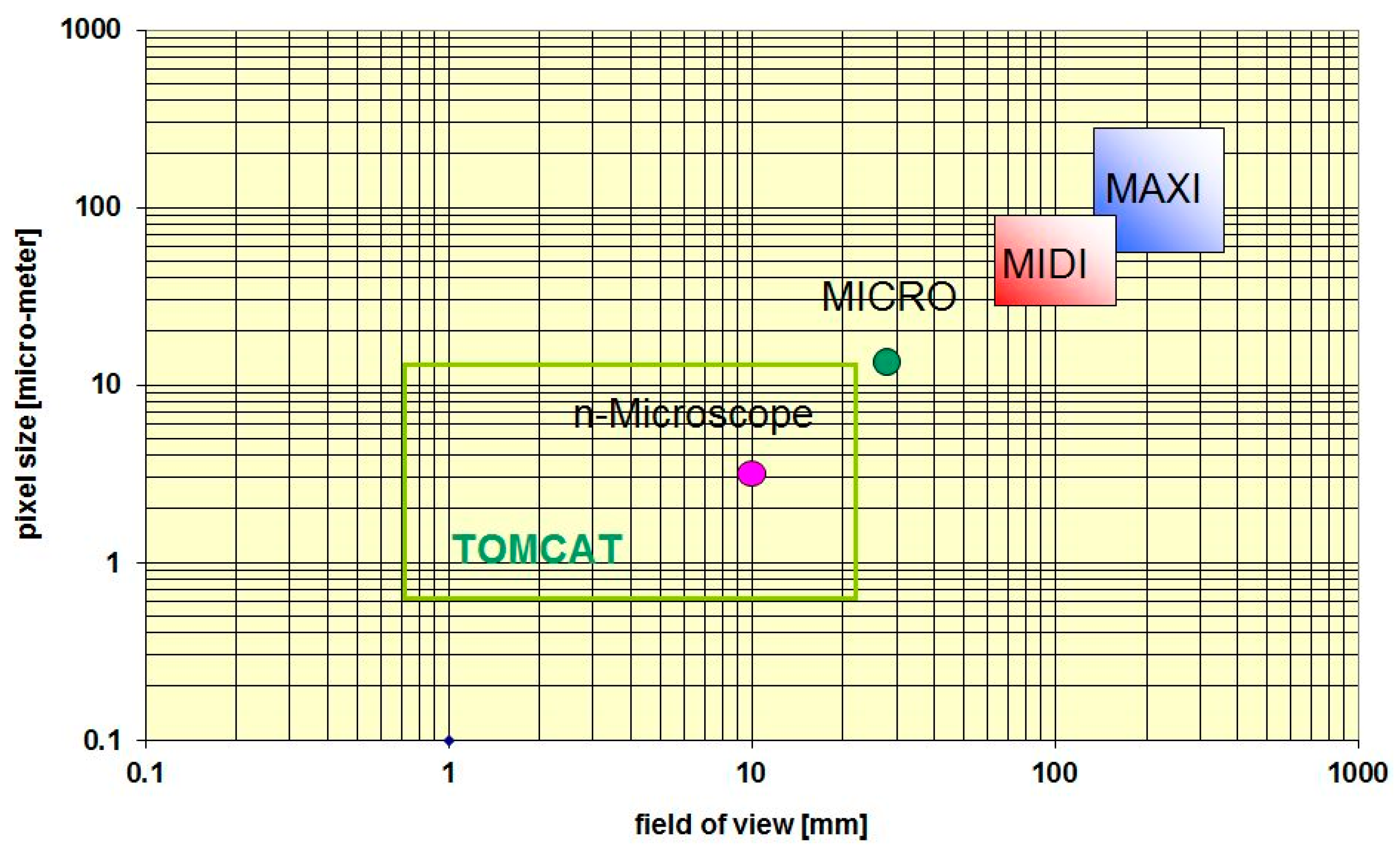
Figure 4.
Options to use energy selective imaging near the Bragg edges of iron; there is mainly absorption above 4 Å while elastic scattering is not relevant for quantification anymore.
Figure 4.
Options to use energy selective imaging near the Bragg edges of iron; there is mainly absorption above 4 Å while elastic scattering is not relevant for quantification anymore.
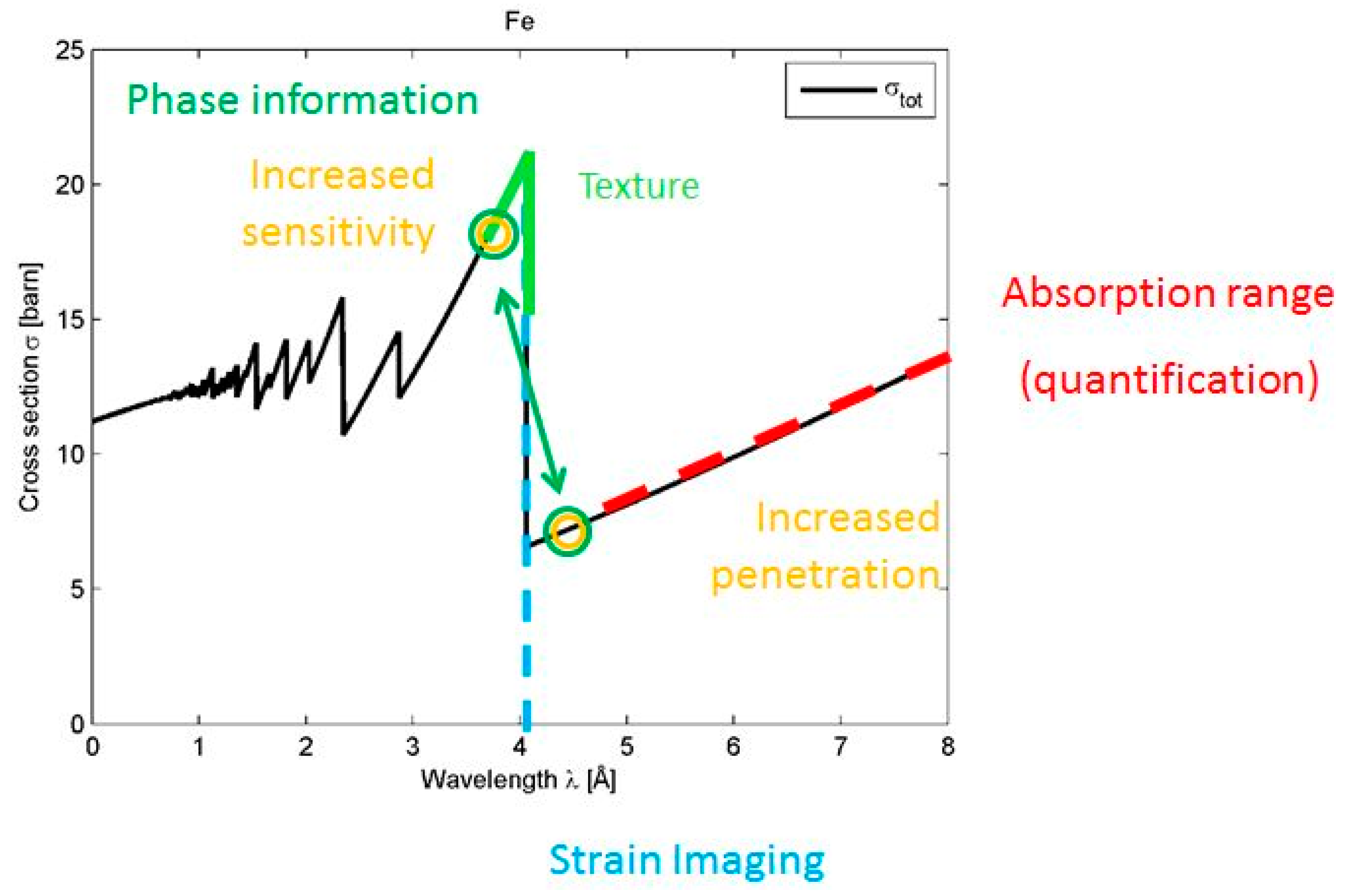
Figure 5.
Distribution of the 217 operational research reactors in the different global regions.
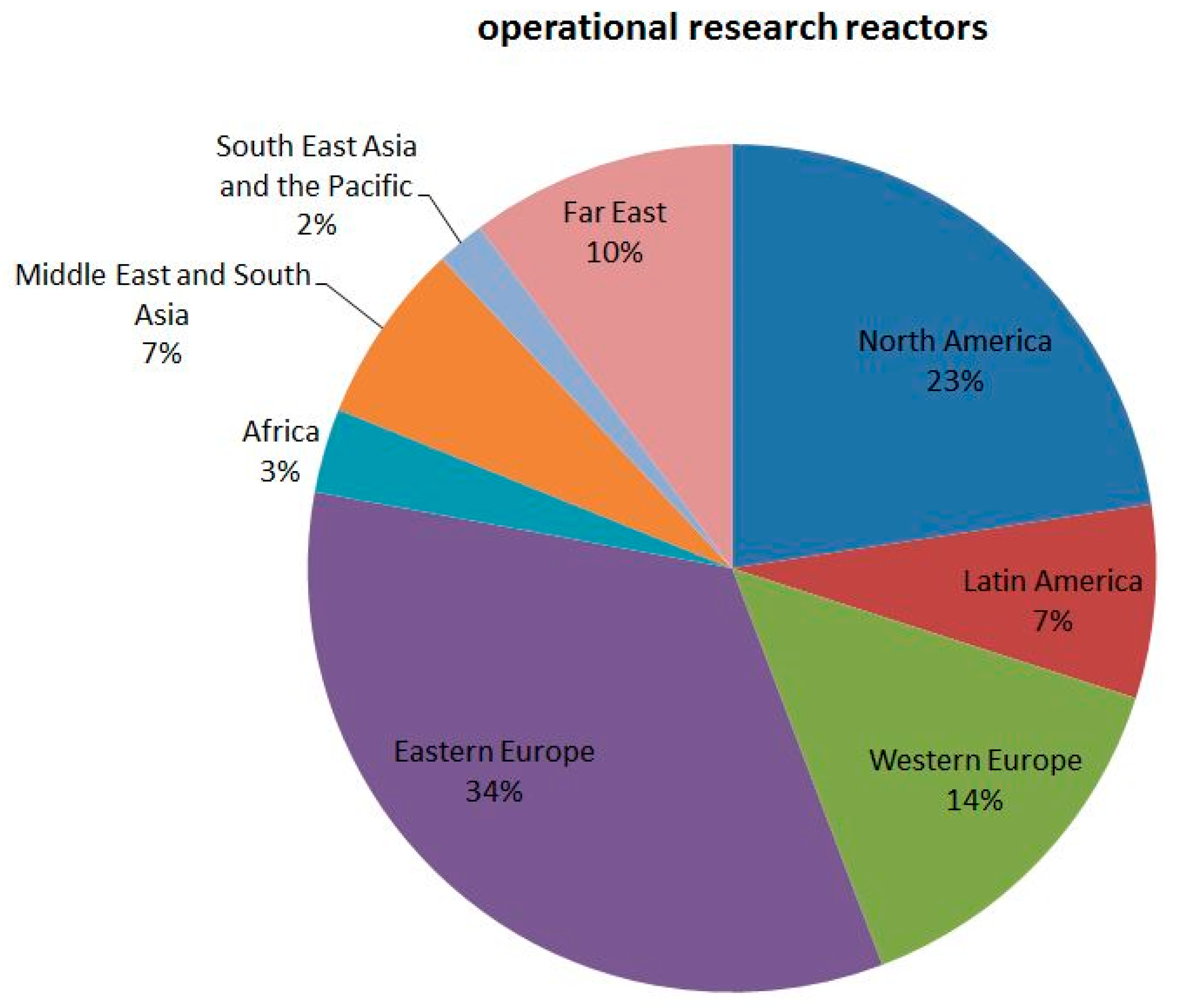
Figure 6.
Utilization of operational research reactors according to the declaration by the facilities’ managers fixed in the Research Reactor Data Base (RR DB) [15].
Figure 6.
Utilization of operational research reactors according to the declaration by the facilities’ managers fixed in the Research Reactor Data Base (RR DB) [15].


Table 1.
Neutron Imaging (NI) facilities at spallation neutron sources.
| Name | Source | Country | Status | Oper. Mode | Readiness |
|---|---|---|---|---|---|
| NEUTRA | SINQ | CH | user operation | continuous | 1997 |
| ICON | SINQ | CH | user operation | continuous | 2008 |
| BOA | SINQ | CH | Shared operation | continuous | 2013 |
| RADEN | JPARC | Japan | user operation | pulsed | 2015 |
| IMAT | ISIS-TS2 | UK | Facility test | pulsed | 2016 |
| VENUS | SNS | USA | project | pulsed | 2020? |
| ODIN | ESS | Europe | project | pulsed | 2019? |
Table 2.
Overview about all research reactors with their status (2017).
| Status | Developed Countries | Developing Countries | All Countries |
|---|---|---|---|
| Planned | 3 | 8 | 11 |
| Under construction | 4 | 4 | 8 |
| Operational | 135 | 82 | 217 |
| Temporary shutdown | 11 | 10 | 21 |
| Extended shutdown | 5 | 4 | 9 |
| Permanent shutdown | 103 | 19 | 122 |
| Under decommissioning | 19 | 1 | 20 |
| Decommissioned | 335 | 25 | 360 |
| Cancelled | 11 | 4 | 15 |
| Total | 626 | 157 | 783 |
Table 3.
Specification of research reactors according to their power, utilization and age.
| Mode | Number | Option |
|---|---|---|
| operational | 217 | |
| under construction | 8 | |
| planned | 11 | |
| power | 68 | between 1 kW and 1 MW |
| power | 48 | more than 1 MW |
| power | 63 | below 1 kW |
| utilization rate high | 42 | |
| age < 40 years | 93 | |
| age < 40 years | 143 |
Table 4.
List of the “state-of-the-art” NI facilities, reactor and spallation source based; since the spallation process is more efficient in the neutron output than fission, the power is not the direct indicator for performance comparison in these cases.
Table 4.
List of the “state-of-the-art” NI facilities, reactor and spallation source based; since the spallation process is more efficient in the neutron output than fission, the power is not the direct indicator for performance comparison in these cases.
| Country | Site | Institution | Facility | Neutron Source | Spectrum | Power (MW) | Status |
|---|---|---|---|---|---|---|---|
| Australia | Sydney | ANS TO | DINGO | OPAL reactor | thermal | 20 | operational |
| Germany | Munich-Garching | TU Munich | ANTARES | FRM-2 reactor | cold | 25 | operational |
| Germany | Munich-Garching | TU Munich | NECTAR | FRM-2 reactor | fast | 25 | operational |
| Germany | Berlin | HZB | CONRAD | BER-2 reactor | cold | 10 | operational |
| Hungary | Budapest | KFKI | NORMA | WWS-M reactor | cold | 10 | operational |
| Hungary | Budapest | KFKI | NRAD | WWS-M reactor | thermal | 10 | operational |
| Japan | Kyoto | Kyoto University | imaging beamline | MTR reactor | thermal | 5 | standby |
| Japan | Tokai | JAEA | imaging beamline | JRR-3M reactor | thermal | 20 | standby |
| Japan | Tokai | JAEA | RADEN | JPARC spallation | cold | 0.5 | operational |
| Korea | Daejon | KAERI | imaging beamline | HANARO reactor | thermal | 30 | operational |
| Russia | Dubna | JINR | imaging beamline | IBR-2M pulsed reactor | thermal | 2 | operational |
| Switzerland | Villigen | PSI | NEUTRA | SINQ spallation | thermal | 1 | operational |
| Switzerland | Villigen | PSI | ICON | SINQ spallation | cold | 1 | operational |
| UK | Oxfordshire | Rutherford Lab | IMAT | ISIS spallation | cold | 0.3 | operational |
| USA | Gaithersburg | NIST | BT-2 | NBSR reactor | Thermal | 20 | operational |
| USA | Gaithersburg | NIST | NG-6 | NBSR reactor | Cold | 20 | operational |
| USA | Oak Ridge | ORNL | CG-1D | HFIR reactor | Cold | 85 | operational |
| South Africa | Pelindaba | NECSA | SANRAD | SAFA RI reactor | thermal | 20 | standby |
Table 5.
Projects of new or upgraded NI facilities at reactors; for spallation sources see Table 1.
Table 5.
Projects of new or upgraded NI facilities at reactors; for spallation sources see Table 1.
| Country | Source | Facility | Site | Status |
|---|---|---|---|---|
| Argentina | RA10 | ASTOR | Boe nos Aires | project |
| Czech Republic | LVR-15 | NI | Rez near Prague | considerations |
| PR China | CARR | 2 NI | Beijing | project |
| France | ORPHEE | IMAGINE | Saclay | operational |
| Europe | ILL | D50 | Grenoble | shared with reflectometer |
| Norway | JEEP-II | NIMRAD | Kjeller | upgrade project |
| Netherlands | Delft RR | FISH | Delft | project |
| Jordan | new reactor | NI | Jordan | “day one” project |
| South Africa | SAFARI | SANRAD-II | Pelindaba | upgrade project |
| Russia | IBR-2 | NI | Dubna | improvements |
| South Korea | HANARO RR | NI | Daejon | upgrade project |
© 2017 by the author. Licensee MDPI, Basel, Switzerland. This article is an open access article distributed under the terms and conditions of the Creative Commons Attribution (CC BY) license (http://creativecommons.org/licenses/by/4.0/).
Share and Cite
MDPI and ACS Style
Lehmann, E.H. Neutron Imaging Facilities in a Global Context. J. Imaging 2017, 3, 52. https://doi.org/10.3390/jimaging3040052
AMA Style
Lehmann EH. Neutron Imaging Facilities in a Global Context. Journal of Imaging. 2017; 3(4):52. https://doi.org/10.3390/jimaging3040052
Chicago/Turabian StyleLehmann, Eberhard H. 2017. "Neutron Imaging Facilities in a Global Context" Journal of Imaging 3, no. 4: 52. https://doi.org/10.3390/jimaging3040052
Note that from the first issue of 2016, this journal uses article numbers instead of page numbers. See further details here.