Small Angle Scattering in Neutron Imaging—A Review
by
 ,
,
Markus Strobl
1,2,* ,
,
Ralph P. Harti
1,
Christian Gruenzweig
1,
Robin Woracek
3 and
Jeroen Plomp
4 1
Paul Scherrer Institut, PSI Aarebrücke, 5232 Villigen, Switzerland
2
Niels Bohr Institute, University of Copenhagen, Copenhagen 1165, Denmark
3
European Spallation Source ERIC, 225 92 Lund, Sweden
4
Department of Radiation Science and Technology, Technical University Delft, 2628 Delft, The Netherlands
*
Author to whom correspondence should be addressed.
J. Imaging 2017, 3(4), 64; https://doi.org/10.3390/jimaging3040064
Submission received: 6 November 2017
/
Revised: 6 December 2017
/
Accepted: 8 December 2017
/
Published: 13 December 2017
(This article belongs to the Special Issue Neutron Imaging)
Abstract
:Conventional neutron imaging utilizes the beam attenuation caused by scattering and absorption through the materials constituting an object in order to investigate its macroscopic inner structure. Small angle scattering has basically no impact on such images under the geometrical conditions applied. Nevertheless, in recent years different experimental methods have been developed in neutron imaging, which enable to not only generate contrast based on neutrons scattered to very small angles, but to map and quantify small angle scattering with the spatial resolution of neutron imaging. This enables neutron imaging to access length scales which are not directly resolved in real space and to investigate bulk structures and processes spanning multiple length scales from centimeters to tens of nanometers.
1. Introduction
The largest and maybe also broadest length scales that are probed with neutrons are the domains of small angle neutron scattering (SANS) and imaging. While small angle scattering probes the longest length scales measured in scattering covering mainly the nanometer range [1], imaging in contrast operates in real space and probes length scales from about 10 micrometers to centimeters and beyond [2,3]. It is only recently that the size ranges of these two techniques operating in reciprocal and real space, respectively, overlap. High resolution SANS methods such as double crystal USANS [1,4] and SESANS [5] have extended the range of SANS from nanometers far into the two digit micrometer regime, where conventional SANS, one of the most successful neutron techniques in material science, is limited due to flux and collimation requirements. Imaging on the other hand has improved its best spatial resolution from around 100 micrometers at the millennium to below 10 micrometers [6] recently. Another recent work has demonstrated how neutron imaging and scattering data can be combined efficiently on a scattering vector scale in order to cover an extended size range for statistical structure evaluation [7]. However, in SANS the measurement provides an average over sample sizes of typically up to three by three centimeters squared cross section, which correspondingly are assumed homogeneous on the macroscopic scale. In contrast to synchrotron x-ray small angle scattering, scanning with pencil beams over inhomogeneous sample volumes is very limited in its potential due to low flux and resulting long exposure times with neutrons. However, a few applications to probe, e.g., variations in rheological conditions with scanning SANS, exist [8] with limited spatial resolutions, i.e., beam sizes in the range of a few square millimeters. An in-situ combination of SANS and real space imaging appears not feasible when considering conventional instrumentation (Figure 1).
1.1. Basic Concept of Imaging
In conventional neutron imaging the transmission of a sample, i.e., the ratio of incoming and transmitted beam intensities I and I0, which is described by the Beer–Lambert law
is mapped with spatial resolution in (y,z) (compare coordinate axis system in Figure 1). The spatial resolution capability is achieved by a pinhole collimated beam where the achievable spatial resolution due to the beam geometry is limited by
with d being the blur on a detector at the distance l from the sample, which is positioned at a distance L downstream of the pinhole with diameter D. The beam cross section is in general larger than the sample size. Σ = Nσt = N(σa + σs) in Equation (1) is the total macroscopic cross section, referred to as the linear attenuation coefficient, where N is the number density of atoms and σt, σa and σs are the microscopic total, absorption and scattering cross sections respectively. Correspondingly this description assumes that scattered intensities are scattered to large angles and hence do not reach the transmission detector. This can lead to significant deviations of this simplified description from transmission imaging results, where a relatively large detector is placed close to the sample. While small angle scattering has hardly any impact on the transmission image due to involved angles and investigated length scales, incoherent scattering contributions and diffraction from crystalline structures close to the forward direction can be significant [9].
1.2. Basic Concept of SANS
In conventional small angle scattering the beam is collimated by two pinholes at a distance L from each other. The beam hitting the sample is smaller to equal the sample cross section and the transmitted beam in forward direction is masked out by a beam stop at the detector plane at a substantial distance l2, comparable to the collimation distance l1, downstream of the sample. This way only intensities scattered at small angles θ (app. 0.3 to 5 deg) out of the direct beam are detected. The modulus of the scattering vector q, which is the difference of the incoming wavevector k0 and the scattered wavevector k is defined as
where the small-angle approximation sinθ ≈ θ is used and consequently θ = λ/Ds = RD/l2 is measured through the distance l2 of the detector from the sample and the distance RD from the direct beam at which the scattered intensity is recorded. The scattering angle and scattering vector are related to the length scale Ds of the scattering structure through the Bragg equation and the scattering vector definition. Correspondingly the structure sizes probed by SANS Ds = 4π/q range from a few nm to a few 100 nm corresponding to a q-range between about 1 and 0.01 nm−1. The scattering function S(q) can be expressed as a Fourier transform of the scattering structure described by the even function of its scattering length density-density correlation function γ(r) [1]
being the scattering probability normalized to ∫S(q)dq = 1 by n0. Hence, with the total small angle scattering probability for a two phase system
where Δρ is the scattering length density contrast with being the scattering length density, bi being the bound coherent scattering lengths of the constituting elements of a homogeneous phase with a phase fraction φ, and with the sample thickness t the intensity distribution scattered at small angles out of the direct beam can be written as
Note that the small angle scattering function is symmetric as S(q) = S(−q) and the scattering function is invariant with respect to an exchange of the two phases (Babinet principle) [1].
1.3. Initial Approaches of SANS in Imaging
First attempts to probe small angle scattering with simultaneous spatial resolution have been reported using double crystal set-ups [10] (Figure 2) also referred to as Bonse–Hart camera [1,11]. In a double crystal diffractometer (DCD), the wavelength and divergence angles are coupled, which enables the detection of ultra-small angles despite of utilizing a divergent beam. This hence enables the characterization of structures from a few 100 nanometers to micrometers. In addition, the angular sensitivity is only in one dimension, on which the two dimensional scattering pattern of SANS is hence projected. This is referred to as slit-smeared SANS and can be described by the projection of the density–density correlation function onto one axis as
with normalization by the correlation length to achieve a dimensionless function again [12].
Imaging with such instruments was initially intended to enable differential phase contrast imaging of the refractive index distribution in a sample [13]. For this purpose the instrument can be equipped with an imaging detector, and depending on the specific instrument and purpose angular or spatial scanning are required [14,15]. Due to the fact that the relevant angular range of refraction matches the one of ultra-small angle scattering from structures in the micrometer and sub-micrometer range the method proved to be also suited to provide images of ultra-small angle scattering contrast. The principle feasibility could be demonstrated even for tomographic reconstructions of cross sections based on variations of small angle scattering. Concentration and size differences for example of nanoparticles in solution could be identified and located in bulk samples [10] (Figure 2). However, the coupling of angles and wavelengths by diffraction in the perfect single crystals of the instrument is also causing severe flux penalties, and therefore exposure times turn out to be too demanding for quantitative measurements and most practical application.
2. Beam Modulation Techniques for SANS and Imaging
At about the same time spatial beam modulation was on the one hand proposed for integral SANS measurements [16] and on the other hand realized for differential phase contrast neutron imaging [17]. While transversal beam modulation for SANS was proposed through a novel neutron spin-echo technique, in neutron imaging beam modulation was realized by the Talbot–Lau effect with phase and absorption gratings.
2.1. Neutron Grating Interferometry (NGI)
Neutron grating interferometers today are an established advanced neutron imaging tool. Grating interferometry with neutrons has proven particularly useful to detect magnetic domain walls and visualize magnetic domains even in the bulk of samples, which are not accessed by any other technique [18,19,20,21,22,23,24,25,26,27,28,29]. The Talbot–Lau grating interferometer, being the current standard in neutron grating interferometry consists of a set of three gratings (Figure 3). Central to this set-up is a phase grating (G1) with a period 2p in the micrometer range, which introduces an interference pattern. The interference pattern takes the form of a self image of the phase grating at certain regular distances L2 referred to as Talbot distances. For the conventionally used gratings inducing a phase shift of π, the period of the self-image, i.e., the modulation of the interference pattern is half the period of the grating. In order to provide sufficient beam coherence for diffraction at a micrometer sized structure a source grating, which is an absorption grating (G0), is installed in the divergent neutron beam close to the pinhole, which defines the real space spatial resolution of the imaging instrument. The period and distances are chosen such that the interference patterns related to individual beams from G0 are superposed constructively at the chosen Talbot distance, i.e., p0 = pL1/L2, where p0 is the period of the source grating and L1 is the distance from source grating to phase grating. Because the period of the interference pattern in the micrometer range cannot be detected directly with conventional state-of-the-art imaging detectors with pixel sizes >10 μm, another absorption grating (G2) with a period p is installed at the chosen Talbot distance L2 and the transversal beam modulation is translated into an intensity variation in each pixel of the imaging detector by stepwise scanning of one grating over about one period. The distances between source and phase gratings are typically of the order of meters and the Talbot distance of the order of centimeters. The sample can be placed before or after the phase grating, but for optimum spatial resolution performance should remain close to the detector. The Talbot–Lau interferometer is optimized for a certain wavelength with regards to the phase shift in the phase grating and with respect to the Talbot distance. However, the requirements for monochromatisation, i.e., wavelength resolution (dλ/λ ≈ 10%) and beam divergence are very modest, which enables to work with significantly brighter beams than in any other technique sensitive in the respective angular range. This hence enables efficient imaging measurements with high spatial resolution.
The angular sensitivity is defined by the micrometer sized period of the beam modulation which provides access to the ultra-small angle range even for sample to detector distances of centimeters, which in turn enables high spatial image resolution with modest beam collimation.
The basic idea of such set-up is that angular beam deviations induced by the sample alter the interference pattern. While the original motivation for building grating interferometers was to detect differential phase contrast, where the refraction of the beam shifts the phase of the interference pattern locally, the main application of the set-up became the detection of what is referred to as dark-field contrast, implying the loss of beam modulation visibility. The visibility is defined as V = (Imax − Imin)/(Imax + Imin), where Imax and Imin are the maximum and the minimum intensity of a modulation period across the beam. Visibility is lost through redistribution of intensity from the bright field (modulation maxima) to the dark field (modulation minima), which is the case in particular when the beam is scattered symmetrically like in small angle scattering or when magnetic features affect spin-up and spin-down components of the neutron conversely through refraction. However, also conventional refraction can due to limited direct spatial resolution lead to dark-field effects.
2.2. Spin-Echo Modulation (SEM)
As the neutron carries a magnetic moment antiparallel to its spin, controlled manipulation of the polarization of a beam has enabled several spin-echo techniques for elastic and inelastic neutron scattering, based on the analyses of the final beam polarization [30]. It has however also been found that the application of a specific spin echo approach enables the controlled spatial modulation of the beam and it has been proposed to utilize such modulation for small angle scattering studies [16]. Shortly after the first successful well controlled modulation has been achieved with a monochromatic beam [31] the ability for quantitative SANS measurements has been demonstrated for both a time-of-flight approach [32] and a monochromatic beam [33].
Here the principle set-up (Figure 3) consists of two main magnetic field regions in which the spins of a polarized neutron beam precess around the magnetic field vector aligned perpendicular to the spin polarization. The magnetic field regions have inclined boundaries with respect to the beam and are designed such that at a certain distance, depending on the field strengths B1 and B2 and the distance of the fields L1 and L2 to the detector, the spin polarization is a sinusoidal function of the transversal position on the detector only [16,31,32,33]. Hence, the installation of a spin filter, i.e., polarization analyser after the second precession field yields a spatially intensity modulated beam on the detector. The key condition is B1L1 = B2L2 and provides a beam modulation with a period.
where ϑ is the inclination of the field boundaries with respect to the beam and with and the gyromagnetic ratio and the mass of the neutron, respectively, and the Planck constant.
Also here the requirements on divergence and wavelength resolution are modest and the sample can be positioned anywhere after the first precession field. This allows the sample to be placed after the analyser and in close vicinity to the detector. Hence, highly efficient spatial resolved SANS studies with in principle high image resolution are possible [34]. The period of the modulation depends on the wavelength used, the magnetic field settings as well as on the field inclination. In contrast to the Talbot–Lau grating interferometer, where modulations are in the micrometer range, the to-date achieved modulation periods utilizing spin-echo range in the order of tenths of millimeters to millimeters [32,33,34,35]. This implies that the sensitivity range of such set-ups are currently ranging in the small angle to very small angle range. It however also implies, that the periods can mostly be resolved directly with state-of-the-art imaging detectors, but are superimposed to the real space images of the sample. This in turn requires slightly different data analyses strategies than the Talbot–Lau case and an entanglement of effective spatial resolution and small angle scattering resolution has to be considered carefully [36]. However, on the other hand the spin-echo set-up also implies enhanced flexibility as the set-up is suited to work with a broad range of wavelengths, can be tuned remotely (magnetic fields) and enables inversion of measurements through spin-up vs. spin-down measurements, which can be utilized for efficient analyses [36]. The ability to work with a broad range of wavelengths enables in particular to efficiently exploit a time-of-flight (ToF) approach enabling high efficiency and best exploitation of modern pulsed spallation neutron sources [32,34].
3. Dark-Field Imaging (DFI)
Dark-field imaging with grating interferometers designed for differential phase contrast imaging was introduced to neutron imaging about a decade ago [37] and underlined the ability for 3D tomographic studies of deviations in the scattering behavior in the volume of bulk samples.
3.1. Modulated Beam Dark-Field Contrast Theory
The contrast has been identified to be a local convolution of the small-angle scattering function with the modulation pattern, which allowed to assume a logarithmic behavior with thickness enabling tomographic reconstruction analogue to attenuation contrast [37]. This differs from dark-field contrast measured in DCDs as a broadening of the angular intensity distribution [10]. The logarithmic behavior of the visibility was later confirmed in a mathematical deduction [38] which was repeated specifically for neutrons [39].
Dark-field contrast imaging being sensitive to scattering to small, respective ultra-small angles became successful alone by its ability to detect locations in samples where such scattering takes place or is altered. Microstructural deviations hence provided additional image contrast from structures beyond direct real space resolution, and contrast for material compositions, which would otherwise not provide contrast in terms of attenuation. In neutron imaging the detection of magnetic structures providing a signal due to splitting of the spin states of an unpolarized beam became most prominent [18,19,20,21,22,23,24,25,26,27,28,29]. However, also the detection of regions with altered porosity or precipitations in particular in metallic samples has been demonstrated and applied [40,41] (Figure 4).
However, all applications first remained to a high degree qualitative especially with respect to the analyses of small angle scattering in terms of structural characteristics. A significant effort has been made in the x-ray community, strongly exploiting grating dark-field measurements especially in biological samples, to achieve a quantification of the signal through rigorous wave-field calculations. However, the straightforward quantitative context of the well-known and described conventional small angle scattering (SAS) theory and the dark-field signal has only recently been established [42] and since enables quantification analogue to well established SAS considerations and models. This has not only enabled the development of improved measurement strategies for quantitative dark-field imaging with full SAS characterization of probed structures, but has also led to implementation and usability of the specific analyses required in a standard SANS analyses software package.
Unlike in conventional SANS instruments but like in USANS in a DCD [1] scattering is only probed projected in a scattering plane and hence in one dimension. This so called slit-smearing has to be accounted for in calculating respectively interpreting the measured real space correlation function. However, this has been deduced and described in detail for another slit smeared real space scattering technique, namely Spin-Echo SANS [12] and has meanwhile been readily adapted for in the sans analyses software package SASfit [43].
A general theoretical description clarifying the context of SAS and modulated beam measurements, like those in grating interferometers and spin-echo modulated beam experiments, has been provided in Ref [42]. It has been shown that the convolution of the small angle scattering function S(q), where q is the modulus of the scattering vector, with the modulation function the visibility of which can be expressed as
where VS and V0 are the visibilities measured with and without the sample, respectively, is
It is hence a back transformation of the scattering function from Fourier space to real space and therefore yields the real space correlation function G of the scattering structure as
through
where V = (Imax − Imin)/(Imax + Imin) is the visibility of the modulation for an open beam (V0) and a sample measurement (Vs) in each pixel, respectively, and Δω is the specific phase shift of the modulation with respect to a specific scattering angle, respective scattering vector, and can be expressed by the set-up parameter ξ and the scattering vector q. ξ = λLs/p has been formulated for the first time in this context [42], being the autocorrelation length, i.e., the specific correlation length probed by a particular set-up. This parameter is characterized by the utilized wavelength λ, the modulation period p and the effective sample to detector distance Ls. Taking into account transmitted neutrons, the path integral through an extended sample and multiple scattering effects the final expression can be written as
Consequently, when the real space correlation function and the total scattering cross section S of a scattering structure are to be evaluated it is indispensable to perform a scan of the parameter ξ = λLs/p, which can be realized through scans of the wavelength, like in a ToF approach, a scan of the sample distance, which however also affects the real space spatial resolution, and the period of the interference pattern, which cannot be achieved with a fixed grating set-up.
3.2. Quantitative Dark-Field Contrast Imaging
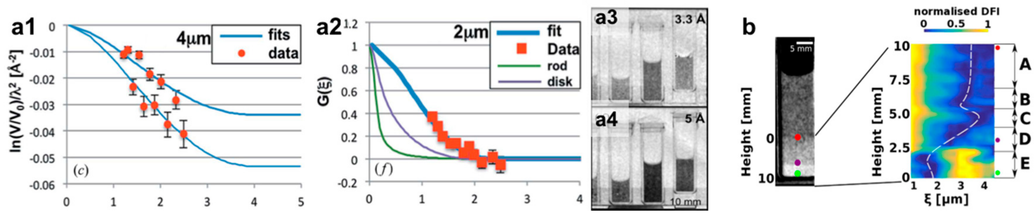
Despite these very recent developments several applications of this approach to probe simultaneously macroscopic structures through real space imaging and microscopic structures through spatial resolved extraction of the real space correlation function have been reported. The initial proof of principle has been realized through wavelength and sample distance scans to extract the particle size and concentration of spherical micrometer sized particles dispersed in water [44] (Figure 5a). Similar results have been reported later at other facilities [45], underlining a fast spread of the method and its potential. In one case sedimentation effects could be observed [44] (Figure 5a), while in a subsequent work the sedimentation and quasi crystallization of micrometer particles in solution could be studied in detail and the spatial resolution enabled to distinguish several different phases in the system [46] (Figure 5b). This latter study already utilized an upgraded Talbot–Lau grating interferometer, in which for the extension of the range in pure sample distance scan, the used order of the Talbot distance was increased, in order to enable extended scanning and investigated size range. These measurements underlined the strength of the method to investigate inhomogeneous systems on length scales distributed over several orders of magnitude from micrometers to centimeters. Not only the shape of particles (Figure 5a) based on the form factors in SAS but also structure factor related features, i.e., next neighbor correlations in highly concentrated solutions or densely packed crystal-like structures, i.e., a structure factor, can be identified and studied (Figure 5b). Unlike in conventional SANS experiments all these phases can spatially be resolved and separated when present in a single inhomogeneous sample. Therefore, the methods enable studies of inhomogeneity driven or creating processes and states.
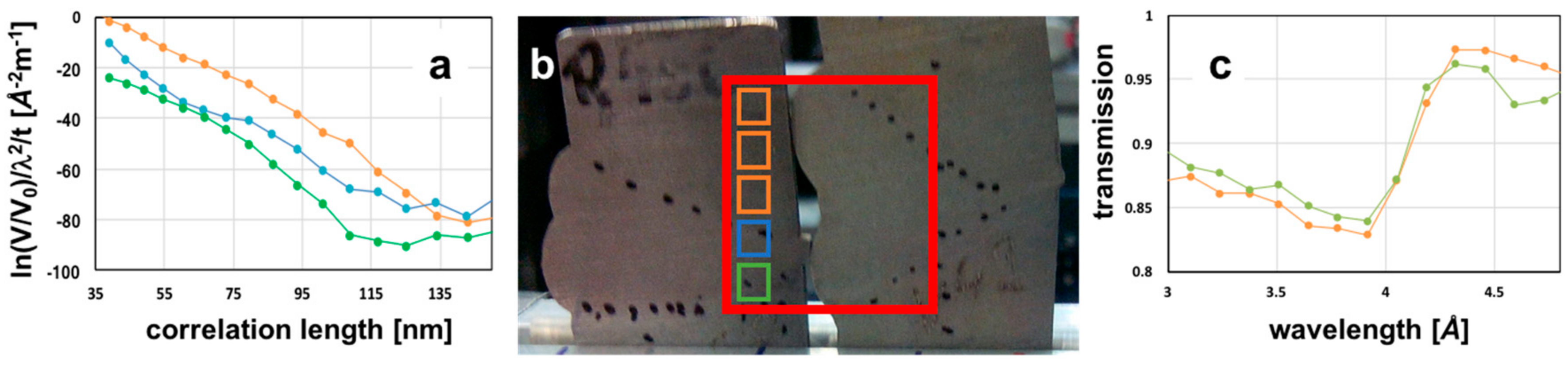
Similar studies have been performed also with the SEM-DFI approach, however, here nanoparticle systems around 100nm in size have been studied as reference systems and provide similar results as with the Talbot–Lau grating interferometer, but on a complementary length scale [34,44,46,47,48]. An example of a study on metallic welds is presented in Figure 6. In contrast to the image of Al fatigue test samples in Figure 4, which was taken at a single wavelength, this study has been performed in a ToF mode. Hence, the real space correlation functions of different parts of the weld were resolved ranging over about an order of magnitude. However, while significant differences between the areas of material not affected by the weld (marked orange), the heat affected zone (blue) and the weld itself (green) are detected, the microstructure is much more complex than in the systems of monodisperse particles introduced before. Therefore, a straight forward modelling and interpretation of the curves was so far not possible, but requires additional data. Nevertheless, it appears that on the given scale the heat affected zone and the weld itself display more inhomogeneities causing higher scattering levels than the original material, which might be due to porosity and precipitates occuring in the weld.
Here, however, another outstanding feature of wavelength resolved and particular ToF dark-field imaging can be demonstrated. Due to the fact that with modulated beam DFI not only dark-field contrast but simultaneously also attenuation contrast is probed, the wavelength dependent transmission provides access to yet another length scale. Bragg edges detected due to diffraction at the crystal lattice of powder-like crystalline materials enable to detect and analyze a variety of crystalline features established in the Ångstrom length scale regime. A comprehensive overview of the utilization of diffraction contrast in neutron imaging is provided in Ref [49]. Figure 6c displays the Bragg edge corresponding to bcc (110) of ferritic steel at around 4.05 Å and slight differences, likely due to microstructural discrepancies, between the heat affected zone and the original material of the weld. This implies that in principle multiple length scales from Ångstrom via nano- and micrometer to centimeters can be probed simultaneously in a single imaging experiment utilizing wavelength resolved (ToF) modulated beam dark-field imaging.
4. Discussion
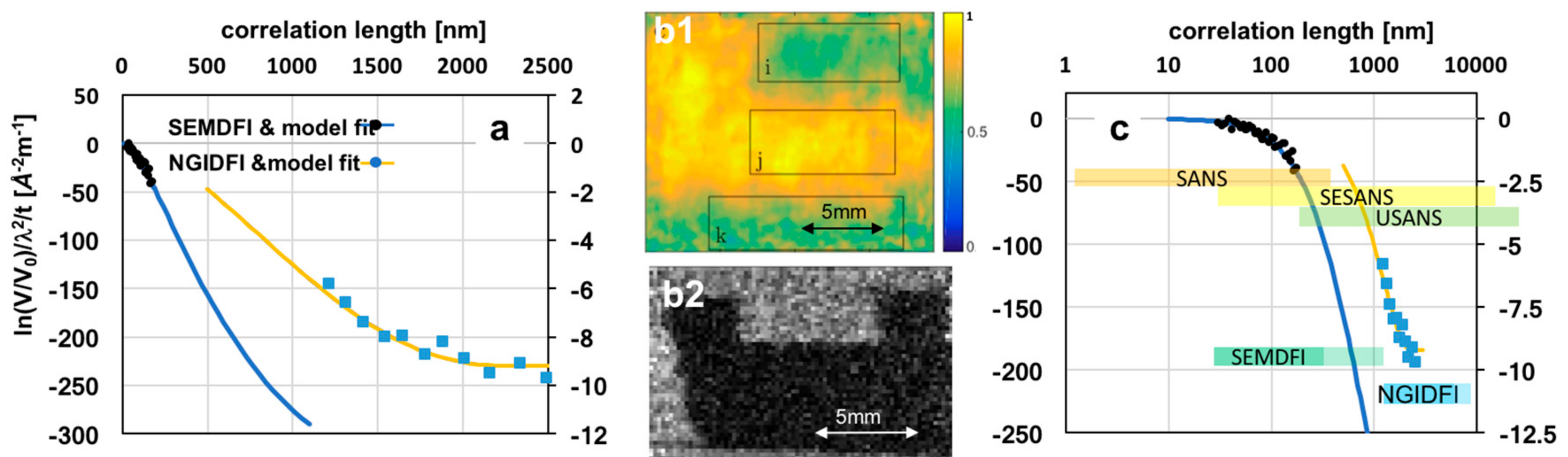
From the examples in Figure 5 it can be seen that the probed size range in Talbot–Lau interferometers is yet quite limited, due to wavelength dependence of the performance optimum of the grating set-up. The named successful extension to higher order Talbot distances improves the situation [46], but the probed length scale yet remains below one order of magnitude. The wavelength range that can reasonably be utilized is limited by different factors like the wavelength dependence of the set-up and gratings, but also of the total small angle cross section. The latter depends on wavelength squared, which implies a significant increase of scattering with wavelength, leading to saturation of the dynamic range of the measurements quickly. An example of saturated contrast is found in Figure 7b2, where in an approach of time-of-flight Talbot–Lau DFI the contrast of a sample probed complementarily with ToF SEM-DFI (Figure 7a,b1) was saturated, so that quantification was prohibited in the micrometer range. Therefore, a balance between low signal at short wavelengths and strong signal at long wavelengths has to be found, while the accuracy at both ends is limited by signal statistics and initial contrast. Although effort has been made to optimize visibility and measurement efficiency [50,51,52] severe limitations apply and visibility maxima with grating range only around 30%. Further extended distance scans on the other hand tend to impact the spatial resolution, yet an advantage of the Talbot–Lau method.
Figure 7a,b underlines the complementarity of NGI-DFI and SEM-DFI, both in terms of direct spatial resolution (Figure 7b) and SAS range (Figure 7a). In Figure 7a the data of a magnetic metal powder (Ferroxdure YXF1, BaFe12O19, Yuxiang Magnetic Materials Ind. Co., Ltd., Xiamen, China) measured with SEM-DFI is modelled by a random two-phase system and the data spans a range of correlation lengths from 30 to 175 nm. In the real space image of the measurement in Figure 7b1 the outline of the sample (marked with a box indicated with “i”) from which the data is extracted is not well defined. The spatial resolution is limited not only due to an extended sample to detector distance in this measurement of several 10 cm, but in particular due to the large modulation period of up to five millimeters, ultimately limiting the spatial resolution of the DFI image, but not necessarily the attenuation image [36]. In contrast, the image of the ToF NGI-DFI in Figure 7b2 provides a well resolved (approximately 100 micrometer resolution) dark-field image of the powder in a two-millimeter thick cuvette only a few centimeters from the detector and a modulation period of a few micrometer. However, the visibility is fully extinct. The NGI-DFI real space correlation function in Figure 7a is the data from Figure 5a2 modelled with an isolated hard-sphere model with a two-micrometer diameter. The scattering of this sample is more than two orders of magnitude less than the one of the powder sample at these long correlation length values, which prevents signal saturation. The length scale probed is about an order of magnitude higher and ranges only from 1.5 to 2.5 μm in this example taken at the first fractional Talbot distance. The example in Figure 5c extends the range to about half an order of magnitude mainly towards five micrometers. Correspondingly, in Figure 7c the same curves with a logarithmic scale of correlation lengths probed does not only compare the range probed by SEM-DFI and NGI-DFI but also puts them into context with the most applied small-angle neutron scattering techniques SANS, SESANS (operating analogue to DFI in the real space correlation length space) and (DCD)USANS. The representation for DFI methods already includes some range extensions achieved in recent development work, which shall to some extent still be discussed.
5. Outlook
Probing SANS through quantitative dark-field imaging is still a very young development and many results on the level of proof-of-principle. However, due to the fact that the results are very promising and reveal a high potential for detailed studies of inhomogeneous and real-life systems a significant effort is made to further develop techniques and explore their limits. In particular, closing the gap between SEM and NGI in real space as well as in correlation length, but especially also between correlation length and real space resolution is of high interest.
5.1. Progress in Grating-Based DFI
It has been outlined that optimization of Talbot–Lau grating arrangements have already allowed an extension of the range accessible and optimization and tailoring of data acquisition [46,50,51]. However, extending the correlation length range significantly to smaller length scales appears to require variations of the modulation approach with gratings.
Novel geometries considered in grating-based DFI include a so called far-field interferometer previously introduced for x-rays and light [53] (Figure 3c). Similar to SEM-DFI the periods are long, a broader wavelength spectrum can be utilized and remotely controlled scanning of a wider range of autocorrelation lengths is enabled also by the possible grating distance scans. A drawback is however a large sample to detector distance required to achieve correlation lengths comparable to Talbot–Lau interferometers. Hence, a significant trade-off between spatial resolution and flux is to be taken into account for imaging and spatial resolution of the dark-field contrast image itself is limited by the large period. This technique has not yet been included in Figure 7c, because the actually achievable range and trade-offs are not yet explored in detail.
5.2. Progress in Spin-Echo Modulated DFI
So far the limitation for spin-echo-based modulation was to achieve small enough modulation periods to improve the direct spatial DFI resolution and to push the DFI correlation length range to higher values. Significant progress has been achieved recently with two techniques that allow much higher magnetic fields than the conventional wire wound coils. The first is the development of the superconducting magnetic Wollaston prisms [54] for spin-echo modulated SANS, which could easily be transferred to quantitative SEM-DFI. This setup in particular allows a very compact design. A second technique involving radio frequency coils has been tested recently in a development at a testbeamline of the European Spallation Source (ESS) at the Helmholtz Zentrum Berlin (HZB) [55] and will be reported elsewhere. Such approach is comparable to solutions for SESANS at pulsed sources [56] which has proven to be a very stable and flexible solution. The two methods allowed to push the period significantly and towards the limit of what can be still directly resolved with the ToF imaging detector [57] utilized for the ToF approaches [32,34]. This enables on the one hand a reduction of the sample to detector distance, which generally enables better spatial resolution. However, better spatial resolution for the DFI signal is in particular enabled by the smaller modulation periods realized this way. At the same time the accessible range could be extended to several 100 nm, close to overlapping the NGI range. In order to resolve even smaller periods in ToF, if detector resolution cannot be improved significantly at good efficiency, also here a grating analyser could be utilized in such range as has been demonstrated for monochromatic spin-echo modulated SANS [33]. In a time-of-flight experiment this would require ramping of the magnetic fields synchronized with the source pulses. The feasibility of such a technique has been demonstrated already as well [58]. It has to be noted however, that this impacts the accessible range as the wavelength dependence of the probed correlation length changes from wavelength square to a linear dependence, hence a significantly smaller range for the same wavelength range.
6. Conclusions
In conclusion, SANS can play a significant role in neutron imaging in the future. Recent developments underline the potential to quantitatively probe SANS in imaging experiments with good spatial resolution. A number of developments are further fostering this option and improving the probable ranges as well as data quality and modelling. The ability to profit from ToF furthermore provides the perspective for the technique to prosper at modern high flux pulsed spallation sources and in turn paves the way for new scientific opportunities in soft as well as hard condensed matter research, enabling the investigation of structures on several length scales simultaneously. It has been outlined that even the length scales of crystal lattices, the domain of neutron diffraction become accessible through the very same data recorded at once and adding to the macroscopic scale of direct real space resolution and the microscopic scale of SAS in the nanometer to micrometer range. This also implies that inhomogeneous systems and whole real-world devices and processes might move into the focus of advanced dark-field contrast studies. To realize such potential there is still a lot of room for improvements and developments pushing the current limitations. For grating-based methods this is mainly done at conventional continuous source imaging instruments [17,37,46,59,60,61], but finds its way also to pulsed sources like JPARC and ISIS with a view on their pioneering dedicated ToF imaging instrumentation [62,63,64,65,66]. The spin-echo technique has so far been explored at test beamlines in Berlin [55] and Delft [34], but also here capabilities become available at the named spallation sources.
Acknowledgments
Previously unpublished work in this review article is partially funded by the Swiss National Science Foundation under project number 153304.
Author Contributions
All authors contributed equally.
Conflicts of Interest
The authors declare no conflict of interest.
References
- Feigin, L.; Svergun, D. Structure Analysis by Small-Angle X-ray and Neutron Scattering; Plenum Press: New York, NY, USA, 1987. [Google Scholar]
- Strobl, M.; Kardjilov, N.; Hilger, A.; Manke, I.; Banhart, J. Topical Review: Advances in neutron radiography and tomography. J. Phys. D 2009, 42, 21. [Google Scholar] [CrossRef]
- Williams, S.H.; Hilger, A.; Kardjilov, N.; Manke, I.; Strobl, M.; Douissard, P.A.; Martin, T.; Riesemeier, H.; Banhart, J. Detection system for microimaging with neutrons. J. Instrum. 2012, 7, P02014. [Google Scholar] [CrossRef]
- Treimer, W.; Strobl, M.; Hilger, A. Development of a tuneable channel cut crystal. Phys. Lett. A 2001, 289, 151–154. [Google Scholar] [CrossRef]
- Rekveldt, M.T. Novel SANS instrument using neutron spin echo. Nucl. Instrum. Methods B 1996, 114, 366–370. [Google Scholar] [CrossRef]
- Trtik, P.; Lehmann, E.H. Progress in high-resolution neutron imaging at the Paul Scherrer Institut—The Neutron Microscope project. J. Phys. Conf. Ser. 2016, 746, 01200. [Google Scholar] [CrossRef]
- Zhou, Z.; Bouwman, W.G.; Schut, H.; Desert, S.; Jestin, J.; Hartmann, S.; Pappas, C. From Nanopores to Macropores: Fractal Morphology of Graphite. Carbon 2016, 96, 541–547. [Google Scholar] [CrossRef]
- Penfold, J.; Tucker, I. Flow-induced effects in mixed surfactant mesophases. J. Phys. Chem. B 2007, 111, 9496–9503. [Google Scholar] [CrossRef] [PubMed]
- Raventos, M.; Lehmann, E.; Boin, M.; Morgano, M.; Hovind, J.; Harti, R.; Valsecchi, J.; Kaestner, A.; Carminati, C.; Boillat, P.; et al. A Monte Carlo approach for scattering correction towards quantitative neutron imaging of polycrystals. J. Appl. Cryst. Under review.
- Strobl, M.; Treimer, W.; Hilger, A. Small angle scattering signals for (neutron) computerized tomography. Appl. Phys. Lett. 2004, 85, 488–490. [Google Scholar] [CrossRef]
- Bonse, U.; Hart, M. Tailless X-ray single crystal reflection curves obtained by multiple reflection. Appl. Phys. Lett. 1965, 7, 238. [Google Scholar] [CrossRef]
- Andersson, R.; van Heijkamp, L.F.; de Schepper, I.M.; Bouwman, W.G. Analysis of spin-echo small-angle neutron scattering. J. Appl. Cryst. 2008, 41, 868–885. [Google Scholar] [CrossRef]
- Treimer, W.; Strobl, M.; Hilger, A.; Seifert, C.; Feye-Treimer, U. Refraction as imaging signal for computerized (neutron) tomography. Appl. Phys. Lett. 2003, 83, 398–400. [Google Scholar] [CrossRef]
- Strobl, M.; Treimer, W.; Hilger, A.; Feye-Treimer, U. Neutron tomography in double crystal diffractometers. Phys. B Condens. Matter 2004, 350, 155–158. [Google Scholar] [CrossRef]
- Strobl, M.; Treimer, W.; Hilger, A. First realisation of a three-dimensional refraction contrast computerised neutron tomography. Nucl. Instrum. Methods B 2004, 222, 653–658. [Google Scholar] [CrossRef]
- Gaehler, R. A Certain Class of Beam Modulation Techniques and Its Potential Applications; PNCMI Polarized Neutron School: Berlin, Germany, 2006. [Google Scholar]
- Pfeiffer, F.; Grünzweig, C.; Bunk, O.; Frei, G.; Lehmann, E.; David, C. Neutron phase imaging and tomography. Phys. Rev. Lett. 2006, 96, 215505. [Google Scholar] [CrossRef] [PubMed]
- Reimann, T.; Schulz, M.; Grünzweig, C.; Kaestner, A.; Bauer, A.; Böni, P.; Mühlbauer, S. Neutron Dark-Field Imaging of the Domain Distribution in the Intermediate State of Lead. J. Low Temp. Phys. 2016, 182, 107–116. [Google Scholar] [CrossRef]
- Reimann, T.; Mühlbauer, S.; Schulz, M.; Betz, B.; Kaestner, A.; Pipich, V.; Böni, P.; Grünzweig, C. Visualizing the morphology of vortex lattice domains in a bulk type-II superconductor. Nat. Commun. 2016, 6, 8813. [Google Scholar] [CrossRef] [PubMed] [Green Version]
- Betz, B.; Rauscher, P.; Harti, R.P.; Schäfer, R.; van Swygenhoven, H.; Kaestner, A.; Hovind, J.; Lehmann, E.; Grünzweig, C. In-situ visualization of stress-dependent bulk magnetic domain formation by neutron grating interferometry. Appl. Phys. Lett. 2016, 108, 012405. [Google Scholar] [CrossRef]
- Rauscher, P.; Betz, B.; Hauptmann, J.; Wetzig, A.; Beyer, E.; Grünzweig, C. The influence of laser scribing on magnetic domain formation in grain oriented electrical steel visualized by directional neutron dark-field imaging. Sci. Rep. 2016, 6, 38307. [Google Scholar] [CrossRef] [PubMed]
- Betz, B.; Rauscher, P.; Harti, R.P.; Schäfer, R.; Irastorza-Landa, A.; van Swygenhoven, H.; Kaestner, A.; Hovind, J.; Pomjakushina, E.; Lehmann, E.; et al. Magnetization Response of the Bulk and Supplementary Magnetic Domain Structure in High-Permeability Steel Laminations Visualized In Situ by Neutron Dark-Field Imaging. Phys. Rev. Appl. 2016, 6, 024023. [Google Scholar] [CrossRef]
- Betz, B.; Rauscher, P.; Harti, R.P.; Schäfer, R.; van Swygenhoven, H.; Kaestner, A.; Hovind, J.; Lehmann, E.; Grünzweig, C. Frequency-Induced Bulk Magnetic Domain-Wall Freezing Visualized by Neutron Dark-Field Imaging. Phys. Rev. Appl. 2016, 6, 024024. [Google Scholar] [CrossRef]
- Grünzweig, C.; Siebert, R.; Betz, B.; Rauscher, P.; Schäfer, R.; Lehmann, E. Determination of Bulk Magnetic Volume Properties by Neutron Dark-Field Imaging. Phys. Procedia. 2015, 69, 413–419. [Google Scholar] [CrossRef]
- Grünzweig, C.; David, C.; Bunk, O.; Kohlbrecher, J.; Lehmann, E.; Lai, Y.W.; Schäfer, R.; Roth, S.; Lejcek, P.; Kopecek, J.; et al. Visualizing the propagation of volume magnetization in bulk ferromagnetic materials by neutron grating interferometry. J. Appl. Phys. 2010, 107, 09D308. [Google Scholar] [CrossRef]
- Lee, S.W.; Kim, K.; Kwon, O.Y.; Kardjilov, N.; Dawson, M.; Hilger, A.; Manke, I. Observation of Magnetic Domains in Insulation-Coated Electrical Steels by Neutron Dark-Field Imaging. Appl. Phys. Express 2010, 3, 10. [Google Scholar] [CrossRef]
- Manke, I.; Kardjilov, N.; Schäfer, R.; Hilger, A.; Strobl, M.; Dawson, M.; Grünzweig, C.; Behr, G.; Hentschel, M.; David, C.; et al. Three-dimensionl imaging of magnetic domains. Nat. Commun. 2010, 1, 125. [Google Scholar] [CrossRef] [PubMed]
- Grünzweig, C.; David, C.; Bunk, O.; Dierolf, M.; Frei, G.; Kühne, G.; Schäfer, R.; Pofahl, S.; Rønnow, H.; Pfeiffer, F. Bulk magnetic domain structures visualized by neutron dark-field imaging. Appl. Phys. Lett. 2008, 93, 112504. [Google Scholar] [CrossRef]
- Grünzweig, C.; David, C.; Bunk, O.; Dierolf, M.; Frei, G.; Kühne, G.; Kohlbrecher, J.; Schäfer, R.; Lejcek, P.; Rønnow, H.; et al. Neutron decoherence imaging for visualizing bulk magnetic domain structures. Phys. Rev. Lett. 2008, 101, 025504. [Google Scholar] [CrossRef] [PubMed]
- Mezei, F.; Gutberlet, T. (Eds.) Neutron Spin Echo Spectroscopy; Springer Verlag: Berlin/Heidelberg, Germany, 2003. [Google Scholar]
- Bouwman, W.G.; Duif, C.P.; Plomp, J.; Wiedenmann, A.; Gähler, R. Combined SANS–SESANS, from 1 nm to 0.1 mm in one instrument. Phys. B Condens. Matter 2011, 406, 2357. [Google Scholar] [CrossRef]
- Strobl, M.; Tremsin, A.S.; Hilger, A.; Wieder, F.; Kardjilov, N.; Manke, I.; Bouwman, W.G.; Plomp, J. TOF-SEMSANS—Time-of-flight spin-echo modulated small-angle neutron scattering. J. Appl. Phys. 2012, 112, 014503. [Google Scholar] [CrossRef]
- Strobl, M.; Bouwman, W.G.; Wieder, F.; Duiff, C.; Hilger, A.; Kardjilov, N.; Manke, I. Using a grating analyser for SEMSANS investigations in the very small angle range. Phys. B Condens. Matter 2012, 407, 4132–4135. [Google Scholar] [CrossRef]
- Strobl, M.; Sales, M.; Plomp, J.; Bouwman, W.G.; Tremsin, A.S.; Kaestner, A.; Pappas, C.; Habicht, K. Quantitative Neutron Dark-field Imaging through Spin-Echo Interferometry. Sci. Rep. 2015, 5, 16576. [Google Scholar] [CrossRef] [PubMed]
- Sales, M.; Plomp, J.; Habicht, K.; Strobl, M. Investigating time-of-flight spin-echo modulation for small-angle neutron scattering through experiments and simulation. J. Appl. Cryst. 2015, 48, 92–96. [Google Scholar] [CrossRef]
- Sales, M.; Plomp, J.; Bouwman, W.G.; Tremsin, A.S.; Habicht, K.; Strobl, M. On the analysis of time-of-flight spin-echo modulated dark-field imaging data. J. Phys. Conf. Ser. 2017, 862, 012026. [Google Scholar] [CrossRef]
- Strobl, M.; Grünzweig, C.; Hilger, A.; Manke, I.; Kardjilov, N.; David, C.; Pfeiffer, F. Neutron dark-field tomography. Phys. Rev. Lett. 2008, 101, 123902. [Google Scholar] [CrossRef] [PubMed]
- Bech, M.; Bunk, O.; Donath, T.; Feidenhans’l, R.; David, C.; Pfeiffer, F. Quantitative X-ray dark-field computed tomography. Phys. Med. Biol. 2010, 55, 5529–5539. [Google Scholar] [CrossRef] [PubMed]
- Gruenzweig, C.; Kopecek, J.; Betz, B.; Kaestner, A.; Jefimovs, K.; Kohlbrecher, J.; Gasser, U.; Bunk, O.; David, C.; Lehmann, E.; et al. Quantification of the neutron dark-field imaging signal in grating interferometry. Phys. Rev. B 2013, 88, 125104. [Google Scholar] [CrossRef]
- Hilger, A.; Kardjilov, N.; Kandemir, T.; Manke, I.; Banhart, J.; Penumadu, D.; Manescu, A.; Strobl, M. Revealing micro-structural inhomogeneities with dark-field neutron imaging. J. Appl. Phys. 2010, 107, 036101. [Google Scholar] [CrossRef]
- Brooks, A.J.; Ge, J.; Kirka, M.M.; Dehoff, R.R.; Bilheux, H.Z.; Kardjilov, N.; Manke, I.; Butler, L.G. Porosity detection in electron beam-melted Ti-6Al-4V using high-resolution neutron imaging and grating-based interferometry. Prog. Addit. Manuf. 2017, 2, 125–132. [Google Scholar] [CrossRef]
- Strobl, M. General solution for quantitative dark-field contrast imaging with grating interferometers. Sci. Rep. 2014, 4, 7243. [Google Scholar] [CrossRef] [PubMed]
- Kohlbrecher, J.; Studer, A. Transformation cycle between the spherically symmetric correlation function, projected correlation function and differential cross section as implemented in SASfit. J. Appl. Cryst. 2017, 50, 1395–1403. [Google Scholar] [CrossRef]
- Strobl, M.; Betz, B.; Harti, R.P.; Hilger, A.; Kardjilov, N.; Manke, I.; Gruenzweig, C. Wavelength dispersive dark-field contrast: Micrometer structure resolution in neutron imaging with gratings. J. Appl. Cryst. 2016, 49, 569–573. [Google Scholar] [CrossRef]
- Reimann, T.; Mühlbauer, S.; Horisberger, M.; Betz, B.; Böni, P.; Schulz, M. The new neutron grating interferometer at the ANTARES beamline: Design, principles and applications. J. Appl. Cryst. 2016, 49, 1488–1500. [Google Scholar] [CrossRef]
- Harti, R.P.; Strobl, M.; Betz, B.; Jefimovs, K.; Kagias, M.; Gruenzweig, C. Sub-pixel correlation length neutron imaging: Spatially resolved scattering information of microstructures on a macroscopic scale. Sci. Rep. 2017, 7, 44588. [Google Scholar] [CrossRef] [PubMed]
- Strobl, M.; Grazzi, F. From Scattering in Imaging to Prospects at Pulsed Sources. Neutron News 2015, 2, 23–26. [Google Scholar] [CrossRef]
- Betz, B.; Harti, R.P.; Strobl, M.; Hovind, J.; Kaestner, A.; Lehmann, E.; van Swygenhoven, H.; Grünzweig, C. Quantification of the sensitivity range in neutron dark-field imaging. Rev. Sci. Instrum. 2015, 86, 123704. [Google Scholar] [CrossRef] [PubMed]
- Woracek, R.; Santisteban, J.; Fedrigo, A.; Strobl, M. Diffraction in neutron imaging—A review. Nucl. Instrum. Meth. A 2017, in press. [Google Scholar] [CrossRef]
- Harti, R.; Strobl, M.; Morgano, M.; Valsecchi, J.; Grünzweig, C. Statistical uncertainty in the dark-field and transmission signal of grating interferometry. Rev. Sci. Instrum. 2017, 88, 103704. [Google Scholar] [CrossRef] [PubMed]
- Harti, R.; Kottler, C.; Valsecchi, J.; Jefimovs, K.; Kagias, M.; Strobl, M.; Grünzweig, C. Visibility simulation of realistic grating interferometers including grating geometries and energy spectra. Opt. Express 2017, 25, 1019–1029. [Google Scholar] [CrossRef] [PubMed]
- Lee, S.W.; Zhou, Y.; Zhou, T.; Jiang, M.; Kim, J.; Ahn, C.W.; Louis, A.K. Visibility studies of grating-based neutron phase contrast and dark-field imaging by using partial coherence theory. J. Korean Phys. Soc. 2013, 63, 2093–2097. [Google Scholar] [CrossRef]
- Hussey, D.S.; Miao, H.; Yuan, G.; Pushin, D.A.; Sarenac, D.; Huber, M.G.; Jacobson, D.L.; LaManna, J.M.; Wen, H. Demonstration of a white beam far-field neutron interferometer for spatially resolved small angle neutron scattering. arXiv, 2016; arXiv:1606.03054. [Google Scholar]
- Li, F.; Parnell, S.R.; Bai, H.; Yang, W.; Hamilton, W.A.; Maranville, B.B.; Ashkar, R.; Baxter, D.V.; Cremer, J.T.; Pynn, R. Spin echo modulated small-angle neutron scattering using superconducting magnetic Wollaston prisms. J. Appl. Crystallogr. 2016, 49, 55–63. [Google Scholar] [CrossRef]
- Woracek, R.; Hoffmann, T.; Bullat, M.; Sales, M.; Habicht, K.; Andersen, K.; Strobl, M. The testbeamline of the European Spallation Source—Instrumentation development and wavelength frame multiplication. Nucl. Instr. Methods A. 2016, in press. [Google Scholar] [CrossRef]
- Rekveldt, M.T.; Plomp, J.; Bouwman, W.G.; Kraan, W.H.; Grigoriev, S.; Blaauw, M. Spin-echo small angle neutron scattering in Delft. Rev. Sci. Instrum. 2005, 76, 033901. [Google Scholar] [CrossRef]
- Tremsin, A.S.; Vallerga, J.V.; McPhate, J.B.; Siegmund, O.H.W.; Feller, W.B.; Crow, L.; Cooper, R.G. On the possibility to image thermal and cold neutron with sub-15 mm spatial resolution. Nucl. Instrum. Methods Phys. Res. A 2008, 592, 374. [Google Scholar] [CrossRef]
- Sales, M.; Plomp, J.; Habicht, K.; Tremsin, A.S.; Bouwman, W.G.; Strobl, M. Wavelength-Independent Constant Period Spin-Echo Modulated Small Angle Neutron Scattering. Rev. Sci. Instrum. 2016, 87, 063907. [Google Scholar] [CrossRef] [PubMed]
- Lee, S.W.; Jun, Y.K.; Kwon, O.Y. A Neutron Dark-field Imaging Experiment with a Neutron Grating Interferometer at a Thermal Neutron Beam Line at HANARO. J. Korean Phys. Soc. 2011, 58, 730–734. [Google Scholar]
- Lee, S.W.; Hussey, D.S.; Jacobson, D.L.; Sim, C.M.; Arif, M. Development of the Grating Phase Neutron Interferometer at a Monochromatic Beam Line. Nucl. Instrum. Methods Phys. Res. A 2009, 605, 16–20. [Google Scholar] [CrossRef]
- Kim, J.; Lee, S.W.; Gyuseong, C. Visibility evaluation of a neutron grating interferometer operated with a polychromatic thermal neutron beam. Nucl. Instrum. Methods Phys. Res. A 2014, 746, 26–32. [Google Scholar] [CrossRef]
- Shinohara, T.; Kai, T.; Oikawa, K.; Segawa, M.; Harada, M.; Nakatani, T.; Ooi, M.; Aizawa, K.; Sato, H.; Kamiyama, T.; et al. Final design of the Energy-Resolved Neutron Imaging System “RADEN” at J-PARC. J. Phys. Conf. Ser. 2016, 746, 012007. [Google Scholar] [CrossRef]
- Seki, Y.; Shinohara, T.; Parker, J.D.; Yashiro, W.; Momose, A.; Kato, K.; Kato, H.; Sadeghilaridjani, M.; Otake, Y.; Kiyanagi, Y. Development of Multi-colored Neutron Talbot–Lau Interferometer with Absorption Grating Fabricated by Imprinting Method of Metallic Glass. J. Phys. Soc. Jpn. 2017, 86, 044001. [Google Scholar] [CrossRef]
- Minniti, T.; Kockelmann, W.; Burca, G.; Kelleher, J.F.; Kabra, S.; Zhang, S.Y.; Pooley, D.E.; Schooneveld, E.M.; Mutamba, Q.; Sykora, J. Materials analysis opportunities on the new neutron imaging facility IMAT@ISIS. J. Instrum. 2016, 11, C03014. [Google Scholar] [CrossRef]
- Impression of LARMOR Instrument in SESANS Mode. Available online: https://larmor.weblog.tudelft.nl/ (accessed on 6 November 2017).
- Strobl, M. The Scope of the Imaging Instrument Project ODIN at ESS. Phys. Procedia 2015, 69, 18–26. [Google Scholar] [CrossRef]
Figure 1.
Instrument set-ups: conventional small angle neutron scattering (SANS) [1] and imaging geometry [2] and principle.
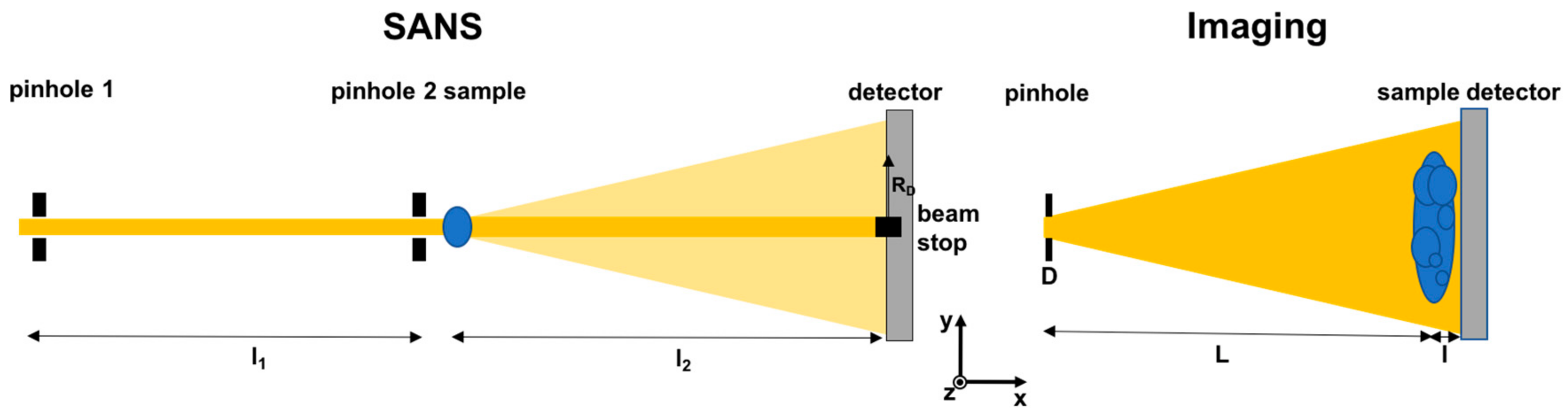
Figure 2.
Double crystal diffractometer for imaging (Left) and results (Right) of differential phase (matrix, Top) and dark-field contrast (Bottom) tomographies of a reference sample filled with different sizes and concentrations of beta-carotine particles in solution as visualized in the tomography (color code); Results Reproduced from [10], with the permission of AIP Publishing.
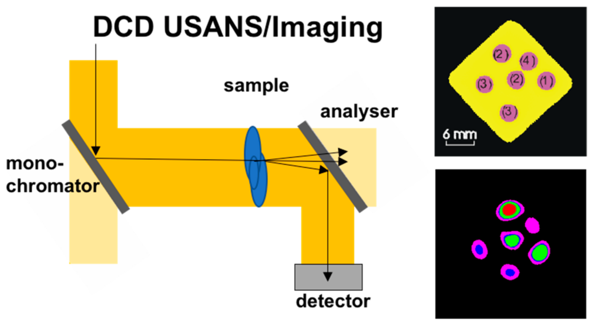
Figure 3.
Modulated beam imaging set-ups schematic: Talbot–Lau grating interferometer (Top) and spin-echo modulation set-up (Middle) as well as a novel development referred to as far-field grating interferometer (Bottom).
Figure 3.
Modulated beam imaging set-ups schematic: Talbot–Lau grating interferometer (Top) and spin-echo modulation set-up (Middle) as well as a novel development referred to as far-field grating interferometer (Bottom).
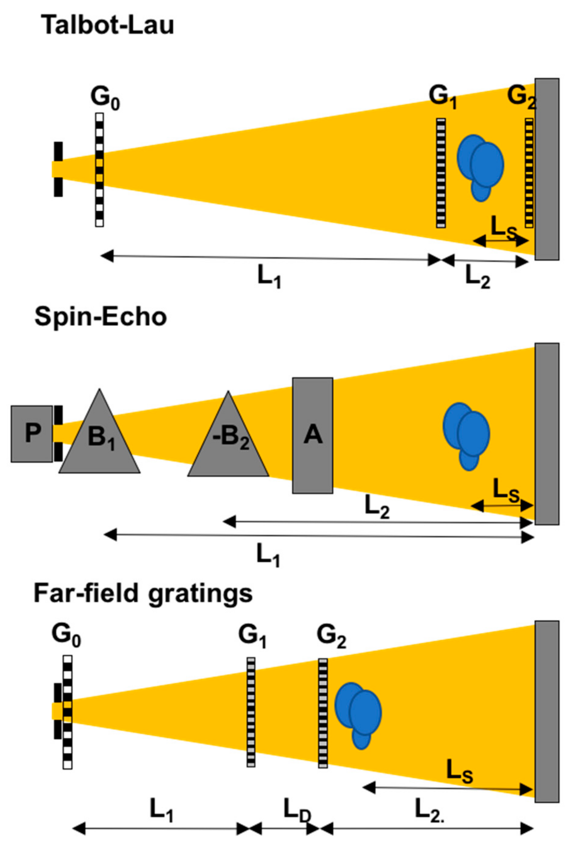
Figure 4.
Qualitative dark-field imaging: (a) materials distinguished by scattering originating from precipitates and porosity. Reproduced from [40], with the permission of AIP Publishing; (b) visualizing magnetic domain walls in 3D [27].
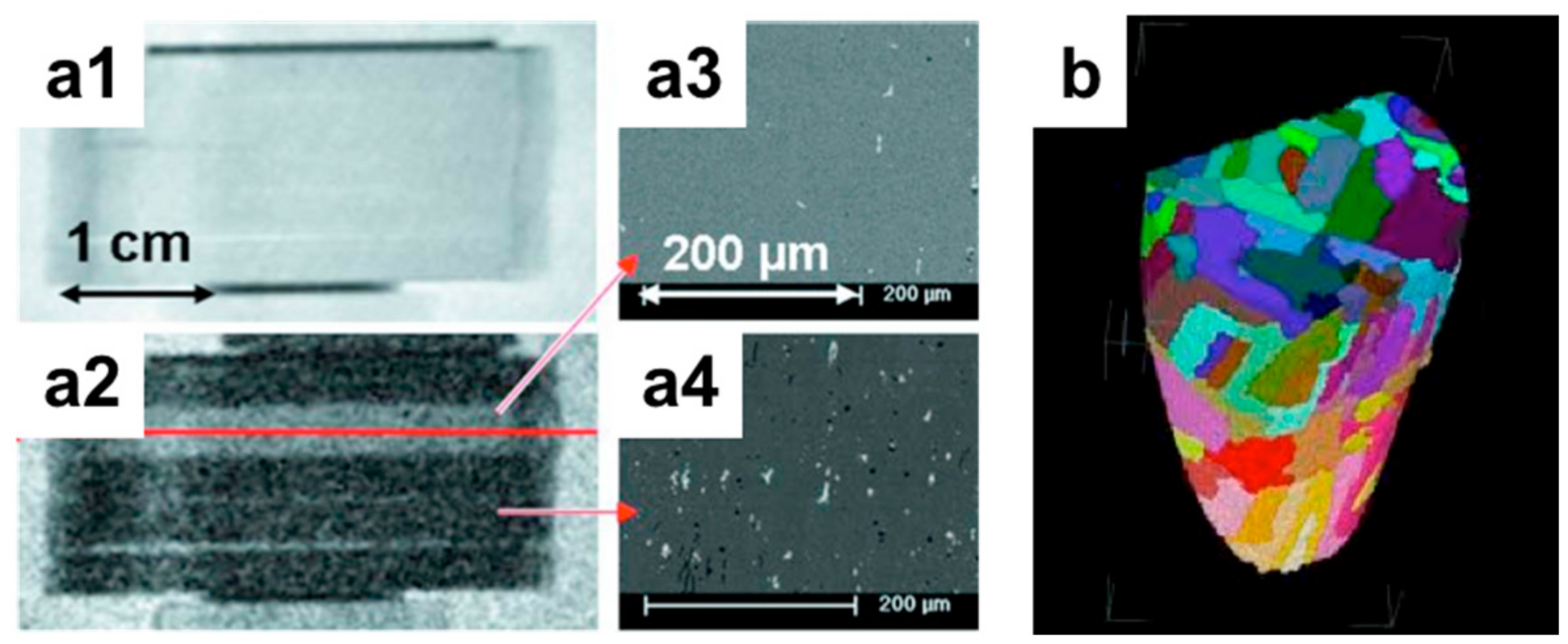
Figure 5.
Quantitative neutron grating interferometry dark-field imaging (NGI-DFI): (a) spherical polystyrene particles diluted in H2O/D2O; loss of concentration observed over time (sedimentation) of 4 μm particles (a1); results corresponding to form factor of spherical particles with dimeter of 2 μm measured (a2); (a3,a4) corresponding dark-field images at 3.3 Å and 5 Å, respectively [44]; (b) DFI of polystyrene spheres sedimenting in an aqueous dilution where a diluted phase a concentrated phase and a quasi-crystalline phase can be identified and in particular a depletion zone (C) between high concentration and crystallization regions is found [46]; (a1) to (a4) are reproduced with permission of the International Union of Crystallography from [44].

Figure 6.
Time-of-flight dark-field imaging of steel welds: (a) real space correlation functions of three distinct areas of a 1.5 mm thick steel weld; (b) photograph of the sample(s) with the color coded regions of interest analysed in (a) and (c); (c) simultaneously recorded wavelength dependent transmission data of two color coded regions of interest (b) in the weld, displaying the Bragg edge pattern around the Fe(110) Bragg edge.

Figure 7.
Resolution ranges and limitations correlation length and direct real space resolution for different DFI approaches; (a) modelled data from wavelength dispersive NGI-DFI and time-of-flight (ToF) SEM-DFI; (b1) real space image of the SEM-DFI [34] and (b2) of ToF NGI-DFI; (c) curves from (a) on logarithmic correlation length scale and including ranges of different neutron techniques to explore the corresponding size ranges (note these apply only to the size range, i.e., x-axis).

© 2017 by the authors. Licensee MDPI, Basel, Switzerland. This article is an open access article distributed under the terms and conditions of the Creative Commons Attribution (CC BY) license (http://creativecommons.org/licenses/by/4.0/).
Share and Cite
MDPI and ACS Style
Strobl, M.; Harti, R.P.; Gruenzweig, C.; Woracek, R.; Plomp, J. Small Angle Scattering in Neutron Imaging—A Review. J. Imaging 2017, 3, 64. https://doi.org/10.3390/jimaging3040064
AMA Style
Strobl M, Harti RP, Gruenzweig C, Woracek R, Plomp J. Small Angle Scattering in Neutron Imaging—A Review. Journal of Imaging. 2017; 3(4):64. https://doi.org/10.3390/jimaging3040064
Chicago/Turabian StyleStrobl, Markus, Ralph P. Harti, Christian Gruenzweig, Robin Woracek, and Jeroen Plomp. 2017. "Small Angle Scattering in Neutron Imaging—A Review" Journal of Imaging 3, no. 4: 64. https://doi.org/10.3390/jimaging3040064
Note that from the first issue of 2016, this journal uses article numbers instead of page numbers. See further details here.