Article

Range Imaging for Motion Compensation in C-Arm Cone-Beam CT of Knees under Weight-Bearing Conditions †

1
Pattern Recognition Lab, Department of Computer Science, Friedrich-Alexander-Universität Erlangen-Nürnberg, 91052 Erlangen, Germany
2
Erlangen Graduate School in Advanced Optical Technologies (SAOT), 91052 Erlangen, Germany
3
Radiological Sciences Laboratory, Stanford University, Stanford, CA 94305, USA
*
Author to whom correspondence should be addressed.
This paper is an extended version of our paper published in Bier, B.; Unberath, M.; Geimer, T.; Maier, J.; Gold, G.; Levenston, M.; Fahrig, R.; Maier, A. Motion Compensation Using Range Imaging in C-Arm Cone-Beam CT. In the Annual Conference on Medical Image Understanding and Analysis. Springer: Cham, Switzerland, 2017; pp. 561–570.
J. Imaging 2018, 4(1), 13; https://doi.org/10.3390/jimaging4010013
Submission received: 7 November 2017 / Revised: 3 January 2018 / Accepted: 3 January 2018 / Published: 6 January 2018
(This article belongs to the Special Issue Selected Papers from “MIUA 2017”)

Abstract

:
C-arm cone-beam computed tomography (CBCT) has been used recently to acquire images of the human knee joint under weight-bearing conditions to assess knee joint health under load. However, involuntary patient motion during image acquisition leads to severe motion artifacts in the subsequent reconstructions. The state-of-the-art uses fiducial markers placed on the patient’s knee to compensate for the induced motion artifacts. The placement of markers is time consuming, tedious, and requires user experience, to guarantee reliable motion estimates. To overcome these drawbacks, we recently investigated whether range imaging would allow to track, estimate, and compensate for patient motion using a range camera. We argue that the dense surface information observed by the camera could reveal more information than only a few surface points of the marker-based method. However, the integration of range-imaging with CBCT involves flexibility, such as where to position the camera and what algorithm to align the data with. In this work, three dimensional rigid body motion is estimated for synthetic data acquired with two different range camera trajectories: a static position on the ground and a dynamic position on the C-arm. Motion estimation is evaluated using two different types of point cloud registration algorithms: a pair wise Iterative Closest Point algorithm as well as a probabilistic group wise method. We compare the reconstruction results and the estimated motion signals with the ground truth and the current reference standard, a marker-based approach. To this end, we qualitatively and quantitatively assess image quality. The latter is evaluated using the Structural Similarity (SSIM). We achieved results comparable to the marker-based approach, which highlights the potential of both point set registration methods, for accurately recovering patient motion. The SSIM improved from 0.94 to 0.99 and 0.97 using the static and the dynamic camera trajectory, respectively. Accurate recovery of patient motion resulted in remarkable reduction in motion artifacts in the CBCT reconstructions, which is promising for future work with real data.

1. Introduction

The development of recent C-arm cone-beam computed tomography (CBCT) scanners has allowed the imaging of the human knee joint under weight-bearing conditions. To this end, experiments with conventional as well as with dedicated extremity scanners have been conducted. The flexibility of such systems facilitates novel scanning protocols and allows to scan patients in an upright, standing position, bearing their own weight in a natural pose [1,2]. Such acquisitions could have high diagnostic value, since it has been shown that the knee joint shows different mechanical properties under load [3]. However, there are several challenges that must be overcome to generate reconstructions of satisfying image quality for use in clinical practice. These challenges include the scanner calibration of unusual, horizontal C-arm trajectories [4], overexposure of the object border [5], radiation dose considerations [2], optimizing scanner geometry [6], scatter [6], or a limited field of view [7]. Though, the most dominant factor decreasing image quality is involuntary patient motion. During the scan that can take up to 30 s, motion leads to inconsistencies in the projection images. Thus, severe motion artifacts appear in the reconstructions, which manifest as streaks, double edges, and image blur. These artifacts heavily reduce the diagnostic value of the images. This is especially true for applications investigating fine structures such as trabecular bone or the deformation of cartilage [8]. Hence, recovery of patient motion in the reconstruction process in crucial.
Motion estimation and compensation is well understood in computed tomography (CT) and CBCT. In terms of motion, the main difference between these modalities is their acquisition time. While CT acquires images in approximately 300 ms per 360 rotation with a 64 row detector [9], in CBCT an acquisition can take up to 30 s. Acquisition time is a major factor of motion, since a faster acquisition results in less motion. One solution to reduce the scan time could be to reduce the number of available projections, but this leads to lower image quality. If motion is periodic, gating strategies based on surrogate signals, e.g., from the electrocardiogram [10] or respiratory belts [11] can be used. Using these signals, projections of the object in the same motion state can be used for reconstruction. However, this is not feasible for non-periodic motion. Furthermore, past studies have also investigated the use of 2D/2D or 2D/3D registration approaches for motion compensation [12,13]. These compensate motion by registering the measured projection images to the reconstructed volume in an iterative manner. In general, motion correction in CBCT can be interpreted from two perspectives: first, it can be seen as a patient motion tracking problem; second, it can be seen as correcting a miscalibrated scanner geometry. However, both perspectives are closely related and can be equated to one another, resulting in the same motion correction step: both try to correct the scanner geometry, which minimizes motion induced artifacts in the reconstructed images by estimating a motion state for each projection.
In acquisitions under weight-bearing conditions, methods based on surrogates do not relate due to the none periodicity of the knee motion. Further, registration methods are hardly applicable due to overlapping Tibia, Femur, Fibula, and Patella of both legs. A first step to reduce the motion is to immobilize the patient as far as possible during the scan. For this purpose, approaches with cushions [2] or holding devices [1] are established to stabilize the patient. However, if motion remains, further motion correction is indispensable. The current state-of-the-art approach uses fiducial markers placed on the patient’s knee surface [1,14]. Due to the high attenuation of such markers, they can be tracked in the 2D projection images. Using these, 3D reference positions are defined and correspondences between the 2D and 3D marker positions are established. By minimizing their projection error, rigid three dimensional motion is estimated for each projection image. Although this method has been applied in several clinical studies [1,15,16,17,18], it has certain drawbacks: marker placement is time consuming, tedious, and user experience is required to accurately place the markers such that they do not overlap in the projection images. This can lead to errors in the estimated motion. To overcome the need for placing markers, image-based methods have been investigated: first, Unberath et al. registered the acquired projection images to maximum intensity projections of an initial motion corrupted reconstruction, but only 2D detector shifts have been evaluated [19]. Sisniega et al. proposed an auto focus method to estimate the motion compensated trajectory by optimizing the image sharpness and entropy in the reconstruction [20]. They assumed the motion to be locally rigid and thus selected only a small region of interest in which they were able to compute high quality reconstructions. Another approach by Berger et al. uses 2D/3D registration of a segmented bone from a motion free supine acquisition with the acquired projection images [21]. Results showed improved sharpness at the bone outline, but a motion free supine scan might not always be available. Moreover, epipolar and Fourier consistency conditions, which minimize the inconsistency in the projection data, have been investigated for this application [22,23,24].
In this study, we focus on a conventional CBCT scanner, where in contrast to the dedicated CBCT scanner described by Carrino et al. [2], the X-ray source and the detector are mounted on a flexible robotic C-arm, capable to scan both legs at the same time [1]. During scanning, the C-arm rotates on a horizontal circular trajectory around the patient and acquires projection images from different views [1,4,14]. Such an image acquisition setup is illustrated in Figure 1. In order to correct for patient motion, we utilize a range camera. Range cameras have already been used in several other clinical applications [25] such as augmented reality [26,27], motion estimation in PET/SPECT imaging [28], and patient positioning and motion estimation in radiotherapy [29]. Very similar to the approach described here, Fotouhi et al. investigated the feasibility on improving iterative reconstruction quality by incorporating information of an RGB-D camera [30].
First results of our approach have been published recently, where we investigated the capability of using a range camera to correct for patient motion in acquisitions under weight-bearing conditions [31]: an Iterative Closest Point (ICP) registration was used to estimate motion on the point clouds observed by the range camera. Up to now, only translational motion and a static range camera position have been evaluated. Within this work, we bring our previous approach to clinical applicability by (1) optimizing for three dimensional rigid body motion; (2) a pair wise ICP [32] and a probabilistic group wise registration method [33] are compared; and (3) a second, more complex range camera trajectory is investigated that assumes the camera to be mounted directly on the source (or detector) of the CBCT system. These scenarios are evaluated on two simulated datasets: the first one is a high quality reconstruction of a supine knee acquisition and the second one is the XCAT knee phantom. Results are compared to the ground truth, the uncorrected, and the marker-based motion corrected reconstruction [21]. Image quality of the reconstructions is evaluated qualitatively and by using the Structural Similarity (SSIM) metric. Furthermore, the estimated motion signals are compared and discussed.

2. Materials and Methods
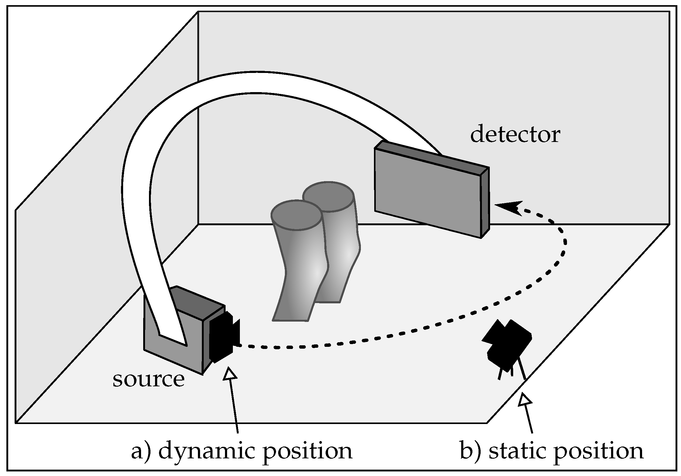
In this section, the basic principles of CBCT image reconstruction, its underlying geometry, and the influence of motion in such scans are explained briefly. We then describe how patient motion was simulated, estimated, and incorporated using range imaging, and finally, describe the performed experiments in detail.

2.1. Imaging Setup

An overview of our proposed imaging setup is depicted in Figure 1: the C-arm with the X-ray source and the detector rotates around the standing patient. Simultaneously, a range camera, placed either on the floor or directly on the C-arm, observes the knee surface. We refer to these positions as static and dynamic camera positions throughout the paper. Equivalence in the scene captured by the X-ray system and the dynamic setup has been investigated previously by Habert et al. [34]. As an example, in Figure 2 we show a projection image and point cloud acquired at the same time and motion state of the object. A synchronized and co-calibrated system is assumed. The position of the range camera has an important influence on the cross calibration, object occlusion, motion estimation, and spatial requirements. In this paper we seek to investigate, which camera setup is most appropriate for our application:
  • Motion estimation: compared to the static case, where the same scene is observed in each frame, partial overlap between the point clouds occurs in the dynamic scenario. This happens since the range camera rotates with the C-arm around the object. Registration of partly overlapping point clouds is an especially challenging problem if a smooth, cylindrical object, such as the human knee is imaged. Therefore, two point cloud registration methods are compared to investigate their motion estimation capability in both scenarios.
  • Calibration: co-calibration of the C-arm and the range camera is required to incorporate the estimated motion of the range camera correctly into the reconstruction. A calibration has to be done only once for the dynamic case, since their relative position is constant.
  • Object occlusion: in an unpredictable medical environment, staff, patient clothing, or the C-arm might temporarily occlude the field of view of the range camera. Missing or partly missing points can heavily result in errors in the motion estimation. In the dynamic setup, the trajectory of the C-arm has to be selected carefully, such that always the object of interest is visible. Otherwise it could happen that the knee surface is occluded by the second knee. However, in the static setup the rotating C-arm could also cover partly the camera’s field of view.
  • Spatial requirements: limited space in the medical examination room has also to be considered for the camera setup. A camera mounted on the C-arm takes up less space. Furthermore, the static camera is prone to be touched, which would require a new calibration. This is rather unlikely for the position on the C-arm.

2.2. Cone-Beam Computed Tomography and Motion

In C-arm CBCT projection images are usually acquired on a circular trajectory. A common acquisition to perform 3D imaging is a short scan [35], where the system rotates 180 plus its fan angle. In order to reconstruct a volume from a stack of acquired projections, the imaging geometry for every image has to be known precisely. This is described with projection matrices for each projection [36]. A projection matrix P j is a 3 × 4 matrix, which defines the projection of an object onto the detector for a given discrete time point j [37]. In general, it can be decomposed into an intrinsic matrix K j R 3 × 3 and an extrinsic matrix E j R 4 × 4 , containing the rotation and the translation:
P j = K j 1 0 0 0 0 1 0 0 0 0 1 0 R j t j 0 1 .
R j R 3 × 3 and t j R 3 describe the rotation and translation of the camera. Thus, the geometry of a single view can be manipulated by multiplying an affine transformation M j to the right side on the projection matrix P j , yielding an updated projection matrix P j :
P j = P j M j .
In the same way, rigid patient motion (described by M j ) can be included into the scenario. As mentioned earlier, including object motion or correcting a miscalibrated scanner geometry is compensated the same way. This is possible since only the relative position of the CBCT system to the object is important for reconstruction.

2.3. Data Generation

Our proposed method relies on point clouds and projection data, acquired at the same time under the same motion state of the object (example images are shown in Figure 2). In this section, we describe how we created this data.
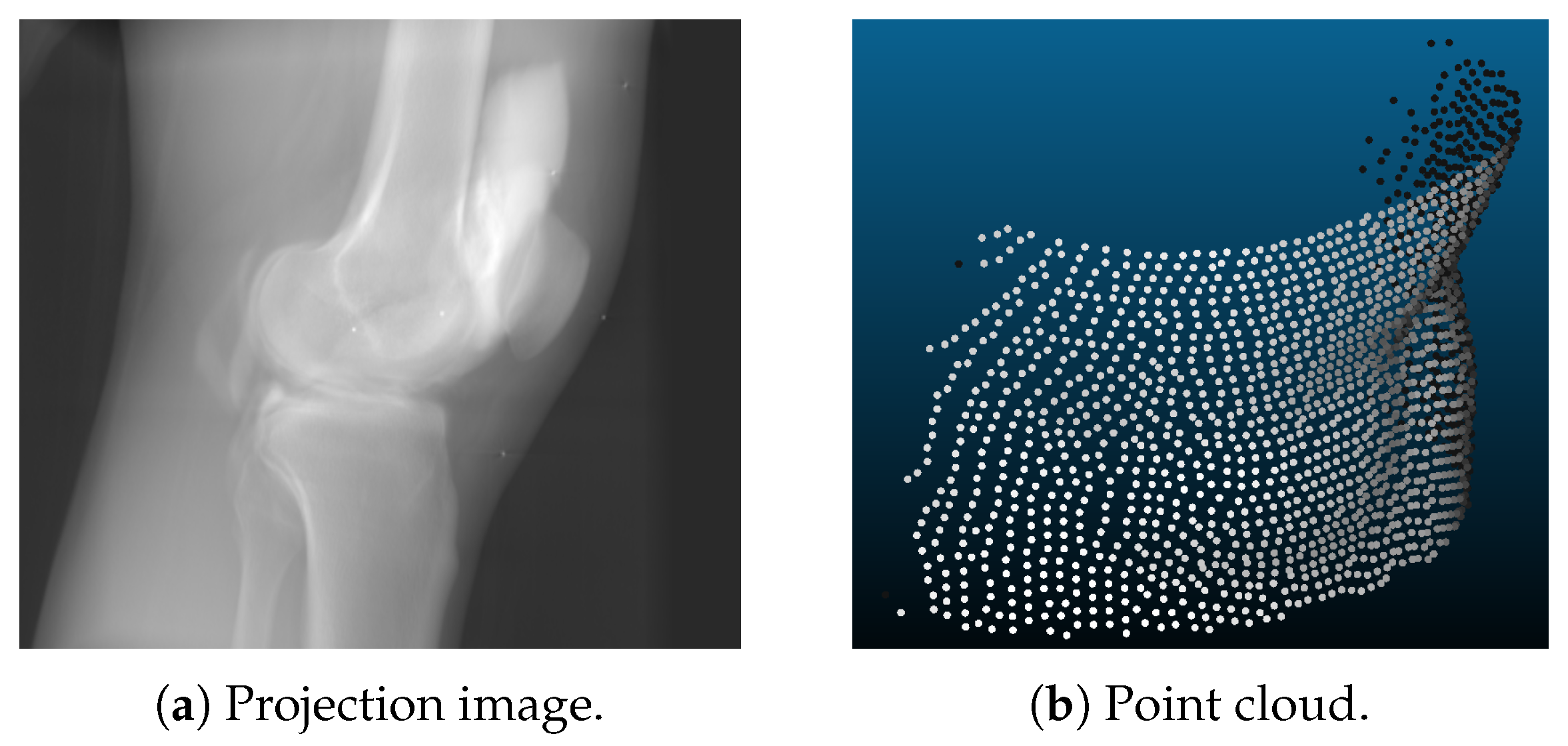
  • Point clouds are generated using a voxelized volume of the object. For each discrete time step, the volume was transformed rigidly. The surface of this volume was then sampled using a ray casting approach. The range camera was modeled using projective geometry with properties similar to the Microsoft Kinect One v2 [38,39]: the sampled points lie on a grid like pattern, as shown in Figure 2b. In the isocenter of the C-arm scanner, which is the area of interest for CBCT scanning, the distance of the sampled points was approximately 1.4 mm in image space. A depth resolution of 1 mm was applied with a camera distance of 75 cm. These settings were the same for the static and the dynamic camera position. The only difference lied in the different trajectories of both setups. For the experiments, we further created point clouds with and without noise. This noise was approximated as Gaussian noise with a standard deviation of 1 mm.
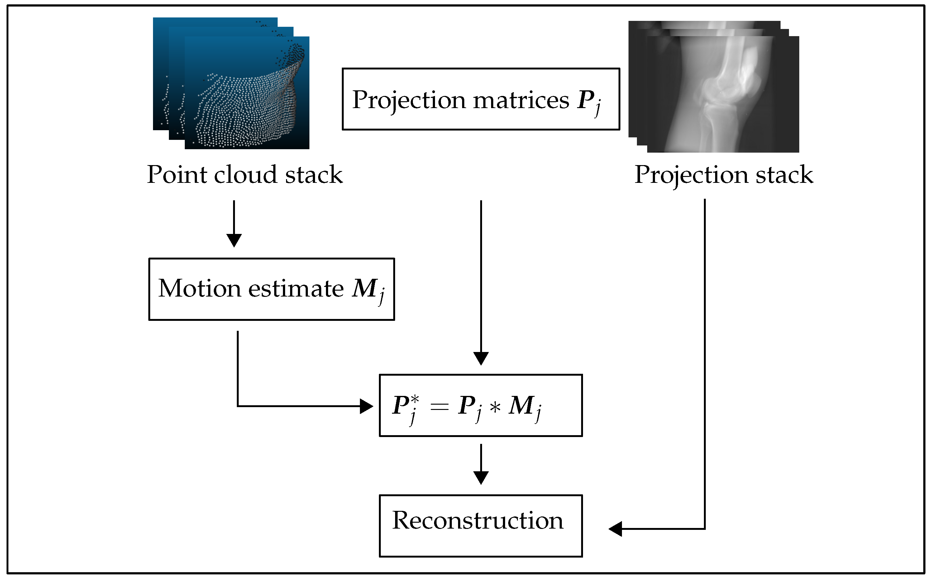
  • X-ray projections are created from the same volume used for the point clouds. Given a C-arm trajectory, i.e., several projection matrices that describe the C-arm rotation around the object, the volume was forward projected yielding a stack of 2D projection images. Motion was incorporated using Formula (2). This was done using CONRAD, an open-source software framework dedicated for cone-beam imaging simulation and reconstruction [40].
  • Motion used to corrupt the data was realistic knee motion of a standing subject, measured with an VICON (Vicon Motion Systems Ltd, Oxford, UK) motion capture system [1]. The same motion pattern was applied in the point clouds and projection images simulation.

2.4. Motion Estimation Using Range Imaging

Figure 3 outlines the work flow of our proposed method: we started with a stack of point clouds and projections with their corresponding calibration data (projection matrices). For each time step j, a transformation M j was estimated using point cloud registration. Using Equation (2), motion corrected projection matrices were subsequently calculated. These were then used to compute motion corrected reconstructions. We evaluated two different point cloud registration algorithms. The first one was a point-to-plane ICP algorithm applied in a pair wise manner. The second was a probabilistic group wise approach [33].

2.4.1. Iterative Closest Point Algorithm

The Iterative Closest Point (ICP) algorithm minimizes point-wise distances between two point clouds, by iteratively performing two steps: first, point correspondences between two point clouds are established by searching for the minimal distance between points. In a second step, a rigid transformation is computed by minimizing the squared distances between the corresponding pairs using for example the Singular Value Decomposition. In contrast to this conventional ICP algorithm, the point to surface ICP optimizes the distance of points in one sample, to the surface of the other point cloud, in order to estimate the desired rigid transformation that aligns the two. See [32] for more detailed mathematical formulations of the ICP and its variations. This strategy tends to be more accurate because we cannot guarantee that exactly the same points were sampled. The ICP algorithm was applied in a pair wise fashion, meaning that always only two of the point clouds were registered with each other. Therefore, in the static camera position, all acquired frames were registered to the first frame, which acts as reference frame for the algorithm. However, this was not feasible for the dynamic camera position because frames far apart from each other did not overlap. Hence, we registered to the preceding frame and concatenated the estimated transformations.

2.4.2. Group-Wise Rigid Registration Using a Hybrid Mixture Model

When registering multiple samples to a common reference frame, group-wise approaches are in general favorable to their pair-wise counterparts, as they provide an unbiased estimate for the desired transformations. In a recent study [33], the authors proposed a group-wise, probabilistic registration approach for multi-dimensional point sets, comprising both spatial positions and their associated surface normal vectors. This is achieved using a hybrid mixture model (HdMM) that combines distinct types of probability distributions. The main advantage of probabilistic point cloud registration techniques over conventional ICP is their ability to handle samples with different cardinalities, without relying on closest point-to-point or point-to-plane distance measures to establish correspondences during the registration process. Additionally, they are more robust to noise and outliers, which typically challenges traditional ICP-based approaches. Furthermore, the unique aspect of the HdMM framework is the estimation of rotation matrices, by jointly optimizing over both spatial positions and their associated surface normal vectors. Consequently, rotation estimation is driven by both types of information, which is particularly useful for registering samples with partial overlaps.
Probabilistic approaches cast the registration problem as one of probability density estimation, typically achieved using by maximizing the log-likelihood function [33,41]. A group of J hybrid point sets denoted H = H j = 1 . . . J , where each point h j i (representing the ith on the jth sample) is a 6-dimensional vector constructed by concatenating spatial position and its corresponding surface normal vector i.e., h j i = [ x j i , n j i ] , is jointly registered and clustered using a HdMM with M mixture components, by maximizing the log-likelihood function (refer to Equation (3a) using EM. The log-likelihood is formulated by assuming the points in each sample and samples in each group, to be independent and identically distributed. Here the joint probability density function of position and surface normal orientation is approximated as a product of their individual conditional densities, denoted S ( x j i | Θ p ) and F ( n j i | Θ n ) , respectively. Θ p and Θ n represent the set of unknown parameters associated with the constituent t-distributions and Von-Mises-Fisher (vmF) distributions, respectively, in the HdMM, and π m represent the mixture coefficients. A tractable solution to maximizing Equation (3a) is achieved using EM, by maximizing the expected complete data log-likelihood Q, described by Equation (3b). EM iteratively alternates between two steps: (1) E-step, where the expectations of the latent class memberships, P j i m , are evaluated; and (2) M-step, where the estimated posterior probabilities P j i m are used to revise estimates for the desired rigid transformations T j = [ R j , t j ] and mixture model parameters ( Θ p , Θ n ) . In Equation (3b) and throughout this study, R j and t j denote the rotation and translation estimated for the jth sample in the group, σ 2 represents the variance of the t-distributions, m m p and m j d represent the mean position and mean normal vector of the mth component in the mixture model, and κ m = 1 . . . M represent the concentration parameters of the vmF-distributions. Here, κ m describe the concentration of the observed normal vectors n j i about the direction mean normal vector m m d , with higher values indicating less dispersion in directions about the mean.
ln p ( H | Θ p , Θ n ) = j = 1 J i = 1 N ln m = 1 M π m S ( x j i | Θ p ) F ( n j i | Θ n )
Q ( T j t + 1 , Θ p t + 1 , Θ n t + 1 | T j t , Θ p , Θ n ) = j = 1 J i = 1 N m = 1 M P j i m t | | x j i R j m j p t j | | 2 2 σ 2 + κ m ( R j m m d ) T n j i
As discussed previously in Section 2.1, the main application of interest in this study was motion compensation for 3D reconstruction of CBCT knee images under two distinct range camera trajectories, namely, static and dynamic. For the former, group-wise rigid registration using the HdMM framework was employed to jointly register multiple static knee views acquired using the range camera. As each view/sample in the static case represented the same region of the knee, HdMM-based registration could be applied directly to the point clouds representing each view. For the dynamic case on the other hand, as each view/point cloud represented a different part of the knee, they contain partial overlaps with one another. Consequently, group-wise registration could not be applied directly to the samples, as this would resulted in the estimation of transformations that maximized the overlap between views, rather than those that recovered patient motion while retaining partial overlaps. As group-wise registration jointly estimates a mean template/shape representative of the group of samples being registered, a priori estimation of a mean template representing the full 3D knee shape was necessary, to register the dynamic views. This was achieved by first clustering the dynamic view point clouds to obtain an initial mean knee shape, and subsequently, using this as a template to rigidly register all samples in the group. This process was repeated three times, with increasing densities for the mean shape, to refine its estimate following the initial clustering step, and thereby improve the estimated rigid transformations.

2.4.3. Reconstruction Pipeline

Reconstructions are obtained using a filtered backprojection algorithm with the updated projection matrices. As the name indicates, the acquired projection images are first filtered and then backprojected into the volume. We use the Feldkamp-David-Kress backprojection algorithm [42]: the projection data is preprocessed using cosine weighting, Parker redundancy weighting, and row-wise ramp filtering. In the last step, the projections are backprojected into the volume. One can image this as smearing the measured values into the volume along the rays that are described by the projection matrix of this projection. The reconstructions are performed using CONRAD [40].

2.4.4. Experiments

In order to evaluate our novel motion compensation approach, we simulated two datasets with two different range camera trajectories. For both experiments, 248 projection images and point clouds were simulated. The projections had a size of 1240 × 960 pixels with an isotropic pixel resolution of 0.308 mm. The number of points of a single point cloud changed between frames but contained approximately 8000 points.
As mentioned earlier in Section 2.3, the projection images and point clouds are generated under the influence of realistic patient motion. The motion used for this was obtained by measuring the movements of standing subjects with a motion capture system, thus the amount and characteristic of motion reflects motion that can be observed in a standing subject. Note, that weight-bearing can also be achieved in a supine position using pressure plates. This case is not investigated in this work.
  • Dataset 1: one knee of a high resolution reconstruction of a supine scan acquired with clinical C-arm CT system (Artis Zeego, Siemens Healthcare GmbH, Erlangen, Germany) is extracted. The projection matrices used are real calibrated projection matrices from the same clinical C-arm CBCT system, which was operated on a horizontal trajectory [4]. With this dataset, we conducted two experiments: one without and one with simulated noise in the observed point clouds.
  • Dataset 2: the XCAT phantom [43] has been used to simulate the legs of a standing patient, squatting with a knee flexion of 40 . The trajectory for this scan has been created using CONRAD, such that one knee of the XCAT phantom is always present in the field of view of the range camera. In contrast to dataset 1, two legs are in the simulation volume. Note, that the point clouds of this dataset were post processed to obtain the points of a single knee only.

2.4.5. Evaluation Methodology
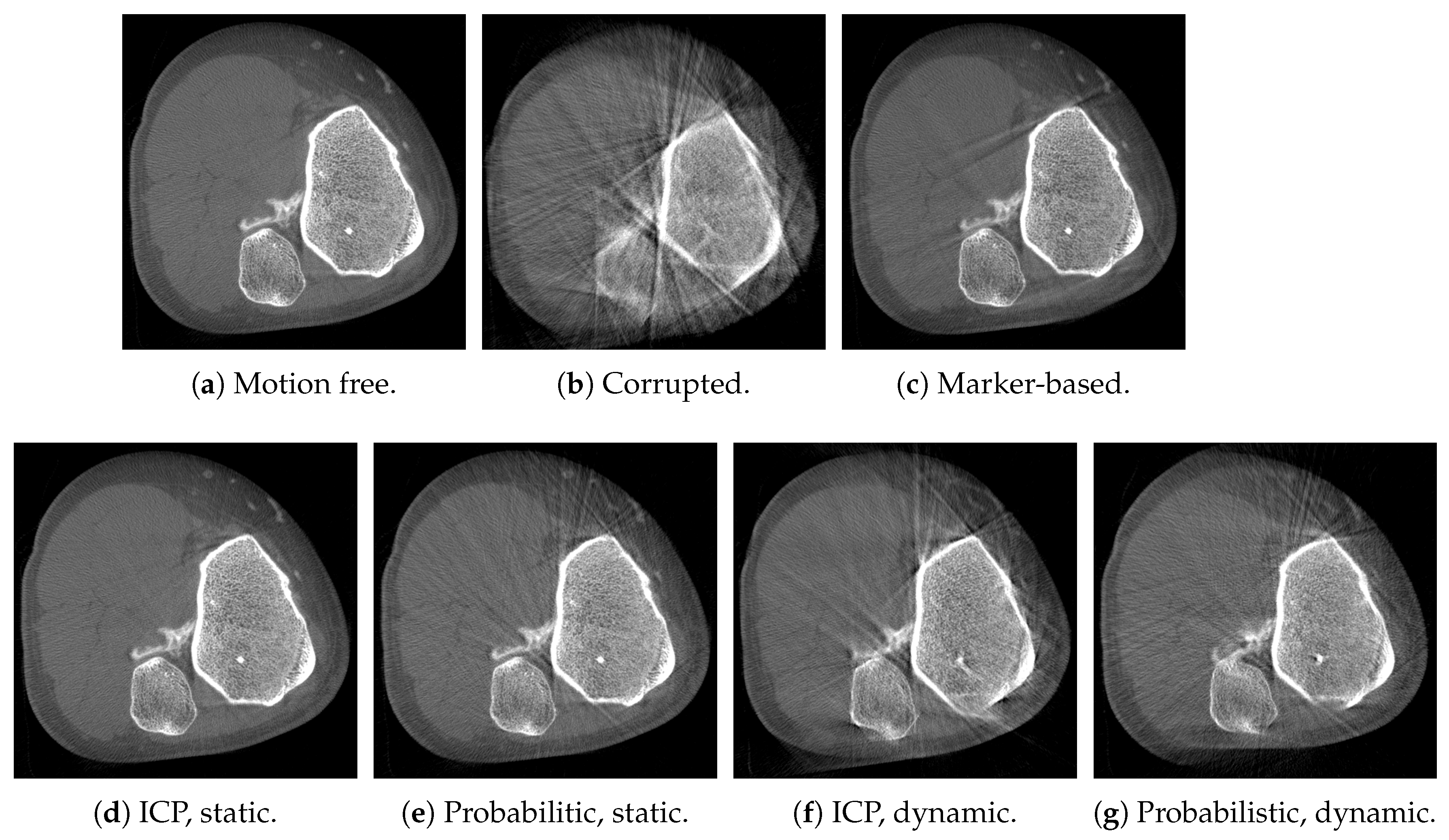
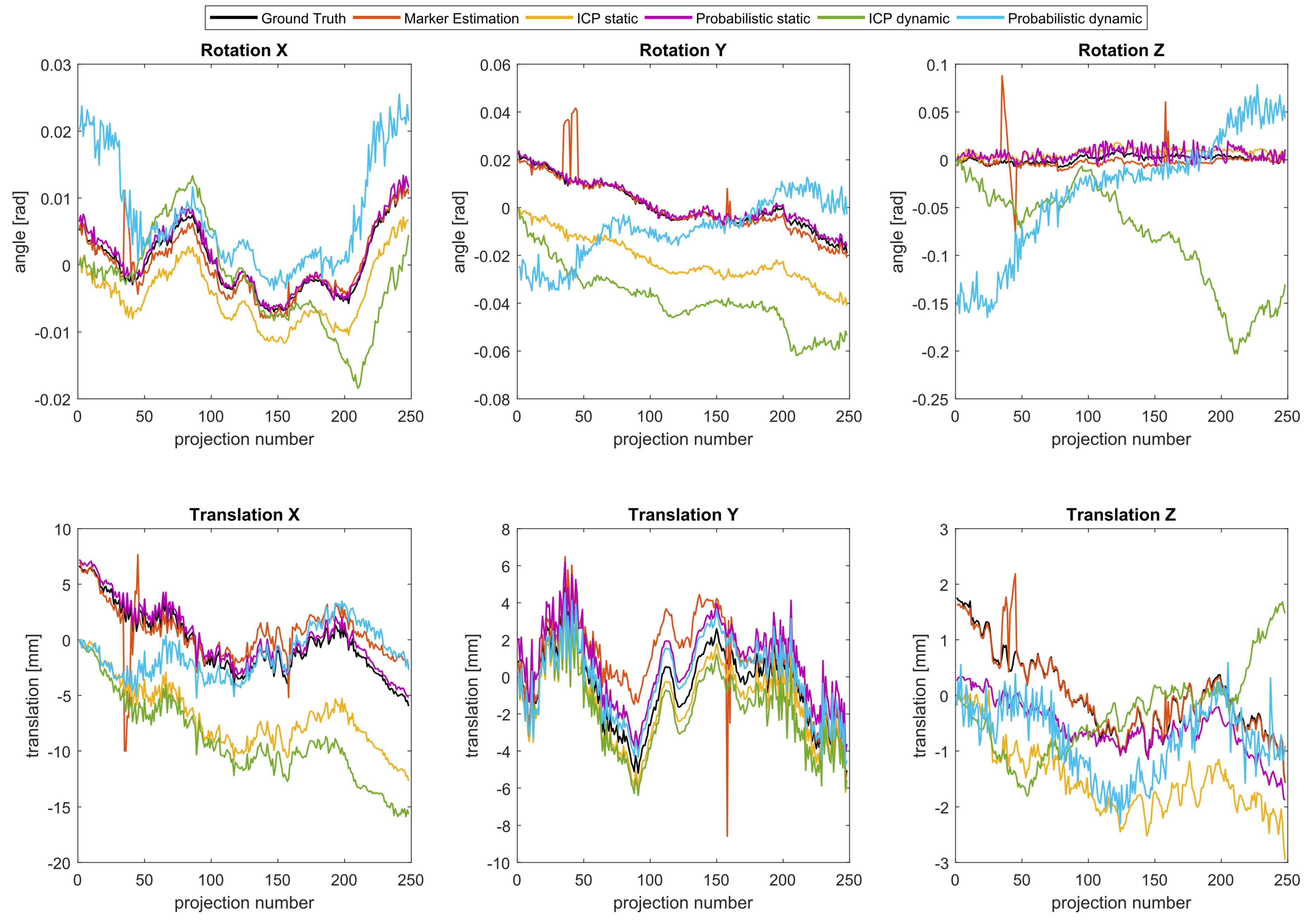
In order to compare the image quality of the results, the SSIM metric was computed. The SSIM quantifies the distortion between a reference and distorted image. In contrast other well know measures, like the Correlation Coefficient or the Root Mean Square Error, SSIM is motivated by incorporating more structural information that matches the human visual perception. This is done by normalizing the compared intensities with respect to their luminance and contrast. See [44] for more implementation details. To this end, all reconstructions have been registered to the motion free reference reconstruction using elastix [45]. This has been necessary, since the reconstruction can be shifted in the volume depending on the reference frame of the motion compensation.

3. Results

In Figure 4, we show axial slices of reconstruction results of dataset 1. In the first row, the motion free reference, the motion corrupted, and the marker-based corrected reconstructions are shown. Clearly, severe motion artifacts, such as streaks and blur, are present in the uncorrected reconstruction. Most of the artifacts were reduced substantially using the marker-based approach. However, distinct streaks remained in the volume that appear due to marker overlap in these views resulting in an inaccurate estimation. In the second row, the results using the point cloud registration approaches are shown: Figure 4d,e show the results of the static camera position, whereas Figure 4f,g show the results for the dynamic range camera trajectory. In all cases, there has been substantial improvement in the reconstructions relative to the uncompensated case. Visually, the best result were achieved with the ICP on the static dataset. Comparing the results of the dynamic scenario Figure 4f,g, a slightly better result has been achieved with the probabilistic approach. This might be due to the pair wise fashion of the ICP algorithm that could lead to a summation of the error and thus in a drift in the estimated motion signal.
This observation was endorsed by the results of the noise experiments, where the motion has been estimated on the point clouds with added noise. The results of this experiment are shown in Figure 5. Again, we compared the results of the ICP and the probabilistic approach: the two images on the left compare the results of the static camera position, while on the right the results achieved with the dynamic camera trajectory are shown. In both scenarios the probabilistic approach showed less streaks in the reconstructions, see Figure 5b,d. Nearly no difference between the noise free and the noisy dataset can be observed for this method.
In Figure 6, the estimated motion signals are shown for dataset 1. The estimated and reference rotations are shown in the top row, while the corresponding translations are shown in the bottom row. Note, that the x and y direction define the axial plane, whereas z is parallel to the rotation axis of the C-arm. The offset in the estimated signals resulted from the different references used by the optimization schemes of the registration methods. An offset in these motion signals compared to the ground truth leads to a shift in the volume, which is compensated by the subsequents registration of the volumes. Due to the cone-beam geometry, this shift can cause cone-beam artifacts. Starting with the marker-based estimation, one can observe heavy outliers in the estimated signals. These outliers resulted from views in which some of the fiducial markers overlapped with one another in the projection images. Consequently, this lead to incorrect correspondences and thus to errors in the estimated parameters. Apart from that, the marker-based method estimated the motion well. If we compare the ICP estimation with the estimation of the probabilistic registration, one can observe more noise in the estimation of the latter. Furthermore, it is noticeable that the least accurate component of the estimated translations has been the z-component. However, in the dynamic scenario the drawback of the ICP-based registration approach was evident: a drift of the signal due to the pair-wise nature of the algorithm can be observed. Errors in the estimation accumulated with each successive pair of views that were registered and ultimately, resulted in the drift observed towards the end of the scan (refer to Figure 6). This effect has been even more severe for the noise experiments.
After the qualitative assessment of the reconstruction quality and the estimated signals, we evaluated the SSIM metric for each reconstruction, relative to the motion free volumes, see Table 1. The quantitative values were in agreement with the visual impressions: all motion correction approaches improved the results compared to the uncorrected reconstruction. The best result has been achieved in the static scenario using the ICP approach, where a SSIM of 0.99 could me measured. This indicates that most of the motion could be recovered. For the dynamic scenario the probabilistic method outperformed the ICP and a SSIM of 0.97 could be achieved. However, in the dynamic case, none of range camera-based approaches achieved results comparable to the marker-based approach.
As it has been already visible in the shown reconstruction images, the influence of the noise in the data has effected the results of the ICP more compared to the probabilistic approach. According to the calculated SSIM, the noise did not influence the performance of the probabilistic approach, it remained the same for the static case and could even slightly improve for the dynamic scenario.
The reconstruction results for dataset 2 are shown in Figure 7. In general, the same observations as for dataset 1 can be observed: both proposed methods in both scenarios could improve the results compared to the uncorrected reconstruction. As in the first dataset, visually, the best result have been achieved using the ICP in the static scenario. The results got worse in the dynamic scenario. These observations match also with the SSIM values shown in Table 1.

4. Discussion

We presented a novel approach for tracking patient motion in C-arm CBCT acquisitions under weight-bearing conditions. We suggested to estimate motion using a range camera placed either on the floor or on the C-arm directly. In our proposed acquisition protocol, a range camera simultaneously observed the patient during the CBCT scan. After that, the acquired point clouds were registered resulting in motion estimates, which were then incorporated into the reconstruction. Compared to the state-of-the-art marker-based method, our method achieved comparable image quality without the need for marker placement. Although, only rigid body motion was estimated, we believe that using the dense surface information provided by the range camera, more complex deformation fields, accounting for non-rigid deformations (such as of the skin and muscles for example), may be estimated. The work presented in this paper is thus, a pre-cursor to subsequent work that will look to account for non-rigid deformations.
For the simulation study, point clouds and projections were simulated under realistic patient motion. Motion was estimated using two different point cloud registration approaches, namely: a pair wise point-to-plane ICP and a probabilistic group wise method. We validated our method on two different datasets qualitatively and quantitatively by calculating the SSIM metric. In most cases, our proposed method was able to recover the simulated patient motion well and was able to reduce motion artifacts noticeably. However, estimated rotation about the z axis in particular, was found to be more noisy. This can be explained by the shape of the knee that is cylindric with its axis aligned with the z axis. Rotation around this axis has no large influence on the cost function of the registration since there are too few features in this direction. Furthermore, the motion estimated by the group-wise method is also found to be more noisy than the results achieved by the ICP. We believe that this is due to the current implementation of this method: all point clouds are currently registered to a mean shape. Due to performance reasons and due to memory constraints, this mean shape contains fewer points than a single point cloud (1000 points used to define the mean shape, which correspond to 1000 components in the mixture model). This means, that less information is used in the actual registration step. The ICP, on the other hand, showed a slight drift in the estimated motion for the dynamic scenarios that resulted from its pair wise manner. Errors added up due the concatenation of the estimated transformations. This behavior might be even more distinct under realistic conditions, where noise could adversely affect the performance even more. This has also been proven in the noise experiments, where we showed that noise effects the ICP results more than the results obtained by the probabilistic approach. This will be further investigated in future work on real data.
Despite the encouraging results achieved in this study, the proposed method still has several limitations: (1) real data experiments have to be conducted in order to demonstrate its practical applicability. To this end, technical challenges such as cross calibration or synchronization of both systems have to be overcome [46,47]; (2) only three dimensional rigid motion was simulated and estimated that does not reflect realistic patient motion. Motion of human joints is a highly complex combination of multiple rigid body transformations of the bony and deformable displacements of the surrounding soft tissue. However, we believe that an approach using an RGBD camera that delivers dense depth and color information of the human knee, is able to recover such sophisticated displacements fields. Algorithms, such as a Simultaneous Localization and Mapping (SLAM) algorithms, could be adjusted to solve the motion estimation problem [48]. That could also improve the current results for the rotation estimation around the z axis in particular, since the use of color as additional information during registration could help improve results in this regard; (3) estimation of translation in the z direction is difficult. We believe that this is the result of the limited field of view of the range camera, which causes truncation of the point clouds in this direction. This might be addressed using a previously reported approach, which incorporates image based motion estimation to stabilize these results [49]; (4) evaluation on sensor noise and measurement accuracy has to be investigated. This is especially important when dealing with real depth data containing a high amount of noise and other physical artifacts. In real data experiments, range camera specific error sources such as intensity or temperature related errors, multi-path effect, outliers, or discontinuities in the depth estimation have to be expected [25]. This could be tackled by using more advanced depth cameras as proposed by Willomitzer et al. [50]. They propose a depth camera setup that can provide a high spatial resolution up to 300,000 points and an accuracy of 1/1000 of the distance measuring range; (5) the best results were achieved using the ICP algorithm in the static scenario. However, considering the practical applicability of the method, the more realistic and favored camera position is the dynamic one, since it requires a single calibration only, uses less space, and less occlusion is expected. However, the results achieved from the dynamic setup are not clinically satisfying yet. Despite these limitations, the presented work highlights the potential of range camera motion estimation for acquiring images of the knee under weight bearing conditions. In particular, we showed that estimating patient motion with a camera mounted on the C-arm is possible and image quality could be improved without the need of marker placement or a prior supine scan. This work enables future work on real data with more complex motion and facilitates the opportunities of novel acquisition setups.

Acknowledgments

This work was supported by the Research Training Group 1773 Heterogeneous Image Systems, funded by the German Research Foundation (DFG). Further, the authors acknowledge funding support from NIH 5R01AR065248-03 and NIH Shared Instrument Grant No. S10 RR026714 supporting the zeego@StanfordLab. The authors gratefully acknowledge funding of the Erlangen Graduate School in Advanced Optical Technologies (SAOT) in the framework of the German excellence initiative.

Author Contributions

Bastian Bier, Nishant Ravikumar, and Mathias Unberath wrote the main part of the paper. Bastian Bier and Nishant Ravikumar designed the experiments. Bastian Bier and Mathias Unberath analyzed the data. Garry Gold and Rebecca Fahrig provided the projection images. Marc Levenston, Rebecca Fahrig, and Andreas Maier provided expertise through intense discussion. All authors reviewed the paper.

Conflicts of Interest

Rebecca Fahrig is now with Siemens Healthcare GmbH. No funding of Siemens has been received for this study.

Abbreviations

The following abbreviations are used in this manuscript:
CBCTcone-beam computed tomography
CTcomputed tomography
ICPIterative Closest Point
SSIMStructural Similarity
PETpositron emission tomography
SPECTsingle-photon emission computed tomography
HdMMhybrid mixture model

References

  1. Choi, J.H.; Maier, A.; Keil, A.; Pal, S.; McWalter, E.J.; Beaupré, G.S.; Gold, G.E.; Fahrig, R. Fiducial marker-based correction for involuntary motion in weight-bearing C-arm CT scanning of knees. II. Experiment. Med. Phys. 2014, 41, 061902. [Google Scholar] [CrossRef] [PubMed]
  2. Carrino, J.A.; Al Muhit, A.; Zbijewski, W.; Thawait, G.K.; Stayman, J.W.; Packard, N.; Senn, R.; Yang, D.; Foos, D.H.; Yorkston, J.; et al. Dedicated cone-beam CT system for extremity imaging. Radiology 2014, 270, 816–824. [Google Scholar] [CrossRef] [PubMed]
  3. Powers, C.M.; Ward, S.R.; Fredericson, M. Knee Extension in Persons With Lateral Subluxation of the Patella: A Preliminary Study. J. Orthop. Sports Phys. Ther. 2013, 33, 677–685. [Google Scholar] [CrossRef] [PubMed]
  4. Maier, A.; Choi, J.H.; Keil, A.; Niebler, C.; Sarmiento, M.; Fieselmann, A.; Gold, G.; Delp, S.; Fahrig, R. Analysis of vertical and horizontal circular C-arm trajectories. Proc. SPIE Med. Imaging 2011, 7961, 796123. [Google Scholar] [CrossRef]
  5. Choi, J.H.; Muller, K.; Hsieh, S.; Maier, A.; Gold, G.; Levenston, M.; Fahrig, R. Over-exposure correction in knee cone-beam CT imaging with automatic exposure control using a partial low dose scan. Proc. SPIE Med. Imaging 2016, 9783, 97830L. [Google Scholar]
  6. Zbijewski, W.; De Jean, P.; Prakash, P.; Ding, Y.; Stayman, J.W.; Packard, N.; Senn, R.; Yang, D.; Yorkston, J.; Machado, A.; et al. A dedicated cone-beam CT system for musculoskeletal extremities imaging: Design, optimization, and initial performance characterization. Med. Phys. 2011, 38, 4700. [Google Scholar] [CrossRef] [PubMed]
  7. Herbst, M.; Schebesch, F.; Berger, M.; Choi, J.H.; Fahrig, R.; Hornegger, J.; Maier, A. Dynamic detector offsets for field of view extension in C-arm computed tomography with application to weight-bearing imaging. Med. Phys. 2015, 42, 2718–2729. [Google Scholar] [CrossRef] [PubMed]
  8. Maier, J.; Black, M.; Bonaretti, S.; Bier, B.; Eskofier, B.; Choi, J.H.; Levenston, M.; Gold, G.; Fahrig, R.; Maier, A. Comparison of Different Approaches for Measuring Tibial Cartilage Thickness. J. Integr. Bioinform. 2017, 14, 1–10. [Google Scholar] [CrossRef] [PubMed]
  9. Siemens Healthcare GmbH. Siemens SOMATOM Definition Flash Brochure. Available online: https://static.healthcare.siemens.com/siemens_hwem-hwem_ssxa_websites-context-root/wcm/idc/groups/public/@global/@imaging/@ct/documents/download/mdaw/mzcz/~edisp/ct_ws_somatom_definition_flash_international-00292513.pdf (accessed on 5 January 2018).
  10. Unberath, M.; Aichert, A.; Achenbach, S.; Maier, A. Consistency-based respiratory motion estimation in rotational angiography. Med. Phys. 2017, 44, e113–e124. [Google Scholar] [CrossRef] [PubMed]
  11. Sonke, J.J.; Zijp, L.; Remeijer, P.; van Herk, M. Respiratory correlated cone beam CT. Med. Phys. 2005, 32, 1176–1186. [Google Scholar] [CrossRef] [PubMed]
  12. Hansis, E.; Schäfer, D.; Dössel, O.; Grass, M. Projection-based motion compensation for gated coronary artery reconstruction from rotational X-ray angiograms. Phys. Med. Biol. 2008, 53, 3807. [Google Scholar] [CrossRef] [PubMed]
  13. Ouadah, S.; Stayman, J.W.; Gang, G.J.; Ehtiati, T.; Siewerdsen, J.H. Self-calibration of cone-beam CT geometry using 3D–2D image registration. Phys. Med. Biol. 2016, 61, 2613–2632. [Google Scholar] [CrossRef] [PubMed]
  14. Choi, J.H.; Fahrig, R.; Keil, A.; Besier, T.F.; Pal, S.; McWalter, E.J.; Beaupré, G.S.; Maier, A. Fiducial marker-based correction for involuntary motion in weight-bearing C-arm CT scanning of knees. Part I. Numerical model-based optimization. Med. Phys. 2014, 41, 061902. [Google Scholar] [CrossRef] [PubMed]
  15. Berger, M.; Forman, C.; Schwemmer, C.; Choi, J.H.; Müller, K.; Maier, A.; Hornegger, J.; Fahrig, R. Automatic Removal of Externally Attached Fiducial Markers in Cone Beam C-arm CT. In Bildverarbeitung für die Medizin; Springer: Berlin, Germany, 2014; pp. 168–173. [Google Scholar]
  16. Müller, K.; Berger, M.; Choi, J.; Maier, A.; Fahrig, R. Automatic Motion Estimation and Compensation Framework for Weight-bearing C-arm CT scans using Fiducial Markers. In Proceedings of the World Congress on Medical Physics and Biomedical Engineering, Toronto, ON, Canada, 7–12 June 2015; pp. 58–61. [Google Scholar]
  17. Müller, K.; Berger, M.; Choi, J.h.; Datta, S.; Gehrisch, S.; Moore, T.; Marks, M.P.; Maier, A.K.; Fahrig, R. Fully Automatic Head Motion Correction for Interventional C-arm Systems using Fiducial Markers. In Proceedings of the 13th Fully Three-Dimensional Image Reconstruction in Radiology and Nuclear Medicine, Newport, RI, USA, 1–4 June 2015; pp. 534–537. [Google Scholar]
  18. Syben, C.; Bier, B.; Berger, M.; Aichert, A.; Fahrig, R.; Gold, G.; Levenston, M.; Maier, A. Joint Calibration and Motion Estimation in Weight-Bearing Cone-Beam CT of the Knee Joint Using Fiducial Markers. In Proceedings of the 2017 IEEE 14th International Symposium on Biomedical Imaging (ISBI 2017), Melbourne, Australia, 18–21 April 2017; pp. 494–497. [Google Scholar]
  19. Unberath, M.; Choi, J.H.; Berger, M.; Maier, A.; Fahrig, R. Image-based compensation for involuntary motion in weight-bearing C-arm cone-beam CT scanning of knees. Proc. SPIE Med. Imaging 2015, 9413, 94130D. [Google Scholar]
  20. Sisniega, A.; Stayman, J.; Yorkston, J.; Siewerdsen, J.; Zbijewski, W. Motion compensation in extremity cone-beam CT using a penalized image sharpness criterion. Phys. Med. Biol. 2017, 62, 3712. [Google Scholar] [CrossRef] [PubMed]
  21. Berger, M.; Müller, K.; Aichert, A.; Unberath, M.; Thies, J.; Choi, J.H.; Fahrig, R.; Maier, A. Marker-free motion correction in weight-bearing cone-beam CT of the knee joint. Med. Phys. 2016, 43, 1235–1248. [Google Scholar] [CrossRef] [PubMed]
  22. Aichert, A.; Wang, J.; Schaffert, R.; Dörfler, A.; Hornegger, J.; Maier, A. Epipolar Consistency in Fluoroscopy for Image-Based Tracking. Proc. BMVC 2015, 82.1–82.10. [Google Scholar] [CrossRef]
  23. Berger, M.; Xia, Y.; Aichinger, W.; Mentl, K.; Unberath, M.; Aichert, A.; Riess, C.; Hornegger, J.; Fahrig, R.; Maier, A. Motion compensation for cone-beam CT using Fourier consistency conditions. Phys. Med. Biol. 2017, 62, 7181–7215. [Google Scholar] [CrossRef] [PubMed]
  24. Bier, B.; Aichert, A.; Felsner, L.; Unberath, M.; Levenston, M.; Gold, G.; Fahrig, R.; Maier, A. Epipolar Consistency Conditions for Motion Correction in Weight-Bearing Imaging. In Bildverarbeitung für Die Medizin; Springer: Berlin/Heidelberg, Germany, 2017; pp. 209–214. [Google Scholar]
  25. Bauer, S.; Seitel, A.; Hofmann, H.G.; Blum, T.; Wasza, J.; Balda, M.; Meinzer, H.P.; Navab, N.; Hornegger, J.; Maier-Hehn, L. Real-Time Range Imaging in Health Care: A Survey. In Time-of-Flight and Depth Imaging. Sensors, Algorithms, and Applications; Lecture Notes in Computer Science; Springer: Berlin/Heidelberg, Germany, 2013; Volume 8200, pp. 228–254. [Google Scholar]
  26. Fischer, M.; Fuerst, B.; Lee, S.C.; Fotouhi, J.; Habert, S.; Weidert, S.; Euler, E.; Osgood, G.; Navab, N. Preclinical usability study of multiple augmented reality concepts for K-wire placement. Int. J. Comput. Assist. Radiol. Surg. 2016, 11, 1007–1014. [Google Scholar] [CrossRef] [PubMed]
  27. Navab, N.; Bani-Kashemi, A.; Mitschke, M. Merging visible and invisible: Two Camera-Augmented Mobile C-arm (CAMC) applications. In Proceedings of the 2nd IEEE and ACM International Workshop on Augmented Reality, San Francisco, CA, USA, 20–21 October 1999; pp. 134–141. [Google Scholar]
  28. McNamara, J.E.; Pretorius, P.H.; Johnson, K.; Mukherjee, J.M.; Dey, J.; Gennert, M.A.; King, M.A. A flexible multicamera visual-tracking system for detecting and correcting motion-induced artifacts in cardiac SPECT slices. Med. Phys. 2009, 36, 1913–1923. [Google Scholar] [CrossRef] [PubMed]
  29. Geimer, T.; Unberath, M.; Taubmann, O.; Bert, C.; Maier, A. Combination of Markerless Surrogates for Motion Estimation in Radiation Therapy. In Proceedings of the Computer Assisted Radiology and Surgery (CARS) 2016: 30th International Congress and Exhibition, Heidelberg, Germany, 21–25 June 2016; pp. 59–60. [Google Scholar]
  30. Fotouhi, J.; Fuerst, B.; Wein, W.; Navab, N. Can real-time RGBD enhance intraoperative Cone-Beam CT? Int. J. Comput. Assist. Radiol. Surg. 2017, 12, 1211–1219. [Google Scholar] [CrossRef] [PubMed]
  31. Bier, B.; Unberath, M.; Geimer, T.; Maier, J.; Gold, G.; Levenston, M.; Fahrig, R.; Maier, A. Motion Compensation Using Range Imaging in C-Arm Cone-Beam CT. In Proceedings of the Annual Conference on Medical Image Understanding and Analysis, Edinburgh, UK, 11–13 July 2017; pp. 561–570. [Google Scholar]
  32. Bellekens, B.; Spruyt, V.; Weyn, M. A Survey of Rigid 3D Pointcloud Registration Algorithms. In Proceedings of the AMBIENT 2014, The Fourth International Conference on Ambient Computing, Applications, Services and Technologies, Rome, Italy, 24–28 August 2014; pp. 8–13. [Google Scholar]
  33. Ravikumar, N.; Gooya, A.; Frangi, A.F.; Taylor, Z.A. Generalised Coherent Point Drift for Group-Wise Registration of Multi-dimensional Point Sets. In Proceedings of the International Conference on Medical Image Computing and Computer-Assisted Intervention, Quebec City, QC, Canada, 10–14 September 2017; pp. 309–316. [Google Scholar]
  34. Habert, S.; Gardiazabal, J.; Fallavollita, P.; Navab, N. RGBDX: First design and experimental validation of a mirror-based RGBD X-ray imaging system. In Proceedings of the 2015 IEEE International Symposium on Mixed and Augmented Reality, Fukuoka, Japan, 29 September–3 October 2015; pp. 13–18. [Google Scholar]
  35. Zeng, G.L. Medical Image Reconstruction: A Conceptual Tutorial; Springer: New York, NY, USA, 2010. [Google Scholar]
  36. Strobel, N.K.; Heigl, B.; Brunner, T.M.; Schütz, O.; Mitschke, M.M.; Wiesent, K.; Mertelmeier, T. Improving 3D Image Quality of X-ray C-Arm Imaging Systems by Using Properly Designed Pose Determination Systems for Calibrating the Projection Geometry. Proc. SPIE Med. Imaging 2003, 5030, 943–954. [Google Scholar]
  37. Hartley, R.I.; Zisserman, A. Multiple View Geometry in Computer Vision, 2nd ed.; Cambridge University Press: Cambridge, UK, 2004. [Google Scholar]
  38. Wasenmüller, O.; Stricker, D. Comparison of Kinect v1 and v2 Depth Images in Terms of Accuracy and Precision. In Proceedings of the Asian Conference on Computer Vision, Taipei, Taiwan, 20–24 November 2016; pp. 34–45. [Google Scholar]
  39. Peter, F.; Placht, S.; Balda, M.; Schaller, C.; Hofmann, H.; Maier, A.; Riess, C. A Comparative Error Analysis of Current Time-of-Flight Sensors. IEEE Trans. Comput. Imaging 2015, 2, 27–41. [Google Scholar]
  40. Maier, A.; Hofmann, H.G.; Berger, M.; Fischer, P.; Schwemmer, C.; Wu, H.; Müller, K.; Hornegger, J.; Choi, J.H.; Riess, C.; et al. CONRAD—A software framework for cone-beam imaging in radiology. Med. Phys. 2013, 40, 111914. [Google Scholar] [CrossRef] [PubMed]
  41. Ravikumar, N.; Gooya, A.; Çimen, S.; Frangi, A.F.; Taylor, Z.A. A multi-resolution t-mixture model approach to robust group-wise alignment of shapes. In Proceedings of the International Conference on Medical Image Computing and Computer-Assisted Intervention, Quebec City, QC, Canada, 10–14 September 2016; pp. 142–149. [Google Scholar]
  42. Feldkamp, L.A.; Davis, L.C.; Kress, J.W. Practical cone-beam algorithm. J. Opt. Soc. Am. A 1984, 1, 612. [Google Scholar] [CrossRef]
  43. Segars, W.P.; Sturgeon, G.; Mendonca, S.; Grimes, J.; Tsui, B.M.W. 4D XCAT phantom for multimodality imaging research. Med. Phys. 2010, 37, 4902. [Google Scholar] [CrossRef] [PubMed]
  44. Wang, Z.; Bovik, A.C.; Sheikh, H.R.; Simoncelli, E.P. Image quality assessment: From error visibility to structural similarity. IEEE Trans. Image Process. 2004, 13, 600–612. [Google Scholar] [CrossRef] [PubMed]
  45. Stefan Klein and Marius Staring and Keelin Murphy and Max A. Viergever and Josien P.W. Pluim. elastix: A toolbox for intensity-based medical image registration. IEEE Trans. Med. Imaging 2010, 29, 196–205. [Google Scholar]
  46. Rausch, J.; Maier, A.; Fahrig, R.; Choi, J.H.; Hinshaw, W.; Schebesch, F.; Haase, S.; Wasza, J.; Hornegger, J.; Riess, C. Kinect-based correction of overexposure artifacts in knee imaging with C-Arm CT systems. Int. J. Biomed. Imaging 2016, 2016. [Google Scholar] [CrossRef] [PubMed]
  47. Chun, S.; Bernhard, L.; Fotouhi, J.; Fischer, M.; Osgood, G.; Navab, N. Calibration of RGBD camera and cone-beam CT for 3D intra-operative mixed reality visualization. Int. J. Comput. Assist. Radiol. Surg. 2016, 11, 967–975. [Google Scholar]
  48. Endres, F.; Hess, J.; Engelhard, N.; Sturm, J.; Cremers, D.; Burgard, W. An evaluation of the RGB-D SLAM system. In Proceedings of the 2012 IEEE International Conference on Robotics and Automation, Saint Paul, MN, USA, 14–18 May 2012; pp. 1691–1696. [Google Scholar]
  49. Bier, B.; Unberath, M.; Geimer, T.; Ravikumar, N.; Gold, G.; Fahrig, R.; Maier, A. Fusing Motion Estimates for CBCT reconstruction. In Proceedings of the 2017 IEEE Nuclear Science Symposium and Medical Imaging Conference (IEEE NSS/MIC 2017), Atlanta, GA, USA, 21–28 October 2017. [Google Scholar]
  50. Willomitzer, F.; Häusler, G. Single-shot 3D motion picture camera with a dense point cloud. Opt. Express 2017, 25, 23451–23464. [Google Scholar] [CrossRef] [PubMed]
Figure 1. Schematic scene of the acquisition scenario. During scanning, the C-arm rotates around the object and acquires projections. At the same time, a range camera observes the scene. Possible camera positions investigated in this work are either dynamic (a) or static (b).
Jimaging 04 00013 g001
Figure 2. Simulated projection image (a) with its corresponding point cloud (b).
Jimaging 04 00013 g002
Figure 3. Method work flow: point clouds were used to estimate patient motion, which is then used for reconstruction.
Jimaging 04 00013 g003
Figure 4. Reconstruction results of dataset 1: axial slices of the motion free reference volume (a); the motion corrupted (b); the marker-based corrected (c); and the proposed methods (dg).
Jimaging 04 00013 g004
Figure 5. Reconstruction results of dataset 1 achieved with noisy point clouds.
Jimaging 04 00013 g005
Figure 6. Estimated motion signals. The rotation parameters are Euler angles calculated from the estimated rotation matrices in order to simplify the presentation.
Jimaging 04 00013 g006
Figure 7. Reconstruction results of dataset 2: axial slices of the motion free reference volume (a); the motion corrupted (b); the marker-based corrected (c); and the proposed methods (dg).
Jimaging 04 00013 g007
Table 1. Structural Similarity (SSIM) results of the reconstructed images for dataset 1 and dataset 2.
MethodDataset 1with NoiseDataset 2
Uncorrected0.93-0.81
Marker-based [1]0.98-0.98
ICP static0.990.950.99
Probabilistic static0.980.980.99
ICP dynamic0.940.940.95
Probabilistic dynamic0.960.970.94

