Quad-Bike Operational Instability

Honorary Senior Fellow in Agricultural Engineering, Department of Infrastructure Engineering, University of Melbourne, Parkville, Victoria 3052, Australia
Safety 2017, 3(2), 15; https://doi.org/10.3390/safety3020015
Submission received: 13 December 2016
/
Revised: 14 May 2017
/
Accepted: 24 May 2017
/
Published: 31 May 2017
(This article belongs to the Collection Terrain and Off-Highway Vehicle Safety)
Abstract
:The stake-holders in the quad-bike (QB) industry in Australia have failed to reach a satisfactory resolution of the present impasse that exists with respect to the causes and mitigation of the trauma suffered by riders due to QB instability. In an effort to provide purchasers with data enabling them to discriminate between safer and less safe machines, static longitudinal and lateral tests have been conducted by various interested parties; quasi-static lateral tests have also been conducted under some operational conditions. It is argued that while these static tests are valid, under many operating conditions QBs will not reach such unstable slopes due to poor traction. Further, these tests do not include the quasi-static and dynamic factors which also influence the processes associated with operational instability. For these reasons, the static tests do not provide an adequate basis for discrimination between safer and less safe machines.
1. Introduction
The widespread use of quad bikes (QBs) or All-terrain Vehicles (ATVs) in agriculture, industry and recreation suggests that they meet the need for light, mobile transport for both people and goods. However, the number of trauma cases associated with their use, the inability of the stake-holders (manufacturers, dealers, users and advisors) to reduce these, and the stand-off between these parties suggests that a new approach is called for.
The context of this paper may therefore be seen in the following:
- The trauma and death that occurs annually with QBs in Australia. In the period 2001–2010, there were 124 fatal QB-related incidents in Australia. Two-thirds of these fatalities occurred on farms, with about half involving roll-overs sideways (Lower et al.) [1].
- The circumstances of these incidents are as varied as the riders who experience them—anybody from mature adults with much experience but little formal rider education and varied intuition, to young and inexperienced although perhaps educated riders with ‘gung-ho’ attitudes.
- The failure of most QB manufacturers to provide any roll-over, tip-up or pitch-over protection. This is perhaps because the risk of instability is not seen as an inherent problem in the design and operation of most machines used in off-road environments. Rather, it is considered that the problems can be avoided, or at least mitigated, by seeking evolutionary modifications that would make the machine safer, and by providing more education and protective items for the rider.
- The need for the design and promotion of commercial Roll-over Protective Structures (ROPS) as part of the original design, as based on the well-established principle of energy absorption use within the structure to mitigate the impact and resulting trauma.
- The failure of Governments to mandate the fitting of ROPS. The wide diversity of opinions between the stake-holders leaves Governments unable, perhaps more on political than policy grounds, to mandate the fitting of ROPS to all (or most) QBs.
Or is it that, notwithstanding the widespread interest, the problem has not been adequately defined, nor the way ahead clarified? The trauma noted above results largely from the instability of QBs under the action of static and dynamic forces, particularly when travelling on slopes. The static instability angles, which represent the simplest measures of instability, have been measured in static tests by Grzebieta et al. at the University of New South Wales (UNSW) and are used to rank QBs according to their propensity to become unstable [2].
However, the present paper, which is based on the results of that work, suggests that in many situations and particularly on agricultural soils, QBs will not be able to reach or operate on such slopes due to (rotational) wheel-slip (in the longitudinal direction) or side-slip (in the lateral direction). Further, the simple static angles do not consider the quasi-static and dynamic effects that also influence operational instability. It will be concluded that for the above reasons, the simple static angles are not a suitable basis for ranking QBs according to their operational instability, and are unlikely to provide a valid basis for the selection of safer machines.
2. Quad Bikes as Off-Road Machines
Machines such as tractors and QBs are in a class known as ‘off-road’ vehicles—a class which also includes military and earth-moving machines. These all differ from road vehicles in that they operate at relatively low speeds on unprepared surfaces, often under relatively heavy draw-bar or carried loads. Notwithstanding these differences, they have much in common, not least of which is the need for all-round protection of the rider in the case of instability.
Their operation and performance is dependent on the land-forms that they traverse, on the properties of the surface (soil) on which they operate, and on the attachment and operation of any implements. Tractors and QBs mainly work on ‘agricultural’, ‘organic’, or ‘top’ soils; although these soils are often in a compacted condition, they are ‘weak’ and hence ‘fail’, causing immobility in the process generally known as ‘wheel-slip’.
As a sub-class, QBs usually work in un- or lightly-loaded conditions, often travel faster than most other vehicles in their class, and operate over more variable land-forms. They are also relatively light-weight and the presence of the rider and any carried load influences the height of the centre of gravity (CoG), which may influence (to a small degree, for good or ill) the longitudinal and lateral position. All of these factors, to a greater or lesser degree, influence the vehicle’s stability profile.
Impacts of such vehicles with structures and other vehicles are not uncommon and generally involve humans in some way. Hence, through their overall design, we seek to minimise the damage to the areas suffering the actual impact, and in particular to the humans involved.
In the crashes of road vehicles, impacts are usually with other vehicles or roadside structures. However, with off-road vehicles such as tractors and QBs, the initial impact is often with the ground in a longitudinal ‘tip-up’ or a lateral ‘roll-over’. Without some form of structural protection, such as that of so-called ‘safety frames’ which are now common on tractors, the driver is largely unprotected and is often injured or even killed.
Of course, changes that could improve the basic static stability are already well known—lower the CoG and widen the wheel track. These could be adopted, but they would involve significant design changes such as lowering the ground clearance and increasing the operational width; both are seen as undesirable, if not unacceptable.
3. QB Operation and Instability
QB operation depends on the tractive capacity of the wheel/surface interface in the tangential direction to drive the QB forward or rearward and in the transverse direction, allowing the QB to operate on slopes and in cornering.
The simple theoretical analysis and tilt-table tests, though valid, only show the static stability of the QB with wheels locked to prevent rotation in tip-up tests, and with some arrangement to prevent the tyres slipping in both tip-up and roll-over tests. This is quite inadequate to represent the operational conditions under which most QB instability occurs.
This operational instability, which should ideally be the basis for the selection of the most stable machine, is highly complex and dynamic. It depends not only on the dimensional parameters of the machine, but also on its inertial parameters defined by its mass, for linear effects, and its mass moment of inertia for rotational effects. The latter are superimposed on the static and quasi-static parameters, giving an overall process that is difficult to model in the laboratory or on the computer.
In addition to this complexity in the behaviour of the QB as a machine, we also need to recognise the complexity of the interaction of the machine with the surface on which it is operating. That interaction involves both the normal (perpendicular) reaction and the shearing (tangential) reaction on the wheel/soil interface.
The simple, non-dimensional measure of the strength of the soil is the ‘traction coefficient’ (analogous to the ‘friction coefficient’ between dry surfaces); it is based on the ratio of the maximum shearing force (strength) of the soil to the corresponding normal force and is usually given the symbol tan θ. The values for typical agricultural soils are shown in Figure 1 and Figure 3 [3].
The normal operation of the QB occurs if the strength of the soil/wheel interface exceeds the forces imposed on it by the QB; it thus proceeds on its way. If not, the wheels of the QB may slip rotationally or slide sideways; hence (in static or quasi-static terms), the QB will not reach or remain on the slope. However, assuming the wheels do not slip or slide, if the forces on the chassis from the normal wheel reactions and the engine torque are sufficient, the QB may tip up or roll over.
In the present paper, the significance of the static angles for rearward and lateral instability of the eight work QBs as presented by Grzebieta et al. will be considered relative to the limitation that traction conditions impose on the operation of QBs on slopes [2]. The further limitation of quasi-static and dynamic factors, which also influence the operational instability, are then considered.
The control of forward motion down a slope depends on the availability of engine and wheel braking, which in turn depends on which wheels are braked and the strength of the wheel/soil interface. Hence, the QB may brake, slide bodily with locked wheels, or run out of control and perhaps tip when it hits an immovable object or runs down a steeper part of the slope. Its instability will thus be a much more dynamic process than the other modes and, because it requires data that is not available, it will not be considered further.
4. Longitudinal Rearward Operational Instability
A more detailed analysis of a QB in a condition of impending rearward longitudinal instability is presented in Appendix A as an extension of the simple analysis given by Macmillan [4]. It gives expressions for the slopes that are required to bring the QB to operational instability under static and quasi-static conditions.
It should be noted that a rear wheel drive vehicle will not tip as a rigid body (as the static tests might suggest); rather, the chassis will tip about the rear axle, purely as a result of the moment on it that acts as a reaction to the moment on the wheels, plus any other forces with a moment about the rear axle.
The former moment arises from all the static and quasi-static forces resisting the motion of the vehicle up the slope, viz:
- static: the component of the weight down the slope;
- quasi-static: the rolling resistance of the wheels and any drawbar pull (the latter is not included here).
4.1. Static Effects
As shown in Figure A1, Appendix A, when the front wheels leave the ground, the angle of slope α for impending static instability, represented by tan α, is given by the ratio of the distance of the CoG in front of the rear axle (xg) to the height of the CoG perpendicular to the ground surface (r, radius of the wheel + yg, the height of the CoG above the rear axle).
This definition is identical to the ‘Tilt Table Ratio’ as defined and measured in the UNSW tests and analysed below [2]. The ranges of the slope values (plotted as tan α) measured under five loading conditions (shown in Table A1, Appendix C as cargo capacity) for the eight work QBs with locked wheels and a dummy rider (where shown) are plotted in Figure 1.
This Figure shows that for most loading conditions, the slope (tan α), for rearward static instability exceeds the traction coefficient (tan θ). Hence the wheels will slip and the QB will never reach these angles; using these to choose a more stable make will not be useful.
Further, this Figure also shows that the variation in the rear tip-up angles within the eight QBs is some ±10% of the mean values—a result that is not surprising since the QBs all have similar features and layout. While this data shows real differences, it is arguable whether these are large enough to have a significant influence on purchasers in their choice between safer and less safe vehicles. If they are not, it is unlikely to have a significant effect on the evolution of the designs towards safer vehicles.
Interestingly, what the graph does show is the significant effect of the presence of the rider and the loading arrangements on static instability. The effect of load-position is about the same magnitude as the variation between the most stable and least stable machines. In other words, the least stable machine with front load is about as stable as the most stable machine with rear load; tan α = 0.8. A QB with a front load will be as, or more stable, than any QB with a rear load.
Whether active riding will have a significant effect on the static stability will be determined by the ability of the rider to move their CoG far enough forward to make a significant difference to the weight distribution.
4.2. Quasi-Static Effects
As shown in Appendix A, when the contribution of the rolling resistance of the wheels to the moment on the chassis is included (by the introduction of the term x’), the lower and more realistic tipping angle tan α’ is given by:
The rolling resistance (represented by x’) will be a function of:
- the weight of the QB: ±30% for the eight work machines tested by UNSW as shown Table A1;
- the type of tyres;
- the condition (particularly the deformability) of the soil surface.
In operation, each of these factors will have the effect of altering the rear tip-up angle; this will be confounded with the static effect. In other words, machines with greater rolling resistance and hence greater moment on the chassis may have greater operational instability (lower tan α’ values); this is despite having a higher static stability as shown by higher tan α values.
Weak, deformable soils may therefore have two opposing effects—a high rolling resistance, hence a high engine torque and tendency to tip up, but also a greater tendency for the wheels to slip. This latter effect, of course, is the saving feature of many off-road vehicles where the traction conditions are not good enough to implicate vehicle instability. Again, this illustrates why the static analysis is inadequate as a measure of operational instability.
4.3. Dynamic Effects
On the basis of the above discussion of static and quasi-static effects, it is clear that many QBs may never reach an unstable slope. So, how do they come to instability? The process is much more complex than the simple theoretical analysis suggests, and more dynamic than the static tilt-table illustrates.
The QB chassis may also be subject to dynamic effects such as:
- a reactive moment on the chassis, arising from:
- ○
- a linear acceleration of the chassis up the slope;
- ○
- a rotational acceleration of the driving wheels.
- an impulse on the front wheels, perpendicular to the slope, having a moment about the rear axle.
Given these inertial effects, the instability of a QB may be influenced not only by the static and quasi-static effects discussed above, but also by its mass and mass moment-of-inertia about the rear axle. However, the mass moment of inertia values are not known; thus, for the purposes of this argument, we must, pro tem, seek a surrogate variable that will illustrate the differences between the various QBs. Using the variables shown in Figure A1, a plot of M versus the parameter M. [(xg2 + yg2)] (which provides a measure of the moment of inertia about the rear axle,) gave a significant linear and highly correlated relationship between these two variables (correlation coefficient 0.98); this justifies the use of mass for this argument.
Figure 2 shows the variation in the slope (tan α) for rear tip-up plotted against stand-alone mass for the eight work QBs tested by UNSW. A similar result is obtained if, for example, maximum operating mass is used.
Figure 2 also shows that the work QBs, which have a ±10% variation in static longitudinal instability angle, tan α, could be expected to have a ±30% variation in mass moment of inertia. Inertia effects will therefore be confounded with the static effects, confirming what is already known—operational instability is a complex function of both QB design and operation.
While tan α is a valid and suitable parameter to determine static rear longitudinal instability, the small variation between makes will not provide a significant guide to operational instability. Further, because the actual tip-up process also includes significant quasi-static and dynamic factors, we must conclude that the static values will not provide a reliable basis for discrimination between less stable and more stable QBs.
5. Lateral Instability
In terms of lateral instability, the QB will act much more like a rigid body than it does for longitudinal instability. Hence, the two static requirements for instability are as follows:
- (i)
- The component of the (static) weight down the slope, plus any (effectively quasi-static) forces through the CoG (such as the centrifugal ‘force’ during turning) and any dynamic inertial forces arising from sliding impact on a resisting object, must fall outside the base.
- (ii)
- The lateral force at the wheel/surface contact patch must not exceed the shearing strength (represented by tan γ, the ‘lateral coefficient’,) at that interface.
5.1. Static and Quasi-Static Effects
In driving across a slope, the above requirement in (i) is well understood from basic mechanics of a rigid body and, to a first order, is not influenced by the mechanics of the drive train.
As shown in Appendix B, for a QB with track width t and height of CoG, (r + yg), the angle of impending instability by rolling over (γ), represented by the upper wheels leaving the ground, is given by:
This definition is identical to the ‘Static Stability Factor’ as defined by UNSW [2].
Figure 3 shows the ranges of measured static roll-over angles (plotted as tan γ) under five loading conditions (shown in Table A1, Appendix C as cargo capacity) for the eight work QBs tested by UNSW [2].
The results suggest that among these there is some ±10% variation from the mean angle of slope for static lateral instability. This is also a small variation for prospective purchasers to use to discriminate between more stable and less stable makes. The results also suggest that for all loading arrangements, there is little to choose between QB makes, as all are about as likely to roll over as they are to slide off.
Considering (ii) above, if the lateral force that can be generated at the wheel/surface interface (also represented by tan θ) is exceeded on a slope before the roll-over angle (tan γ) is reached, the vehicle will slip sideways and will not roll over as a result of the static forces alone. This of course may bring its own issues of control, and a resultant dynamic instability.
In comparison with the results shown in Figure 1, these results also confirm the anecdotal evidence that QBs are more likely to roll over than they are to tip up. The presence of the rider and the loads carried significantly reduce the stability, although, as might be expected, the fore-and-aft variation in the loading arrangements has little effect on the static lateral instability.
5.2. Dynamic Effects
Any dynamic moment on the chassis, acting about the contact of the ground and lower wheels, may add to the static and quasi-static effect and increase the likelihood of lateral instability. This moment may be caused by:
- an impulse (perpendicular to the surface) on the upper wheels;
- the inertial effect if the rotation of the QB is stopped when the lower wheels fall into a hole;
- the inertial effect if the QB is stopped while sliding sideways due to the quasi-static failure noted above.
Again, the result of any inertial effect will depend on the mass moment of inertia—in this instance, about a longitudinal axis through the lower ground contact points. However, the mass moment of inertia values are not known; thus for the purposes of this argument, we must, pro tem, seek a surrogate variable that will illustrate the differences between the various QBs.
Using the variables shown in Figure A1 and Figure A2, a plot of M versus the parameter M. [(r + yg)2 + (t/2)2] (which provides a measure of the moment of inertia about the lower wheel ground contact points), gave a significant linear and highly correlated relationship (correlation coefficient 0.99) between these two variables; this justifies the use of mass for this argument.
A plot of static lateral instability angle (tan γ) versus mass shows that the work QBs, which have a ±5% variation in that angle, could therefore be expected to have a ±30% variation in mass moment of inertia. If the dynamic effects are added to the static and quasi-static effects as they may be in actual operation, the differences between makes are likely to be at best confusing, and at worst unreliable as a basis for ranking QBs in lateral operational instability.
6. General Instability
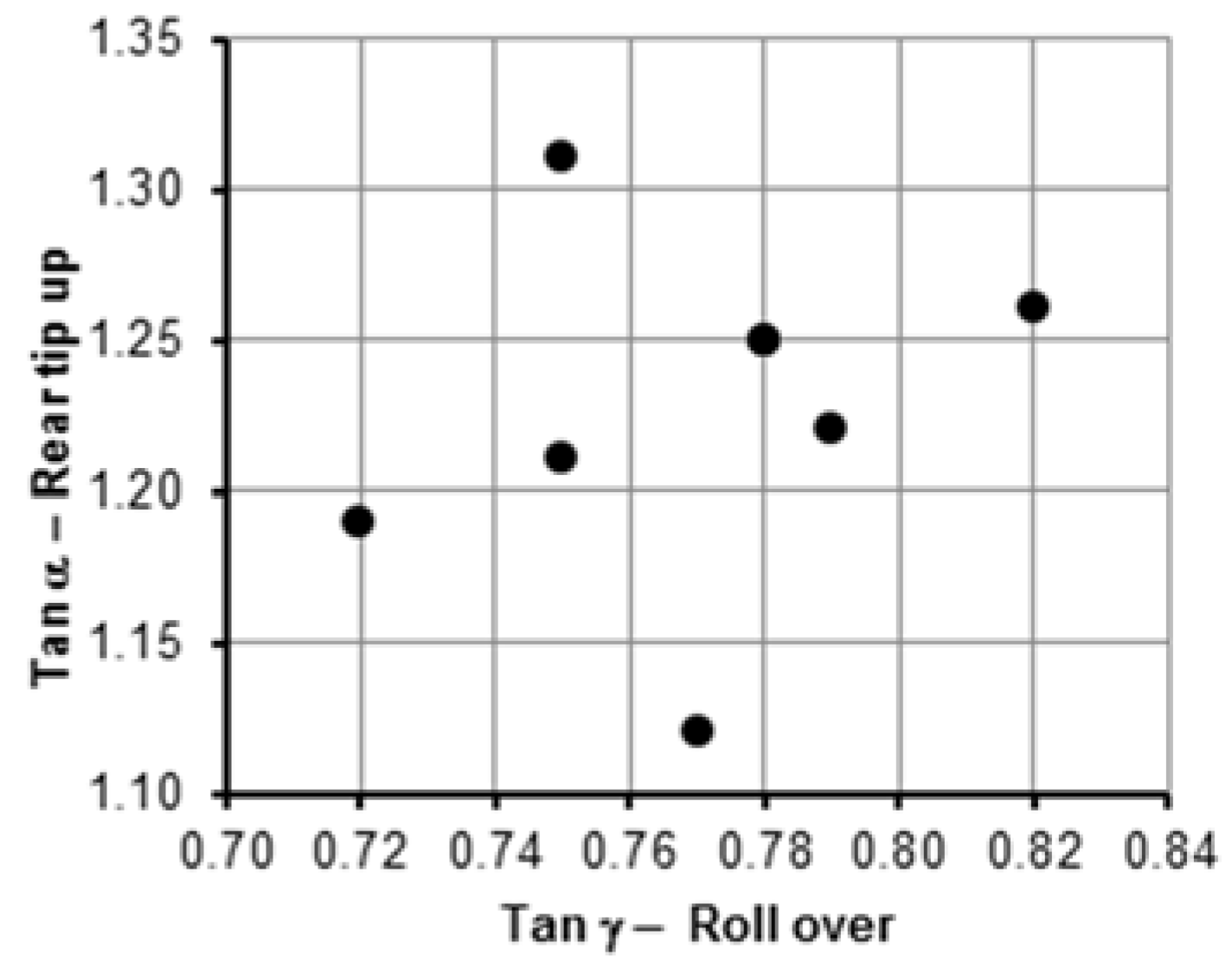
We can assume that the potential purchaser, seeking the most stable QB, would want at least moderate stability in both modes. To not suffer trauma in one mode is no consolation for a rider if they suffer trauma in the other.
Thus, if the static longitudinal and lateral instability angles are to be used as suitable parameters to represent the overall instability, we would want them to be at least moderately correlated. Figure 4 suggests that this does not appear to be so for the eight work QBs tested by the UNSW [2]; the values at (0.78:1.25) coincide. This data suggests that there is no established trend among manufacturers in designing QBs that are more stable in both directions; nor does it offer much hope for the evolution of static stability parameters greater than approximately 1.3 for tip-up and 0.82 for roll-over.
7. Conclusions
The instability of QBs and the associated trauma raises a complex set of mechanical, human and environmental problems. One approach to the solution is to seek to identify the technical characteristics that define the instability processes, not only in an idealized, static way, but also in the context of their dynamics and the variable environments in which they occur.
Previous work at UNSW associated with the measurement of the angles of static instability for the eight work QBs (effectively defined by their dimensional parameters) was designed to allow their ranking, and so provide information by which prospective purchasers could choose between more stable and less stable machines [2]. It was implied that this will place commercial pressure on the manufacturers of the latter to improve their stability. However, the results suggest that this will be of limited value because the differences between the machines were small—±10% for both rear tip-up and for roll-over modes of instability.
For the QB to become unstable, the shear strength of the soil/wheel patch must exceed the shear force due to the wheels. However, it appears that for many soils this will not be the case, and hence the QB will never reach the slope for static instability; the wheels will slip or slide off. This of course may bring its own issues of control and a resultant dynamic instability.
However, the operational stability of QBs (on which the rider ultimately relies) is a function, not only of the static effects discussed above, but also of the quasi-static effects such as the rolling resistance and centrifugal ‘force’, which in turn are based effectively on the mass of the QB. In operation, these will contribute to the overturning moment on the chassis, and hence any differences in mass will further blur attempts to distinguish between safer and less safe vehicles.
In addition to static instability parameters, there may be an additional dynamic component that arises from the inertial properties of the chassis and the wheels. Most QB operational instability will occur under these dynamic conditions and hence any realistic and practical discrimination between safer and less safe vehicles would need to consider both contributions to the instability.
In general terms, given the complex and daily changing, rural environment in which many QBs operate, it is unlikely that all the inherent dangerous features can be eliminated by design, all the operational errors can be avoided by education, and all the mis-perceptions by the rider can be correctly perceived.
J. Lock, the Queensland Coroner, cites others who correctly state: “… that people will make mistakes and that crashes will occur, but the punishment for making a mistake should not be death or serious injury. The focus should be on safer people (through training and education), but also on safer vehicles (that are forgiving of minor lapses in attention, minor errors of judgment, and that mitigate against injury risk if a crash occurs)” [5].
It is suggested that the best basis for such forgiveness is not to wait in expectation of some incremental changes in the static stability based on changes in basic chassis design. Rather, given the fact that occurrences of operational instability are statistically inevitable and analytically unpredictable (although many are probably avoidable), further research to reduce dynamic effects by improving suspension, steering and other features of the rolling chassis should be continued. It is also suggested that, following the road vehicle and tractor industries, further research on the inclusion of energy absorbing features in ROPS design should be undertaken. These suggestions could all be expected to help protect the rider in the complex circumstances that can be foreseen and also in those that cannot.
Acknowledgments
No funding for this work or its reporting was received.
Conflicts of Interest
The authors declare no conflict of interest.
Appendix A. Longitudinal Operational Instability
This analysis of a QB, in a condition of impending, rearward, operational instability shown in Figure A1, is presented as an extension of the simple, steady-state analysis given by Macmillan [4].
It should be noted that a rear wheel drive vehicle will not tip as a rigid body, rather the chassis will tip by rotating about the rear axle as the result of the moment (Mc) that acts on it as a reaction to the moment on the wheels (Mw). It is this former moment, and this moment alone, which tips the chassis of the QB over rearwards.
The moment arises from the static and quasi-static forces resisting motion of the QB up the slope, viz:
- static: the component of the weight down the slope;
- quasi-static: the rolling resistance of the wheels and any drawbar pull.
One significant limit on these forces, and hence on the moment that will tip the QB up, is the tractive capacity of the soil/wheel interface to generate a reaction (H) on the driving wheels to drive the QB forward. The simple non-dimensional measure of this capacity is the ‘traction coefficient’, which is defined as the ratio of the tangential (shearing) force to the radial (normal) force at the soil/wheel interface. It is usually given the symbol tan θ. (The only addition would be any impact on the front wheels that acted perpendicular to the slope and did not have any influence on the value of H).
For the purposes of this paper, instability is assumed to have occurred when the front wheels leave the ground.
Figure A1.
Vehicle being driven at a uniform speed up a slope, angle α.
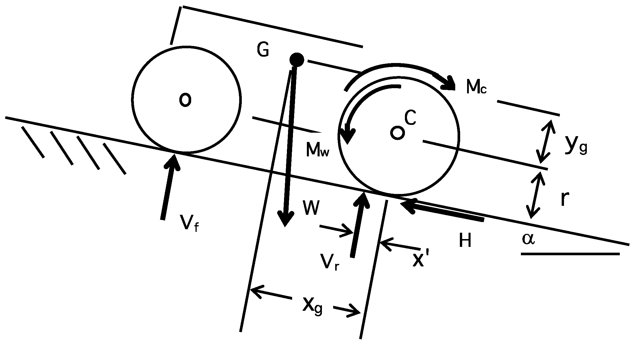
If at an angle α’ the front wheels just leave the ground, representing impending instability:
resolving perpendicular to the slope:
resolving along the slope:
taking moments about C for the wheels:
taking moments about C for the chassis:
but:
substituting:
thus, the coefficient of traction for static and quasi-static conditions will be:
if the rolling resistance of the wheels is neglected, x’ will be zero and the coefficient of traction for static conditions will be:
Vf = 0
Vr = W cos α’
H = W sin α’
Mw = H . r + Vr . x’
Mc + W sin α’. yg = W cos α’. xg
Mw = Mc
W sin α’. r + W cos α’ . x’ + W sin α’. yg = W cos α’. xg
Appendix B. Lateral Instability
In driving across a slope, the forces will be as shown in Figure A2.
Figure A2.
Vehicle being driven across a slope, angle γ.
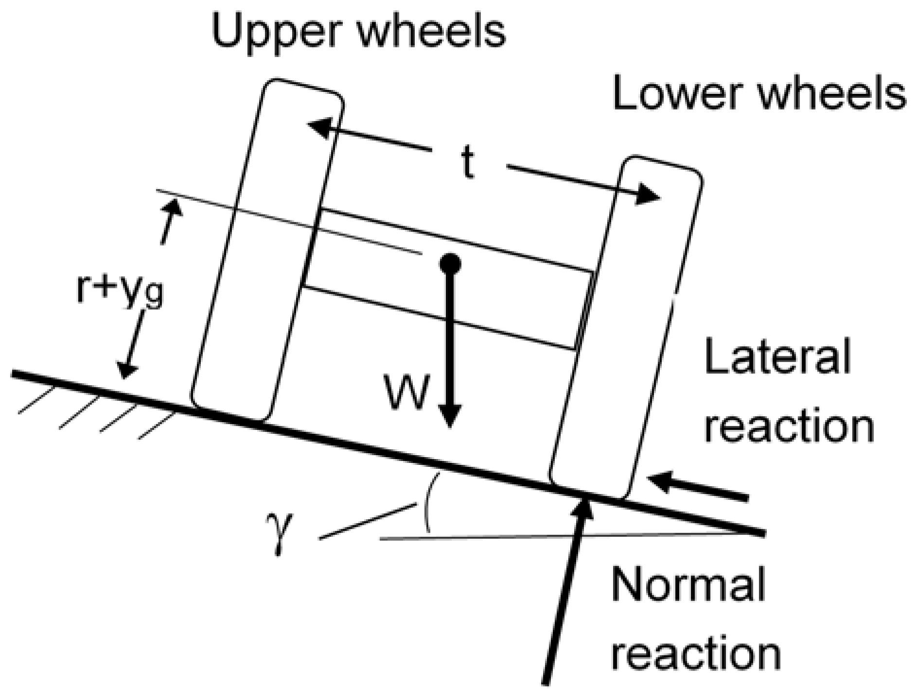
If impending instability is represented by the upper wheels just leaving the ground, the angle of impending instability tan γ, by rolling over, can be obtained by taking moments about the lower wheel ground contact point.
Appendix C

Table A1.
Dimensional data for work Quad-Bikes—Adapted from Grzebieta et al. [2].
Table A1.
Dimensional data for work Quad-Bikes—Adapted from Grzebieta et al. [2].
| Make | Honda | Honda | Yamaha | Polaris | Suzuki | Kawasaki | Kymco | CF Moto |
|---|---|---|---|---|---|---|---|---|
| Model | Fourtrax TRX 250 | Foreman TRX 500 FM | Grizzly YFM450FAP | Sportsman 450HO | Kingquad 400ASI | KVF 300 | MXU300 | CF 500 |
| Vehicle type | ATV—agric. | ATV—agric. | ATV—agric. | ATV—agric. | ATV—agric. | ATV—agric. | ATV—agric. | ATV—agric. |
| Driven wheels | Rear | 4WD | 4WD | 4WD | Rear | Rear | Rear | 4WD |
| Front track width | 795 | 930 | 860 | 1002 | 880 | 850 | 810 | 960 |
| Rear track width | 775 | 925 | 860 | 954 | 900 | 830 | 780 | 860 |
| Wheelbase | 1131 | 1281 | 1233 | 1283 | 1270 | 1165 | 1160 | 1290 |
| Front cargo capacity, kg | 15 | 30 | 40 | 41 | 30 | 20 | 20 | 20 |
| Rear cargo capacity, kg | 30 | 60 | 80 | 82 | 60 | 30 | 30 | 40 |
| Max. vehicle payload, kg | 175 | 220 | 210 | 220 | 172 | 164 | 165 | 180 |
| Unladen kerb mass, kg | 199 | 293 | 289.5 | 327 | 275.5 | 246 | 229 | 371.5 |
| Distance unladen CoG behind front axle, mm | 568 | 608 | 571 | 657 | 615 | 554 | 570 | 606 |
| Distance unladen CoG ahead rear axle, mm | 563 | 673 | 662 | 626 | 655 | 611 | 590 | 684 |
| CoG height, mm | 436 | 528 | 496 | 533 | 510 | 494 | 492 | 554 |
References
- Lower, T.; Pollock, K.; Herde, L. Australian quad bike fatalities: What is the economic cost? Aust. N. Z. J. Pub. Health 2014, 37, 173–178. [Google Scholar] [CrossRef] [PubMed]
- Grzebieta, R.; Rechnitzer, G.; Simmons, K.; McIntosh, A. Final Project Summary Report: Quad Bike Performance Project Test Results, Conclusions, and Recommendations. Available online: http://www.tars.unsw.edu.au/research/Current/Quad-Bike_Safety/Reports/Final_Summary_Report4-QBPP_Test_Results_Concl_Recom_Jan-2015.pdf (accessed on 18 October 2016).
- Payne, P.C.J.; Fountaine, E.R. The Shear Strength of Top Soils; Tech. Memo. No 42; National Institute of Agricultural Engineering (Silsoe Research Institute): Bedford, UK, 1951. [Google Scholar]
- Macmillan, R.H. The Mechanics of Tractor—Implement Performance; Theory and Worked Examples: A Text Book for Students and Engineers. Available online: https://minerva-access.unimelb.edu.au/handle/11343/33718/ (accessed on 18 October 2016).
- Lock, J. Inquest into Nine (9) Deaths Caused by Quad Bike Accidents. Deputy State Coroner. Office of the State Coroner Findings of Inquest; Brisbane, Queensland, Australia. Available online: http://www.courts.qld.gov.au/__data/assets/pdf_file/0018/432306/cif-quadbikeaccidents-20150803.pdf (accessed on 18 October 2016).
Figure 1.
Static rear longitudinal instability angles (shown as tan α) for the eight work Quad Bikes (QBs) and a range of typical traction coefficients (tan θ) for tyres on agricultural soils.
Figure 1.
Static rear longitudinal instability angles (shown as tan α) for the eight work Quad Bikes (QBs) and a range of typical traction coefficients (tan θ) for tyres on agricultural soils.
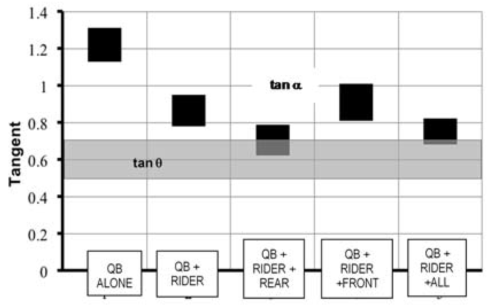
Figure 2.
Plot of the slope as tan α verses stand-alone mass for work QBs in rear longitudinal instability.
Figure 2.
Plot of the slope as tan α verses stand-alone mass for work QBs in rear longitudinal instability.
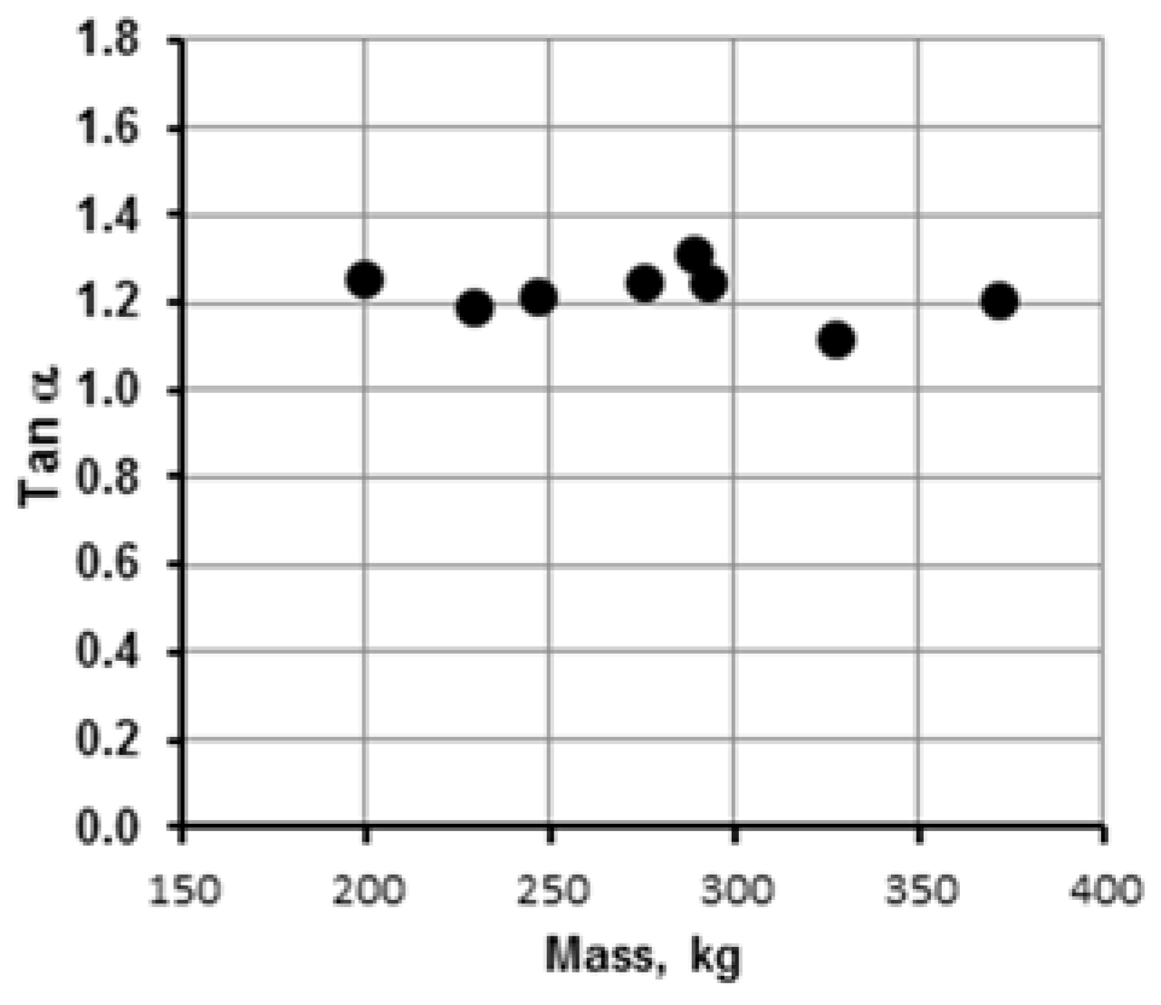
Figure 3.
Static lateral instability angles (shown as tan γ) for the eight work QBs, and a range of typical lateral traction coefficients (tan θ, assumed equal to the longitudinal values shown in Figure 1) for tyres on agricultural soils.
Figure 3.
Static lateral instability angles (shown as tan γ) for the eight work QBs, and a range of typical lateral traction coefficients (tan θ, assumed equal to the longitudinal values shown in Figure 1) for tyres on agricultural soils.
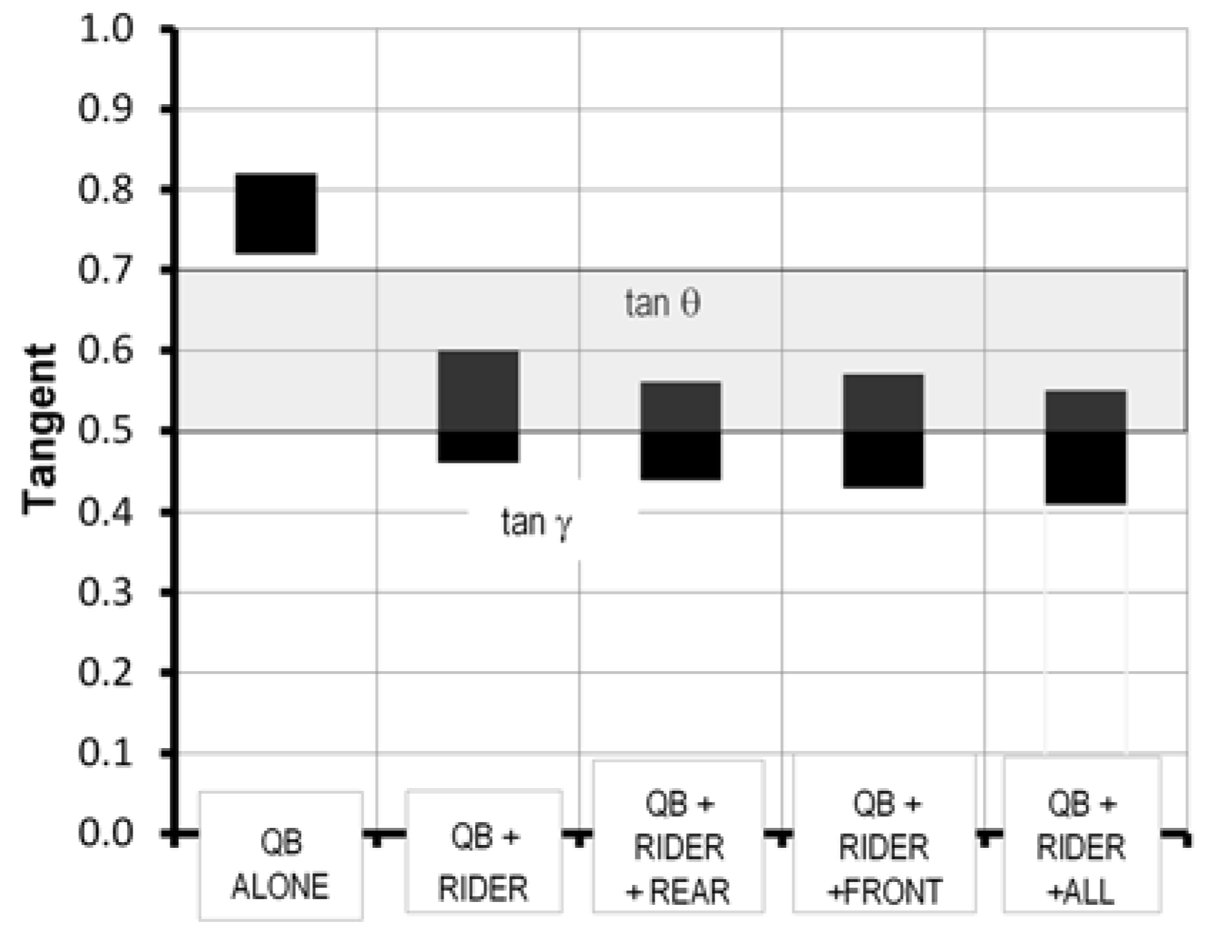
Figure 4.
Static instability for rear longitudinal versus lateral directions for eight work QBs; two sets of data values at (0.78:1.25) coincide.
Figure 4.
Static instability for rear longitudinal versus lateral directions for eight work QBs; two sets of data values at (0.78:1.25) coincide.

© 2017 by the author. Licensee MDPI, Basel, Switzerland. This article is an open access article distributed under the terms and conditions of the Creative Commons Attribution (CC BY) license (http://creativecommons.org/licenses/by/4.0/).
Share and Cite
MDPI and ACS Style
Macmillan, R.H. Quad-Bike Operational Instability. Safety 2017, 3, 15. https://doi.org/10.3390/safety3020015
AMA Style
Macmillan RH. Quad-Bike Operational Instability. Safety. 2017; 3(2):15. https://doi.org/10.3390/safety3020015
Chicago/Turabian StyleMacmillan, Ross H. 2017. "Quad-Bike Operational Instability" Safety 3, no. 2: 15. https://doi.org/10.3390/safety3020015
Note that from the first issue of 2016, this journal uses article numbers instead of page numbers. See further details here.