Article

A ZnO Nanoparticle-Coated Long Period Fiber Grating as a Carbon Dioxide Gas Sensor

Department of Mechanical Engineering, National Kaohsiung University of Applied Sciences, Kaohsiung 807, Taiwan
*
Author to whom correspondence should be addressed.
Inventions 2016, 1(4), 21; https://doi.org/10.3390/inventions1040021
Submission received: 20 July 2016 / Revised: 22 September 2016 / Accepted: 17 October 2016 / Published: 26 October 2016

Abstract

:
This study proposes a long period fiber grating (LPFG) with a zinc oxide (ZnO) nanoparticle layer for use as a carbon dioxide (CO2) gas sensor. Inductively coupled plasma (ICP) etching, corona treatment, and electrostatic spraying were used to fabricate this ZnO nanoparticle-coated LPFG CO2 gas sensor. Repeated gas sensor tests showed that, when a 15% CO2 mixture was injected (0.2 L/min) into a closed chamber into which the sensor had been placed, the CO2 gas was absorbed by the ZnO nanoparticle-coated LPFG sensor. In these tests, the transmission loss gradually decreased, and the maximum transmission loss was 2.039 dB. The concentration test results showed that as the concentration of CO2 introduced into the chamber was increased, the rate of the transmission loss change was increased in direct proportion. In addition, the sensitivity was 0.0513 dB/%. The results confirm that this low-cost ZnO nanoparticle-coated LPFG gas sensor was successfully applied to the measurement of CO2 gas. Therefore, the proposed ZnO nanoparticle-coated LPFG can be used to measure CO2 gas.

Graphical Abstract

1. Introduction

Emissions from factories and vehicles are primarily composed of carbon dioxide (CO2) gas, which is one of the major greenhouse gases contributing to global warming. As such, gas sensing elements that can be used to test for industrial gases must be developed for the application in harsh environments, and these sensors must be specifically designed to test for a single gas. Semiconductors that have been gradually developed in recent years for gas sensing applications have the advantage of being compact, yet these semiconductors are unsuitable for use in environments with electromagnetic interference, high temperatures, or high humidity.
Long period fiber grating (LPFG) sensors are extremely sensitive to the refractive index [1,2], strain [3,4], and temperature [5,6] changes and are not affected by electromagnetic waves. In recent years, they have been widely applied in the engineering, biomedicine, and food industries. This study used a zinc oxide (ZnO) nanoparticle-coated [7,8,9,10] LPFG sensor as a CO2 gas sensing element. More specifically, the ZnO nanoparticles absorbed the CO2 gas, changing the refractive index of the LPFG [11], thus changing the transmission loss of the LPFG sensor and effectively enabling it to sense the CO2. In 2003, Segawa et al. [12] proposed a CO2 gas sensor that was manufactured by applying a thymol blue indicator to an optic fiber using the sol-gel method. When thymol blue absorbs CO2, it creates carbonic acid, which is slightly acidic; thus, the thymol blue turns yellow, indicating the presence of CO2. When the sensor detects CO2, the transmission loss changes; when nitrogen gas is introduced, the loss reverts to normal. In the aforementioned study, when the CO2 concentration was increased from 0% to 100%, the loss increased from 0 to 2.5 dB. In 2007, Samarasekaea et al. [13] sputter-coated a layer of ZnO onto silicon plates to detect CO2 gas. The silicon plates were placed under 8.5 mbar of pressure at 130 or 153 °C and processed for 18 h. The ZnO grains sputter-coated at 130 °C were 20.66 nm in size; those sputter-coated at 153 °C were 24.8 nm in size. These results showed that the grain size increased along with the sputtering temperature. As the smaller grains had a larger surface-area-to-volume ratio that allowed them to absorb more CO2, the resulting transmission loss changes were also increased. Therefore, a ZnO membrane was sputter-coated at 130 °C to detect CO2. The results indicated that, with minimal changes in nitrogen gas, the sensitivity to CO2 was greatest at 100 °C.
In 2008, Chu et al. [14] used the sol–gel method to mix alkyl and perfluoroalkyl doped with pH sensitive fluorescent dye to detect CO2 gas. CO2 gas was detectable in concentrations from 0% to 100%. The sensor intensity gradually decreased, so nitrogen gas and CO2 carrier gases were used. The response time of the sensor was 1.7 s when switching from nitrogen gas to CO2 gas and 38.5 s when switching from CO2 to nitrogen. This shows that by switching between nitrogen gas and CO2, the sensor could stably detect CO2 gas. In 2009, Chu et al. [15] used the sol–gel method to mix hydroxy-3,6,8-pyrenetrisulfonic acid trisodium salt (HPTS) and tetraethylorthosilane (TEOS) to detect CO2, doping HPTS with silicon dioxide to increase sensor sensitivity and stability. When the 100% CO2 environment was switched to nitrogen gas, the response time was 195.4 s. CO2 gas was introduced in concentrations from 0% to 100%, and ( I 0 I ) / I increased along with the gas concentration with a linearity of 0.9974. In 2012, Konstantaki et al. [16] used zinc oxide (ZnO) nanorods overlaid on LPFG for ethanol vapor sensing. They used ZnO nanorod layers of different thicknesses to measurement the ethanol. The preliminary results demonstrated the ZnO overlaid LPFG probe could effectively measure the ethanol vapor. The literature above shows that, in terms of sensor-coating methods, past studies have primarily used sputter-coating or the sol–gel method to coat a sensor layer onto sensors used to detect gases. Different gases can be absorbed depending on the layer coated onto the fiber optic sensors in order to change the refractive index, which in turn changes the spectral transmission loss and wavelength of the LPFG and allows for the detection of a specific gas. Therefore, this study used ZnO nanoparticle-coated LPFG to detect CO2 gas in a room temperature environment.

2. Working Principle of the CO2 Gas Sensor

The ZnO nanoparticle-coated LPFG has periodic surface-corrugated gratings. As an external load is applied to it, the strain field in the longitudinal direction of the LPFG is modulated as a square wave because of the periodic surface grating structure of the optical fiber. Based on the elastic-optic effect [11], the refractive index of the LPFG will also be modulated as a periodic square wave distribution along the optical fiber.
When light is transmitted through the LPFG, the periodic refractive index grating structure generates a resonant attenuation dip in the spectrum based on the coupled mode theory [17]. The transmission loss of light transmitted through LPFG is defined [17] as
T = 1 1 + κ d c κ c o c l a c cos 2 ( ( κ c o c l a c ) 2 + ( κ d c ) 2 L )
where κ d c , κ c o c o d c , and κ c l c l d c are all LPFG coupling coefficients, κ c o c l a c is an AC coupling coefficient, and κ d c = κ c o c o d c = κ c l c l d c = 0. Thus, Equation (1) can be simplified to
T = cos 2 ( κ c o c l a c L )
The transmission loss of light transmitted through LPFG is a cosine squared function, where the transmission loss is dependent on the coupling coefficients and the length of the grating. The combination of CO2 gas and the ZnO nanoparticle sensing layer changes the effective refractive index for the cladding in Equation (2), thus affecting the coupling coefficient ( κ c o c l a c ) such that, when the gas is detected, the coupling coefficients for the cladding and core become smaller, decreasing the transmission loss. Inputting the experimental data into Equation (2) yields the changes in loss.

3. Manufacturing Process and Experiment Setup

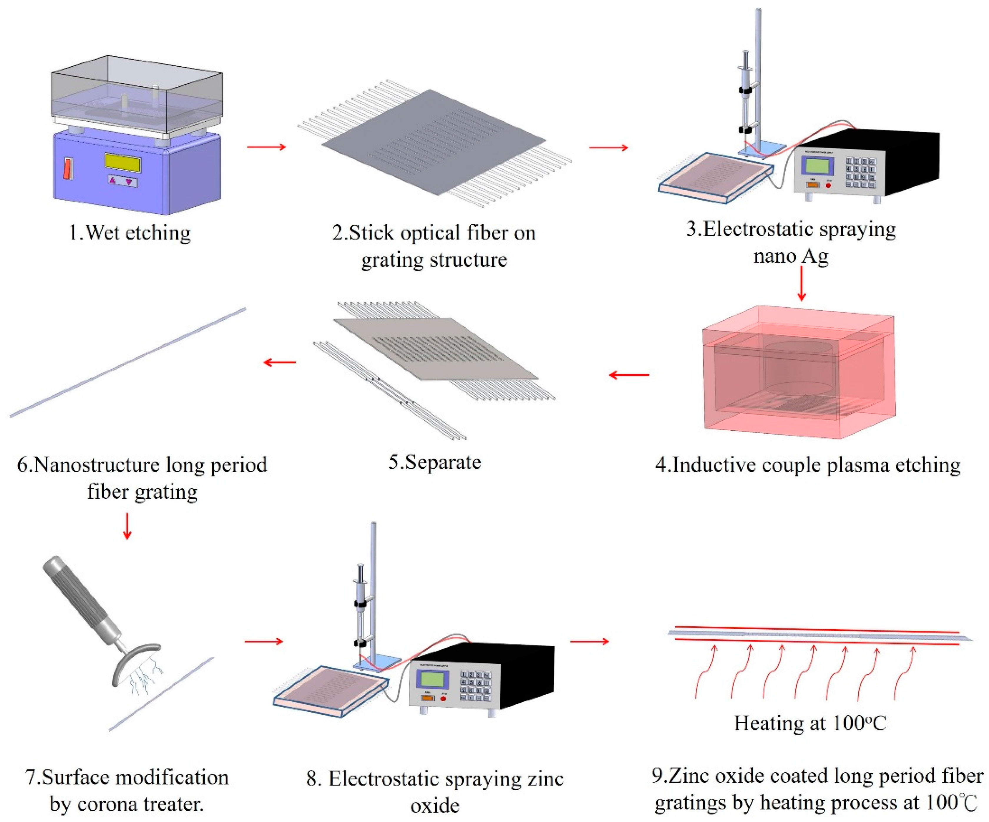
3.1. The ZnO-Coated LPFG Gas Sensor Manufacturing Process

The manufacturing process for the ZnO nanoparticle-coated LPFG CO2 sensor is shown in Figure 1. First, the single mode fiber (SMF) was subjected to buffered oxide etching (BOE) to reduce the diameter from 125 to 40 μm. Next, the optical fiber was adhered to a steel grating structure that then underwent electrostatic spraying with silver nanoparticles. Next, inductively coupled plasma (ICP) etching was used to create the LPFG structure. The LPFG etching depth was 11.5 μm, as shown in the Figure 2a inset. This LPFG sensor then underwent surface modification using a corona treater to change the surface from hydrophobic to hydrophilic so that the ZnO nanoparticles would stick to the fibers more easily. ZnO nanoparticles were then electrostatically sprayed onto the fibers, completely covering them. Finally, the ZnO-covered LPFG was heated at 100 °C to release CO2 and increase the stability of the sensor layer. The proposed LPFG was fabricated by the MEMS production method, which allows for mass production such that the cost of producing high numbers of the sensor can be kept relatively low. An SEM image of the ZnO nanoparticle-coated LPFG sensor is shown in Figure 2b.

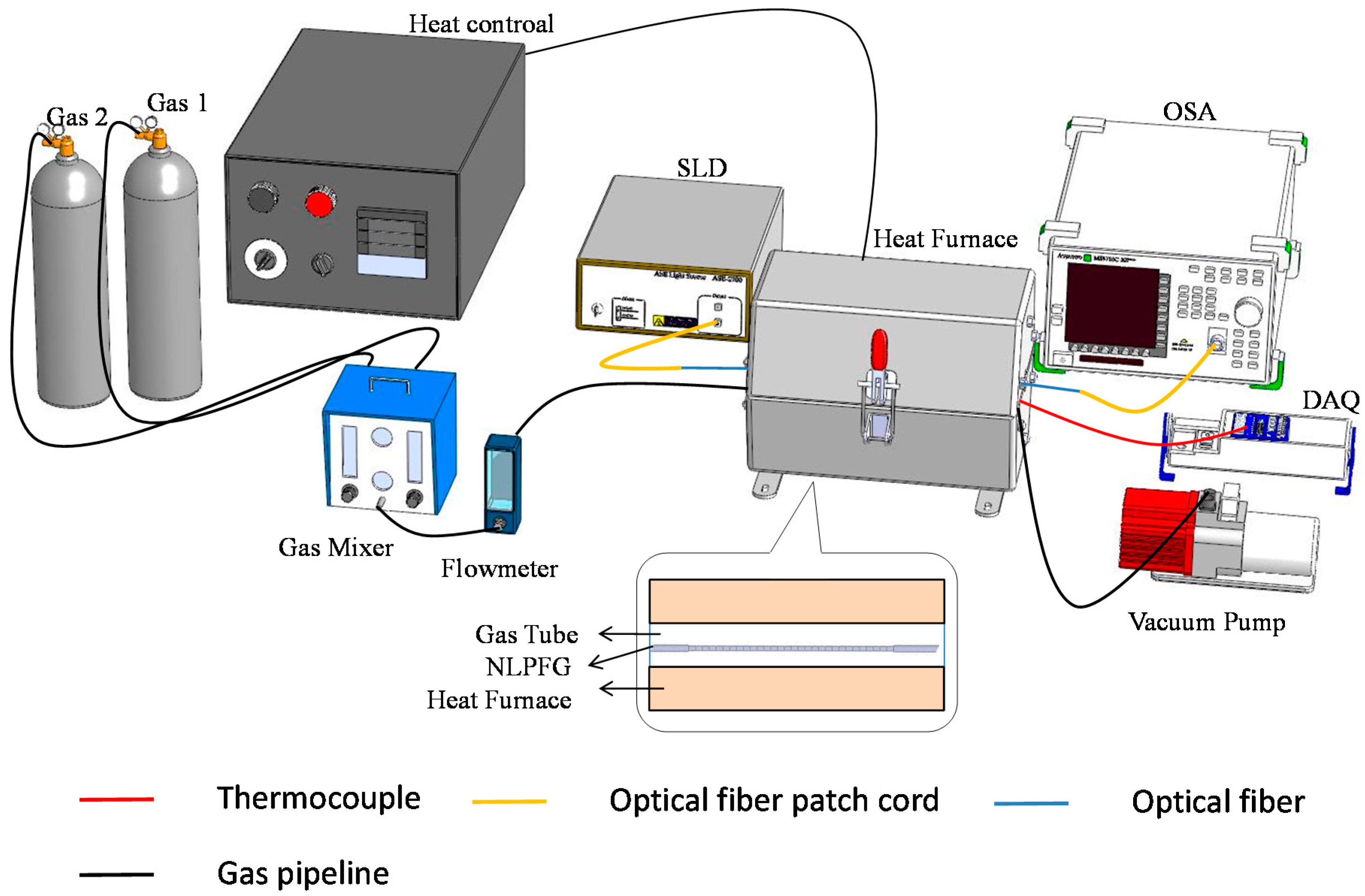
3.2. CO2 Gas Sensor Experiment Setup

Figure 3 shows the CO2 gas sensor experimental setup. The ZnO nanoparticle-coated LPFG sensor was sealed inside of a U-shaped quartz tube, which was placed inside of a gas sensor chamber fitted with a gas loading and unloading system. A gas mixer adjusted the concentration of the CO2 gas for the experiments using different concentrations of CO2. A spectrometer was used to observe the changes in the LPFG sensor spectrum after different concentrations of CO2 were introduced for analysis.

4. Results and Discussion

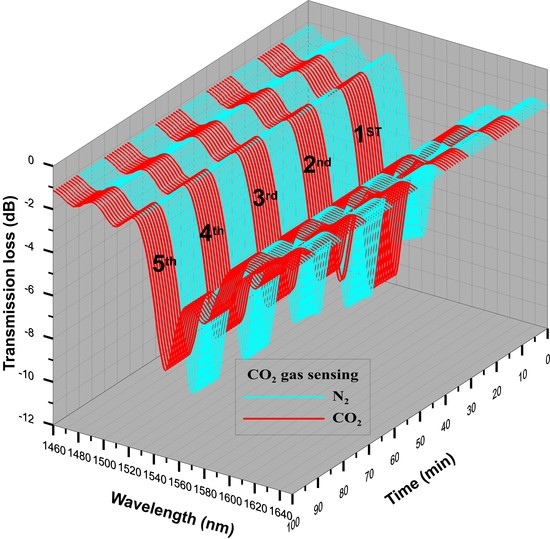
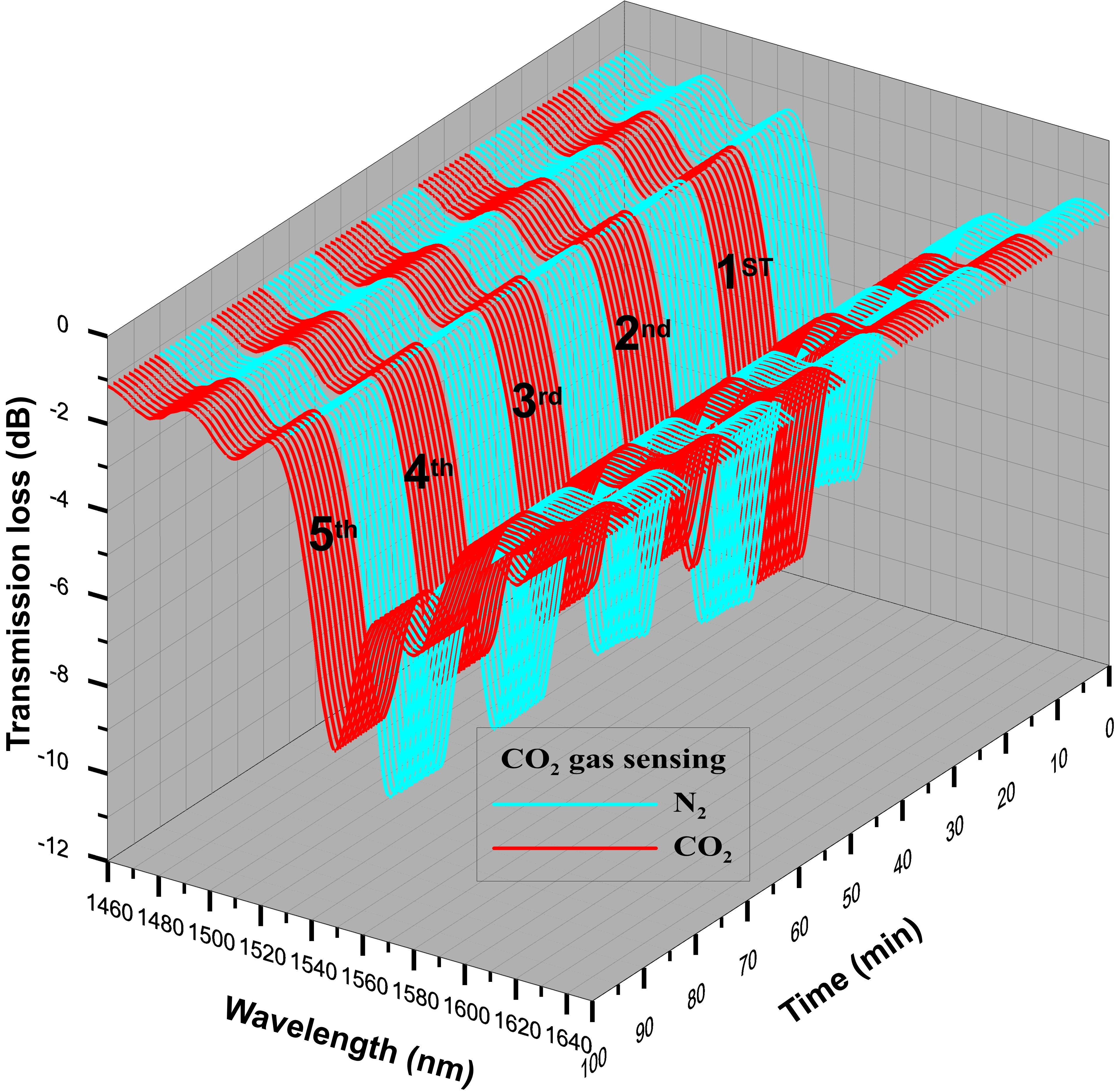
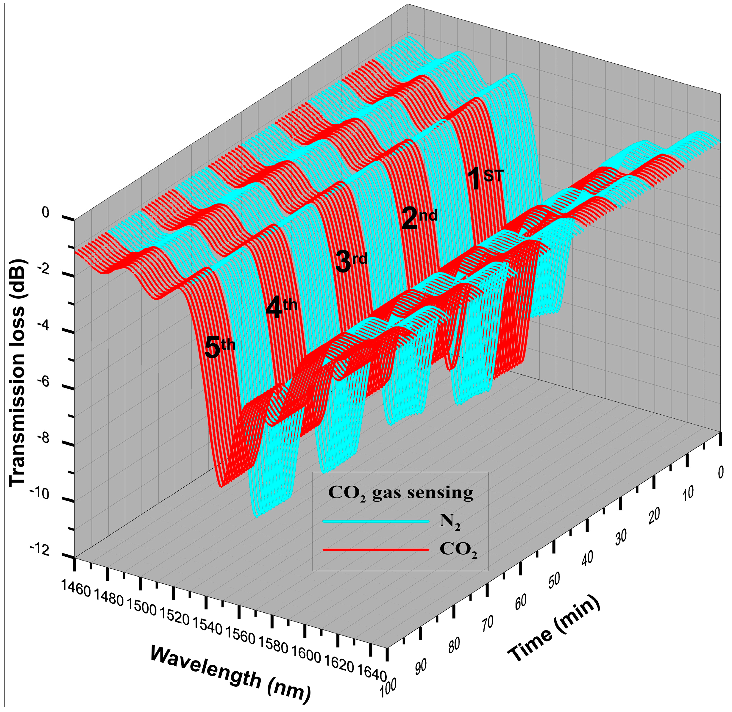
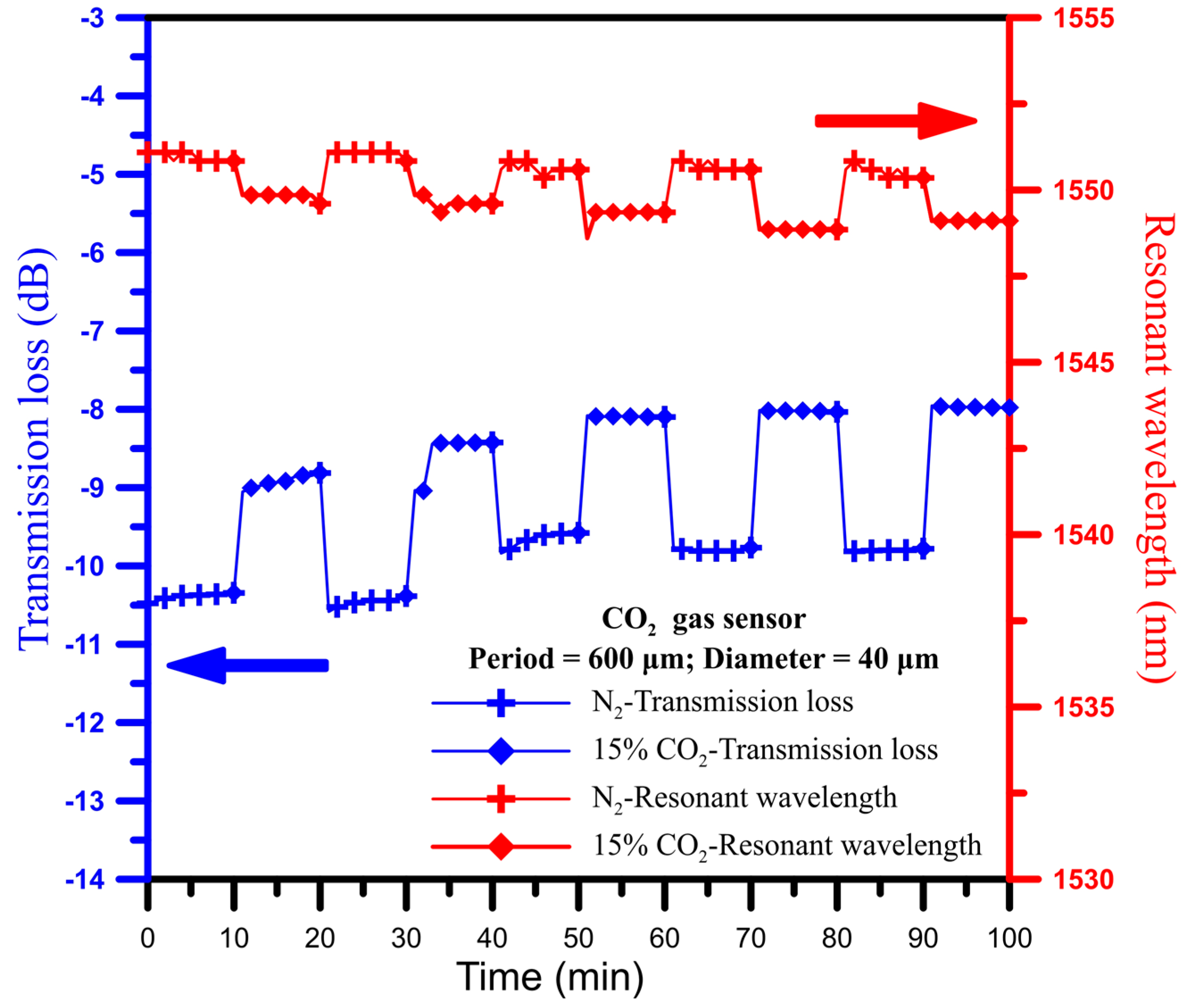
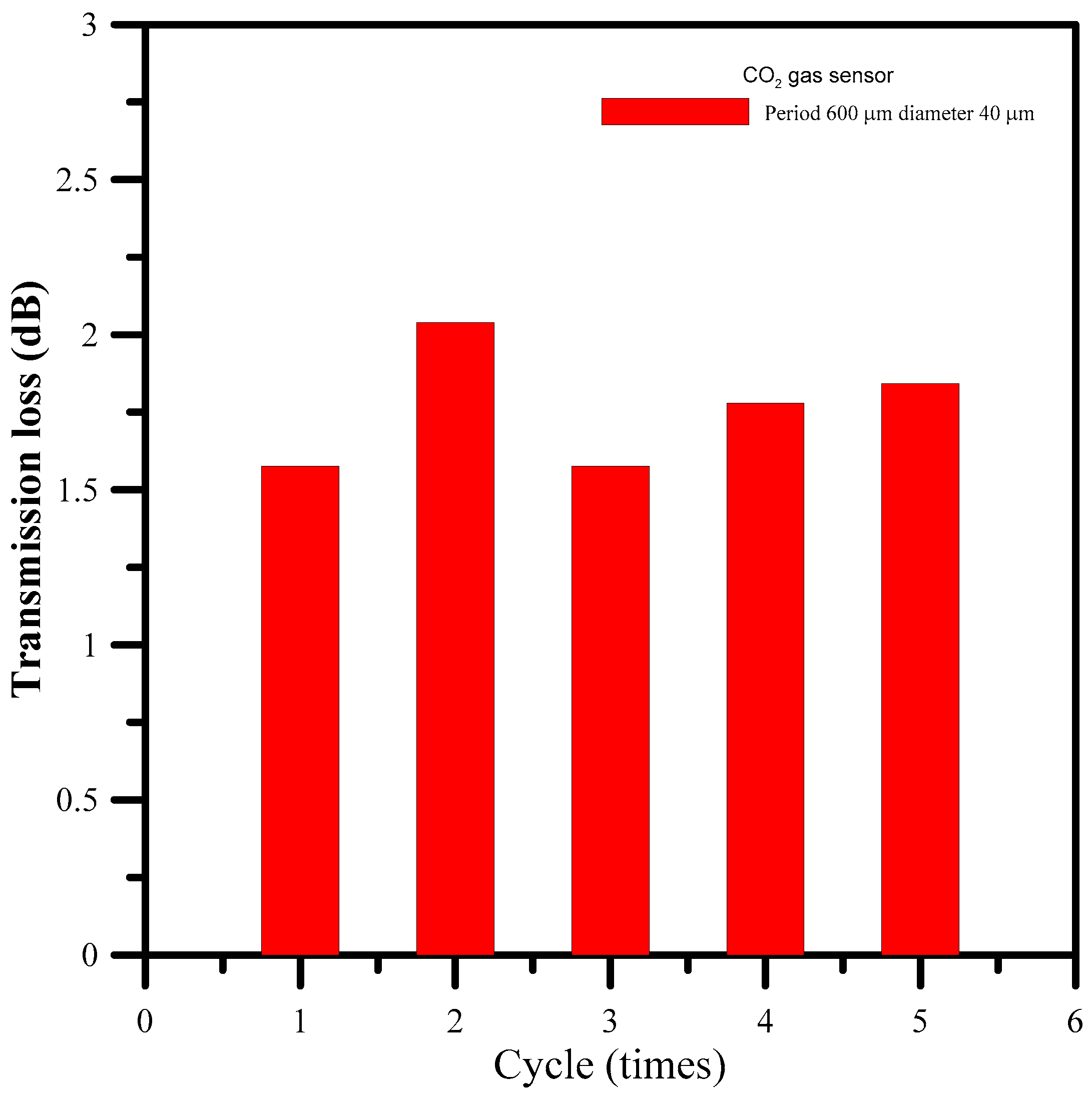
4.1. CO2 Gas Sensing Experiment Results

An LPFG sensor with a diameter of 40 μm and a period of 600 μm was used in this experiment. Electrostatic spraying technology was also used to apply the ZnO nanoparticle layer to detect CO2. Figure 4 shows the spectra of the sensor in repeated CO2 gas sensing experiments. We tracked the spectrum dip to monitor the variation in gas concentration and utilized the spectrum data in creating Figure 5. Figure 5 shows the repeatability of the CO2 gas sensor spectral analysis. At an initial concentration of 15% CO2, the corresponding transmission loss gradually lessened and the wavelength exhibited a slight blue shift. In the first and second cycles, the variation in transmission loss was due to the sensing layer instability. Figure 6 shows the changes in transmission loss for the CO2 sensor. The figure shows that, among the five cycles of the experiment, the second had the largest transmission loss (2.038 dB); the mean transmission loss was 1.762 dB, and the standard deviation was 0.195 dB. The response time of the CO2 gas sensor was about 6 min.

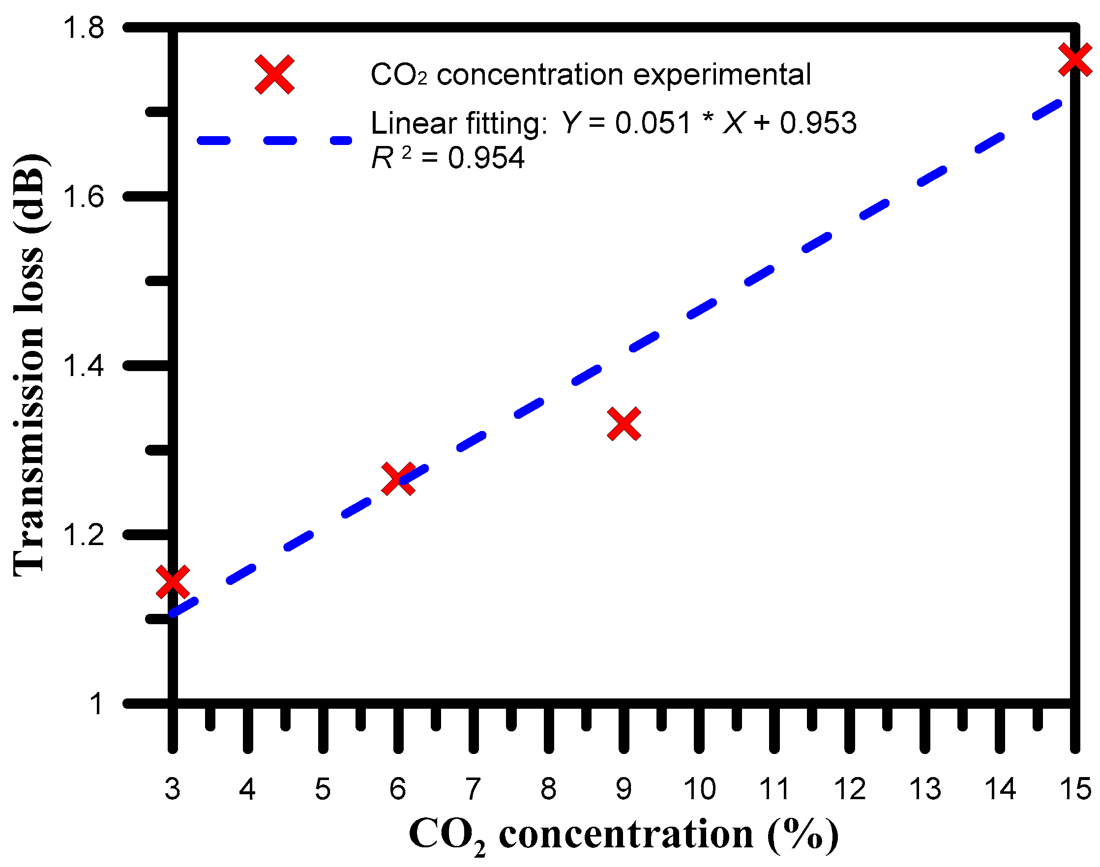
4.2. CO2 Gas Concentration Sensing Experiment

After the 600 μm period optic fiber 40 μm in diameter was completely sealed and coated in ZnO, CO2 at concentrations of 3%, 6%, 9%, and 15% were introduced for 20 min to measure the spectral changes and calculate the transmission loss variation (Figure 7). Figure 7 shows that after introducing different concentrations of CO2 gas, the transmission loss gradually decreased. The changes in loss for CO2 concentrations of 3%, 6%, 9%, and 15% were 1.144, 1.266, 1.331, and 1.762 dB, respectively. As the CO2 concentration increased, the transmission loss increased; the sensitivity was 0.051 dB/%, and the linearity was 0.954.

5. Conclusions

This study used a LPFG sensor with a diameter of 40 μm and a period of 600 μm coated with ZnO nanoparticles to detect CO2 gas. The results from replicated experiments showed that, after adding 15% CO2 gas, the transmission loss gradually decreased. The results from five cyclic experiments showed that the mean change in loss was 1.762 dB, with a standard deviation of 0.195 dB. The concentration experiment results showed that, as the CO2 concentration increased, the transmission loss increased. The sensitivity of this CO2 sensor was 0.0513 dB/%, and the linearity was 0.954. Therefore, this ZnO nanoparticle-coated LPFG sensor moderate repeatability and could successfully detect CO2 gas concentrations at room temperature.

Acknowledgments

This work was supported by the Ministry of Science and Technology, Taiwan (grant number MOST 103-2221-E-151-009-MY3 and 105-2623-E-151-002-D).

Author Contributions

Chia-Chin Chiang designed the study methods and experiments, analyzed the data, and wrote the paper; Chao-Wei Wu and Chien-Chung Wu conducted the experiments and analyzed the experimental data.

Conflicts of Interest

The authors declare no conflict of interest.

References

  1. Qi, L.; Zhao, C.L.; Yuan, J.; Ye, M.; Wang, J.; Zhang, Z.; Jin, S. Highly reflective long period fiber grating sensor and its application in refractive index sensing. Sens. Actuator B Chem. 2014, 193, 185–189. [Google Scholar] [CrossRef]
  2. Zou, F.; Liu, Y.; Deng, C.; Dong, Y.; Zhu, S.; Wang, T. Refractive index sensitivity of nano-film coated long-period fiber gratings. Opt. Express 2015, 23, 1114–1124. [Google Scholar] [CrossRef] [PubMed]
  3. Yoon, M.S.; Kim, H.J.; Kim, S.J.; Han, Y.G. Influence of the waist diameters on transmission characteristics and strain sensitivity of microtapered long-period fiber gratings. Opt. Lett. 2013, 38, 2669–2672. [Google Scholar] [CrossRef] [PubMed]
  4. Wang, P.; Xian, L.; Li, H. Fabrication of phase-shifted long-period fiber grating and its application to strain measurement. IEEE Photon. Technol. Lett. 2015, 27, 557–560. [Google Scholar] [CrossRef]
  5. Bai, Z.; Zhang, W.; Gao, S.; Zhang, H.; Wang, L.; Liu, F. Bend-insensitive long period fiber grating-based high temperature sensor. Opt. Fiber Technol. 2015, 21, 110–114. [Google Scholar] [CrossRef]
  6. Zou, F.; Liu, Y.; Zhu, S.; Deng, C.; Dong, Y.; Wang, T. Temperature Sensitivity Enhancement of the Nano-Film Coated Long-Period Fiber Gratings. IEEE Sens. J. 2016, 16, 2460–2465. [Google Scholar] [CrossRef]
  7. Renganathan, B.; Sastikumar, D.; Gobi, G.; Yogamalar, N.R.; Bose, A.C. Nanocrystalline ZnO coated fiber optic sensor for ammonia gas detection. Opt. Laser Technol. 2011, 43, 1398–1404. [Google Scholar] [CrossRef]
  8. Coelho, L.; Viegas, D.; Santos, J.L.; de Almeida, J.M.M.M. Characterization of zinc oxide coated optical fiber long period gratings with improved refractive index sensing properties. Sens. Actuator B Chem. 2016, 223, 45–51. [Google Scholar] [CrossRef]
  9. Dikovska, A.O.; Atanasov, P.A.; Andreev, A.T.; Zafirova, B.S.; Karakoleva, E.I.; Stoyanchov, T.R. ZnO thin film on side polished optical fiber for gas sensing applications. Appl. Surf. Sci. 2007, 254, 1087–1090. [Google Scholar] [CrossRef]
  10. Coelho, L.; Viegas, D.; Santos, J.L.; de Almeida, J.M.M.M. Zinc oxide coated optical fiber long period gratings for sensing of volatile organic compounds. In Proceedings of the SPIE Photonics Europe, International Society for Optics and Photonics, Brussels, Belgium, 3–7 April 2016.
  11. Chang, S.P.; Wen, C.H.; Chang, S.J. Two-dimensional ZnO nanowalls for gas sensor and photoelectrochemical applications. Electron. Mater. Lett. 2014, 10, 693–697. [Google Scholar] [CrossRef]
  12. Segawa, H.; Ohnishi, E.; Arai, Y.; Yoshida, K. Sensitivity of fiber-optic carbon dioxide sensors utilizing indicator dye. Sens. Actuator B Chem. 2003, 94, 276–281. [Google Scholar] [CrossRef]
  13. Samarasekara, P.; Yapa, N.; Kumara, N.; Perera, M. CO2 gas sensitivity of sputtered zinc oxide thin films. Bull. Mater. Sci. 2007, 30, 113–116. [Google Scholar] [CrossRef]
  14. Chu, C.S.; Lo, Y.L. Fiber-optic carbon dioxide sensor based on fluorinated xerogels doped with HPTS. Sens. Actuator B Chem. 2008, 129, 120–125. [Google Scholar] [CrossRef]
  15. Chu, C.S.; Lo, Y.L. Highly sensitive and linear optical fiber carbon dioxide sensor based on sol-gel matrix doped with silica particles and HPTS. Sens. Actuator B Chem. 2009, 143, 205–210. [Google Scholar] [CrossRef]
  16. Konstantaki, M.; Klini, A.; Anglos, D.; Pissadakis, S. An ethanol vapor detection probe based on a ZnO nanorod coated optical fiber long period grating. Opt. Express 2012, 20, 8472–8484. [Google Scholar] [CrossRef] [PubMed]
  17. Lin, C.Y.; Wang, L.A.; Chern, G. Corrugated long-period fiber gratings as strain, torsion, and bending sensors. J. Lightw. Technol. 2001, 19, 1159–1168. [Google Scholar]
Figure 1. Zinc oxide (ZnO) nanoparticle-coated long period fiber grating (LPFG) carbon dioxide (CO2) gas sensor manufacturing process.
Inventions 01 00021 g001
Figure 2. (a) SEM image of the LPFG. Inset: The notch depth of the LPFG; (b) SEM image of the ZnO nanoparticle-coated LPFG CO2 gas sensor.
Inventions 01 00021 g002
Figure 3. Experimental setup for CO2 gas sensing.
Inventions 01 00021 g003
Figure 4. The spectra of the sensor in repeated (five cycle) CO2 gas sensing experiments.
Inventions 01 00021 g004
Figure 5. Repeatability of the CO2 gas sensor spectral analysis.
Inventions 01 00021 g005
Figure 6. Changes in transmission loss for the CO2 gas sensor.
Inventions 01 00021 g006
Figure 7. Correlation between CO2 concentration and transmission loss.
Inventions 01 00021 g007

