
Sensor Pods: Multi-Resolution Surveys from a Light Aircraft

 ,
,
Abstract
:1. Introduction
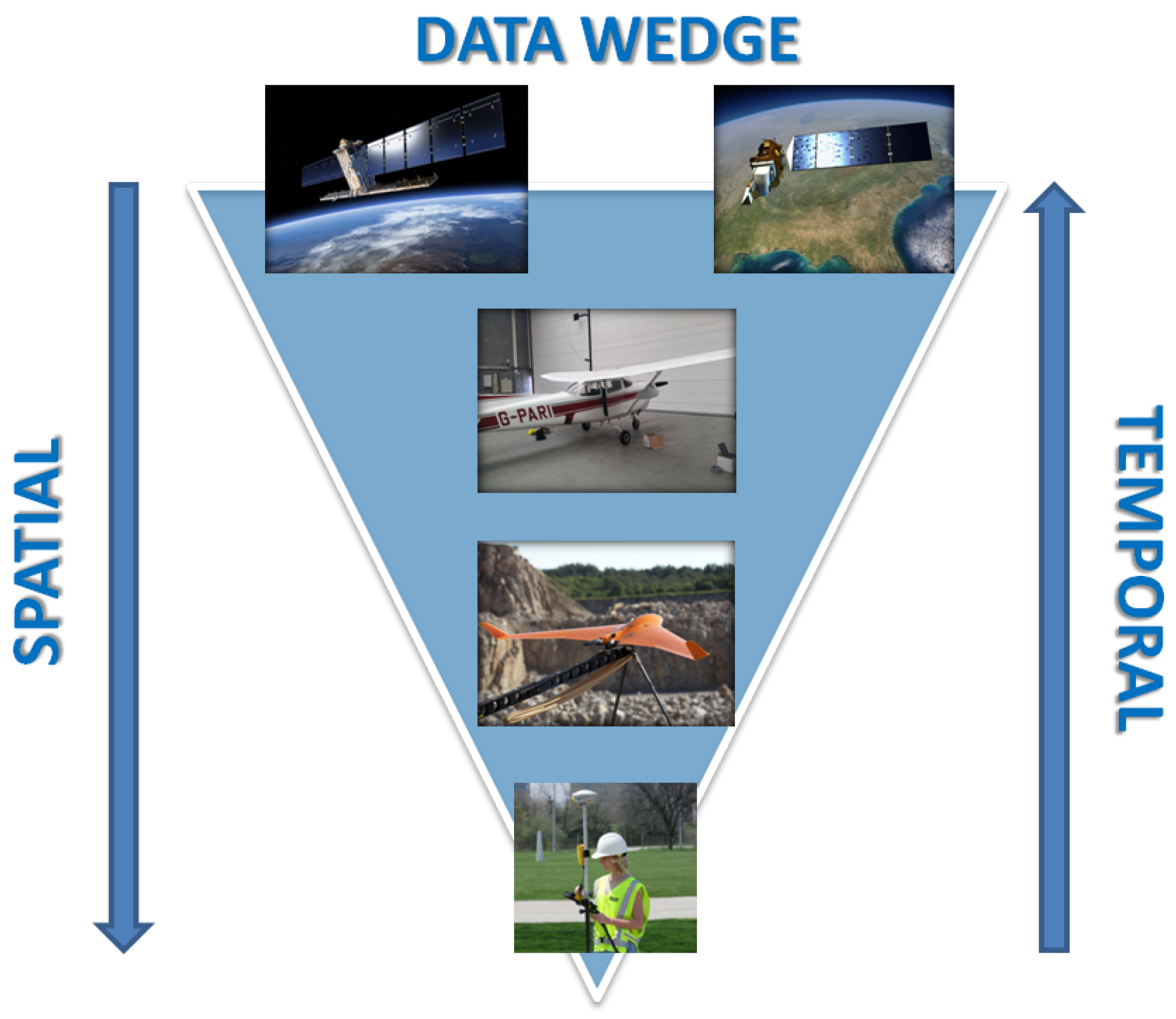
1.1. Satellite vs Airborne Platforms
1.2. Airborne vs Remotely Piloted Airborne Systems
1.3. Demonstrating the Potential of a Hybrid Approach
- Design an aerial sensor pod to re-purpose four RPAS-dedicated spectral sensors.
- Develop logging and navigation capability to synchronize and spatially locate four spectrally diverse streams of RPAS imagery.
- Fuse the resulting snapshot, video and pushbroom imagery for spectral and spatial analysis.
2. Platform Development
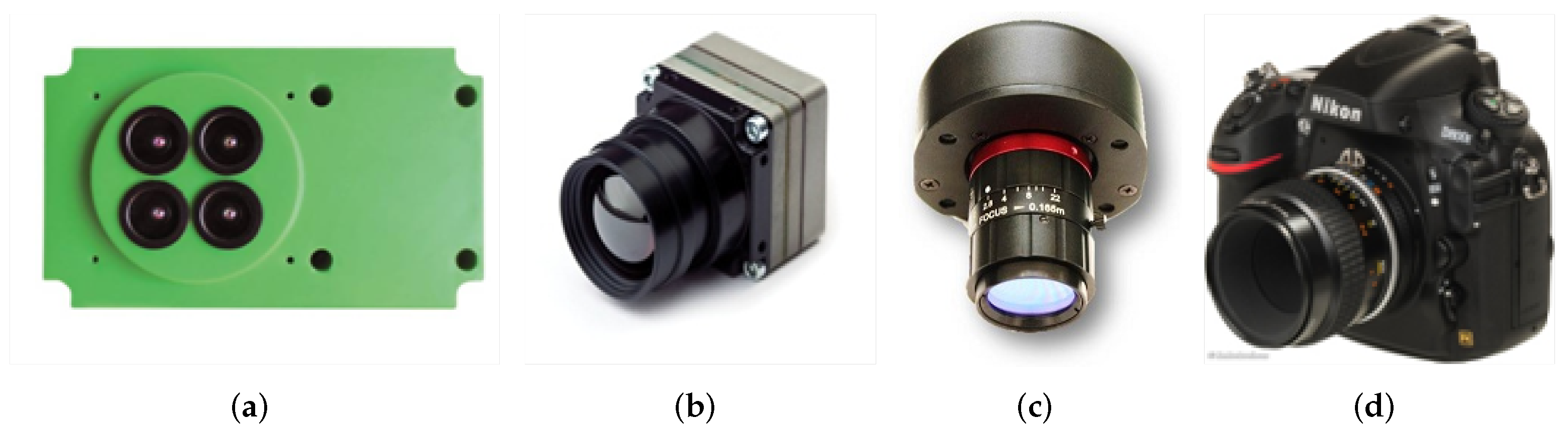
2.1. RPAS Sensors
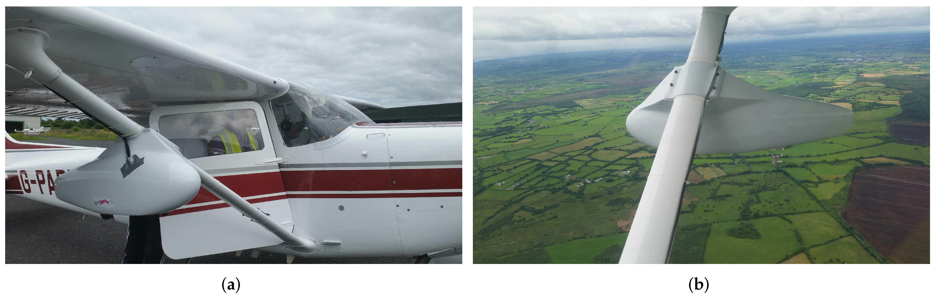
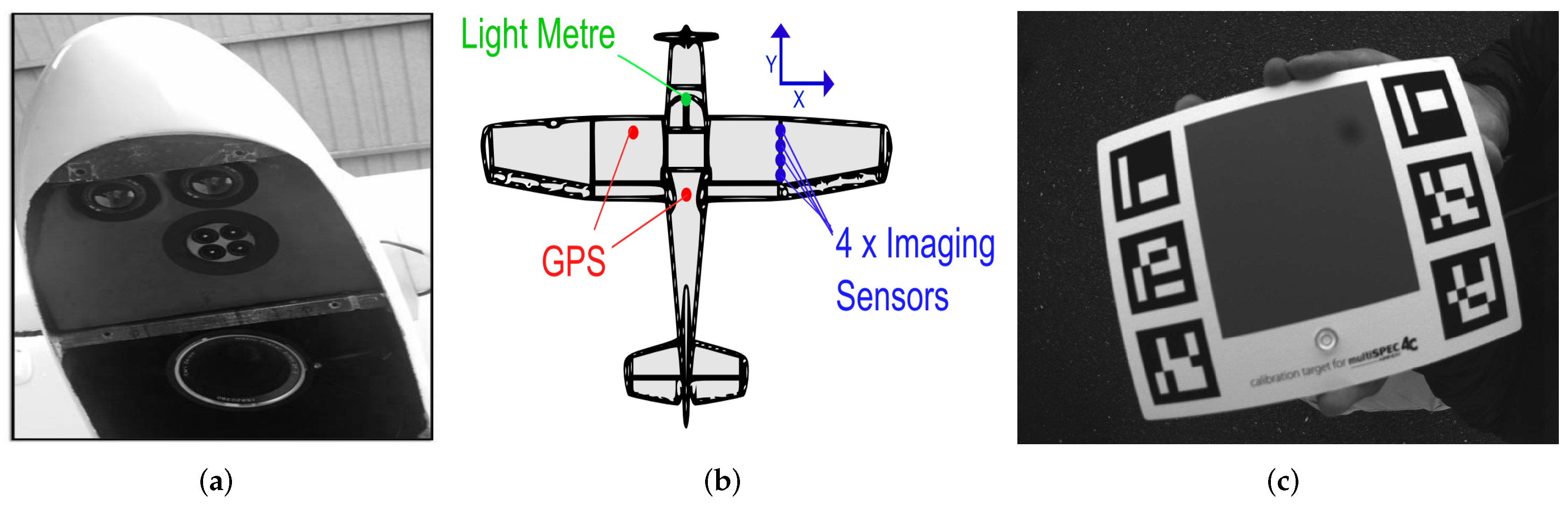
2.2. Sensor Pod
2.3. Sensor Fusion
2.4. Sensor Calibration
3. Methodology
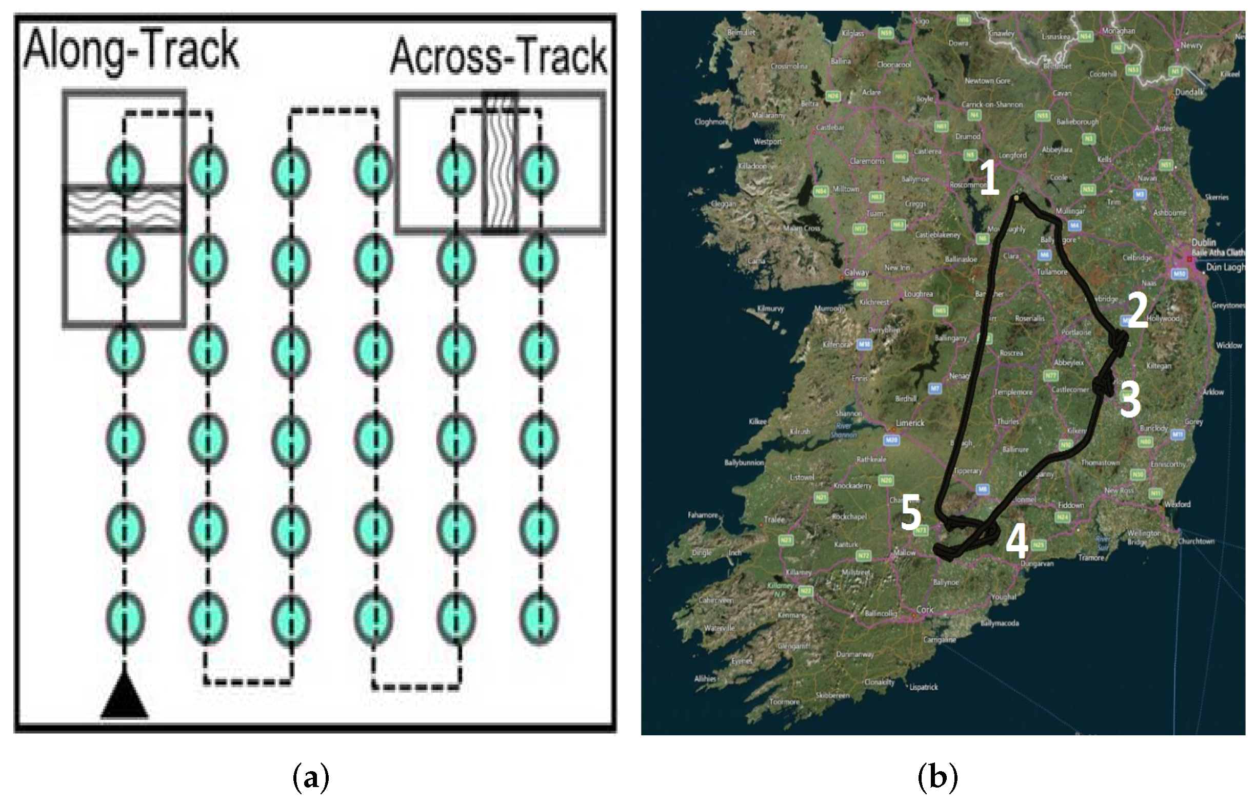
3.1. Flight Planning
3.2. Data Capture
3.3. Image Matching
3.4. Co-Registration of Imagery
4. Results and Discussion
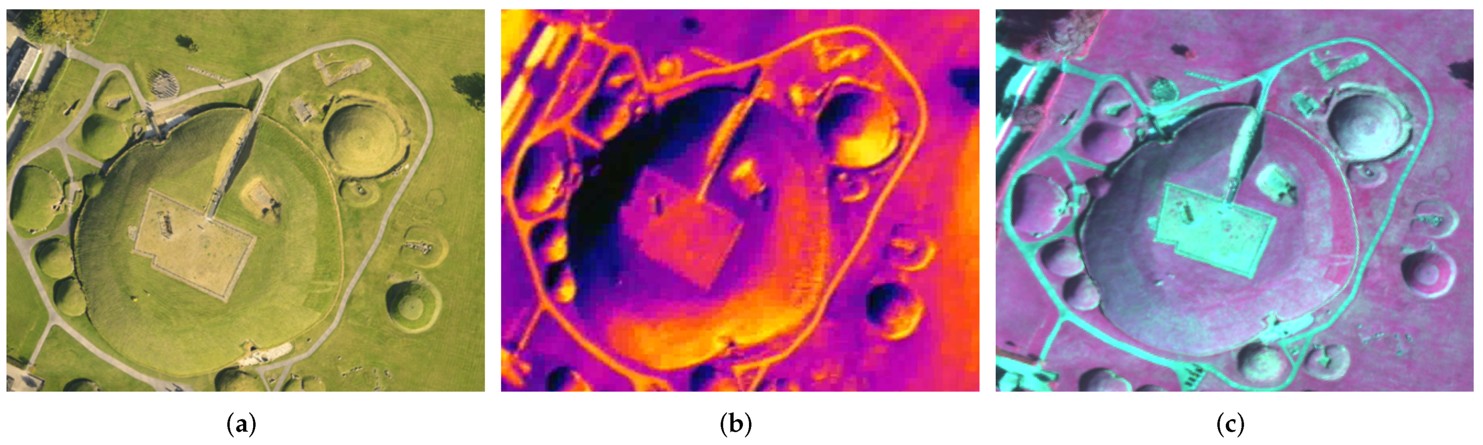
4.1. Sensor Outputs
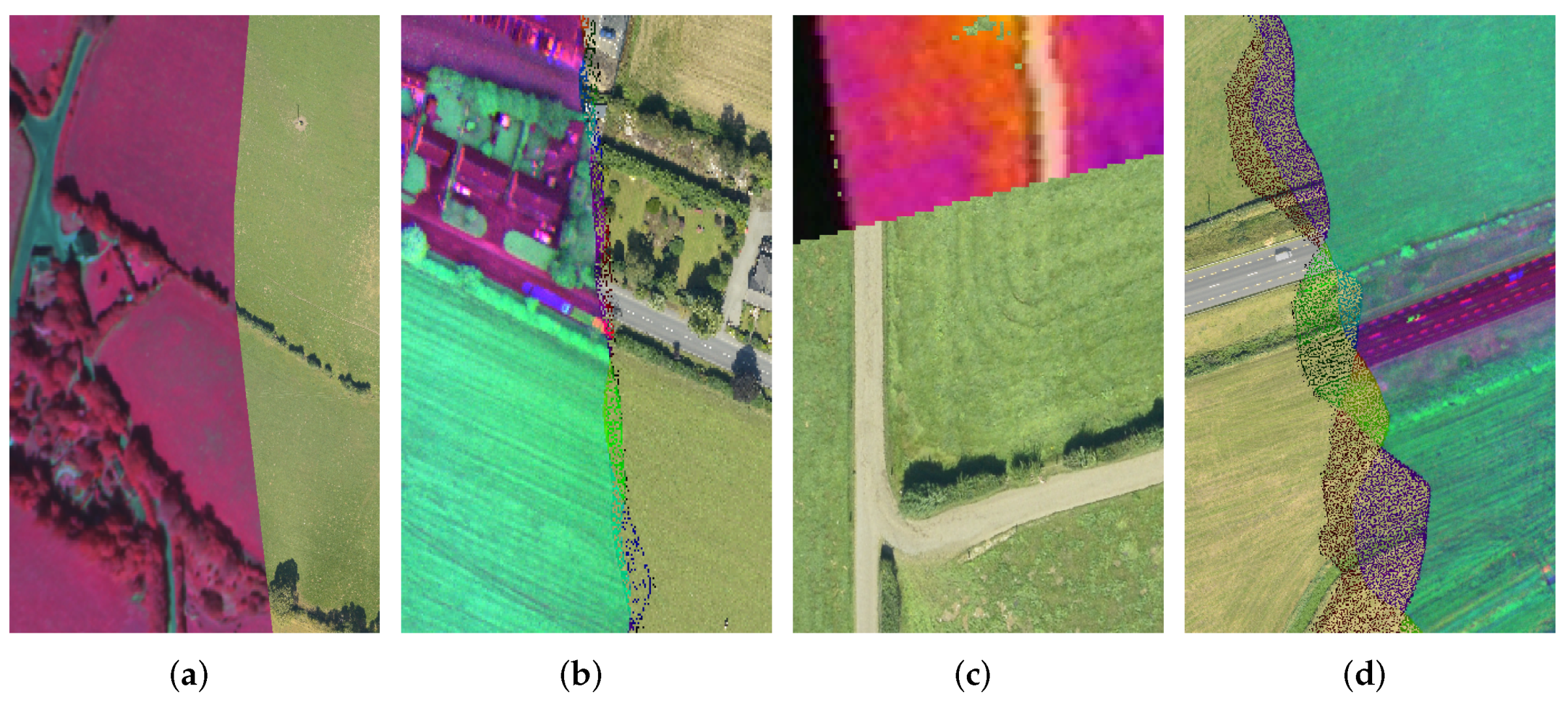
4.2. Sensor Fusion
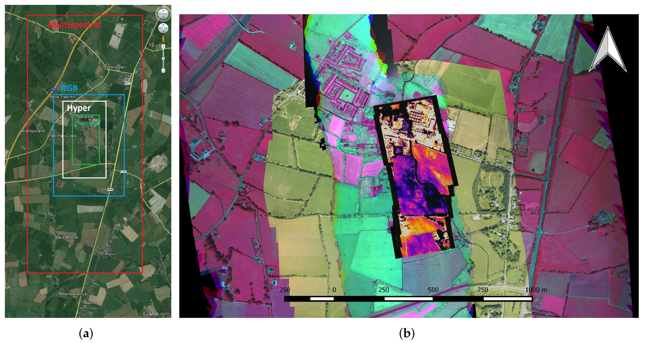
4.3. Spatial Assessment—Absolute Accuracy
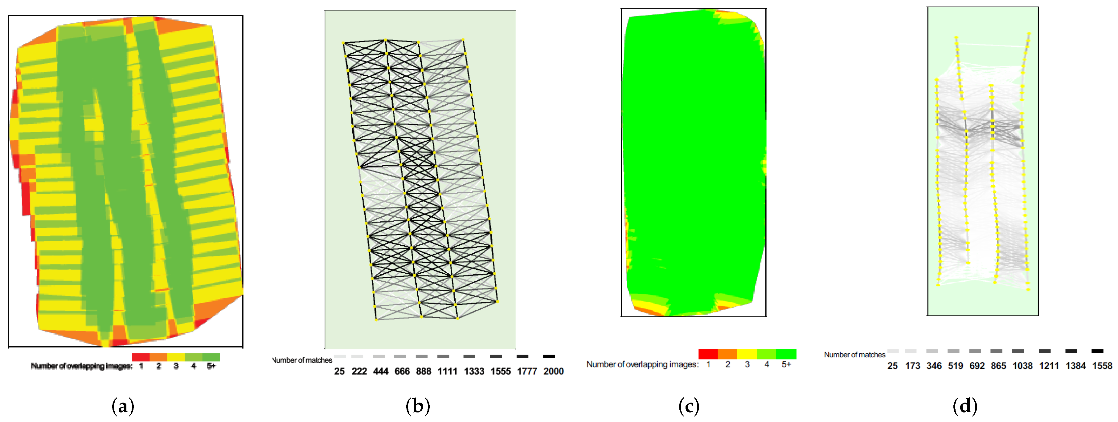
4.4. Spatial Assessment—Relative Accuracy
5. Conclusions
Acknowledgments
Author Contributions
Conflicts of Interest
References
- Noureldin, N.A.; Aboelghar, M.A.; Saudy, H.S.; Ali, A.M. Rice yield forecasting models using satellite imagery in Egypt. Egypt. J. Remote Sens. Space Sci. 2013, 16, 125–131. [Google Scholar] [CrossRef]
- Huang, Y.; Lee, M.A.; Thomson, S.J.; Reddy, K.N. Ground-based hyperspectral remote sensing for weed management in crop production. Int. J. Agric. Biol. Eng. 2016, 9, 98–109. [Google Scholar]
- Atzberger, C. Advances in Remote Sensing of Agriculture: Context Description, Existing Operational Monitoring Systems and Major Information Needs. Remote Sens. 2013, 5, 949–981. [Google Scholar] [CrossRef]
- Liu, Y.; Zhang, B.; Wang, L.-M.; Wang, N. A self-trained semisupervised SVM approach to the remote sensing land cover classification. Comput. Geosci. 2013, 59, 98–107. [Google Scholar] [CrossRef]
- Ghamisi, P.; Dalla Mura, M.; Benediktsson, J.A. A survey on spectral–spatial classification techniques based on attribute profiles. IEEE Trans. Geosci. Remote Sens. 2015, 53, 2335–2353. [Google Scholar] [CrossRef]
- Cai, S.; Liu, D. Detecting Change Dates from Dense Satellite Time Series Using a Sub-Annual Change Detection Algorithm. Remote Sens. 2015, 7, 8705–8727. [Google Scholar] [CrossRef]
- Schulz, J.J.; Cayuela, L.; Echeverria, C.; Salas, J.; Rey Benayas, J.M. Monitoring land cover change of the dryland forest landscape of Central Chile (1975–2008). Appl. Geogr. 2010, 30, 436–447. [Google Scholar] [CrossRef] [Green Version]
- Giri, C.; Pengra, B.; Long, J.; Loveland, T.R. Next generation of global land cover characterization, mapping, and monitoring. Int. J. Appl. Earth Obs. Geoinf. 2013, 25, 30–37. [Google Scholar] [CrossRef]
- Hansen, M.C.; Potapov, P.V.; Moore, R.; Hancher, M.; Turubanova, S.A.; Tyukavina, A.; Thau, D.; Stehman, S.V.; Goetz, S.J.; Loveland, T.R.; et al. High-resolution global maps of 21st-century forest cover change. Science 2013, 342, 850–853. [Google Scholar] [CrossRef] [PubMed]
- Niraula, R.R.; Gilani, H.; Pokharel, B.K.; Qamer, F.M. Measuring impacts of community forestry program through repeat photography and satellite remote sensing in the Dolakha district of Nepal. J. Environ. Manag. 2013, 126, 20–29. [Google Scholar] [CrossRef] [PubMed]
- Monteys, X.; Harris, P.; Caloca, S.; Cahalane, C. Spatial Prediction of Coastal Bathymetry Based on Multispectral Satellite Imagery and Multibeam Data. Remote Sens. 2015, 7, 13782–13806. [Google Scholar] [CrossRef]
- Landsat, Landsat 8 Characteristics. Available online: https://landsat.usgs.gov/landsat-8-history (accessed on 12 January 2017).
- Sentinel 2a, Sentinel 2a Handbook. Available online: https://sentinels.copernicus.eu/web/sentinel/user-guides/sentinel-2-msi (accessed on 12 January 2017).
- Hyperion, Hyperion Datasheet. Available online: https://eo1.usgs.gov/sensors/hyperion (accessed on 12 January 2017).
- Met Eireann, Ireland: Cloud Cover Report. Available online: http://www.met.ie/climate-ireland/sunshine.asp?prn=1 (accessed on 12 January 2017).
- Priem, F.; Canters, F. Synergistic Use of LiDAR and APEX Hyperspectral Data for High-Resolution Urban Land Cover Mapping. Remote Sens. 2016, 8, 787. [Google Scholar] [CrossRef]
- Gholizadeh, A.; Mišurec, J.; Kopačková, V.; Mielke, C.; Rogass, C. Assessment of Red-Edge Position Extraction Techniques: A Case Study for Norway Spruce Forests Using HyMap and Simulated Sentinel-2 Data. Forests 2016, 7, 226. [Google Scholar] [CrossRef]
- Hueni, A.; Damm, A.; Kneubuehler, M.; Schläpfer, D.; Schaepman, M.E. Field and Airborne Spectroscopy Cross Validation—Some Considerations. IEEE J. Sel. Top. Appl. Earth. Obs. Remote Sens. 2016, PP, 1–19. [Google Scholar] [CrossRef]
- Cahalane, C.; McCarthy, T. UAS Flight planning—An Initial Investigation into the Influence of VTOL UAS Mission Parameters on Orthomosaic and DSM Accuracy. In Proceedings of the RSPSoc Annual Conference, Glasgow, Scotland, 4–6 September 2013.
- Rosnell, T.; Honkavaara, E.; Nurminen, K. Geometric Processing of Multi-Temporal Image Data Collected By Light Uav Systems. ISPRS—Int. Arch. Photogramm. Remote Sens. Spat. Inf. Sci. 2011, XXXVIII-1/C22, 63–68. [Google Scholar] [CrossRef]
- Vallet, J.; Panissod, F.; Strecha, C.; Tracol, M. Photogrammetric Performance of an Ultra Light Weight Swinglet “Uav”. ISPRS—Int. Arch. Photogramm. Remote Sens. Spat. Inf. Sci. 2011, XXXVIII-1/C22, 253–258. [Google Scholar] [CrossRef]
- Neitzel, F.; Klonowski, J. Mobile 3D mapping with a low-cost UAV system. ISPRS—Int. Arch. Photogramm. Remote Sens. Spat. Inf. Sci. 2011, XXXVIII, 1–6. [Google Scholar] [CrossRef]
- Primicerio, J.; Di Gennaro, S.F.; Fiorillo, E.; Genesio, L.; Lugato, E.; Matese, A.; Vaccari, F.P. A flexible unmanned aerial vehicle for precision agriculture. Precis. Agric. 2012, 13, 517–523. [Google Scholar] [CrossRef]
- Gómez-Candón, D.; De Castro, A.I.; López-Granados, F. Assessing the accuracy of mosaics from unmanned aerial vehicle (UAV) imagery for precision agriculture purposes in wheat. Precis. Agric. 2014, 15, 44–56. [Google Scholar] [CrossRef]
- Steen, K.A.; Villa-Henriksen, A.; Therkildsen, O.R.; Green, O. Automatic Detection of Animals in Mowing Operations Using Thermal Cameras. Sensors 2012, 12, 7587–7597. [Google Scholar] [CrossRef] [PubMed]
- Riegl, Riegl Bathycopter. Available online: http://www.riegl.com/products/unmanned-scanning/newbathycopter/ (accessed on 12 January 2017).
- Flener, C.; Vaaja, M.; Jaakkola, A.; Krooks, A.; Kaartinen, H.; Kukko, A.; Kasvi, E.; Hyyppä, H.; Hyyppä, J.; Alho, P. Seamless Mapping of River Channels at High Resolution Using Mobile LiDAR and UAV-Photography. Remote Sens. 2013, 5, 6382–6407. [Google Scholar] [CrossRef]
- Husson, E.; Hagner, O.; Ecke, F. Unmanned aircraft systems help to map aquatic vegetation. Appl. Veg. Sci. 2014, 17, 567–577. [Google Scholar] [CrossRef]
- Tomic, T.; Schmid, K.; Lutz, P.; Domel, A.; Kassecker, M.; Mair, E.; Grixa, I.L.; Ruess, F.; Suppa, M.; Burschka, D. Toward a Fully Autonomous UAV: Research Platform for Indoor and Outdoor Urban Search and Rescue. IEEE Robot. Autom. Mag. 2012, 19, 46–56. [Google Scholar] [CrossRef]
- DJI, Matrice 600 Datasheet. Available online: http://www.dji.com/matrice600 (accessed on 12 January 2017).
- DJI, S900 Datasheet. Available online: http://www.dji.com/spreading-wings-s900 (accessed on 12 January 2017).
- Bramor, Bramor c-Astral Safe Operating Parameters. Available online: http://www.c-astral.com/en/products/bramor-geospecs (accessed on 12 January 2017).
- Villa, T.F.; Gonzalez, F.; Miljievic, B.; Ristovski, Z.D.; Morawska, L. An Overview of Small Unmanned Aerial Vehicles for Air Quality Measurements: Present Applications and Future Prospectives. Sensors 2016, 16, 1072. [Google Scholar] [CrossRef] [PubMed]
- Salamí, E.; Barrado, C.; Pastor, E. UAV Flight Experiments Applied to the Remote Sensing of Vegetated Areas. Remote Sens. 2014, 6, 11051–11081. [Google Scholar] [CrossRef] [Green Version]
- UAV Factory, Penguin C UAS Datasheet. Available online: http://www.uavfactory.com/product/74 (accessed on 12 January 2017).
- Irish Aviation Authority, Statutory Instrument 563 of 2015. Available online: https://www.iaa.ie/docs/default-source/publications/legislation/statutory-instruments-(orders)/small-unmanned-aircraft-(drones)-and-rockets-order-s-i-563-of-2015.pdf?sfvrsn=6 (accessed on 12 January 2017).
- Precision Hawk, Precision Hawk DJI Farmer Datasheet. Available online: http://www.precisionhawk.com/DJIFarmer (accessed on 7 December 2016).
- Leica, Leica Aibotix X6 V2 Datasheet. Available online: http://uas.leica-geosystems.us/resources (accessed on 12 January 2017).
- Cahalane, C.; McElhinney, C.P.; Lewis, P.; McCarthy, T. Calculation of target-specific point distribution for 2D mobile laser scanners. Sensors 2014, 14, 9471–9488. [Google Scholar] [CrossRef] [PubMed]
- McCarthy, T.; Fotheringham, A.S.; O’Rian, G. Compact Airborne Image Mapping System (CAIMS). ISPRS—Int. Arch. Photogramm. Remote Sens. Spat. Inf. Sci. 2007, XXXVI, 198–202. [Google Scholar]
- Airinov, Agrosensor Multispectral Camera Specifications. Available online: http://www.airinov.fr/en/uav-sensor/agrosensor/ (accessed on 12 January 2017).
- FLIR, Tau 640 Specifications and Characteristics. Available online: http://www.unmannedsystemstechnology.com/wp-content/uploads/2012/04/FLIR-Tau2-Brochure.pdf (accessed on 12 January 2017).
- McCaul, M.; Barland, J.; Cleary, J.; Cahalane, C.; McCarthy, T.; Diamond, D. Combining Remote Temperature Sensing with in-Situ Sensing to Track Marine/Freshwater Mixing Dynamics. Sensors 2016, 16, 1402. [Google Scholar] [CrossRef] [PubMed]
- Bayspec, OCIUAV 1000 Datasheet. Available online: http://www.bayspec.com/spectroscopy/oci-uav-hyperspectral-camera (accessed on 12 January 2017).
- Vakalopoulou, M.; Karantzalos, K. Automatic Descriptor-Based Co-Registration of Frame Hyperspectral Data. Remote Sens. 2014, 6, 3409–3426. [Google Scholar] [CrossRef]
- Nikon, Nikon D800E Datasheet. Available online: http://cdn-10.nikon-cdn.com/pdf/manuals/dslr/D800_EN.pdf (accessed on 12 January 2017).
- Zeiss, Zeiss ZF2 Datasheet. Available online: https://www.zeiss.com/camera-lenses/en_de/website/photography/what_makes_the_difference/camera_mounts/zf2_lenses.html (accessed on 12 January 2017).
- Aeroscientific, Aeroscientific Flight Planning Software. Available online: http://www.aeroscientific.com.au/ (accessed on 12 January 2017).
- Aviatrix, Aviatrix Flight Mission Software. Available online: http://www.aeroscientific.com.au/Aviatrix-demo-system-overview-Nov14.pdf (accessed on 12 January 2017).
- Prendergast, W.P.; Corrigan, P.; Scully, P.; Shackleton, C.; Sweeny, B. Coordinate Reference Systems. In Best Practice Guidelines for Precise Surveying in Ireland, 1st ed.; Irish Institution of Surveyors: Dublin, Ireland, 2004; pp. 17–20. [Google Scholar]


| Sensor | Hfov | Vfov | Footprint | GSD | Spect. Range | Bands |
|---|---|---|---|---|---|---|
| AgroSensor | 74 | 51 | 33.2 ha | 0.52 m | 0.53–0.83 m | 4 |
| Tau 640 | 25 | 20 | 3.93 ha | 0.35 m | 7.5–13.5 m | 1 |
| OCI-UAV-1000 | 38 | 20 | pushbroom | 0.17 m | 0.6–0.9 m | 100 |
| Nikon D800E | 39.6 | 27 | 8.59 ha | 0.07 m | Visible | 3 |
| Sensor | RMSE (m) | Mean (m) | Std. Dev (m) |
|---|---|---|---|
| Multispectral | 12.43 | 9.66 | 8.57 |
| Thermal | 15.70 | 13.5 | 8.78 |
| Hyperspectral | 13.15 | 9.83 | 9.57 |
| RGB | 11.26 | 8.83 | 7.65 |
| Test | Site | OSi (ha) | Multispec (ha) | Thermal (ha) | Hyperspec (ha) | RGB (ha) |
|---|---|---|---|---|---|---|
| 1 | Field | 5.81 | 5.79 | 5.72 | 5.67 | 5.63 |
| 2 | Field | 1.39 | 1.37 | 1.33 | 1.33 | 1.35 |
| 3 | Field | 1.55 | 1.70 | 1.72 | 1.65 | 1.52 |
| 4 | Plant | 1.22 | 1.35 | 1.55 | 1.37 | 1.22 |
| 5 | Farmyard | 0.35 | 0.35 | 0.32 | 0.50 | 0.37 |
© 2017 by the authors; licensee MDPI, Basel, Switzerland. This article is an open access article distributed under the terms and conditions of the Creative Commons Attribution (CC BY) license (http://creativecommons.org/licenses/by/4.0/).
Share and Cite
Cahalane, C.; Walsh, D.; Magee, A.; Mannion, S.; Lewis, P.; McCarthy, T. Sensor Pods: Multi-Resolution Surveys from a Light Aircraft. Inventions 2017, 2, 2. https://doi.org/10.3390/inventions2010002
Cahalane C, Walsh D, Magee A, Mannion S, Lewis P, McCarthy T. Sensor Pods: Multi-Resolution Surveys from a Light Aircraft. Inventions. 2017; 2(1):2. https://doi.org/10.3390/inventions2010002
Chicago/Turabian StyleCahalane, Conor, Daire Walsh, Aidan Magee, Sean Mannion, Paul Lewis, and Tim McCarthy. 2017. "Sensor Pods: Multi-Resolution Surveys from a Light Aircraft" Inventions 2, no. 1: 2. https://doi.org/10.3390/inventions2010002