Review

Effect of Load Changes on Hybrid Shipboard Power Systems and Energy Storage as a Potential Solution: A Review

by
Viknash Shagar
*,
Shantha Gamini Jayasinghe
and
Hossein Enshaei
Australian Maritime College, University of Tasmania, Launceston TAS 7250, Australia
*
Author to whom correspondence should be addressed.
Inventions 2017, 2(3), 21; https://doi.org/10.3390/inventions2030021
Submission received: 20 July 2017 / Revised: 9 August 2017 / Accepted: 11 August 2017 / Published: 28 August 2017

Abstract

:
More electric technologies (METs) play an important role in meeting ever-growing demands for energy efficiency and emission reduction in the maritime transportation sector. As a result, ships with electrical power transmission are becoming popular compared to traditional mechanical power transmission based ships. Hybrid electric propulsion is an intermediate step in this trend where both mechanical and electrical propulsion technologies are combined to get the benefits of both technologies. In this arrangement, not only the propulsion loads but also non-propulsion loads are connected to a common electrical power bus that could lead to serious power quality issues due to disturbances such as large load changes. This paper presents a comprehensive review on energy storage-based solutions that have been proposed to reduce their effects. The important aspects of existing as well as emerging energy storage control techniques and challenges in reducing transient effects in hybrid shipboard power systems with the use of energy storage are discussed in the paper.

Graphical Abstract

1. Introduction

Technology advancements have affected many sectors in today’s world and the shipping sector is no exception. Electrification of the ship is a key component of this as the ships of today have a higher power demand and have loads that are highly variable in nature. In addition, shipping companies are under growing pressure to comply with emission regulations, especially when entering emission control areas (ECAs) [1]. Therefore, following the trend in the automobile industry, hybrid electric ships, as an intermediate step towards all-electric ships, have emerged as an alternative to fill the need to reduce emissions caused by the ships of today. In hybrid electric ships, the traditional mechanical propulsion is combined with electrical propulsion for fuel efficiency thereby reducing emissions. Even though the retrofitting requires an initial investment, it can be compensated through the reduced cost of operation in the long run.
However, there is a noticeable gap in the knowledge of hybrid ships, especially in the electrical aspects of hybrid ships, such as understanding the behavior of the shipboard electric system (SES) in various operating conditions and severe load transients. Hence, the existing problem that has been identified are the large variations in power demand and hence the voltage and frequency fluctuations in the shipboard power system that occur in transient conditions when there are frequent and large amounts of load changes added to the network. This issue of voltage and frequency transients onboard mechanically driven or electric ships due to these load changes have been widely discussed in the literature [2,3,4,5]. However, this effect has not been sufficiently studied in hybrid propulsion-based shipboard power systems. This problem has been made more complex due to the fact that such power systems can operate in multiple modes due to the flexibility in using either mechanical, electrical or both kinds of propulsion according to the operational needs. However, there has been ample evidence in the literature to suggest that energy storage can be a viable option to reduce these transients in a power system for other related applications. An effective control system for energy storage elements has the potential to counter the effect of load changes to a large extent [6,7,8,9,10,11]. This paper reviews the possible energy storage control systems that can be adopted onto ships to reduce the transient conditions in the shipboard power system due to load changes. This is particularly applicable to hybrid propulsion electric ships as their electrical system behavior has not been documented widely in the literature.
The following section gives an overview of shipboard power systems and the different architectures that are used in electric ships and the functions of the different components of the system that can potentially be used in hybrid propulsion ships. Section 3 describes the nature of loading conditions of ships and its effects on system voltage and frequency. It discusses the existing shipboard voltage and frequency control and also explores the potential for energy storage control techniques as a solution to mitigate the voltage and frequency fluctuations due to the transients caused by changing loading conditions. Section 4 introduces some thoughts on the challenges that might be encountered in implementing energy storage solutions onboard ships. Finally, Section 5 provides the summary and conclusion for this review.

2. Shipboard Power Systems Overview

The most common configuration of the shipboard power network is the radial power network where multiple generators supply power to switchboard panels, which subsequently are connected to the distribution system that serves most loads [12,13]. This has been used traditionally in both mechanically driven ships as well as in the electric ships. High Voltage (HV) equipment like large motors for pumps or propulsion are directly connected to the main switchboard or connected through step down delta-connected transformers. A floating delta configuration is essential for the transformer to increase survivability after the first single line to hull fault, loss of one phase of a transmission line or one leg of transformer winding. These, together with weapons systems, emergency lighting and communications are termed as the essential loads. Step down transformers connect the 6.6 kV HV switch board to the 440 V Low Voltage (LV) switchboard. LV equipment such as those used for lighting and other hotel loads are non-essential loads and are usually connected via the LV switchboard. A typical schematic for a shipboard radial power system of a ship employing electric propulsion as explained in [14] is shown in Figure 1a.
Modern shipboard power systems are moving towards the Zonal Electrical Distribution System (ZEDS). This system could have an AC or a DC main bus. An illustration of the AC zonal electrical distribution system (ACZEDS) and DC zonal electrical distribution system (DCZEDS) are shown in Figure 1b,c respectively. An ACZEDS system would be similar to DCZEDS except that there would not be any AC–DC rectification from the AC sources into the main busbar. The main advantage of the ZEDS configuration is that it compartmentalizes the power system into separate zones thus improving reliability in the event of a fault in any section of the system. Also, faults can be easily identified and isolated in a ZEDS through the use of local zone-based and global system-wide communication and protection networks that coordinate information between different zones.
The hybrid electric ship power system configuration [15,16] was developed to combine the advantages of both electrical and the mechanical propulsion so as to supply power efficiently when there is a big variation in the power demand especially during maneuvering operations. Hybrid ships provide better energy efficiency and a reduction in emissions. Due to multiple energy sources, although the existing recommended level of redundancy is preserved, the reliability of the propulsion system is improved due to using two different propulsion systems that have a lesser chance of failing due to the same technical problems while ensuring better efficiency. A typical power generation and distribution system of a hybrid ship is depicted in Figure 1.
Hybrid shipboard power system configuration can be classified as serial or parallel in nature as illustrated in Figure 2a,b. In the former, the combustion engine and electric systems are in series and there is no direct mechanical connection between the engine and the propeller. The propulsion is only done by a variable speed electrical drive. Energy storage can be connected to the electrical drive. This improves the global efficiency of the system by optimizing the operating point of the combustion engine and the propeller. In the parallel configuration, the electric motors and combustion engines are mechanically joined using clutches and gearboxes by the same shafts. The electric motors are supplied by energy storage or other independent power sources. Hybrid vessels are already being tested for use in passenger ferries such as the Nemo H2 in Amsterdam and the tugboat RT Adrian in Rotterdam [15].
Current literature [5,17] has covered various modes of operation that are possible for a hybrid ship electric system with a parallel architecture as shown in Figure 2b. It is worth noting that usually the main (diesel) engine provides mechanical propulsion but auxiliary electrical generators which usually have a smaller capacity as compared to the main engine can also give power for electrical propulsion. A shaft machine connected to the electric generator and main engine can act either as an electric motor or an alternator according to the power demand of the hotel and propulsion loads. The most common modes of operation are outlined as follows.
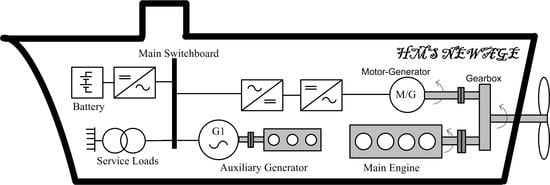
  • Boost or Power Take In (PTI) Mode—Main Engine and Auxiliary Generators supply power to hotel and propulsion loads. Shaft machine acts as a motor to drive the propellers.
  • Parallel Mode—Power demand is more than that of the capacity of auxiliary generators but less than that of the main engine. The main engine thus runs at partial load and supplies power for hotel loads and propulsion with one auxiliary generator also supplying power to hotel loads. Shaft machine acts as an alternator and supplies electrical energy.
  • Transit Mode or Power Take Out (PTO) Mode—Only the main engine supplies power to propulsion and hotel loads. Shaft machine acts as an alternator.
  • Shore Connection or Cold Ironing Mode—Only port supply satisfies ship’s power demand.
  • Power Take Home (PTH) Mode—Main Engine fails. Auxiliary Generators supply power for hotel and propulsion loads. Shaft machine acts as a motor.
  • Hybrid Mode or PTO/PTI Mode—Shaft machine acts as an alternator or motor in order to maintain shaft machine and main engine RPM in the range of 70–100% of full load to increase their efficiencies.

3. Loading Conditions and Its Effects on the Shipboard Power System

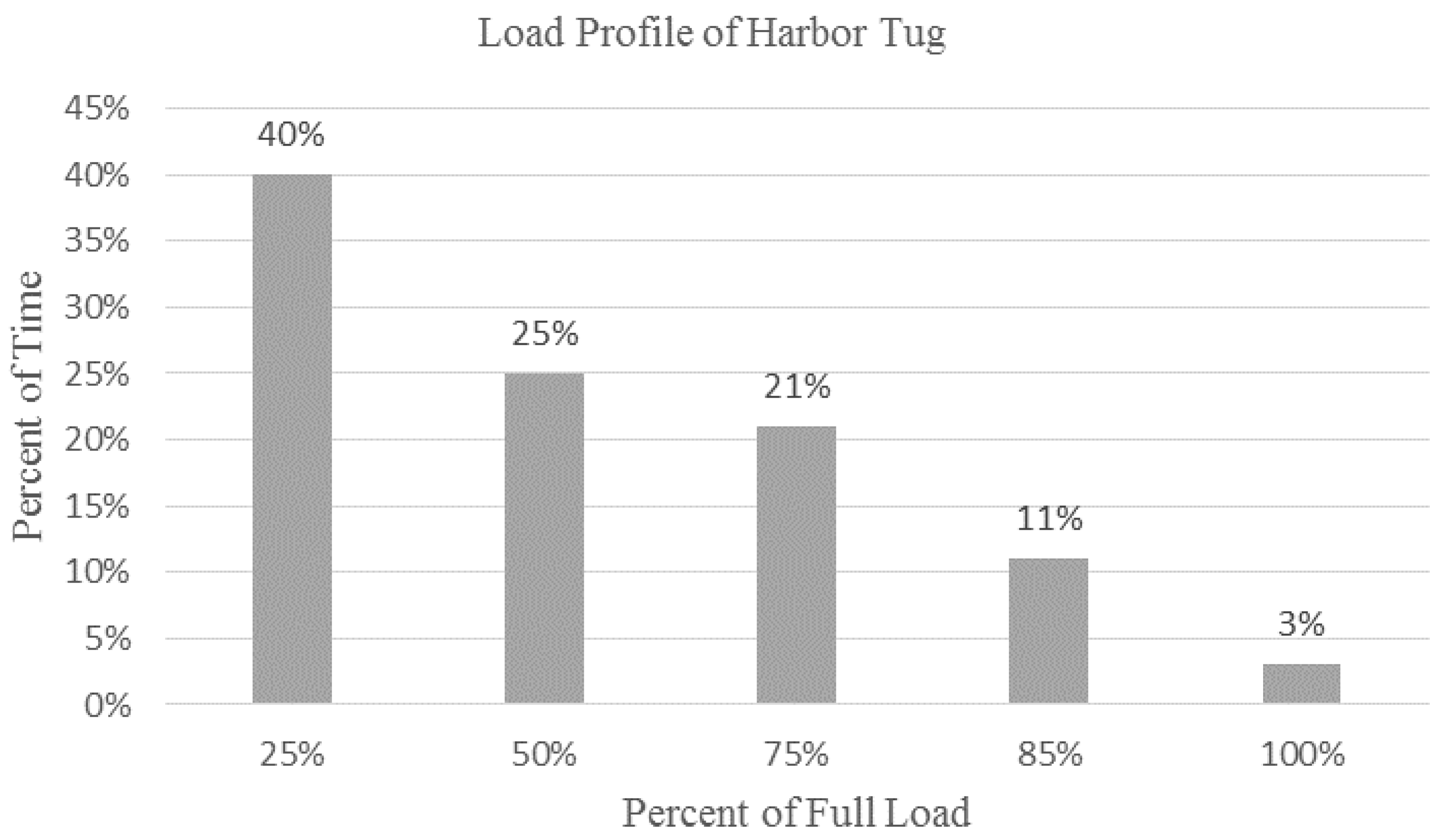
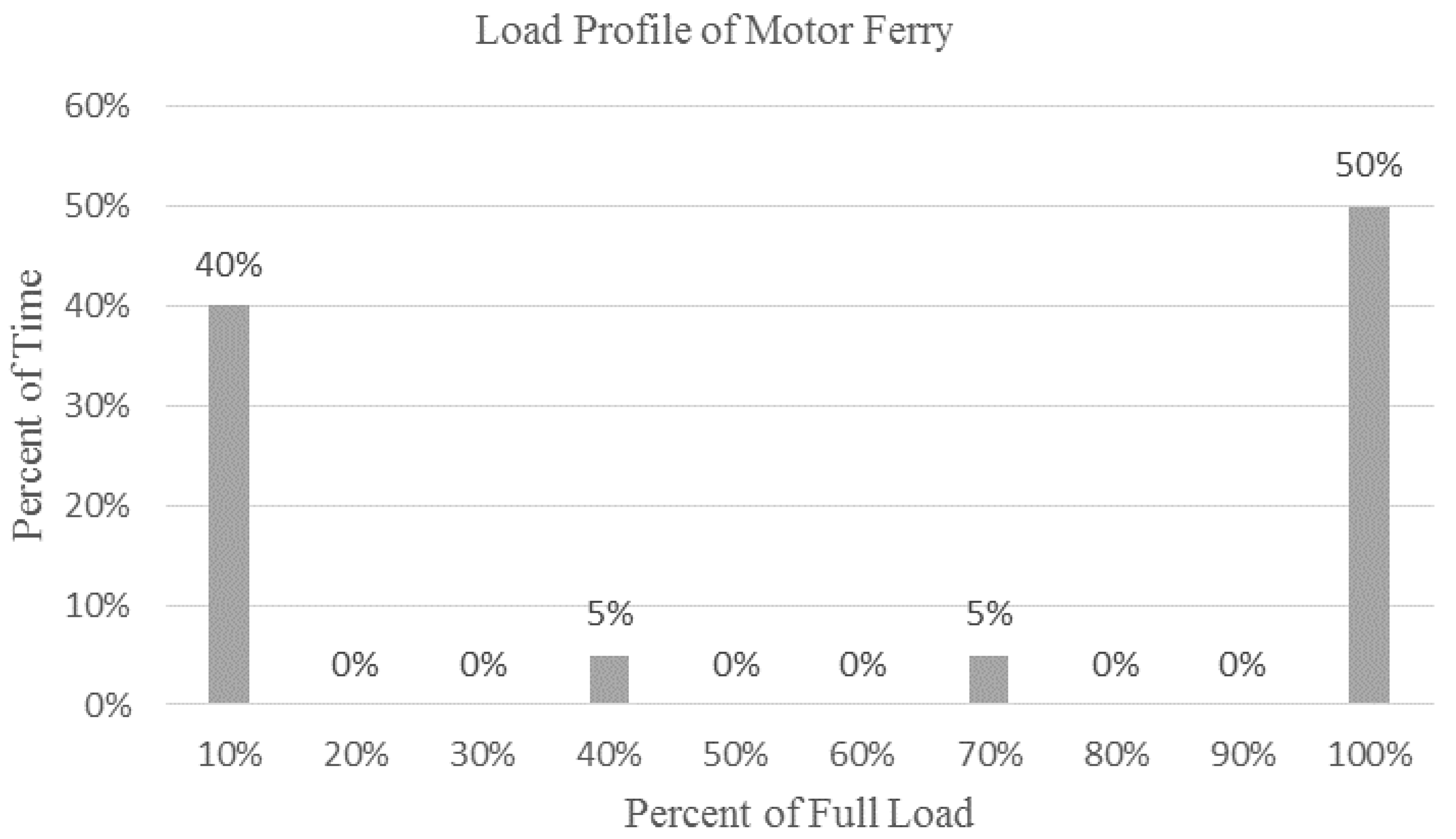
3.1. Loading Conditions of Ships

Knowledge of loading conditions is essential for any investigation on shipboard operation as it can determine the particular mode of operation that is optimal in terms of cost and efficiency. This is of great importance for Hybrid Ships due to the presence of various supply configurations mentioned above. Out of the various loads present in a ship, the propulsion load is the most dominant. This includes loading from heave compensators, wave induced thruster disturbance, thrust loss due to ventilation and interaction between thrusters [17]. Propeller load modeling is complex and is often specific to factors such as the number and design of propellers, hull design, wind strength, amount of exposure to air above the sea level and other environmental factors. However, existing literature [18,19,20] outlines algorithms that determine the resistive force needed to be overcome by the propellers for ship motion. This resistive force is assumed to be the propeller loading, which depends on the waves as they have the most effect on a ship at sea.
The Douglas sea scale is used to classify the state of the sea based on the height of the waves. The thrust, RT, needed for the baseline case of calm sea conditions based on the total ship resistance is to be calculated by Equation (1).
R T = 1 2 C T ρ S V 2
where CT is the coefficient of resistance for calm waters, derived by performing Computational Fluid Dynamics analysis on the hull form of a ship, V is the ship velocity, ∇ is the displaced volume, S is the wetted surface of the hull that is dependent on the draught amidship, T, and the waterline length of the ship hull is denoted as Lwl. A rough guide to the calculation of S for the different kinds of ships [20] is displayed in Table 1. Resistance on the propellers for calm waters is then calculated. This value varies as the square of the amplitude of the waves. Therefore, for any profile of wave conditions at sea expressed in terms of its height, the force exerted on the propeller for each discrete time interval can be calculated, summed up and averaged to determine the approximate mean propulsion loading on a ship. The power needed for the propellers can also be calculated, as it is proportional to the cube of the ship velocity.
In addition to the propulsion loads of a ship, there exist other loads such as the hotel loads and reefer loads. An example of a complete load profile of a ship [14] that takes into account all the different types of loads [14] is the Post Panamax container carrier when at sea for 75% of the time in a year is shown in Figure 3 and Table 2. Note that ME refers to Main Engine while CSR is defined as the Continuous Service Rating, which is taken to be 90% of the maximum continuous power rating. The bar chart plots the Percentage of running hours against the Main Engine load. The exemplary load profiles of a harbor tug with two forward thrusters supplied by a 2040 KW diesel engine that tows container ships is shown in Figure 4 while that of a passenger motor ferry with a 50 KW service load and driven by 2 × 470 KW gas engines that does a 40-min to and fro journey [21] regularly is as below in Figure 5. It is observed that the load variation has a more evenly balanced distribution approaching a typical normal distribution in the case of the container ships while smaller vessels such as tugs and ferries have a more skewed profile. This could be due to larger container ships undertaking longer journeys where the loading conditions are more numerous and random while smaller vessels undertake frequent and repetitive operations near the port or along a river. Also, extreme operating conditions are more prominent in the smaller vessels such as the tug and ferry as compared to container ships. This could be attributed to the long periods in oceanic voyages where container ships travel at a set speed with about close to 50% redundancy in power capacity while smaller ships operating closer to land have a higher proportion of activities that consume very high or a very low proportion of total power capacity such as berthing or maneuvering.
Another feature of the loading profile is that the load or the power demand profile of a ship can vary very quickly in a matter of minutes at sea because of the constantly changing environmental conditions influenced by the wind, wave and current. A typical load power demand and bus bar frequency profile, despite applying thruster power management algorithms and thruster speed control techniques can change by as much as about or 40% of the nominal power in less than 10 s after employing power management algorithms [22]. The electrical frequency of the system can change by as much as 7% within 5 s under speed control, which in most cases is unacceptable for proper operation of sensitive loads connected to the system [22]. This highlights the need for further measures to be implemented in order to ensure that the voltage and hence the power as well as the frequency can be better controlled with lesser variation during load changes.
Once a ship is in harbor, there is a power demand for cargo operations as well as for some hotel loads on board. Some ports provide shore power connection at their berths while others do not, in which case, the ship has to plan to provide the required power. For example, the port of Los Angeles provides shore-side electrical power to the ships at its berth in order to reduce the emissions that might arise if the ships were to run on their diesel power. The average energy consumed by the different types of vessels berthed at the port [21] is summarized in Table 3 below.
It has also been found that a container ship can use as much as 4 MW of shore power at the berth. However, this is likely to be influenced by the size and amount of cargo operations required for the ship. The corresponding figures for Reefer ships, Ro-Ro ships, tankers and Bulk cargo ships are on average, 2 MW, 0.7 MW, 5 to 6 MW and 0.3 to 1 MW [21].

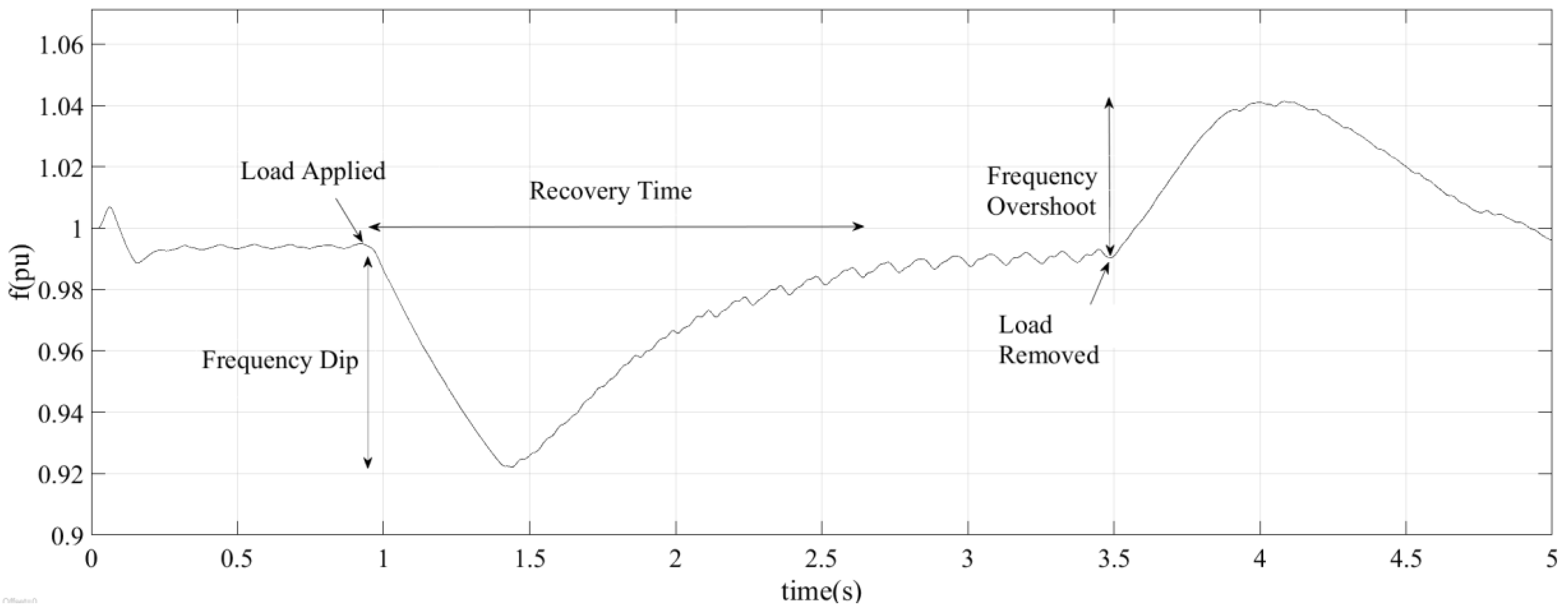
3.2. Load Changes and Its Effects for the Shipboard Power System

There is always a narrow range of values within which the frequency and voltage in a power system is allowed to vary despite any external disturbances such as load changes. Adding and removing the load from a power system causes transients that results in these parameters going beyond this range for some time period. Another important factor that influences the transient magnitudes is the time to start up the engines for the propeller and the ship. The start up time of the propeller can be between 1 to 60 s and that of the ship run up time is between 60 to 500 s. Electric machine dynamics have time constants between 1 ms to 1 s and thus their ability to cope with sudden load changes have a huge impact on the power system transient conditions. In addition, the type of shipboard power system configuration as covered in Section 2 and the distance and location of the load from the sources can also influence the magnitude of transients experienced [23]. Figure 6 illustrates an example profile of system parameters fluctuations such as those of frequency that can occur due to load addition and removal. Conventional control measures to reduce these fluctuations as described in Section 3.3, act after a delay to bring these parameters back to the acceptable range. However, in doing so, an over shoot is often observed and again the feedback system attempts to bring down the values resulting in a momentary dip. These oscillations continue for a period of time called the recovery time or settling time before the values settle within the acceptable range. The converse happens when a load has been removed from the system. It is obvious from the figure that the amplitude of the over shoot and dip as well as the length of the settling (recovery) time has to be reduced for a better transient response to load changes. The ideal response would be one where the frequency or voltage transients are virtually non-existent. The next paragraph explains in further detail how transients are created when a power system experiences a load change.
When a load has been applied, the speed regulator of the engine of the generator injects more fuel into the cylinder but since the amount of air is not yet increased, the combustion is not complete and the frequency of the engine continues decreasing till the engine outlet temperature and air pressure increases at which point, torque production becomes more efficient and the frequency starts increasing. This process may take up to a few seconds till the frequency is stabilized. An increase of load in shorter period of time will result in a higher frequency dip. This is due to the limitation in the development of the mechanical torque as the rate of increase of the load becomes very high. When there is a load reduction, the fuel injection into the cylinder reduces but due to the large amount of air mass still remaining, the combustion is complete and the frequency deviation is usually smaller than the case of a load increase. Frequent load fluctuations can result in a rise in the thermal load of the system because the air pressure decreases faster than it rises. This heating effect can result in burnt exhaust valves and hot corrosion. The voltage from a generator decreases when a sudden load is added and increases when a load is suddenly removed from the power network. Although the generator excitation system acts to restore the voltage to its nominal value, there is still a delay because of the response time of the Automatic Voltage Regulator in the excitation system to act during which period, the voltage will be fluctuating. Other factors that affect the voltage stability after a load change are the load current, power factor, generator transient and sub-transient reactance of the generator [3]. Such frequency and voltage transients result in inferior power quality for the system, which affects the operation of other loads connected to the same power network and can cause overheating of equipment thus presenting a fire hazard. There have been real-life instances of ships that suffer from such issues due to load changes. In [16], the negative effects of long- and short-term deviations of frequency and voltage of shipboard power systems have been described. These can include overheating and energy losses as well as equipment malfunction. A case study of a ship with significant voltage dips highlights this issue. It was found that this only happens when the ship pulls in and out of port. Further investigation reveals that the inrush current during the starting up of a thruster motor during that ship operation has been the cause. The starting up of the thruster motor was necessary in order for the ship to perform maneuvering operation so as to navigate safely into or out of the port.
A similar issue for isolated power systems such as that of a ship has been discussed. Experimental results show that direct starting of induction motors which might be used for propulsion needs on board a ship can lead to an inrush current several times that of the rated value that can result in a voltage dip of up to 25% which is unacceptable for normal operation of other appliances connected to the power system. Conversely, disconnection of motor loads can mean a 25% voltage overshoot of the grid voltage. Transient fluctuations of the system frequency have also been observed in both instances of adding and removing motor loads. If there are multiple motors to be started, since the starting torque of a motor is proportional to the square of the terminal voltage, a dip in the voltage due to other motors or other loads means that the motor takes a longer time to reach the required speed [24]. The excessive current flow during this prolonged period of time will lead to a further voltage drop and overheating. This chain effect might eventually lead to tripping of the motor(s). However, there are various existing conventional solutions to deal with the start-up effects of thruster motors in addition to inbuilt conventional control measures in the generator to deal with these voltage and frequency fluctuations. These will be described in the following section.
There are standards defined by various bodies to stipulate the limits of the electrical parameters which if violated could lead to the above mentioned effects that could occur due to voltage and/or frequency dips. These standards could be applied as a general guideline to shipboard power systems as well. The IEC [22] defines tolerance limits for voltage and frequency dips and spikes for both steady state as well as transient conditions. This is shown in Table 4.

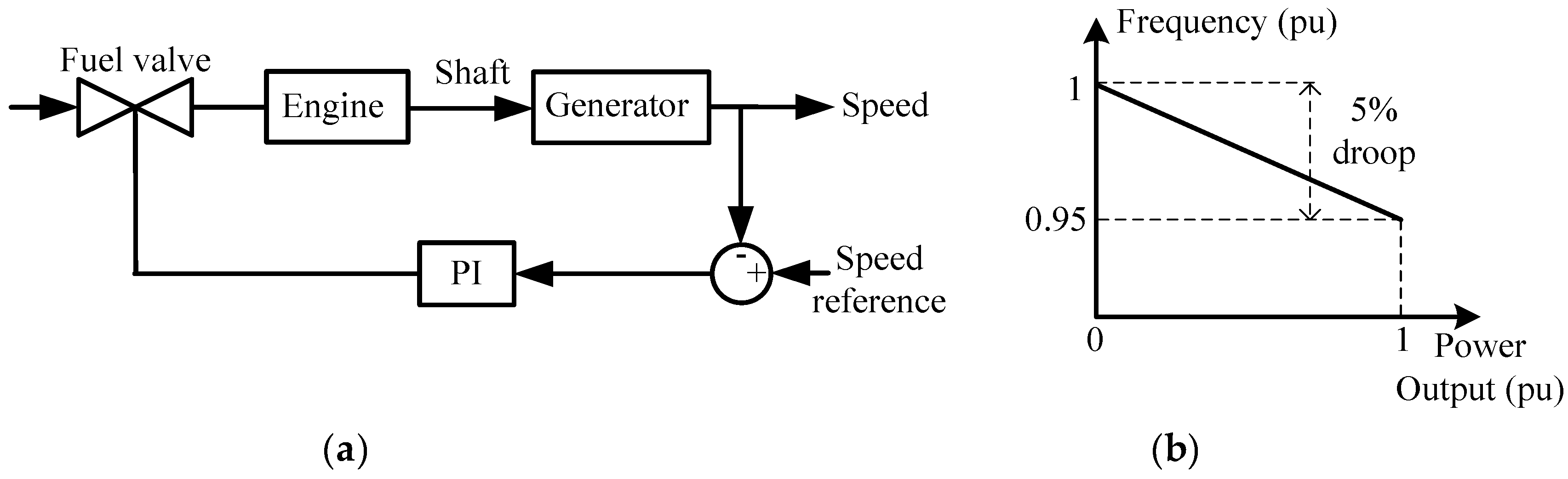
3.3. Conventional Shipboard Voltage and Frequency Control

The voltage and frequency of a power system is usually set by the generating sources. In a generator, the Excitation System controls the generator output voltage. It limits the magnitude of voltage dip or voltage rise to a fixed period of time. Typically, voltage change of 15% or less is usually brought back to nominal value within about 1.5 s [25]. The excitation system depends on an AC or DC exciter source to create a strong magnetic field at the field windings of the rotor when a DC current passes through it. The stator produces the generator terminal voltage when it cuts through the magnetic field of the rotating rotor. There is a feedback loop with an Automatic Voltage Regulator (AVR) where the generator output is measured and if there is a change from the nominal value, the field current is altered to maintain the voltage. Flexible AC Transmission System (FACTS) devices have also been traditionally used in power systems as voltage mitigation measures. FACTS devices principally use power electronic passive devices such as inductors and capacitors and active devices such as switches in various configurations to inject active or reactive power as needed to reduce the voltage error from the nominal value. Examples of FACTS devices are Static Synchronous Compensators and the Unified Power Quality Conditioner [26,27,28].
In multi-generator systems, frequency control is usually implemented by the droop speed control settings of a generator. The frequency droop characteristic of a generator dictates that the system frequency drops as the active power of the system increases. The difference between the actual speed and the speed reference is used to increase the flow of fuel or steam into the prime mover so that the power output is increased. For a 100% change of the power loading of the generator of the system, the frequency at full load drops by a specific percentage from its no-load frequency. This percentage value is the droop setting value of the generator. The change in power output counteracts frequency fluctuations and allows the unit to settle into a steady state point in the droop characteristic. Droop control allows each of the generators that might have different speed settings to share a portion of the load without “fighting” for control over the load otherwise known as load hunting. Figure 7a shows a schematic of droop control implementation in a generating source [25] while Figure 7b gives an example of a droop characteristic with a droop setting value of 5%. The start-up current of thruster motors is a key cause to transient conditions on the shipboard power system. Different combinations of options such as Direct-On-Line starting, Wye/Delta starting and a combination of autotransformer and capacitors are possible solutions to reduce the start-up current of squirrel cage motors in thruster motors as have been considered in [29]. However, these solutions, while reducing the starting currents of motors, do not eliminate the voltage and frequency fluctuations that come with adding or removing motor loads from the power network.
Another key reason for voltage and frequency fluctuations in ships is the increasing proportion of loads that have a very short start up time. These are usually weapon loads or emergency service loads that demand a huge amount of power acting for a very short period of time. Pulsed loads have been added to two kinds of shipboard systems, which are that of the ferry and the Liquid Natural Gas (LNG) carrier. The step load nature of application of pulsed loads is another major cause of transients in ships. Conventional Proportional-Integral (PI)control solutions have been implemented on their ability to keep the voltage and frequency fluctuations down. Load dump tests in steps of 25% have been done in [18] to simulate load changes on board a ship with a 2-steam turbine generator system. A two-layered control have been proposed by the authors to reduce frequency fluctuations. An adaptive P controller has been used as a primary frequency controller in order to deal with large frequency deviations. The second layer of control is the classical PI controller that aids in achieving the zero steady state error and provide identical power to both the units. The delay time between the actions of the two layers of control has also been optimized. Reference [30] analyzes the stability of the rotor angle, frequency and voltage parameters of the MVDC network in an electric ship. The latter two parameters are directly related to the balance between power demand and power supply. The stability of the system has been mathematically defined. Different load side as well as generator side control techniques for stabilization of constant power loads fed by a DC/DC converter are analyzed. These include adding stabilizing state feedback on each individual load side converter and using active damping implementation on converters’ interface to improve stability.
The effect of pulsed load on the frequency modulation of a ship electric network has been explored in [31]. The expression for the frequency modulation has been derived as a function of pulsed load period, generator inertia, frequency droop and frequency controller gain. Each of these factors has been varied to investigate their effect in keeping the frequency fluctuation, active and reactive powers of the pulse load within limits. The study has been repeated for modulation of the voltage in the event of pulsed loads in [32]. Here, the impact of the Automatic Voltage Regulator (AVR) gains, generator reactance cable reactance, base load and the pulsed load duty cycle in keeping the voltage variation within limits have been determined. This study gives the opportunity for optimization of the parameters to limit the transient effects of load changes on the key electrical parameters such as voltage and frequency.
There has been literature published in the area of load changes for the shipboard power system. However, the majority of them have focused solely on the thruster loads, neglecting the hotel and ship service loads that make up the total electrical load of any ship. Also, while there have been studies of the detrimental effects of thruster motor start-up on the voltage and frequency of the system, the effect of changing sea and wind conditions leading to frequent changes of the steady state load has not been explored fully in good detail. It has also been found in this section of the literature review that often, separate control strategies have been used to control the voltage and frequency fluctuations of the ship arising from load fluctuations. It might be more efficient from a control perspective to have a single control system to manage both of the parameters. Energy Storage solution is one such system where the active and reactive power supplied by the Energy Storage sources can be simultaneously controlled. Due to their additional capacities, they can also be used to reduce the reserve margins of the existing generation sources in the system. Energy storage has been widely studied in the Renewable Energy sector as such sources can be used to smoothen the system parameter fluctuations that occur due to the varying nature of power available from Renewable Energy Sources such as wind or solar power. The control strategies used in regulating the power and frequency to the grid in renewable power system applications could be applied with appropriate modifications to shipboard power systems that experience variable power demand conditions at sea due to the harsh environmental conditions or even the need for special applications such as weapons. The control solutions of these systems will be covered in the following sub-section. Also, other novel control techniques used in other areas of Power Engineering will be reviewed for potential application in the hybrid shipboard Energy Storage control system.

3.4. Energy Storage Systems

3.4.1. Energy Storage Devices

Energy storage has been reported in the literature as a means to improve the power quality of a network and increase the reliability of the system due to the additional energy capacity that can be supplied to the network when needed. Additional energy might be needed for a variety of reasons such as to meet fluctuating power demands, smoothen power supply from intermittent sources and improving the voltage and frequency profiles that have been distorted due to transient conditions. The types of energy storage used in shipboard power systems can be broadly classified into 4 types. They are electrochemical devices that include batteries, electrostatic devices such as supercapacitors, electromechanical devices of which the flywheel is a common example and finally, the most recent technology, which is electromagnetic devices. The superconducting magnetic energy storage device (SMES) is an emerging example of an electromagnetic device. The two forms of energy storage elements widely used today in shipboard power systems would be the battery and the super capacitor. This is due to the ease in accessibility to this rapidly advancing technology and the modular nature of batteries and capacities, which makes it easier to change their capacities. Li-ion batteries technology is the preferred battery technology today as it has the longest lifetime and the highest power and energy density compared to other commercial battery types such as NiCad and NiMH. Due to the nature of their structure, batteries have high energy densities but low power densities while super capacitors have a high power densities and low energy densities [25]. Combining the different types of energy storage elements gives rise to a hybrid energy storage system and this is becoming more widely used due to the combination of the favorable qualities of the different energy storage elements that make up the system. A common example of hybrid energy storage systems would be one integrating batteries and super capacitors. Choosing batteries or supercapacitors as energy storage depends on the needs of the system and it is not unusual to have both of these energy storage elements integrated into the system. Both of these elements can be recharged continually when they are not supplying energy thus making them ideal for long-term usage.
The advantages of adding energy storage devices in stabilizing the power system as compared to conventional measures has been investigated in the literature mainly in the areas of microgrids and renewable energy system to increase the power reserve capacity and smoothen the power fluctuations arising from unpredictable power demand and supply.
A combined super capacitor and lithium ion battery Energy Storage System has been proposed in [33] so that the torque and power fluctuations in an electric ship due to changing load demands can be mitigated effectively. A complete modeling of the propeller has been done by designing the mechanical power, thrust and torque coefficients in terms of the number of blades, blade area ratio, pitch ratio and loss factor arising from the propellers in and out of water motion. Wave field motion models have also been employed to simulate the effect of waves on the propeller. The aim of the modeling is to minimize the speed variations of the propeller, which implies that the load torque and power will vary widely, which in turn are to be managed by Energy Storage System. The Energy Storage model is represented as a linear state space model with different states of charge being introduced and the control variable being the battery and super capacitor currents. A Model Predictive Control strategy have been applied in this study where the cost function developed is with the twin objectives of firstly, improving the power trading between power demand, generation, battery power and capacitor power and secondly minimizing charging and discharging current while being constrained by battery and super capacitor state of charge and other current level limitations.
Battery storage has been extensively used in the literature to improve the voltage and frequency voltage profiles in power networks. In addition, it is already considered as possible additional energy storage for emergency power in the relevant standards such as the IEEE Std 45-2002 [34], the IEEE recommended practice for electrical installations on shipboard. Here, it is stated that the emergency storage battery “should be capable of carrying the emergency load without recharging while maintaining the voltage of the battery throughout the discharge period within +5% and −12% of its nominal voltage”. In the case of lighting and power, the battery capacity “at the rated rate of discharge should be a maximum of 105% of generator voltage when fully charged, and a minimum of 87.5% of generator voltage at the end of rated discharge”. The reader is urged to refer to Section 6.6 of the IEEE Std 45-2002 Standard for the list of emergency load services [34]. The supply capacity for the emergency services is also stipulated in Section 6.9 of the above mentioned Standard [34] for different tonnage of ships with various running times and distances. The American Bureau of Shipping [35] has also given recommendations for Uninterrupted Power Supply (UPS) where batteries are usually used and the related redundancies necessary for the different ship systems. Therefore, in view of the above, it is worthwhile looking into extending this usage of battery energy storage from emergency purposes into improving the key electrical parameter profiles due to electrical transient conditions that can be considered as a less impactful condition to the system as compared to emergency conditions. Further work in this area can include setting aside a dedicated portion of battery energy storage for mitigating transient effects due to load changes with the possibility of reusing this storage during an emergency as well.
Battery systems have been recommended to improve transient conditions due to load changes because they have the ability to exchange active and reactive power and due to the coupling of these quantities with the frequency and voltage, they are effective in voltage sag correction and frequency control. However, for such parameter regulation, the battery system parameters like battery capacity, charging rates and state of charge have to be considered. In [36], the battery energy storage system is modeled like a static compensator. However, unlike the static compensator, there is no voltage inverter in the battery system and the DC link capacitor has now been replaced by the battery.

3.4.2. Energy Storage Control Systems

The control of these energy storage devices is crucial for their effectiveness in the power network. The dynamics of a system is continually changing and therefore, the energy storage requirement of the system is also continually evolving. This means that the operation of these energy storage elements have to be able to adapt to these changing conditions as rapidly as possible to effectively serve the system needs in a reliable manner. In addition, the increase in energy capacity offered by energy storage elements can lead to a reduction in the reserve margin needed for the main generating sources. There have been numerous studies done in the field of renewable energy for power grids on land where energy storage devices have been used to manage the fluctuations in power that arise from these energy sources. Through reviewing these literature, it is hoped that a better understanding of energy storage and its control strategies can be gained so that this knowledge can be transferred to other applications of power engineering such as the hybrid electric ship system to improve the voltage and frequency fluctuations that occur due to changes in load power demand. It is also worth noting that dealing with electrical fluctuations on a ship brings about unique challenges. There are low frequency fluctuations due to the waves during the majority of the time of operation of a ship at sea and also the high frequency load fluctuations due to the propeller rotation. The torque and thrust can also vary in a wide range of up to 100% [6]. Due to these extreme operating conditions, it is believed that in addition to control techniques applied to the system in order to improve power quality, some degree of energy storage is also required to stabilize the parameters in a shipboard power network.
Batteries have been used in Energy Storage Systems for a ship grid in conjunction with band pass (Kalman) filters designed to smooth out power fluctuations. The filter parameters are tuned by Model Predictive Control (MPC) algorithm based on the power spectral density of the power consumption during load disturbances. The need for a control algorithm was suggested because of the large charging and discharging battery currents that happen when the load variations are huge thus producing waste heat that can be detrimental to the lifespan of the device. The MPC control strategy for the filter removes the power variations based on their size and temperature of the batteries. The State of Charge (SOC) and battery temperature are the operational constraints. The SOC is to be kept between 0.5 and 0.9 while the temperature has to be equal to or below a maximum of 35 degrees Celsius [11]. The objective of the optimization process is to design a filter that has an optimal balance between the phase lag of the estimation and the size of the ripples due to the State of Charge variations. Two case studies based on step load changes and slow power changes have been simulated. In the first case, most of the peak State of Charge variations are filtered out with the average estimate being close to the middle of the peaks. However, it was noted that when the filter time constants are very low, these time scales are difficult for the diesel engines to react to but if they are very high, then the variations are difficult to be filtered out thus raising the battery temperatures close to the limits or slightly beyond those limits. The second case also gives favorable results of filter action with the battery temperature being within limits for the test duration. It is the authors’ opinion that there is room for the filter to further reduce the ripples at the expense of a larger phase lag between the average and estimated average of the State of Charge [11].
In [25], independent as well as coordinated control strategies using batteries and super capacitors have been considered and their performance in four metrics have been evaluated for an electric ship propulsion system. They are the power tracking error, battery and capacitor power loss due to energy cycling and the time spent on charging or discharging. The study concluded that for all the cases, the power tracking error decreased which implies that the energy storage control system has successfully mitigated power and thrust fluctuations. The authors have added an extension to this study in [36] by comparing two Energy Management strategies to reduce power fluctuations in the electric ship propulsion system. The first strategy, called Prefiltering, separately utilizes supercapacitors to reduce high frequency power fluctuations and batteries to compensate for low frequency fluctuations. The second strategy, termed Coordinated Control, considers the batteries and super capacitors as a single Hybrid Energy Storage System (HESS) entity and coordinates the operation of the batteries and supercapacitors. Model Predictive Control (MPC) is used for power tracking and thus energy saving measures. Power fluctuations arising from different sea conditions have been used. A sensitivity analysis based on the length of the predictive horizon has also been done for the MPC strategies. It was found that the Coordinated Control MPC-based approach was better than the Prefiltering MPC approach for power tracking and therefore mitigation of the power fluctuations at the various sea states and reducing energy losses. The sensitivity analysis of the length of the predictive horizon revealed that the longer the length, the better is the MPC performance but with added computation burden but the performance difference between using a shorter predictive horizon of N value between 5 and 20 and a longer one of 100 is not significant when using an offline block MPC. In fact one sea state condition has shown better performance with a shorter predictive horizon. From this result, it is evident that long term prediction horizon is not necessary for this problem. This gives further support to the possibility of developing a real time MPC strategy for this application.
The use of super capacitors to smoothen the power output of the Marine propulsion system has been successfully proven in [8]. A buck boost DC–DC converter for the super capacitor to absorb and discharge power to the network has been used. This ensures that the super capacitor voltage does not drift excessively leading to loss of control of the power system generation and demand balance. An improved average power flow control method has been used for the converter so as to regulate the super capacitor current and voltage. PI control has been used in an inner and outer loop configuration in order to control the current and voltage of the super capacitor in response to the power demands of the load. A schematic of the control loops is shown in Figure 8.
In [8], the electric propulsion system has been simply modeled using a generator, rectifier, super capacitor and a controlled current source that represents a motor. This simple system has been shown to make the load profile from the generating sources smoother despite thruster motor load variations of between 30% and 100% of the peak load.
Battery energy storage has also been shown to be effective in frequency application control. In [37], the battery energy storage system has been modeled as a first order transfer function with an incremental battery power to grid frequency relationship for use in a major synchronous grid such as the Union for the Coordination of Transmission for Electricity which serves continental Europe. A load frequency control dynamic simulator for the battery energy storage system and the generators has been modeled to get a single machine equivalent so as to determine the grid frequency. The remedial action of the battery energy storage system depends on the amount of frequency deviation from the nominal value. A deviation below 50 mHz for a 50 Hz system does not invoke any action but if the deviation is between 50 mHz and 200 mHz, then the battery would supply or absorb power in accordance to a linear power-frequency characteristic. However, if the deviation is beyond 200 mHz, then the full device power would be used to regulate the frequency. It was found that this strategy led to the battery eventually discharging itself in the long run. Therefore, the strategy was improved such that the battery recharges itself when the fluctuation in the frequency is lesser than 50 mHz. However, this led to overcharging and inefficiency because when there is an over frequency, the excess charge heats up the resistors resulting in losses. It is worth considering this well established method of integrating energy storage on large land-based networks for ship-based power systems. The relatively basic proportional control used in this application can be a starting point for more advanced control technologies for hybrid electric ships.
Both voltage and frequency control can be achieved by using the battery energy storage described in [9]. Here, battery energy storage has been used in the context of a Low Voltage land-based microgrid. High and low load scenarios have been simulated. In addition, faults have been simulated into the system with load shedding taking place as a consequence if the frequency deviations are too high. The loads are then re-connected in steps. Throughout this process, the voltage and frequency fluctuations are to be kept to a minimum. The voltage source inverter is controlling the active and reactive output from the energy storage device so that the frequency and voltage parameters are kept constant. This is done by Frequency-Active Power and Voltage-Reactive Power droop controls. Two strategies are explored here. The system can either be in Single Master Operation or Multi Master Operation. The former mode of operation is one where only one inverter sets the voltage reference when the main supply is lost while the latter mode of operation allows all the voltage source inverters to operate based on their own pre-defined reactive and active power characteristics. A secondary load frequency controller is also activated for each micro source after a disturbance. This uses open loop PI control to bring the frequency back to the nominal value. The isolated and low voltage nature of this microgrid can be related to a shipboard power system, which is also isolated and has a limited capacity and can have integrated energy sources such as batteries.
A combination of battery and supercapacitors have been used as a Hybrid Energy Storage System (HESS) in [38] to reduce the power and torque fluctuations on the drive shaft of a ship due to the effect of waves and other hydrodynamic forces. Four different strategies have been devised and compared to select the best control strategy for the HESS system. The first strategy would be the baseline condition without energy storage capability. The second strategy would be HESS control with Motor Load Following where a predictive load following strategy with receding horizon has been used given the motor load information. However, bus voltage and motor power information are not used. The third strategy is based on Bus Voltage Regulation where PI control is used for maintaining the bus voltage. Here, only the bus voltage information is needed. The final strategy is the system level Integrated Energy Management System which is built using an optimization-based control to minimize the DC bus variation, power tracking error and eliminate high battery current operation with constraints imposed on the State of Charge and currents of the battery and the Supercapacitor. The best strategy was found to be the Integrated Energy Management System strategy based on the following parameters. They are the DC bus voltage variation, diesel energy power fluctuations, power loss for batteries and supercapacitors due to energy cycling and time spent charging and discharging of battery with high currents.
PI and fuzzy logic control have been used in voltage and frequency controllers for a standalone Photovoltaic-Wind-Diesel-Battery system in [10]. A battery system with a voltage source converter and frequency regulation that acts in accordance to load variation has been implemented. The controller for the converter injects or absorbs the active and reactive power necessary to minimize the parameter variation. The PI control is used to generate the synchronous reference frame control signals, id and iq, that are related to the active and reactive power levels of the system respectively. The errors from these quantities would be the frequency and voltage errors, which are then sent to the fuzzy controller that reduces these fluctuations. The fuzzy logic employed is found to be effective in non-linear systems such as this. The system has been implemented and simulated in MATLAB using the Fuzzy Toolbox. This PI-Fuzzy control was found to be effective in controlling voltage and frequency fluctuations during fluctuations of the load as well as the renewable sources, which comprised of solar and wind power. Particle Swarm Optimization (PSO) has been used in [39] to get the optimal gains for the PI controllers that regulate the frequency in a wind-solar-diesel hybrid system with batteries and super capacitor energy storage. PI controllers are used for the generation sources, super capacitor and battery system to balance the power output with the power demand. The objective function of the PSO algorithm in this case, is to minimize the squares of the frequency from the nominal value. The PSO-based PI controller registered lower frequency deviations as compared to classical PI controllers during varying wind solar and load conditions. A similar control system employing fuzzy control or PSO has potential to be applied to a hybrid battery-supercapacitor energy storage system on board ships as a further step to traditional control technologies.
PSO has also been used in [40] to control a battery and supercapacitor energy storage system termed as the Active Parallel Hybrid Energy Storage System (APHESS) for an LNG ship in order to reduce the power fluctuations in the integrated electric propulsion system caused by Motor Starting and Pulse Weapon Load. In the optimization algorithm, the constraints of operation are the generator output power limit, the ramp rate of generator output power, energy storage capacity limits for batteries and supercapacitors, state of charge and current through the batteries and supercapacitors. The PSO method has been found to be very effective in such an application to find a suitable mathematical solution to a nonlinear optimization problem with multiple ranges. As a DC propulsion motor is being used, there is a common DC bus for the Energy Storage and the motor. The APHESS, in addition to combining the Batteries and the Supercapacitors into a single Energy Storage unit, realizes real time adjustment for output power fluctuation and uses two DC–DC converters. One of the converters controls the charging and discharging of the total power to the AC side. When the generator output power is greater than the maximum allowable power of the generators, the converter releases energy. When the DC motor brakes, the converter absorbs power from the motor back to the grid. The second converter adjusts the size and orientation of the battery charge to share it between the batteries and supercapacitors. When the power demand is higher than the power supply from the generator, the batteries charge the supercapacitors to supply power from the APHESS to the loads and when the power demand is lesser than the supply, the supercapacitors in the APHESS absorbs power and charge the batteries [40].
An Adaptive General Predictive Control (AGPC) Scheme has been used as supervisory control for a Super Capacitor Energy Storage System (SCESS) in a multi area power network [41]. The energy storage system is designed to be modular such that it can be added to any part of the power network that needs voltage and frequency support. There are two layers of control. The first layer is the inner control loop. This loop converts the power command from the outer AGPC control loop to a current command. The PI controller in the inner control loop forces the DC–DC buck boost converter to supply the desired output capacitor current. This is shown in Figure 9. The PI controller is tuned by the Genetic Algorithm (GA) with the integral square error being used as a fitness function. Note that UCB refers to the Ultra Capacitor Bank.
The supervisory outer loop control is responsible for passing the signal for the amount of power to be supplied during a load disturbance and the amount of power to be absorbed from the network for recharge. The AGPC is able to do these tasks by estimating the plant parameters using a Recursive Least Square Identification algorithm and then computing the controller parameters by means of the normal state space representation of the process developed based on the estimated plant model. The functional block diagram of the AGPC [41] is shown in Figure 10. The control problem can then be expressed as a minimal cost function for the SCESS energy and voltage prediction with constraints of the converter capacity and capacitor charging and discharging characteristics being imposed on it. Upon applying step load changes to the network, it was observed that the frequency and tie power deviations have been reduced drastically by the SCESS module.
Some of the main control methods for energy storage systems that reduce power, voltage or frequency fluctuations reviewed in this section as well as their advantages and disadvantages have been summarized in Table 5 below.

4. Challenges of Implementing Energy Storage in Shipboard Power Systems to Reduce Load Change Transients

There have been numerous instances of Energy Storage implementations to reduce the effects of load changes on key parameters of the power system in the literature. However, the shipboard power system presents a unique environment, where such techniques have yet to be applied in a convincing manner, especially in areas such as the hybrid electric ships. Such power systems are of lower voltage than the land-based systems and tend to be more resistive resulting in conventional P/f and Q/V control approaches not being suitable. In these cases, the active power can have a greater influence on the system voltage with the reactive power needing to be controlled to regulate frequency [35]. The nature of the load-changes also varies from that observed in the microgrids, where majority of the Energy Storage applications are in use. Due to the limited capacity of a shipboard power system, the power demand can change by up to 100% in a very short period of time during load demands such as pulse loads, those for weapons capability and the harsh environmental situations such as wave induced load and hydrodynamic forces. In the long term, these cause excess wear and tear to the mechanical components in addition to unpredictable power demand. Moreover, it delivers a low energy efficiency of the electrical sources and poor power quality. Therefore, Energy Storage solutions should be rapid acting and of sufficient capacity to avoid the damaging transient conditions. Control algorithms should be more robust to enable faster response in engaging the Energy Storage devices. There is already a trend of such systems moving away from traditional control methods like PI techniques towards modern and advanced approaches such as Genetic Algorithm, Adaptive Control, Model Predictive Control and Particle Swarm Optimization. Moreover, in power system configurations such as those in a hybrid electric ship, the response characteristic of the different modes of operation incorporating Energy Storage action should be carefully analyzed before the design of systems. In view of these, it might be necessary to combine different sources of Energy Storage as well as modify the proposed advanced control algorithms to develop a customized solution with properties that suits the operational needs of a particular marine power system. It should certainly take into consideration its size, extreme operating conditions and regulatory requirements such as energy efficiency and power quality standards.

5. Conclusions

This paper introduces the shipboard power system with hybrid propulsion and the challenges it faces due to load changes arising from harsh environmental conditions at sea so as to maintain key electrical parameters within acceptable limits. The possibility of applying energy storage systems adapted from various other applications to reduce the transients arising from these load changes have been explored. It is found that battery and supercapacitor energy storage devices have been the most commonly used energy storage devices in related applications such as microgrids and renewable energy power systems. These are accompanied by a vast array of control strategies that have the potential to be modified to tailor the needs of the hybrid shipboard power system.

Conflicts of Interest

The authors declare no conflicts of interest.

References

  1. McCoy, T.J. Electric ships past, present, and future [Technology Leaders]. Electr. Mag. IEEE 2015, 3, 4–11. [Google Scholar] [CrossRef]
  2. Radan, D.; Sorensen, A.J.; Adanes, A.K.; Johansen, T.A. Reducing power load fluctuations on ships using power redistribution Control. Mar. Technol. 2008, 45, 162–174. [Google Scholar]
  3. Mindykowski, J.; Szweda, M.; Tomasz, T. Voltage and frequency deviations in exemplary ship’s network—Research for ship owner. Electri. Power Qual. Util. Mag. 2005, 1, 61–68. Available online: http://www.leonardo-energy.org/sites/leonardo-energy/files/root/EPQU/MVol1No2/mindy.pdf (accessed on 19 July 2017).
  4. Mirošević, M.; Maljković, Z. Effect of sudden change load on isolated electrical grid. In Proceedings of the 2015 International Conference on Electrical Systems for Aircraft, Railway, Ship Propulsion and Road Vehicles (ESARS), Aachen, Germany, 3–5 March 2015; IEEE: Piscataway, NJ, USA, 2014; pp. 1–4. [Google Scholar]
  5. Prousalidis, J.; Hatzilau, I.K.; Michalopoulos, P.; Pavlou, I.; Muthumuni, D. Studying Ship Electric Energy Systems with Shaft Generator. In Proceedings of the IEEE Electric Ship Technologies Symposium, Philadelphia, PA, USA, 17–25 July 2005; pp. 156–162. [Google Scholar]
  6. Hou, J.; Sun, J.; Hofmann, H. Mitigating power fluctuations in electrical ship propulsion using model predictive control with hybrid energy storage system. In Proceedings of the 2014 American Control Conference, Portland, OR, USA, 4–6 June 2014; pp. 4366–4371. [Google Scholar]
  7. Arani, M.F.M.; El-Saadany, E.F. Implementing virtual inertia in DFIG-based wind power generation. IEEE Trans. Power Syst. 2013, 28, 1373–1384. [Google Scholar] [CrossRef]
  8. Wenjie, C.; Ådnanses, A.K.; Hansen, J.F.; Lindtjørn, J.O.; Tang, T. Super-capacitors based hybrid converter in marine electric propulsion system. In Proceedings of the Electrical Machines (ICEM), 2010 XIX International Conference, Rome, Italy, 6–8 September 2010; pp. 1–6. [Google Scholar]
  9. Lopes, J.A.P.; Moreira, C.L.; Madureira, A.G. Defining control strategies for MicroGrids islanded operation. IEEE Trans. Power Syst. 2006, 21, 916–924. [Google Scholar] [CrossRef]
  10. Al-Barazanchi, S.A.M.; Vural, A.M. Modeling and intelligent control of a stand-alone PV-Wind-Diesel-Battery hybrid system. In Proceedings of the 2015 International Conference on Control, Instrumentation, Communication and Computational Technologies (ICCICCT), Kumaracoil, India, 18–19 December 2015; pp. 423–430. [Google Scholar]
  11. Bø, T.I.; Johansen, T.A. Battery power smoothing control in a marine electric power plant using nonlinear model predictive control. IEEE Trans. Control Syst. Technol. 2017, 25, 1449–1456. [Google Scholar] [CrossRef]
  12. Butler, K.L.; Sarma, N.D.R. General reconfiguration methodology for AC radial shipboard power systems. In Proceedings of the Power Engineering Society Winter Meeting, Piscataway, NJ, USA, 23–27 January 2000; Volume 2, pp. 1226–1230. [Google Scholar]
  13. Shen, Q.; Ramachandran, B.; Srivastava, S.K.; Andrus, M.; Cartes, D.A. Power and Energy Management in Integrated Power System. In Proceedings of the Electric Ship Technologies Symposium (ESTS), Piscataway, NJ, USA, 10–13 April 2011; pp. 414–419. [Google Scholar]
  14. Bennabi, N.; Charpentier, J.F.; Menana, H.; Billard, J.Y.; Genet, P. Hybrid propulsion systems for small ships: Context and challenges. In Proceedings of the 2016 XXII International Conference on Electrical Machines (ICEM), Lausanne, Switzerland, 4–7 September 2016; pp. 2948–2954. [Google Scholar]
  15. Hybrid Propulsion—Flexibility and Maximum Efficiency Optimally Combined, MAN Diesel & Turbo. Available online: https://marine.man.eu/docs/librariesprovider6/4-Stroke-Engines/hybrid-propulsion.pdf?sfvrsn=6 (accessed on 19 July 2017).
  16. Nielson, B.O. 8500 TEU Container Ship Concept Study; Project: 4-4383; Odense Steel Shipyard Ltd.: Mukenbo, Denmark, 2009. [Google Scholar]
  17. Kim, S.O.; Ock, Y.B.; Heo, J.K.; Park, J.C.; Shin, H.S.; Lee, S.K. CFD simulation of added resistance of ships in head sea for estimating energy efficiency design index. In Proceedings of the OCEANS 2014–TAIPEI, Taipei, Taiwan, 7–10 April 2014; pp. 1–5, 7–10. [Google Scholar]
  18. Journee, J.M.J. Prediction of Speed and Behaviour of a Ship in a Seaway. Available online: http://shipmotions.nl/DUT/PapersReports/0427-ISP-76.pdf (accessed on 19 July 2017).
  19. Kristensen, H.O.; Marie, L. Prediction of Resistance and Propulsion Power of Ships. Project no. 2010-56; Emissionsbeslutningsstøttesystem Work Package 2, Report no. 04. Available online: https://www.academia.edu/32052238/Prediction_of_Resistance_and_Propulsion_Power_of_Ships (accessed on 19 July 2017).
  20. Völker, T. Hybrid Propulsion Concepts on Ships. Available online: zeszyty.am.gdynia.pl/.../Hybrid%20propulsion%20concepts%20on%20ships_200.pdf (accessed on 19 July 2017).
  21. Jayasinghe, S.G.; Meegahapola, L.; Fernando, H.; Jin, Z.; Guerrero, J.M. Review of Ship Microgrids: System Architectures, Storage Technologies and Power Quality Aspects. Inventions 2017, 2, 4. [Google Scholar] [CrossRef]
  22. Tetra Tech Inc. Use of Shore Side Power for Ocean Going Vessels; American Association of Port Authorities: Alexandria, VA, USA; Available online: http://wpci.iaphworldports.org/data/docs/onshore-power-supply/library/1264151248_2007aapauseofshore-sidepowerforocean-goingvessels.pdf (accessed on 19 July 2017).
  23. Rolls Royce Power Electric Systems. Hybrid Shaft Generator Propulsion System Upgrade—Making Fixed Engine Speed History. 2010. Available online: http://www.rolls-royce.com/~/media/Files/R/Rolls-Royce/documents/customers/marine/hsg-brochure.pdf (accessed on 19 July 2017).
  24. Hall, T.D. Practical Marine Electrical Knowledge, 2nd ed.; Witherby Publishers: Livingston, UK, 1999; p. 2. [Google Scholar]
  25. Prabha, K. Power System Stability and Control, 1st ed.; McGraw-Hill: New York, NY, USA, 1993. [Google Scholar]
  26. Srivatchan, N.S.; Rangarajan, P.; Rajalakshmi, S. Control Scheme for Power Quality Improvement in Islanded Microgrid Operation. Procedia Technol. 2015, 21, 212–215. [Google Scholar] [CrossRef]
  27. Gayatri, M.T.L.; Parimi, A.M.; Kumar, A.V.P. Utilization of Unified Power Quality Conditioner for voltage sag/swell mitigation in microgrid. In Proceedings of the 2016 Biennial International Conference on Power and Energy Systems: Towards Sustainable Energy (PESTSE), Bangalore, India, 21–23 January 2016; pp. 1–6. [Google Scholar]
  28. Jayawardena, A.V.; Meegahapola, L.G.; Robinson, D.A.; Perera, S. Low-voltage ride-through characteristics of microgrids with distribution static synchronous compensator (DSTATCOM). In Proceedings of the 2015 Australasian Universities Power Engineering Conference (AUPEC), Wollongong, Australia, 27–30 September 2015; pp. 1–6. [Google Scholar]
  29. Sun, Z.; Wang, J.; Dai, Y. Modeling and control system design of a marine electric power generating system. In Proceedings of the 2011 6th IEEE Conference on Industrial Electronics and Applications, Beijing, China, 21–23 June 2011; pp. 1916–1921. [Google Scholar]
  30. Cupelli, M.; Ponci, F.; Sulligoi, G.; Vicenzutti, A.; Edrington, C.S.; El-Mezyani, T.; Monti, A. Power Flow Control and Network Stability in an All-Electric Ship. Proc. IEEE 2015, 103, 2355–2380. [Google Scholar] [CrossRef] [Green Version]
  31. Kanellos, F.D.; Tsekouras, G.J.; Prousalidis, J.; Hatzilau, I.K. An effort to formulate frequency modulation constraints in ship-electrical systems with pulsed loads. IET Electr. Syst. Transp. 2011, 1, 11–23. [Google Scholar] [CrossRef]
  32. Kanellos, F.D.; Tsekouras, G.J.; Prousalidis, J.; Hatzilau, I.K. Effort to formulate voltage modulation constraints in ship-electrical systems with pulsed loads. IET Electr. Syst. Transp. 2012, 2, 18–28. [Google Scholar] [CrossRef]
  33. Hou, J.; Sun, J.; Hofmann, H.G. Mitigating Power Fluctuations in Electric Ship Propulsion with Hybrid Energy Storage System: Design and Analysis. IEEE J. Ocean. Eng. 2017, PP, 1–15. [Google Scholar] [CrossRef]
  34. IEEE. IEEE Recommended Practice for Electrical Installations on Shipboard—Electrical Testing. Available online: http://ieeexplore.ieee.org/document/7865875/ (accessed on 19 July 2017).
  35. Roa, M. ABS Rules for Integrated Power Systems (IPS). In Proceedings of the 2009 IEEE Electric Ship Technologies Symposium, Baltimore, MD, USA, 20–22 April 2009; pp. 1–17. [Google Scholar]
  36. Zarghami, M.; Vaziri, M.Y.; Rahimi, A.; Vadhva, S. Applications of Battery Storage to Improve Performance of Distribution Systems. In Proceedings of the Green Technologies Conference, Denver, CO, USA, 4–5 April 2013; IEEE: Piscataway, NJ, USA, 2013; pp. 345–350. [Google Scholar]
  37. Mercier, P.; Cherkaoui, R.; Oudalov, A. Optimizing a Battery Energy Storage System for Frequency Control Application in an Isolated Power System. IEEE Trans. Power Syst. 2009, 24, 1469–1477. [Google Scholar] [CrossRef]
  38. Hou, J.; Sun, J.; Hofmann, H. Interaction analysis and integrated control of hybrid energy storage and generator control system for electric ship propulsion. In Proceedings of the 2015 American Control Conference (ACC), Chicago, IL, USA, 1–3 July 2015; pp. 4988–4993. [Google Scholar]
  39. Das, D.C.; Roy, A.K.; Sinha, N. PSO based frequency controller for wind-solar-diesel hybrid energy generation/energy storage system. In Proceedings of the 2011 International Conference of Energy, Automation, and Signal (ICEAS), Bhubaneswar, India, 28–30 December 2011; pp. 1–6. [Google Scholar]
  40. Zhang, J.; Li, Q.; Cong, W.; Zhang, L. Restraining integrated electric propulsion system power fluctuation using hybrid energy storage system. In Proceedings of the 2015 IEEE International Conference on Mechatronics and Automation (ICMA), Beijing, China, 2–5 August 2015; pp. 336–340. [Google Scholar]
  41. Mufti, M.D.; Iqbal, S.J.; Lone, S.A.; Ain, Q.U. Supervisory Adaptive Predictive Control Scheme for Supercapacitor Energy Storage System. IEEE Syst. J. 2015, 9, 1020–1030. [Google Scholar] [CrossRef]
Figure 1. (a) High voltage/low voltage (HV/LV) Shipboard radial power system; (b) AC zonal electrical distribution system (ACZEDS); (c) DC zonal electrical distribution system (DCZEDS).
Inventions 02 00021 g001aInventions 02 00021 g001b
Figure 2. (a) Series hybrid ship architecture; (b) Parallel hybrid ship architecture.
Inventions 02 00021 g002
Figure 3. Load profile of a typical Post Panamax container ship. ME refers to Main Engine and CSR refers to Continuous Service Rating.
Inventions 02 00021 g003
Figure 4. Load profile of a typical harbor tug.
Inventions 02 00021 g004
Figure 5. Load profile of a typical Motor Ferry.
Inventions 02 00021 g005
Figure 6. Typical frequency profile under load change.
Inventions 02 00021 g006
Figure 7. (a) Frequency droop control; (b) Frequency droop characteristic.
Inventions 02 00021 g007
Figure 8. PI control of super capacitor in energy storage system.
Inventions 02 00021 g008
Figure 9. SCESS configuration.
Inventions 02 00021 g009
Figure 10. GA for PI controller tuning.
Inventions 02 00021 g010
Table 1. Wetted surface of hull reference table.
Type of ShipS-Value Calculation
Bulk carriers and tankers S = 0.99 ( T + 1.9 L w l T )
Container vessels (single screw) S = 0.995 ( T + 1.9 L w l T )
Twin screw ships (Ro-Ro ships) with open shaft lines (and twin rudders) S = 1.53 ( T + 0.55 L w l T )
Twin screw ships (Ro-Ro ships with twin rudders) S = 1.2 ( T + 1.5 L w l T )
Double ended ferries S = 1.11 ( T + 1.7 L w l T )
Table 2. Hotel loading of Post Panamax ship at sea.
Ship Service Electrical Loading Value
Normal service at sea, excluding shaft motor and reefers1820 KW
Normal service at sea, including shaft motor and excl. reefersup to 8590 KW
Normal service at sea, excluding shaft motor and incl. 50% reefers4100 KW
Normal service at sea, including shaft motor and 50% reefersup to 10,650 KW
Normal service at sea, including shaft motor and 100% reefersup to 12,870 KW
Sea going average, excluding shaft motor, incl.25% reefer loading2960 KW
Table 3. Hotel loading of Post Panamax ship at sea.
Vessel TypePort Call Frequency (days)Port Calls per YearAverage Hours in PortEstimated Annual HoursAverage Electric Load (MW-h/year)
Container ship45843347339
Tanker ship152430734976
Cruise ship1426102731911
Table 4. Acceptable ranges of voltage and frequency variation for AC distribution systems.
Quantity in OperationPermanent VariationTemporary Variation
Frequency±5%±10% (5 s)
Voltage+6% to −10%±20% (1.5 s)
Table 5. Summary of advantages and disadvantages of energy storage control methods.
Types of ControlAdvantagesDisadvantages
Battery energy storage system with Kalman filters tuned by Model Predictive Control (MPC) [18]
-
Charging and discharging current for batteries reduced
-
Filter successfully removes power variations passed to batteries
-
Applied to ship grid
-
Compromise between slow engine reaction and big variations in power demand for batteries involved when setting filter constants
Coordinated supercapaciter-battery energy storage with MPC power tracking [6]
-
Power tracking error proven to be lesser compared to independent and separate supercapacitor and battery control strategies
-
Applied to ship grid
-
Added computation burden for longer prediction horizon for MPC algorithm
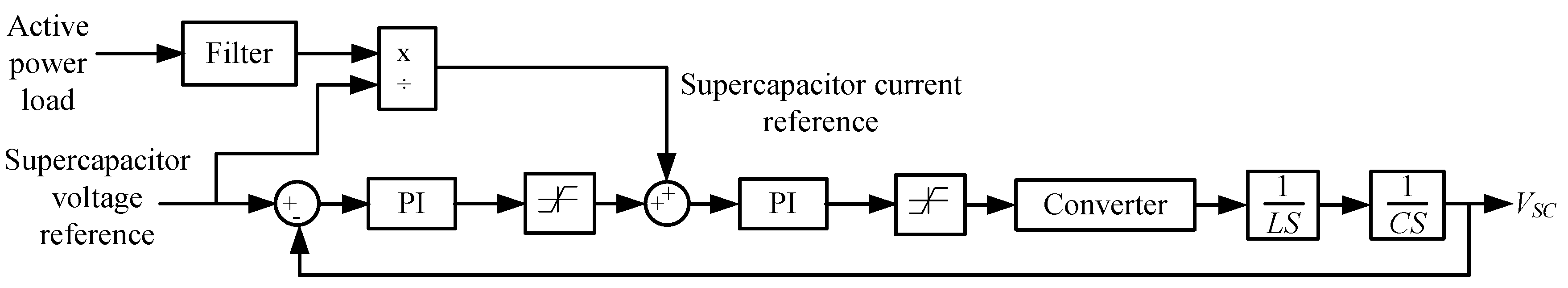
Supercapacitor-based hybrid converter with Proportional-Integral (PI) control [8]
-
Supercapacitor voltage fluctuation minimized
-
Simple modeling of converter system with conventional PI control for higher loading conditions
-
Effective control for heavy loading for up to 100% variation of peak load
-
Effectiveness in reducing power variation in light loading condition of lesser than 30% not proven
Battery Energy Storage System for frequency control using load frequency control dynamic simulator [37]
-
Different strategies for energy support used within the same control method depending upon the level of frequency deviation resulting in increased effectiveness for
-
Overcharging of battery observed leading to heating
-
Modeling of battery and generators as a single machine equivalent might have to be modified to represent hybrid propulsion ships
Battery and supercapacitor hybrid energy storage system with motor load following for torque and power fluctuation reduction [38]
-
Bus voltage information not required
-
Predictive load model developed from current motor load information
-
Applied to ship grid
-
Not effective for high frequency load changes such as in high sea states
Battery and supercapacitor hybrid energy storage system with bus voltage regulation for torque and power fluctuation reduction [38]
-
Low and high frequency load changes reduced
-
Motor load information not required
-
Simple voltage architecture without voltage measurement and feedback
-
Applied to ship grid
-
Sum of generator and hybrid energy storage system currents can lead to high currents for the system if they are of opposite directions
Battery and supercapacitor hybrid energy storage system with integrated energy management system for torque and power fluctuation reduction [38]
-
Optimization method minimizes DC bus variation, power tracking error and high battery current operation simultaneously
-
Generator found to provide almost constant power leading to high fuel consumption efficiency
-
Applied to ship grid
-
Full system information required including voltage measurements and motor loading conditions
Photovoltaic (PV)-Wind-Diesel battery hybrid system with PI and fuzzy logic control [9]
-
Fuzzy logic very effective in regulating both source and load variations for both voltage and frequency fluctuations
-
PI control used to generate synchronous reference frame signals for dq-axiscurrents would introduce delay to overall control strategy
Wind-Solar-Diesel hybrid energy storage system with PSO-based frequency controller [39]
-
PI controllers tuned by PSO reduced frequency deviations to a greater extent than classically tuned controllers
-
Online tuning of PI controllers has not been implemented for real time tuning of controllers
Active parallel hybrid energy storage system with Particle Swarm Optimization (PSO) control of battery and supercapacitor to decrease power fluctuations [40]
-
PSO method is very effective for non-linear optimization problem with multiple constraints on generator output power limits, generator ramp rate and energy storage capacity as well as its state of charge and current
-
Applied to Liquefied Natural Gas (LNG) ship grid
-
Real-time adjustment for output power fluctuation done
-
Motor braking energy is gainfully absorbed back to grid
-
Generator active power at time of motor starting has a spike of 50% despite energy storage action leaving room for improvement
Adaptive general predictive control used for supercapacitor energy storage system in multi-area network [41]
-
Frequency and tie power deviations reduced significantly by more than 80% and 60% using adaptive predictive control
-
Power handled by the supercapacitor energy storage system was 0.01 pu or lesser, thus, reducing heating effect and minimizing detrimental effects to lifespan of the system
-
Shipboard power systems might not be large enough to be multi-area networks
-
Load changes cases considered a maximum of 0.02 pu load addition which may not be applicable for application to seaborne vessels where the load changes are expected to be much higher at sea

