Structuring Surfaces by Microfinishing Using Defined Abrasive Belts

Institute of Machining Technology, Technical University Dortmund, 44227 Dortmund, Germany
*
Author to whom correspondence should be addressed.
Inventions 2017, 2(4), 33; https://doi.org/10.3390/inventions2040033
Submission received: 30 September 2017
/
Revised: 17 November 2017
/
Accepted: 27 November 2017
/
Published: 29 November 2017
Abstract
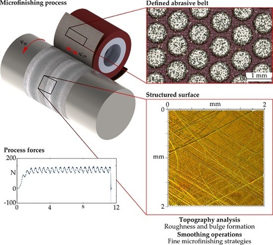
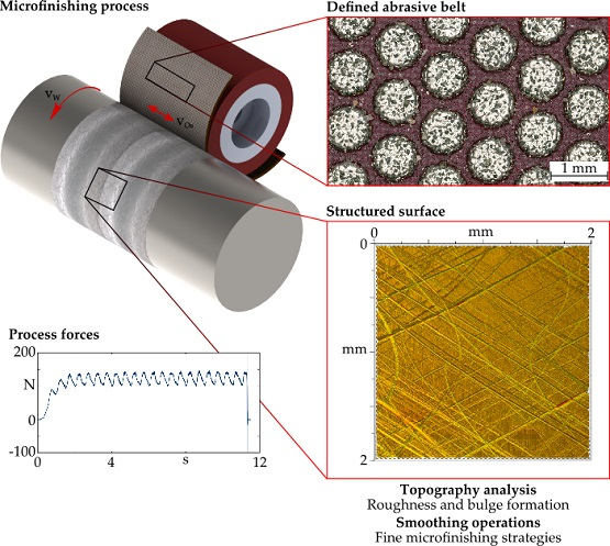
:Microfinishing, also known as superfinishing or short-stroke honing, is a commonly used process for generating technical surfaces focusing on tribological applications. Due to microfinishing processes high surface qualities are manufacturable regarding the surface roughness and bearing area ratio. While the required characteristics for tribological loaded workpieces are changing with their rising significance, the surface structuring is becoming more and more important. With the use of defined abrasive belts, the possibilities of surface structuring by microfinishing are enhanced. The possibilities and challenges concerning surface structuring by microfinishing applying defined abrasive belts are described in this research study. Therefore, a geometrical-kinematic simulation is used to predict the theoretical structures generated by microfinishing, while in experimental investigations the influences of kinematic parameters and a multi-stage process sequence are considered.
1. Introduction
The structure of surfaces influences their tribological behaviour significantly. Therefore, surface structuring is relevant for process engineering and the development of machining processes [1,2,3]. Honing processes, e.g., microfinishing, are often used to produce technical surfaces focusing their tribological functions [3,4,5,6,7]. As a last step in the process chain, microfinishing is mainly used to generate surfaces, which improves the tribological contact situation without changing deviations of the shape or geometry [8]. Microfinishing tools can be stones or flexible microfinishing belts or films. They are built out of bonding material and abrasive grains. When compared to grinding tools the grain types diamond, corundum, and silicium-oxide are the same, whereas the grain size is typically smaller [3,4,6]. Usually, microfinishing films have a maximum grain size of dK = 125 µm, whereas the minimum grain size is dK ≤ 1 µm [5,6,7,8].
Because microfinishing is a type of honing process, the general kinematics are similar. The microfinishing process is characterised by a rotation of the workpiece and a superimposed orthogonal oscillation of the tool. The oscillation in a microfinishing process has a frequency of up to fOs = 21 Hz, and a maximum amplitude up to A = 3 mm [8]. This is equivalent to a width of oscillation of lOs = 6 mm. Due to this short stroke width, microfinishing is also called short-stroke honing.
By the implementation of several microfinishing steps with subsequently decreasing grain size, the typical microfinished surfaces can be produced. Regarding these several microfinishing steps different characteristics of the surface are generated. During the first operation, the rough microfinishing profile peaks and valleys are generated. In the course of the following steps, profile peaks should be removed. These fine finishing steps cause the typical plateau-structure, hence the resulting high bearing area ratio. The remaining surface is typically characterised by homogenous valleys in cross-grid pattern and flat areas or plateaus without profile peaks [6,7,8,9]. The tool and the process parameters, causing different material removal mechanisms, influence the resulting surface characteristics roughness and bearing area ratio [6,7,10,11]. When considering previous models the material removal mechanisms in microfinishing processes can be assumed as an interaction of the tribological wear mechanisms microcracking, microfatigue, and the mechanisms microridging, microploughing, and microcutting in analogy to longitudinal stroke honing processes [5,12,13,14,15].
Recent studies show the high potential of a milled and microfinished surface in tribological applications. For example, better results concerning wear compared to ground or polished surfaces are presented by a milled and microfinished surface in the case of reciprocating sliding contact [6,7]. Based on this it has to be analysed in which way it is possible to produce suitable surface structures by applying a microfinishing process. In this case, defined abrasive belts with defined spots were used in order to combine the advantages of microfinishing processes with the use of deterministic tools in order to generate certain structured surfaces. These investigations are focused on the possibilities for surface structuring by means of microfinishing, in order to obtain basic knowledge about the interactions of the parameters using defined abrasive belts. Other studies regarding defined abrasive belts focus on tool wear and address belts with pyramidal agglomerates [10,16].
2. Materials and Methods
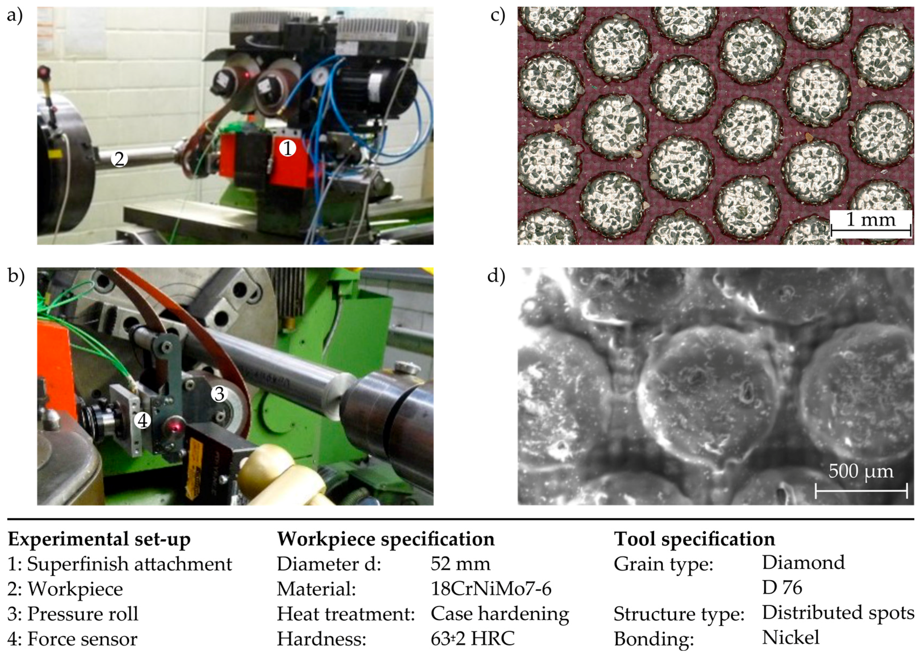
The investigations were carried out on a turning machine, using an additional system for force-controlled microfinishing, applying a defined pressure. The workpiece material was 18CrNiMo 7-6, a case hardening steel. The cylindrical workpieces with a diameter of d = 52 mm were prepared using an inductive heat treatment resulting in a hardness up to 63 ± 2 HRC. The experimental set-up is shown in Figure 1a,b. The force-controlled plunge microfinishing process was conducted using a defined abrasive belt, compare Figure 1c,d. The microfinishing belt that was used for the structuring experiments consists of a basic layer of polyester fabric and of several nickel-based spots with diamond grains. The distance between these spots is regular, so that the microfinishing belt has a defined structure. The diamond abrasive grains have a grit size of D 76.
The lateral distances and geometrical information about the structured belt were used to generate a model of the tool for the geometrical-kinematic simulation. A laser, a piezo-electrical dynamometer, and a light scanning system were used to record the rotational speed, the process forces, and the oscillation velocity. The measured oscillation velocity was used for the simulation later on. Moreover, the force measurement was used to control the cutting time tc of the microfinishing process by monitoring the applied normal force. When it reached a set threshold, a countdown started and the process was stopped after a defined cutting time. Hence, it is possible to control the cutting time, and thus the length of overlap between workpiece and tool. Caused by the force-controlled process, the tool and workpiece are in contact before the stationary normal force is reached. Thus, the parameter of cutting time, tc, is further used as the process duration value.
3. Results
3.1. Tool Modelling and Simulation
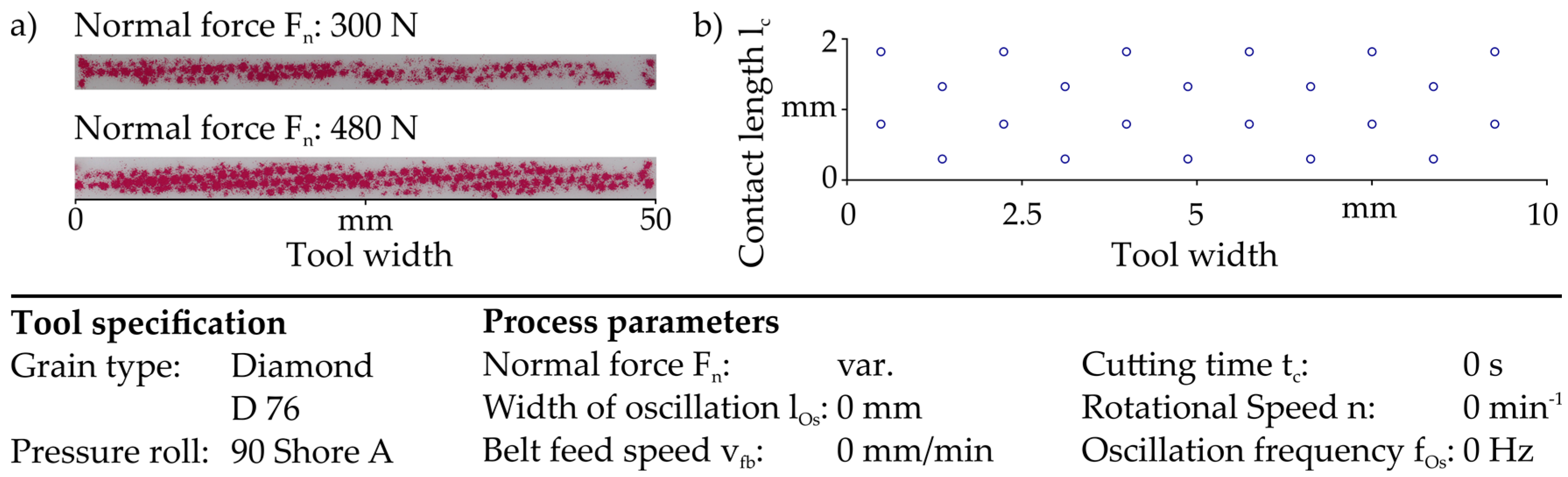
As mentioned above, the tool structure was modelled for a geometrical-kinematic simulation based on measuring data. Therefore, the contact conditions between tool and workpiece were measured by using pressure measurement films for varying contact pressures. Figure 2 shows an example of these measurements (a) and a section of the modelled tool (b).
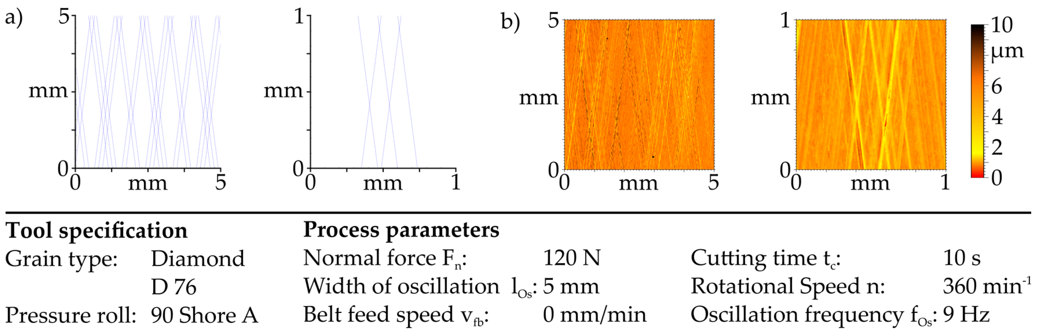
Based on the measuring data the contact length for the modelled tool is defined for the simulation regarding different adjusted forces. In addition, the oscillation frequency and rotational speed are used as input parameters for the simulation. Due to the velocities of the microfinishing process, the grains are moved in x- and y-direction creating lines along their paths regarding their relative movements. The geometrical-kinematic simulation shows the resulting contact track of each grain-spot over the workpiece. Because it is a pure geometrical-kinematic simulation, different material removal mechanisms that are caused by material characteristics, cutting speeds, or grain forms are not taken into account. Thus, the simulated structure is a theoretical image of the relative movement between the spots and the workpiece. Figure 3a shows the resulting paths for the chosen parameters. Each spot creates a thin line that describes the honing grooves. In comparison, Figure 3b depicts the experimentally generated structure for the same parameters.
With reference to the varying grain distribution and the different grain forms, the resulting structures can differ. The experiments show that one spot is able to produce more than only one honing groove caused by the variety of existing grains per spot. Moreover, deviations of the kinematic parameters that are caused by the dynamic behaviour of the machine tool can lead to an offset between theoretically simulated and experimentally produced structures.
The simulated structures look similar to the microfinished surface structures, compare Figure 3a,b. Nevertheless, the depth and width of cutting grooves are not considered in the geometrical-kinematic simulation, because they are mainly influenced by the specific material removal mechanisms taking place in microfinishing.
The geometrical-kinematic simulation was mainly used to generate structures virtually that can be produced by the usage of the defined abrasive belt and to understand the geometrical-kinematic interactions between the different velocities during microfinishing. The results were used as a basis for the following experimental investigations. Based on different simulated structures, experiments focussing the force analysis and the possibilities of smoothing the surface by subsequent microfinishing operations were carried out.
3.2. Force Analysis Regarding Cutting Speed
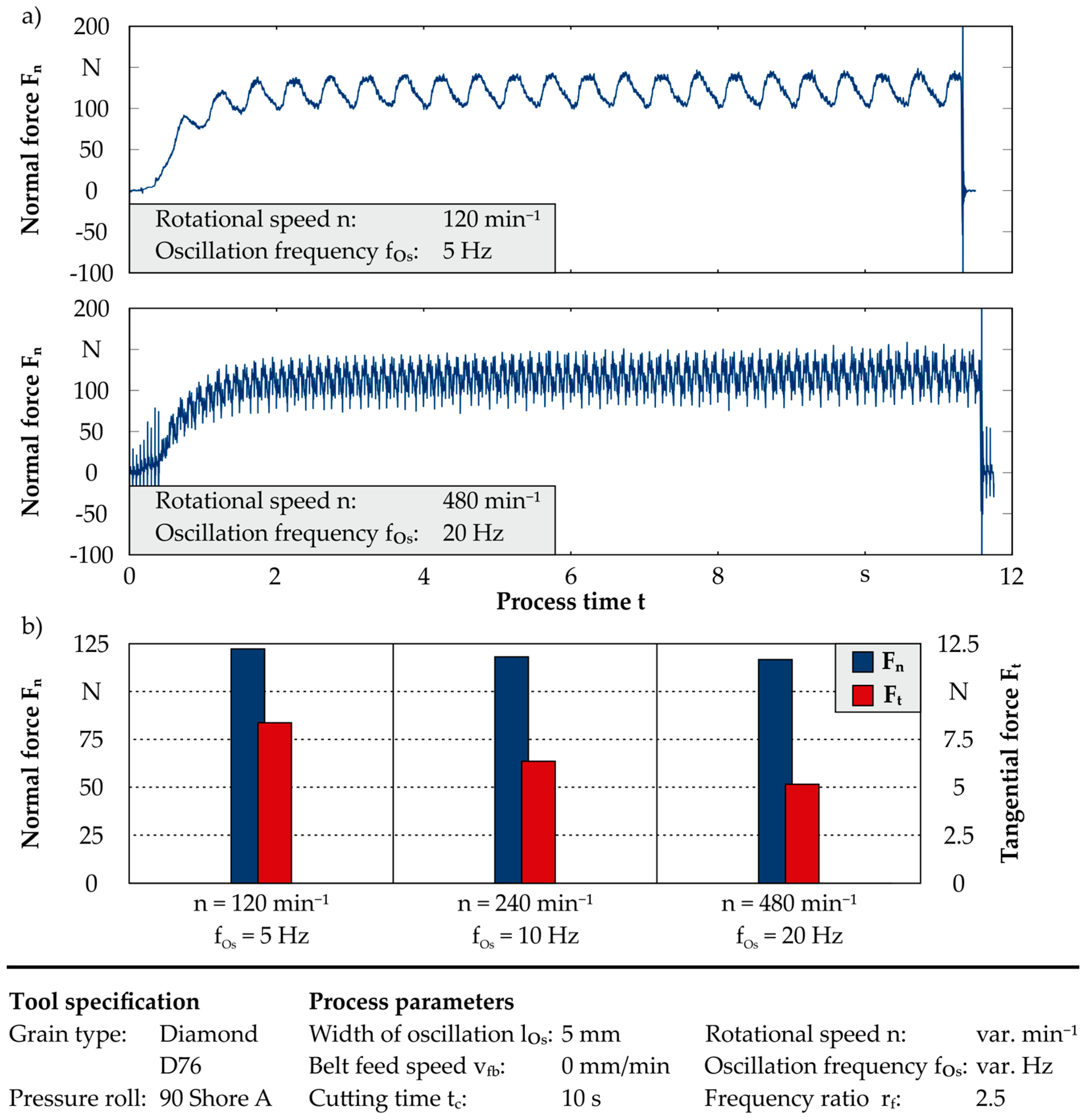
Using microfinishing processes with a belt feed speed of vfb = 0 mm/min, the same surface structure can be generated by varying the process parameters. The ratio between the rotational speed and the oscillation frequency can be kept constant, raising both frequencies in the same relation, which results in an increasing cutting speed. Therefore, the following section discusses three different chosen combinations of rotational speed and oscillation frequency. In order to generate a more detailed understanding of the microfinishing process, an analysis of the resulting process force and their components was conducted. Thus, the normal force Fn, corresponding with the force resulting from the applied pressure, as well as the tangential force Ft were analysed. Moreover, the force component in axial direction of the workpiece Fa corresponding to the direction of the oscillation of the tool was recorded as well. In Figure 4a, the normal forces over the process time are shown for a ratio of rf = 2.5 using two different process parameter combinations. Furthermore, the mean values of the normal force and the tangential force are given as well. In order to avoid influences of the run-in and run-out characteristics of the process the mean values were determined in a stationary phase of the microfinishing process within a process time of ∆t = 8 s.
At the beginning of the process, the normal force increases due to the applied pressure until a stationary phase of the microfinishing process is reached. The two different force paths, which are shown in Figure 4a), directly reveal the influence of the chosen oscillation frequency on the normal force. For a rotational speed of n = 480 min−1 and a frequency of fOs = 20 Hz, this influence becomes obvious by force peaks, which superimpose the signal of the normal force. For a rotational speed of 120 min−1 and an oscillation frequency of 5 Hz the impact is not that pronounced. Hence, there is a strong influence on the process and system by an increasing oscillation frequency, which might affect the surface topography as well. Analysing the mean values of the normal and tangential force, the normal force is at a comparable level for all three of the cutting speeds. That corresponds with the constant set pressure and therefore assumed steady normal force. By contrast, there is a decrease in the tangential force with an increasing cutting speed, which might occur due to different material cutting mechanisms.
3.3. Microfinishing Process Sequence—Structuring and Smoothing
Due to the lateral bulge formation along the honing grooves high surface peaks exist on the honing plateau of the structured surfaces. This leads to a high running-in wear in tribological applications. Therefore, it is useful to implement a second microfinishing operation in order to smooth the surface by removing the lateral bulges. Thus, it is challenging to maintain the initial surface structure regarding the grooves and the plateaus by removing the lateral bulges only. The following paragraph analyses the different strategies for smoothing the structured surface.
3.3.1. Initial Surface
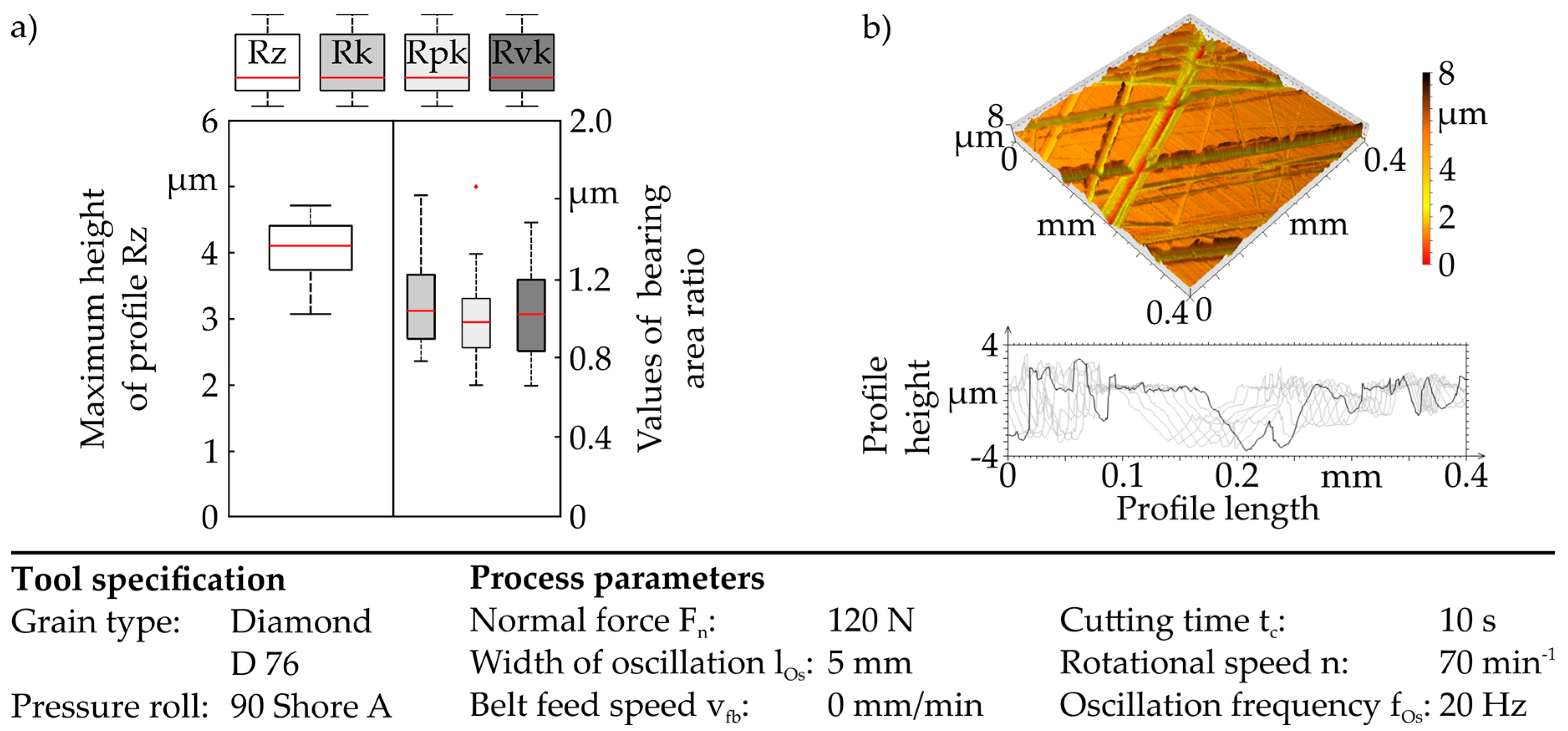
With regard to the comparability of the varying strategies for the subsequent microfinishing operation, the initial surface is kept constant by using the same structuring parameters. The initial surface is shown in Figure 5a, with the maximum height of profile (Rz) and the values of bearing area ratio, core roughness depth (Rk), reduced peak height (Rpk), and reduced valley depths (Rvk). Based on the box plot evaluation red dots are outliers while the red lines represent the median of the multiple measurements. The topography of the structured surface and a profile series are shown in Figure 5b.
The lateral bulging besides the honing grooves is clearly observable in the profile series in Figure 5b. Microploughing and microridging affect these lateral bulges. But they do not appear constantly caused by the process sequence characterised by a multi contact of every workpiece area and tool. This leads to removal of lateral bulges with an increasing process time. Due to the offset of the structure regarding an increasing process time it is not capable to reduce lateral bulge formation by longer process durations. On the one hand, existing bulges are removed within further contacts between tool and these bulges, on the other hand, new bulges are generated in the same time. Furthermore, the influence of tool wear on the resulting structure is previously unknown. With regard to the values of bearing area ratio it is apparent that all of the parameters are close together. In this case the height of bulges, characterised by the reduced peak height (Rpk) and the depth of the grooves, described by the reduced valley depth (Rvk), are comparable. This corresponds to the effect shown in the profile series.
3.3.2. Subsequent Microfinishing Operation—30 µm Film
In order to reduce the influence on the initial surface structure, a strategy without oscillation was conducted in addition to an oscillation frequency of fOs = 21 Hz. Moreover, the microfinishing tools were varied. Microfinishing films with grain sizes of dK = 30 µm and dK = 9 µm were used to achieve a removal of the lateral bulges without a secondary surface structuring. Besides the factors oscillation frequency and tool variation, the process time was varied stepwise.
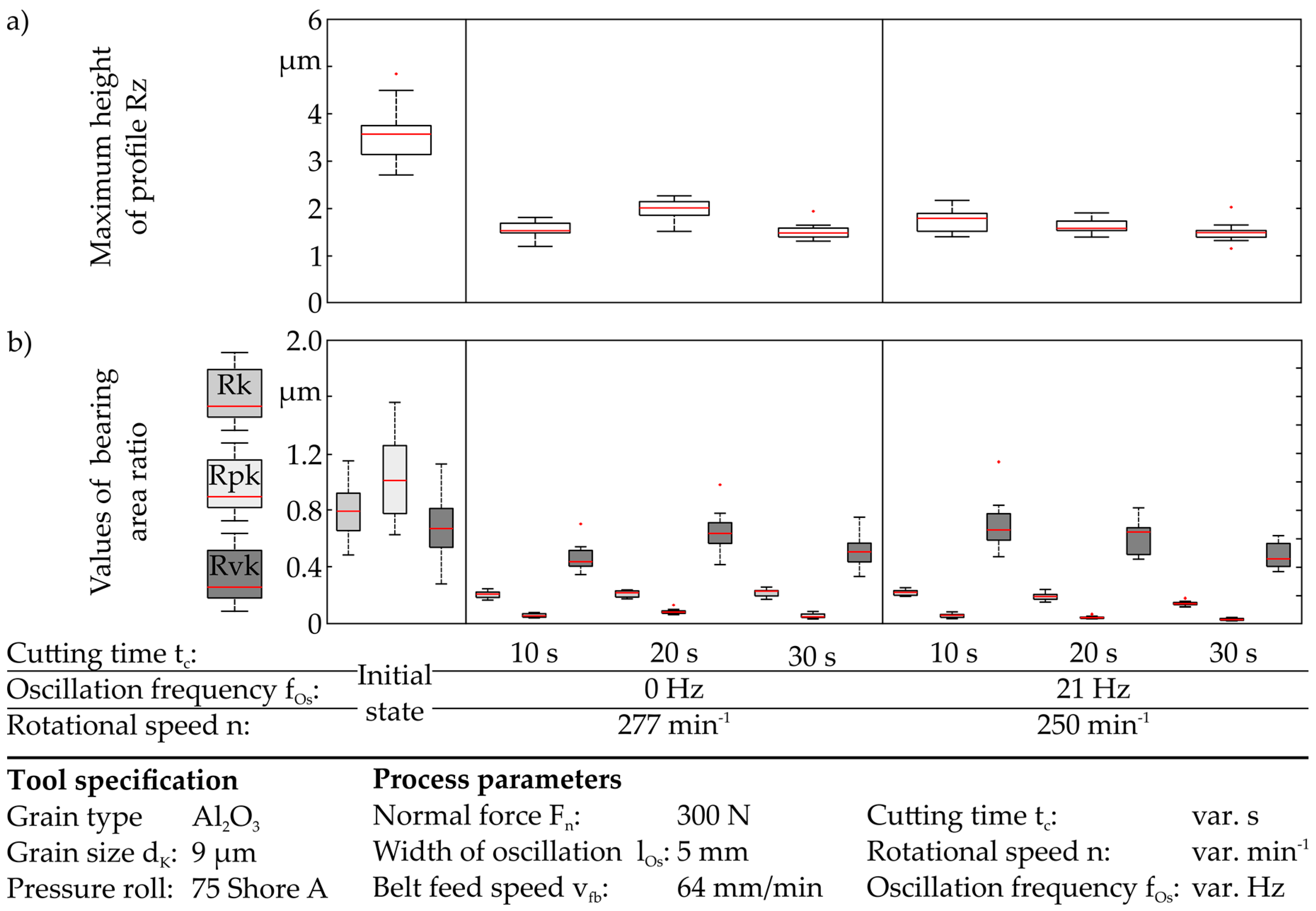
For the following smoothing operation, a microfinishing film with aluminium oxide grains (Al2O3, dK = 30 µm), and a randomized grain distribution was used. Figure 6 shows the diagrams of Rz and the values of the bearing area ratio for the smoothing operation with and without oscillation. For each process, the cutting speed resulting from the components of the rotational speed n and the oscillation frequency fOs are kept constant. Hence, the rotational speed is reduced to n = 250 min−1 for an oscillation of fOs = 21 Hz.
When considering the Rz values, it is noticeable that a reduction occurs in each case independent of the varied parameters. With increasing cutting time, the values are reduced. When comparing the processes with and without oscillation, the reduction of the Rz values is similar for a cutting time of tc = 10 s. Regarding longer cutting times, the influence of the oscillation frequency is significant as the Rz values are reduced continuously. For fOs = 21 Hz and a cutting time of tc = 30 s the Rz is reduced to less than 1 µm, whereas in the case of microfinishing without oscillation further surface smoothing is neglectable.
Focusing the values of bearing area ratio, it is obvious that the surface is smoothed by decreasing reduced peak heights Rpk for all of the experiments. The increasing cutting time leads to a reduction of the core roughness depth Rk as well. Regarding the reduced valley depths, the reduction does not differ for the varying cutting times without an oscillation. When considering the experiments with an oscillation frequency of fOs = 21 Hz, it is apparent that the reduction of all of the values is stronger for each cutting time. Applying a cutting time of tc ≥ 20 s, the surface shows a plateau structure characterised by a Rvk value that is higher than the Rk and very small Rpk values. Generally, the process with oscillation produces an increasing material removal in comparison to the process without oscillation with the same cutting speed. It can be concluded that the tool oscillation affects the material removal mechanisms significantly, so that the material removal rate increases. Due to this high material removal, the initial surface is changed too much and especially by using high cutting times new grooves occur on the surface for both process strategies. As mentioned before, the challenge in smoothing operations with microfinishing is to avoid those effects. Therefore, another microfinishing tool was used regarding its suitability for smoothing the initial structure.
3.3.3. Subsequent Microfinishing Operation—9 µm Film
The used microfinishing film consists of randomly distributed aluminium oxide grains with a size of dK = 9 µm. Figure 7 shows the diagrams of the maximum profile height and the values of bearing area ratio.
In comparison to the initial state the maximum height of profile Rz is reduced to its half, so it is Rz = 1.2–2.0 µm. The oscillation and longer cutting times result in a smaller scattering of the measurements. In general, a reduction of the Rz can be seen with increasing cutting times for both of the strategies. The values of bearing area ratio are similar. On the one hand, there are no significant differences between the strategies; on the other hand, the values are reduced by longer cutting times. For both strategies, a plateau like surface already occurs after 10 s of cutting time based on the ratio between Rk, Rpk and Rvk.
Through comparing the different microfinishing tools for smoothing, it can be found that the material removal ratio is still higher for a larger grain size concerning the Rz values. For the usage of a 30 µm finishing film, the Rz is reduced to a minimum of less than 1.0 µm, while the 9 µm film only results in a reduction to 1.5 µm applying the same parameters. Concerning the values of bearing area ratio, this is comparable. The reduced valley depth is not reduced by use of the finishing film with dK = 9 µm. Based on this effect it can be concluded that the level of plateaus between the microfinishing grooves is close to the initial state, therefore the depth of the grooves is the same, whereas the bulges are removed.
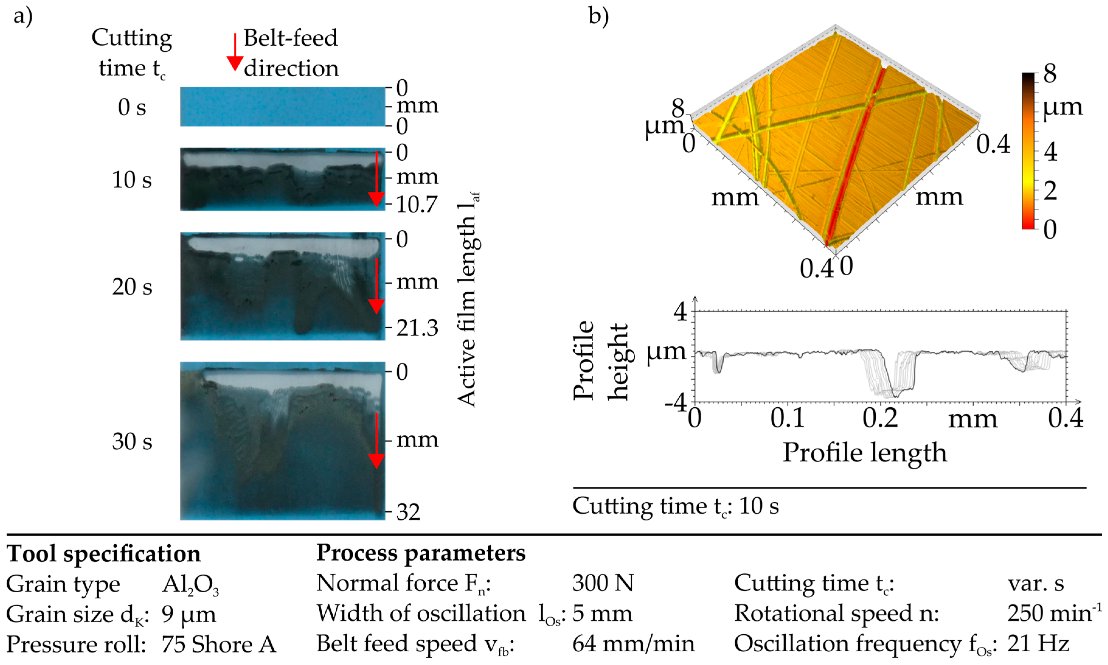
Additionally, a very high initial tool wear is observed. Figure 8a depicts the tool wear for the finishing film that is used in a process with an oscillation. Besides, Figure 8b shows the surface topography in a three dimensional view and a profile series for the cutting time of tc = 10 s.
In the first contact section, the upper area of the finishing film is worn by abrasive wear. This leads to a removal of the abrasive grains and the bonding, so that only the transparent basic layer is remaining. Regarding the constant belt feed speed, this area can be matched to the first three seconds of the process. With rising process time, the wear mechanism changes from abrasive wear to adhesive wear, decreasing with higher cutting time.
Due to the high bulges and the high surface roughness the fine microfinishing film with a grain size of dK = 9 µm is overloaded within the first three seconds of the process. Nevertheless, the contact and the relative movements between tool and workpiece lead to an abrasive wear of the tool on the one hand. On the other hand, the surface of the workpiece is smoothed by cutting the bulges as well. This effect coincides with the conclusion of wear mechanisms acting as material removal mechanisms in this microfinishing process. Surface smoothing by abrasion or cutting of the bulges and decreasing tool wear are superimposed.
Using the 9 µm-microfinishing film, a small material removal rate is guaranteed even after the initial tool wear. The tool wear results in a lower material removal. This leads to the opportunity of smoothing the surface without generating new grooves. The result, a plateau surface topography without any bulges with the initial structure remaining, as shown in Figure 8b.
4. Discussion
Generally, the results with a defined abrasive belt can be an opportunity to generate structured surfaces even if the process forecasting is still not as detailed as the resulting structure. Beneath the used tool there are a lot of other defined microfinishing belts available, and in combination with the process parameters a large number of different structures can be created.
Regarding these findings, some challenges occur when structuring surfaces with defined microfinishing belts, which are discussed in the following subchapters.
4.1. Tool Model and Geometrical-Kinematic Simulation
The machined and the simulated surface differ in the number of grooves, because the modelled tool is simplified using the spots as contact points for the presented geometrical-kinematic simulation. Whereas, the tool model assumes only one grain per spot, several grains are located to the respective spot in fact.
In addition, the dynamic behaviour of the machine, e.g., deviations in rotational speed, influences the reliability of structuring with microfinishing processes and leads to an offset of the structure in comparison to the simulated structure. The resulting offset is influenced by the process time, as well. This should be considered in the process design. Furthermore, these aspects like machine tool influence and grain distribution have to be analysed and should be implemented in the simulation to get a more detailed forecasting of the resulting structure. Therefore, a more detailed tool model is considered as expedient, taking the grain distribution and single grain forms and orientation into account. It could be used to expand the simulation from geometrical-kinematical to a geometrical-physical-based simulation that also considers the material removal mechanisms.
4.2. Cutting Speed Influences on the Process Forces
The force measurements show that the cutting speed mainly influences the tangential force even if this force component is relatively small as compared with the normal force. It is evident that higher cutting speeds result in a reduction of tangential force. This effect might be explained by changing material removal mechanisms with different cutting speeds. Given the fact that rotational speed and oscillation frequency are changed in the same relation, it is not comparable which component of the resulting cutting speed has the main influence in this context. For this purpose, further experimental investigations regarding the parameter influences on the affecting forces have to be conducted for defined microfinishing belts and common microfinishing films. Moreover, force analysis can be used to develop a better fundamental understanding of the interaction between the material removal mechanisms and especially of the occurring tool wear for defined abrasive belts.
4.3. Subsequent Microfinishing—Surface Smoothing
Due to the lateral bulge formations during the single grain engagement, the structured surfaces are not suitable for tribological contacts. Hence, a subsequent machining operation is necessary. The findings show that microfinishing using microfinishing film is capable when using the optimal process strategy and tool specification. For larger grain sizes, it is more challenging to handle the process by focussing the material removal without removing the initial structure plateaus and grooves because of the higher material removal rate. The grains should not overcome the contact of grain and bulges so that the grains are in contact with plateaus from the beginning of the process time, where they influence the initial structure.
Using an aluminium oxide grain with a size of dK = 9 µm, the task of smoothing the structured surface can be solved by removing bulges without removing the plateau material. Therefore, based on the measured data and the tool wear investigations further interpretations of the material removal mechanisms can be concluded. Although the grains and the bonding are completely removed from the finishing film, the bulges are also removed. In these first seconds of process, it is not conceivable that the common material removal mechanisms microridging, microploughing, and microcutting are acting. It is rather assumed that the contact conditions are similar to slide contacts in slide-friction loading that leads to the removal of the bulges while the plateau-level has less contact with the tool. Concluding, with the grain size of dK = 9 µm a low material removal rate is guaranteed, even if the initial tool wear is overcoming. The small material removal rate and the lower appearance of the material removal mechanisms microploughing, microridging, and microcutting lead to the opportunity of smoothing the surface without generating new grooves.
Further findings can be focused on these effects by analysing shorter process sequences and using other grain sizes. An analysis of the process forces can also be consulted. This can help to differentiate between material removals mechanisms in more detail so that the interactions of the process parameters can be controlled more precisely.
Acknowledgments
The scientific results presented in this manuscript are based on the research project “Increasing Power Density and Durability of Highly Stressed Slide Faces by an Improved Surface Integrity Generated with Adapted Machining Processes”, which was funded by the Mercator Research Center Ruhr, Essen, Germany (Project: MERCUR PR-2011-0002).
Author Contributions
Meik Tilger, Tountzer Tsagkir Dereli and Dirk Biermann conceived and designed the experiments; Sebastian Schumann programmed the geometrical-kinematic simulation; Tountzer Tsagkir Dereli performed the experiments and worked with the simulation; Monika Kipp, Meik Tilger, Sebastian Schumann and Tountzer Tsagkir Dereli analysed the data; all Authors discussed the results and wrote the paper.
Conflicts of Interest
The authors declare no conflict of interest.
Abbreviations
| Abbreviation | Meaning | Unit |
| A | Amplitude | mm |
| Al2O3 | Aluminium oxide | - |
| d | diameter | mm |
| dk | Grain size | µm |
| Fn | Normal force | N |
| Ft | Tangential Force | N |
| fOs | Oscillation frequency | Hz |
| HRC | Rockwell hardness | - |
| lc | Contact length between tool and workpiece | mm |
| lOs | Width of oscillation | mm |
| n | Rotational speed | min−1 |
| rf | Ratio fOs/n | - |
| Rk | Core roughness depth | µm |
| Rpk | Reduced peak height | µm |
| Rvk | Reduced valley depth | µm |
| Rz | Maximum profile height | µm |
| SEM | Scanning electron microscope | - |
| t | Process time | s |
| tc | Cutting time | s |
| vfb | Belt feed speed | mm/min |
References
- Tillmann, W.; Leif, H.; Stangier, D.; Laemmerhirt, I.-A.; Biermann, D.; Kersting, P.; Krebs, E. Wear behavior of bio-inspired and technologically structured HVOF sprayed NiCrBSiFe coatings. Abbr. Coat. Technol. 2015, 280, 16–26. [Google Scholar] [CrossRef]
- Bruzzone, A.A.G.; Costa, H.L.; Lonardo, P.M.; Lucca, D.A. Advances in engineered surfaces for functional performance. CIRP Ann. 2008, 57, 750–769. [Google Scholar] [CrossRef]
- Mang, T.; Bobzin, K.; Bartels, T. Industrial Tribology, 1st ed.; Wiley: Aachen, Germany, 2011; pp. 1–21, 113–136. ISBN 978-3-527-320578. [Google Scholar]
- Paffrath, K.-U. Untersuchungen zum Kraftgeregelten Langhubhonen auf Multifunktionalen Bearbeitungszentren. Ph.D. Thesis, Technical University Dortmund, Dortmund, Germany, 2011. [Google Scholar]
- Hashimoto, F.; Yamaguchi, H.; Krajnik, P.; Wegener, K.; Chaudhari, R.; Hoffmeister, H.-W.; Kuster, F. Abrasive fine-finishing technology. CIRP Ann. 2016, 65, 597–620. [Google Scholar] [CrossRef]
- Goeke, S. Oberflächenstrukturierung tribologisch beanspruchter Funktionsflächen durch Microfinishen. Ph.D. Thesis, Technical University Dortmund, Dortmund, Germany, 2016. [Google Scholar]
- Goeke, S.; Biermann, D.; Stickel, D.; Stemmer, P.; Fischer, A.; Geenen, K.; Huth, S.; Theisen, W. Enhancing the Surface Integrity of Tribologically Stressed Contacting Surfaces by an Adjusted Surface Topography. Proced. CIRP 2014, 13, 214–218. [Google Scholar] [CrossRef]
- Schibisch, D.M.; Friedrich, U. Superfinish-Technologie, 3rd ed.; Verlag Moderne Industrie: Landsberg, Germany, 2011; pp. 1–70. ISBN 978-3-86236-016-1. [Google Scholar]
- Biermann, D.; Abrahams, H.; Goeke, S. Optimization of guide pads for the BTA deep hole drilling of high alloyed steels by microfinishing. Prod. Eng. 2014, 8, 33–40. [Google Scholar] [CrossRef]
- Serpin, K.; Mezghani, S.; El Mansori, M. Wear study of structured coated belts in advanced abrasive belt finishing. Surf. Coat. Technol. 2015, 284, 365–376. [Google Scholar] [CrossRef]
- Khellouki, A.; Rech, J.; Zahouani, H. Micro-scale investigation on belt finishing cutting mechanisms by scratch tests. Wear 2013, 308, 17–28. [Google Scholar] [CrossRef]
- Martin, K.; Yegenoglu, K. HSG-Technologie, 1st ed.; Firma Guehring Automation GmbH: Stetten a.k.M.-Frohnstetten, Germany, 1992; pp. 14–39. [Google Scholar]
- Tilger, M.; Siebrecht, T.; Biermann, D. Fundamental Investigations of Honing Processes Related to the Material Removal Mechanisms. In Proceedings of the 7. WGP-Jahreskongress, Aachen, Germany, 5–6 October 2017; pp. 121–128, ISBN 978-3-86359-555-5. [Google Scholar]
- Zum Gahr, K.-H. Wear by hard particles. Tribol. Int. 1998, 31, 587–596. [Google Scholar] [CrossRef]
- Martin, K. Der Werkstoffabtragvorgang beim Feinbearbeitungsverfahren Honen. Maschinenmarkt 1976, 60, 1074–1078. [Google Scholar]
- Serpin, K.; Mezghani, S.; El Mansori, M. Multiscale assessment of structured coated abrasive grits in belt finishing process. Wear 2015, 332–333, 780–787. [Google Scholar] [CrossRef]
Figure 1.
Process periphery. (a,b) Experimental set-up; defined abrasive belt; (c) microscopic image; (d) SEM-image.
Figure 1.
Process periphery. (a,b) Experimental set-up; defined abrasive belt; (c) microscopic image; (d) SEM-image.

Figure 2.
Contact conditions. (a) Static contact measurement; (b) modelled tool.

Figure 3.
Verification of the simulation. (a) Simulated structure; (b) microfinished structure.

Figure 4.
Force analysis for varying cuttings speed. (a) Force paths of the normal force Fn; (b) Mean values of the normal force Fn and the tangential force Ft.
Figure 4.
Force analysis for varying cuttings speed. (a) Force paths of the normal force Fn; (b) Mean values of the normal force Fn and the tangential force Ft.

Figure 5.
Initial surface structure. (a) Roughness parameters; (b) surface topography and profile serie.
Figure 5.
Initial surface structure. (a) Roughness parameters; (b) surface topography and profile serie.

Figure 6.
Surface parameters of the initially structured surface and the subsequently microfinished surface using the grain size dK = 30 µm. (a) Rz; (b) Rk, Rpk and Rvk.
Figure 6.
Surface parameters of the initially structured surface and the subsequently microfinished surface using the grain size dK = 30 µm. (a) Rz; (b) Rk, Rpk and Rvk.
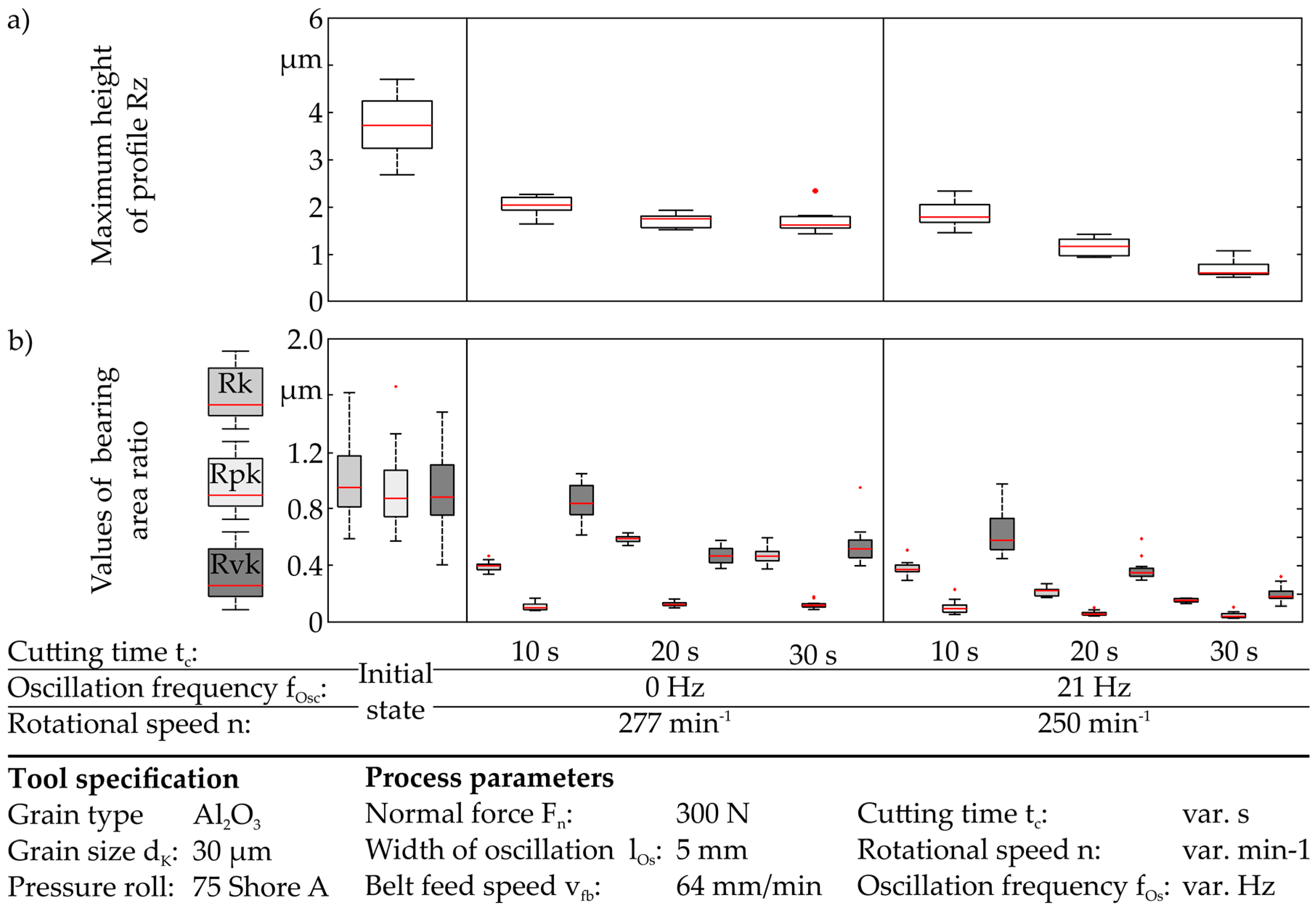
Figure 7.
Surface parameters of the initially structured surface and the subsequently microfinished surface using the grain size dK = 9 µm. (a) Rz; (b) Rk, Rpk, and Rvk.
Figure 7.
Surface parameters of the initially structured surface and the subsequently microfinished surface using the grain size dK = 9 µm. (a) Rz; (b) Rk, Rpk, and Rvk.

Figure 8.
Subsequent microfinishing using a film with a grain size of dK = 9 µm. (a) Tool wear; (b) surface topography and profile series.
Figure 8.
Subsequent microfinishing using a film with a grain size of dK = 9 µm. (a) Tool wear; (b) surface topography and profile series.
© 2017 by the authors. Licensee MDPI, Basel, Switzerland. This article is an open access article distributed under the terms and conditions of the Creative Commons Attribution (CC BY) license (http://creativecommons.org/licenses/by/4.0/).
Share and Cite
MDPI and ACS Style
Tilger, M.; Kipp, M.; Schumann, S.; Dereli, T.T.; Biermann, D. Structuring Surfaces by Microfinishing Using Defined Abrasive Belts. Inventions 2017, 2, 33. https://doi.org/10.3390/inventions2040033
AMA Style
Tilger M, Kipp M, Schumann S, Dereli TT, Biermann D. Structuring Surfaces by Microfinishing Using Defined Abrasive Belts. Inventions. 2017; 2(4):33. https://doi.org/10.3390/inventions2040033
Chicago/Turabian StyleTilger, Meik, Monika Kipp, Sebastian Schumann, Tountzer Tsagkir Dereli, and Dirk Biermann. 2017. "Structuring Surfaces by Microfinishing Using Defined Abrasive Belts" Inventions 2, no. 4: 33. https://doi.org/10.3390/inventions2040033