Contact-Free Support Structures for Part Overhangs in Powder-Bed Metal Additive Manufacturing

1
Additive Manufacturing Laboratory, Marshall Space Flight Center, Huntsville, AL 35812, USA
2
Department of Mechanical Engineering, University of Alabama, Tuscaloosa, AL 35487, USA
*
Author to whom correspondence should be addressed.
†
Current address: Department of Industrial Engineering, University of Louisville, Louisville, KY 40292, USA.
Inventions 2018, 3(1), 2; https://doi.org/10.3390/inventions3010002
Submission received: 27 November 2017
/
Revised: 24 December 2017
/
Accepted: 26 December 2017
/
Published: 28 December 2017
(This article belongs to the Special Issue Innovations in 3-D Printing)
Abstract
:This study investigates the feasibility of a novel concept, contact-free support structures, for part overhangs in powder-bed metal additive manufacturing. The intent is to develop alternative support designs that require no or little post-processing, and yet, maintain effectiveness in minimizing overhang distortions. The idea is to build, simultaneously during part fabrications, a heat sink (called “heat support”), underneath an overhang to alter adverse thermal behaviors. Thermomechanical modeling and simulations using finite element analysis were applied to numerically research the heat support effect on overhang distortions. Experimentally, a powder-bed electron beam additive manufacturing system was utilized to fabricate heat support designs and examine their functions. The results prove the concept and demonstrate the effectiveness of contact-free heat supports. Moreover, the method was tested with different heat support parameters and applied to various overhang geometries. It is concluded that the heat support proposed has the potential to be implemented in industrial applications.
1. Introduction
Metal additive manufacturing (AM) continues to evolve as an innovative technology that stimulates design freedom, improves part functionality, and increases production agility for complex parts that are costly to make using conventional manufacturing processes. Currently, metal AM processes based on selective melting of a specified surface area in a powder bed have emerged as a key technology, termed “powder bed fusion” (PBF) process per ASTM standard [1], with potential of full-scale production. During the process, a focused energy beam, either electron or laser, (thus, called electron beam additive manufacturing (EBAM) or selective laser melting (SLM), respectively), is applied to heat and melt metal particles and transform to a solid subject by self-cooling solidification. Recently, there have been many modeling studies for metal AM or similar processes to address different subjects, including process characteristics, e.g., [2], and part geometry, e.g., [3,4]. One of the challenges in AM part designs is overhangs or similar down-facing features, which require structures to support the weight of an overhang. For PBF metal AM processes such as EBAM, support structures for an overhang are not intuitively needed, because the powder bed self-sustains the weight of the built overhang. However, overhang or down-facing features in PBF metal AM tend to exhibit distortions in geometry such as warping. It is known that metal PBF AM parts are susceptible to distortions because of the temperature induced deformation mechanism [5]. Further, in fabricating features like overhangs, warping occurs, due to non-uniform thermal stresses and the lack of mechanical constraints to the overhang. In practice, to overcome overhang distortion problems, support structures still have to be incorporated, serving as geometric constraints, to prevent overhang distortions. Typical support structures are thin plates with limited contact (tooth type) with an overhang. Such a method, mostly empirical, can eliminate or largely reduce the overhang distortions. However, the post-process to remove support structures is rather tedious. Figure 1 below shows an example of overhang warping if no support structures and mitigation using conventional support structures.
Geometric defects associated with part overhangs and the need of support structures have received increased attention from the AM community, though there are few reports for metal AM in literature. Recently, Vora et al. attempted to benchmark the problems with overhangs in powder-bed metal AM and reported cases where overhang warpage occurs [6]. There are also a few studies reporting support structures in SLM. However, they mostly focused on “lattice” type structures for material usage and post-processing minimization [7,8,9,10,11]. For example, Yan et al. studied “cellular lattice structure” for support and investigated the cellular geometry parameters to minimize the materials needed for support [7]. Further, Jihabvala et al. reported using pulse laser, instead of continuous, to fabricate support structures which may be much easier to be removed [8]. Strano et al. [11] also developed cellular supports for overhang parts. The periodic implicit surface functions were used to generate different cellular sizes and shapes of lattice supports in a computer-aided design (CAD) file. The authors claimed that the implicit function approach for cellular support designs is found to be versatile, because it allows geometries to be simply defined by mathematical expressions.
On the other hand, Calignano [12] investigated different types of support structures: a point support used for very small features, a web support used for circular areas, and a line support suitable for narrow down-facing areas. Krol et al. conducted a similar study and examined different types of geometric features for support structures in SLM. The author also attempted fractal support structures for optimization by applying finite element modeling [13]. Cloots et al. [14] studied special lattice supports in the SLM process. The authors experimentally built the support structures and classified different features: connection to the part realized via fixation points, lattice structures, and grid structures used for support rigidity. On the other hand, from the process considerations, Thomas [15] studied overhang defects in SLM and reported that in building an overhang, curling will be affected by the raster scan pattern, more severe for the raster scan pattern perpendicular to the curl direction. Buchbinder et al. [16] conducted an investigation of the preheating-influenced distortion of typical overhangs in SLM. From the experimental results, the authors indicated that a certain preheating temperature, 250 °C, is appropriate for material like AlSi10Mg free of defects in SLM.
In summary, the major focus of support structure studies in the literature is a variety of “loose” structure or various contact-type supports. However, the thermomechanical behavior, which is the root-cause of warping, altered due to an overhang, has not been investigated. In an earlier study of process temperatures in powder-bed EBAM, it was shown that the powder-bed thermal conductivity was much lower. For example, for Ti-6Al-4V powder-bed of about 50% porosity, the thermal conductivity at room temperature is 0.63 W/m·K vs. 6.2 W/m·K for the solid counterpart. Because heat conduction is the primary heat transport mode in such a process, the largely different thermal conductivity between the solid and powder-bed indicates distinct thermal responses in building either on the solid substrate side or an overhang side [17]. Figure 2 below compares the simulated melt pool characteristics between scanning on a solid substrate and an overhang, which has a larger melt pool.
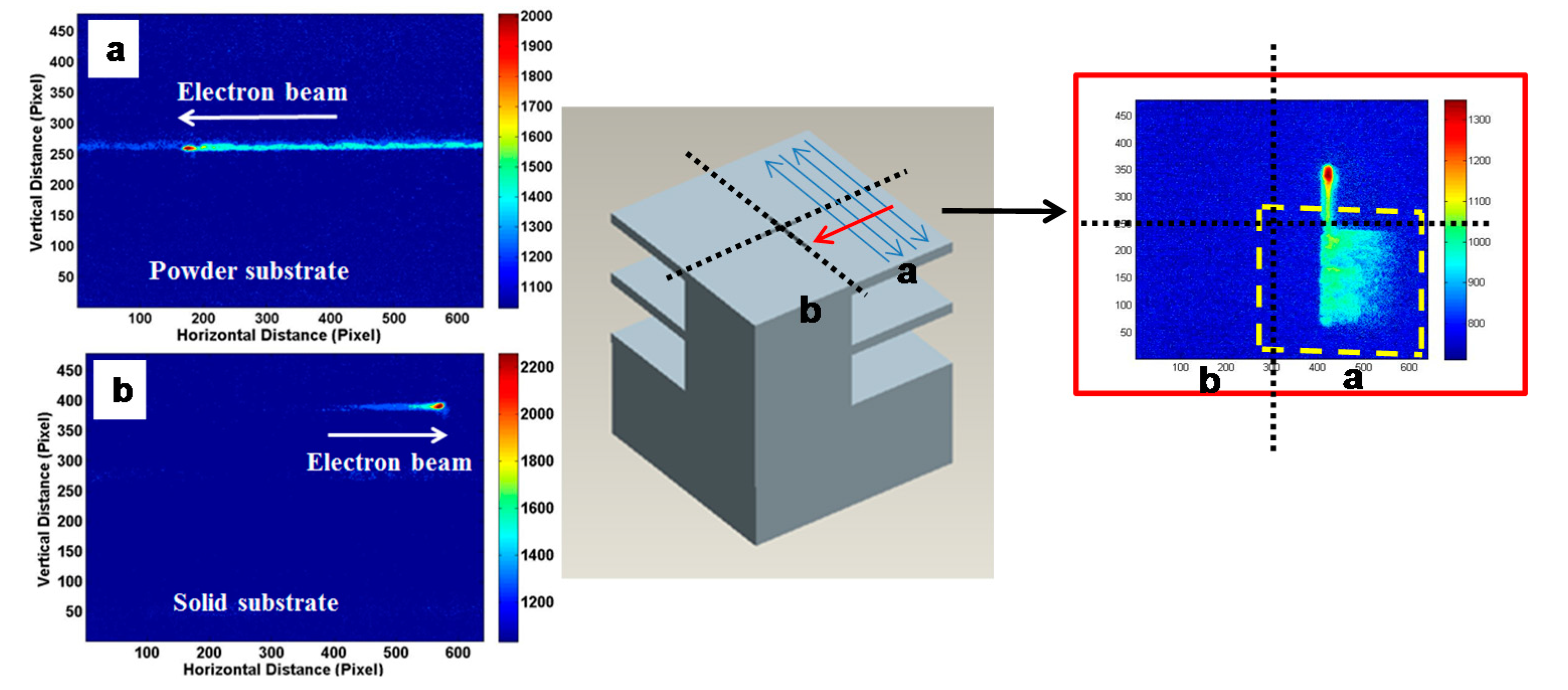
In another experimental study, process temperatures in building overhang features were acquired using a thermal imager [18]. Figure 3 below illustrates a few thermal images, using near-infrared thermography, from building a part with overhang features. It is noted that during the scanning on the overhang side (Figure 3a), the trace of the high temperature zone is much longer than when scanning on top of the solid substrate side (Figure 3b). Moreover, substantial heat retention on the overhang surface is noticed causing a slow heat-fading phenomenon. The overhang area shows warping after the build, as noted earlier in Figure 1.
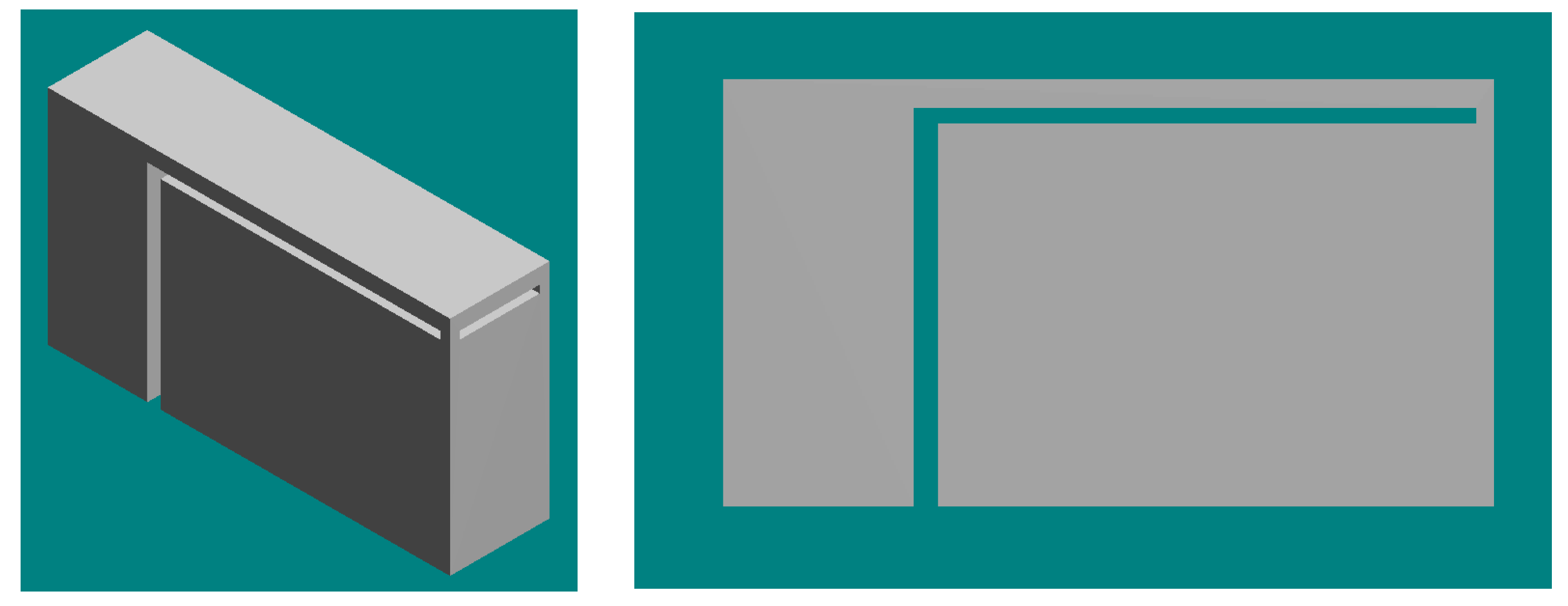
The results from both thermal simulations and experiments pointed out that by modifying the thermal characteristics underneath an overhang may alter the thermomechanical behavior to be more favorable in reducing thermal stresses, and thus, overhang distortions. For example, building a solid piece underneath an overhang, with a small gap (thus, contact-free), may enhance the heat flow and restore the thermal behavior closer to that in the solid substrate area. The concept has been shown feasible as noted below, Figure 4 [19]; the overhang with a heat support has no noticeable warping and the heat support can be detached easily without tedious post-processing.
The objective of this study is to systematically examine the proposed contact-free support, using both numerical and experimental methods, and to test its applicability to different conditions and various overhang geometries. Finite Element (FE) modeling technique was applied to numerically analyze the overhang distortions, without support structures or with a heat support, in EBAM fabrications. In addition, overhang models were designed with different heat support parameters and various overhang shapes and sizes, and further fabricated using a powder-bed EBAM system. The fabricated overhang parts were studied, examined, and compared to evaluate the effectiveness of the designed heat support.
2. Modeling Study—Thermomechanical Simulation for Distortion Analysis
A numerical method was applied to investigate overhang distortion without and with a heat support. A 2D FE thermomechanical model was developed by using ABAQUS to simulate the thermal process induced mechanical distortions in a multi-layer deposition process of an overhang model. Figure 5 shows the geometric domain of a typical overhang model (without and with a heat support), which has a substrate placed in the powder bed. The heat support modeled had a 3 mm thickness with a gap distance (e.g., 0.63 mm, changeable) to the overhang. In this study, a total of three layers was simulated sequentially due to the long computational time.
The element activation technique was applied to simulate the powder-layer adding stage in the multi-layer simulation. The second and third powder layers were modeled at the beginning, but deactivated in the scanning/melting phase of the first layer. The second and third powder layers were reactivated at their corresponding scanning stage. Coupled temperature-displacement elements (CPE4T) were used for the whole model. A finer mesh was applied in the beam scanning path while coarser mesh was used in the regions away from the heat affected zone. The element size in the scanning area was 100 μm × 35 μm (x × y) with the mesh size gradually increased with the distance away from the primary scanning area.
The major analysis steps consist of the pre-heating cycle, the electron beam scanning/melting cycle, and the cooling cycle. A conical volumetric heat source linearly decaying along the y-direction (building direction), and scanning along the x-direction, was applied on the top powder layer for the heating-melting process. Due to the vacuum environment, only radiation was considered for heat transfer between the part and environment. The temperature of the substrate bottom was confined as a constant temperature of Tpreheat (730 °C) as the thermal boundary condition. All the mechanical degrees-of-freedom were confined at the bottom of the solid substrate. In final cooling, all the materials were assumed to be under slow cooling until the temperature dropped to the room temperature of 20 °C. The displacement constraints at the bottom surface of the solid substrate were retained. The material used in this study was Ti-6Al-4V powder and the physical, thermal, and mechanical properties, temperature dependent, were from an earlier study [20], which shows the detail of modeling and simulation methods. In [20], the authors also discussed in details the effect of heat support in reducing the overhang distortions due to enhanced heat dissipation. In essence, the heat support reduces the maximum temperatures and results in more uniform thermal gradients, and thus, lower thermal stresses.
Figure 6 below compares the overhang distortions between (a) without support and (b) with a heat support. The heat support was 3 mm thick with a gap distance of 0.63 mm (nine layers) from the overhang. It is clearly evidenced that warping occurs on the overhang if no support. On the other hand, the addition of a heat support effectively reduces the distortion.
Figure 7 plots the build surface profiles (including the solid substrate and overhang area) in different simulation cases of various gap distances. It is noted that the contact-free heat support can be effective, changing from 0.13 mm to 0.06 mm deflection, i.e., about 50% reduction, when using a suitable gap distance. If the gap distance is too large, the heat dissipation may not be effective.
3. Experimental Testing—Fabrication, Results, and Discussion
A series of experiments was conducted to investigate the effects of the proposed heat support. An EBAM system, S12 from Arcam, located at the Marshall Space Flight Center, was used for part fabrications. The AM process applied was the same in all testing. Standard Ti-6Al-4V powder from Arcam was used, the layer thickness was 0.07 mm, and the Speed Function index (parameter setting) of 36, default for Ti-6Al-4V, was adopted. No process compensation was applied when scanning on the overhang side. The pre-heat setting was 730 °C. After a build was completed, the chamber was cooled overnight to near room temperature before the door was opened, and the build parts and powder-bed were moved to the powder recovery system to remove residual powder. The fabricated overhang parts were examined on the overhang distortions. For the overhang parts fabricated, the model geometry in general had an overall size of 10 mm by 10 mm by ~20 mm (length, width, and height) on the solid substrate side, and the overhang side was a rectangle of 10 mm by 10 mm (unless otherwise specified) with 1.5 mm thickness.
3.1. Overhang Part Fabrication
3.1.1. Effect of Support Structures
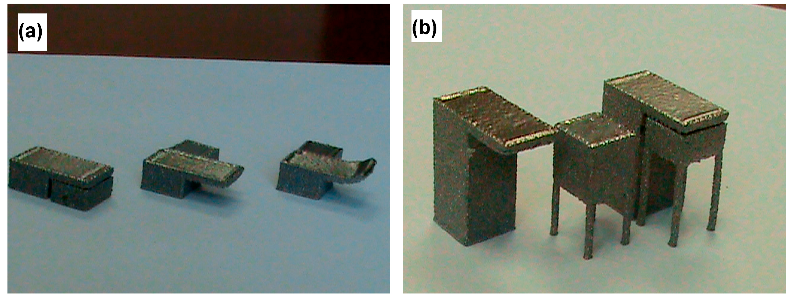
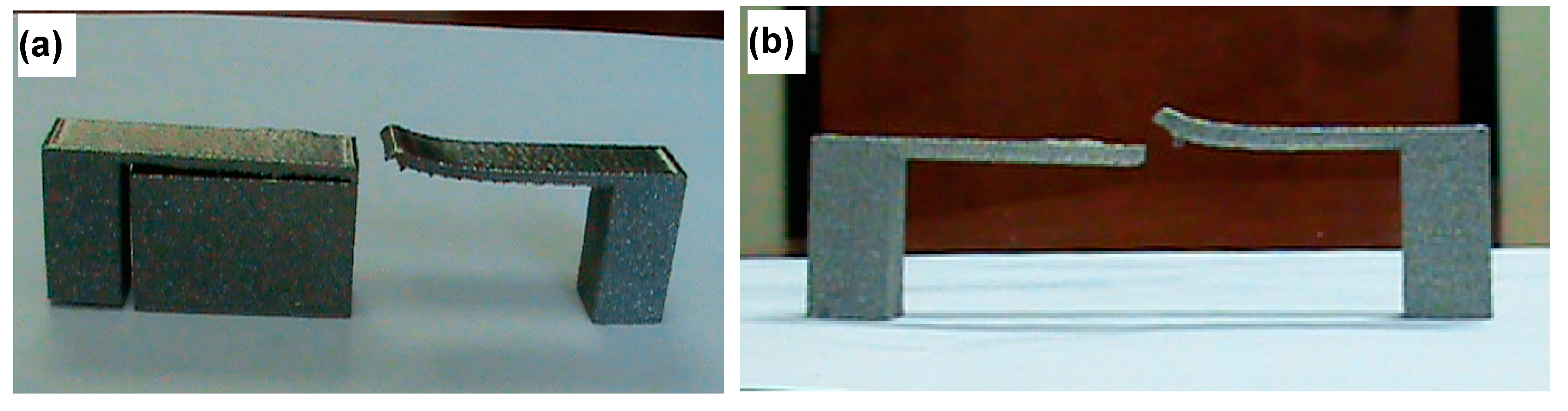
First, overhangs parts with no support, with a conventional support, and with a heat support were fabricated. The conventional support was generated using Magics software giving a tooth-type contact with the overhang, underneath and around the perimeter. Figure 8 shows the CAD model of an overhang with a heat support. The heat support has a 10 mm by 8.7 mm section (length and width) with 19.37 mm in height, and a gap distance of 0.63 mm (9 layers) to the bottom surface of the overhang. The vertical spacing between the side surfaces was about 1.3 mm. After the fabrication, the parts, in one build, were retrieved from the build plate and the powder-bed. For the case with a heat support, the support structure (a solid piece) can be easily detached from the part. The fabricated parts are compared in Figure 9, showing noticeable warping on the free-end of the no-support overhang part, but virtually no or little warping on the overhang part using either conventional support or the proposed heat support. The physical heat support is also shown, separately, in Figure 9. A comparison in a stereoscope clearly shows virtually no warping in the overhang fabricated with a heat support, demonstrating the effectiveness of the heat support.
3.1.2. Heat Support of Different Parameters
For a heat support, two key parameters that are critical to its function are the gap distance and the support thickness. The gap distance governs the enhanced heat flow; the smaller, the better; however, binding between the heat support and the overhang may occur if the gap distance is too small. On the other hand, the thickness of a heat support may also affect its capacity in heat dissipation; ideally, the thicker the better, however, this results in more waste of materials. In one testing, three cases of the gap distance were investigated, 7, 9 and 11 layers (0.49 mm, 0.63 mm, 0.77 mm). A short overall model (5 mm tall), but the same sectional size and shape was used. The result shows, in Figure 10a, that a smaller gap (0.49 mm) results in binding and a larger gap (0.77 mm) was not effective, leading to edge curling. In another testing, different heat support thicknesses were further fabricated: ~10 mm and ~5 mm. The result, shown in Figure 10b, indicates that a 10-mm thick heat support is still effective, but for the case of 5-mm thickness, the heat support was partially fused with the overhang.
3.1.3. Different Overhang Geometries
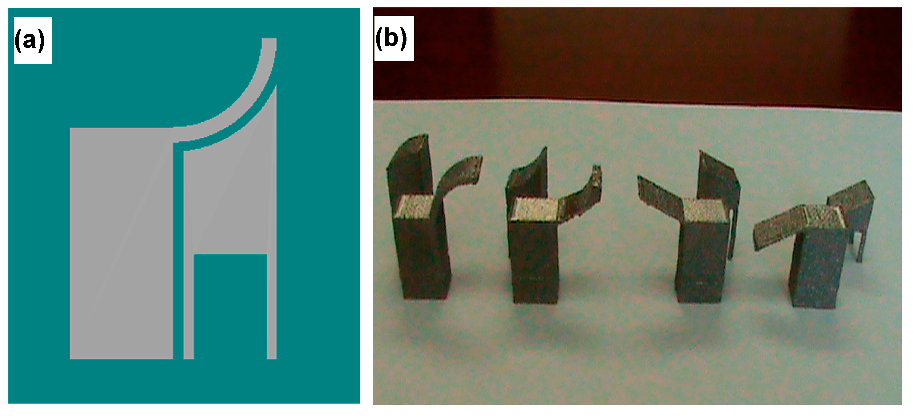
To examine if the heat support concept may be applicable to different geometries, several overhang shapes were modeled, built, and evaluated. The first group involved overhang parts with different overhang angles, either a fixed angle (30° tilted upward or downward) or varying angle along a curve (i.e., curved with a radius of 10 mm). The designed heat support had a constant vertical gap distance, 0.63 mm, along the overhang curve. Figure 11a shows an example of the CAD model (side view) of a curved overhang. The result of fabricated parts is shown in Figure 11b. In general, the heat supports for different overhang curves are effective, keeping overhangs from warping, except that the one with a concave curvature has a rough edge at its free-end.
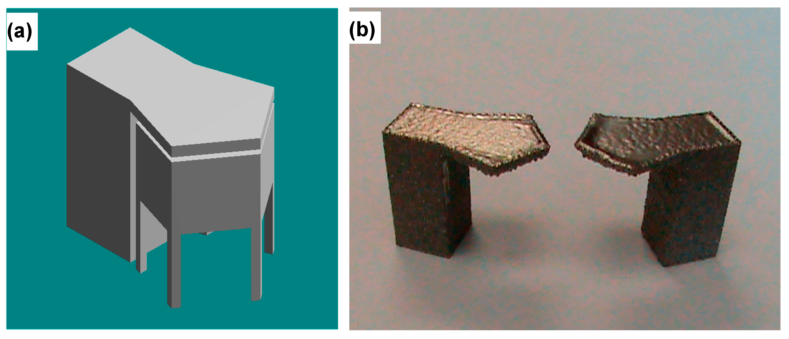
The second group tested has a variety of overhang sectional shapes, ranging from a triangle, to a pentagon, to a circle. The heat support had the same sectional area as the overhang, i.e., a triangular section for a triangle overhang, with a horizontal spacing of 1.3 mm between the side surfaces; shown in Figure 12a is the CAD model of a pentagon-shaped overhang with a heat support. Overall, all three different overhang shapes show that the heat support is effective in reducing overhang distortions. Figure 12b shows the pentagon-shaped overhang with a heat support (left) or with no support (right). Figure 13 further shows side-by-side comparison of overhang distortions between with and without a heat support for three different overhang shapes. It is consistent in that utilizing heat supports was able to reduce overhang distortions.
3.2. Limitations and Challenges
The results presented above prove the potential of the proposed contact-free heat support, capable of distortion minimization with no or little post-processing in removing support structures. Applications to different overhang geometries were demonstrated as well. However, it is also necessary to point out the limitations of such contact-free heat supports. For example, for a longer overhang, a heat support may not be effective to completely eliminate distortion because of a greater thermal-stress induced moment due to the overhang length. However, an alternative approach may be to incorporate minimum contacts, e.g., at the corner of an overhang edge, as a geometric constraint. Figure 14 shows the CAD model of a long overhang (30 mm) with a heat support and two anchors (1 mm by 1 mm square section) at the corners. Figure 15 further shows the fabricated long overhangs with a minimal-contact heat support and without a support structure. It is evident that the long overhang remains warping free in contrast to severe warping for the no support case. Therefore, the minimal-contact heat support concept may be an alternative for very warping-prompt features with a less restricted gap distance requirement.
4. Conclusions
In this study, an original concept of contact-free “heat support” was investigated to develop effective alternative support structures for part overhangs in powder-bed metal AM. FE Thermomechanical modeling and simulations were applied to theoretically analyze the effectiveness of heat supports in overhang distortion minimizations. A powder-bed EBAM system using Ti-6Al-4V powder was utilized to fabricate overhang parts with a heat support, which were subsequently evaluated in overhang distortions. Moreover, different heat support parameters and various overhang geometries were also experimentally evaluated. The major findings are the following.
- (1)
- The contact-free heat support has been demonstrated to be an effective alternative to conventional support structures in minimizing overhang distortions with no or little post-processing needed.
- (2)
- The effectiveness of a heat support is sensitive to the gap distance and the heat support thickness.
- (3)
- The contact-free heat support has also been shown to be effective for various overhang geometries, including different curves and shapes.
This study offers both fundamental understanding and innovations of the heat support concept for pragmatic usage in powder-bed metal AM. The proposed contact-free heat support was validated in the laboratory setting with multiple conditions, and the concept is currently being evaluated by a private additive manufacturing corporation. Therefore, the heat support approach has the potential for implementation in industrial applications in the near future. Future work will study and test the heat support concept extended to complex-shaped components, to different materials, and to other processes such as SLM; if all are successful, it would prove the ability of the heat support to significantly impact powder-bed metal AM technologies.
5. Patents
Chou, K.; Cooper, K. Systems and Methods for Designing and Fabricating Contact-free Support Structures for Overhang Geometries of Parts in Powder-bed Metal Additive Manufacturing, U.S. Patent No. 9,767,224 B2, Date of patent issued: 19 September 2017.
Acknowledgments
The research materials presented in this paper were supported by NASA and NSF. Marshall Space Flight Center, Nonmetallic Branch and Technology Transfer Program, provided assistance and support.
Author Contributions
Shivani Batra and Shelly Sachdeva conceived, formulated and verified the 2D EAV data model. Shivani Batra, Shelly Sachdeva and Subhash Bhalla analyzed the results, proof read the manuscript and corrected the manuscript. Shelly Sachdeva and Subhash Bhalla contributed on experience about openEHR architecture. All authors have read and approved the final manuscript.
Conflicts of Interest
The authors declare no conflict of interest.
References
- ASTM International. ASTM Standard F2792, Standard Terminology for Additive Manufacturing Technologies; ASTM International: West Conshohocken, PA, USA, 2012. [Google Scholar]
- Yadroitsev, I.; Gusarov, A.; Yadroitsava, I.; Smurov, I. Single track formation in selective laser melting of metal powders. J. Mater. Process. Technol. 2010, 210, 1624–1631. [Google Scholar] [CrossRef]
- Tabernero, I.; Lamikiz, A.; Martínez, S.; Ukar, E.; López de Lacalle, L.N. Geometric modelling of added layers by coaxial laser cladding. Phys. Procedia 2012, 39, 913–920. [Google Scholar] [CrossRef]
- Tabernero, I.; Lamikiz, A.; Ukar, E.; Martinez, S.; Celaya, A. Modeling of the geometry built-up by coaxial laser material deposition process. Int. J. Adv. Manuf. Technol. 2014, 70, 843–851. [Google Scholar] [CrossRef]
- Mercelis, P.; Kruth, J.-P. Residual stresses in selective laser sintering and selective laser melting. Rapid Prototyp. J. 2006, 12, 254–265. [Google Scholar] [CrossRef]
- Mumtaz, K.A.; Hopkinson, N.; Stapleton, D.; Todd, I.; Derguti, F.; Vora, P. Benchmarking metal powder bed additive manufacturing processes (SLM and EBM) to build flat overhanging geometries without supports. In Proceedings of the 23rd Annual International Solid Freeform Fabrication Symposium, Austin, TX, USA, 6–8 August 2012. [Google Scholar]
- Yan, C.; Hao, L.; Hussein, A.; Raymont, D. Evaluations of cellular lattice structures manufactured using selective laser melting. Int. J. Mach. Tools Manuf. 2012, 62, 32–38. [Google Scholar] [CrossRef]
- Jhabvala, J.; Boillat, E.; André, C.; Glardon, R. An innovative method to build support structures with a pulsed laser in the selective laser melting process. Int. J. Adv. Manuf. Technol. 2012, 59, 137–142. [Google Scholar] [CrossRef]
- Hussein, A.; Hao, L.; Yan, C.; Everson, R.; Young, P. Advanced lattice support structures for metal additive manufacturing. J. Mater. Process. Technol. 2013, 213, 1019–1026. [Google Scholar] [CrossRef]
- Hussein, A.; Yan, C.; Everson, R.; Hao, L. Preliminary investigation on cellular support structures using SLM process. In Proceedings of the Innovative Developments in Virtual and Physical Prototyping, Leiria, Portugal, 28 September–1 October 2011; da Silva Bartolo, P.J., Ed.; Taylor & Francis Group: London, UK, 2011; pp. 609–612. [Google Scholar]
- Strano, G.; Hao, L.; Everson, R.M.; Evans, K.E. A new approach to the design and optimisation of support structures in additive manufacturing. Int. J. Adv. Manuf. Technol. 2013, 66, 1247–1254. [Google Scholar] [CrossRef]
- Calignano, F. Design optimization of supports for overhanging structures in aluminum and titanium alloys by selective laser melting. Mater. Des. 2013, 64, 203–213. [Google Scholar] [CrossRef]
- Krol, T.A.; Zaeh, M.F.; Seidel, C. Optimization of supports in metal-based additive manufacturing by means of finite element models. In Proceedings of the 23rd Solid Freeform Fabrication Symposium, Austin, TX, USA, 6–8 August 2012; pp. 707–718. [Google Scholar]
- Thomas, D. The Development of Design Rules for Selective Laser Melting. Ph.D. Thesis, University of Wales, Cardiff, UK, 2009. [Google Scholar]
- Cloots, M.; Spierings, A.; Wegener, K. Assessing new support minimizing strategies for the additive manufacturing technology SLM. In Proceedings of the 24th Annual Solid Freeform Fabrication Symposium, Austin, TX, USA, 12–14 August 2013. [Google Scholar]
- Buchbinder, D.; Meiners, W.; Pirch, N.; Wissenbach, K.; Schrage, J. Investigation on reducing distortion by preheating during manufacture of aluminum components using selective laser melting. J. Laser Appl. 2014, 26, 012004. [Google Scholar] [CrossRef]
- Shen, N.; Chou, K. Thermal modeling of electron beam additive manufacturing process—Powder sintering effect. In Proceedings of the ASME International Manufacturing Science and Engineering Conference, Notre Dame, IN, USA, 4–8 June 2012; pp. 287–295. [Google Scholar]
- Price, S. On Temperature Measurements and Analysis in Electron Beam Additive Manufacturing Using Near Infrared Thermography. Master’s Thesis, The University of Alabama, Tuscaloosa, AL, USA, May 2014. [Google Scholar]
- Chou, K.; Cooper, K. Systems and Methods for Designing and Fabricating Contact-Free Support Structures for Overhang Geometries of Parts in Powder-bed Metal Additive Manufacturing. U.S. Patent No. 9,767,224 B2, 17 September 2017. [Google Scholar]
- Cheng, B.; Chou, K. Geometric consideration of support structures in part overhang fabrications by electron beam additive manufacturing. Comput. Aided Des. 2015, 69, 102–111. [Google Scholar] [CrossRef]
Figure 1.
An example of overhang warping and mitigation using conventional support.
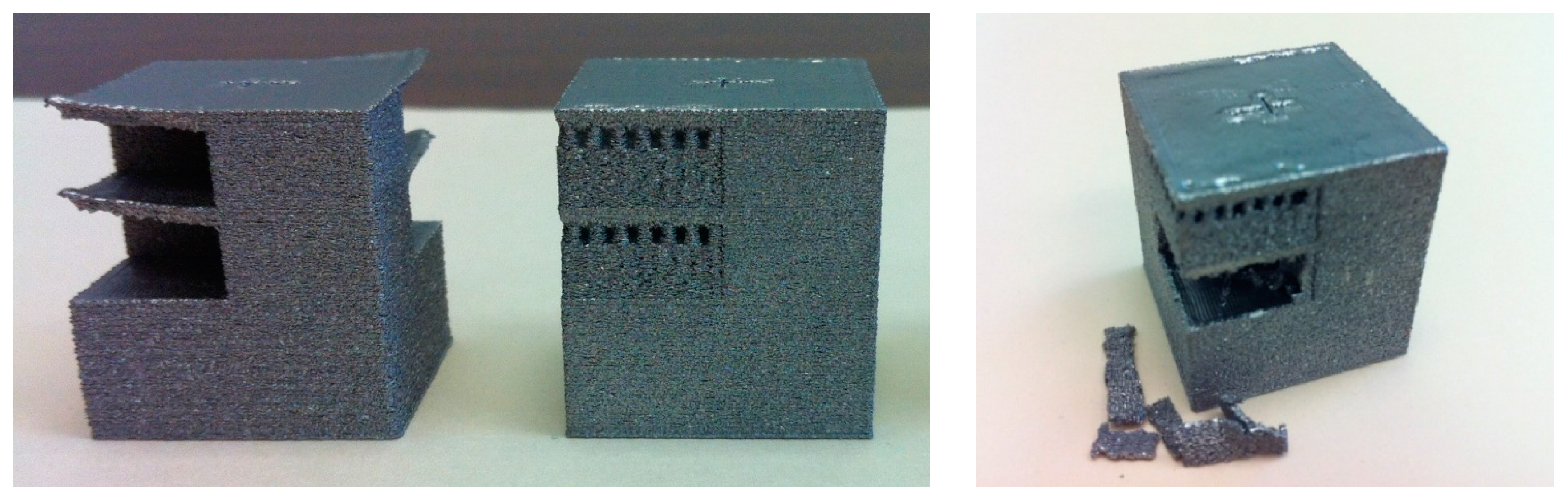
Figure 2.
Thermal response from simulations of electron beam additive manufacturing (EBAM)-fabricating an overhang part.
Figure 2.
Thermal response from simulations of electron beam additive manufacturing (EBAM)-fabricating an overhang part.
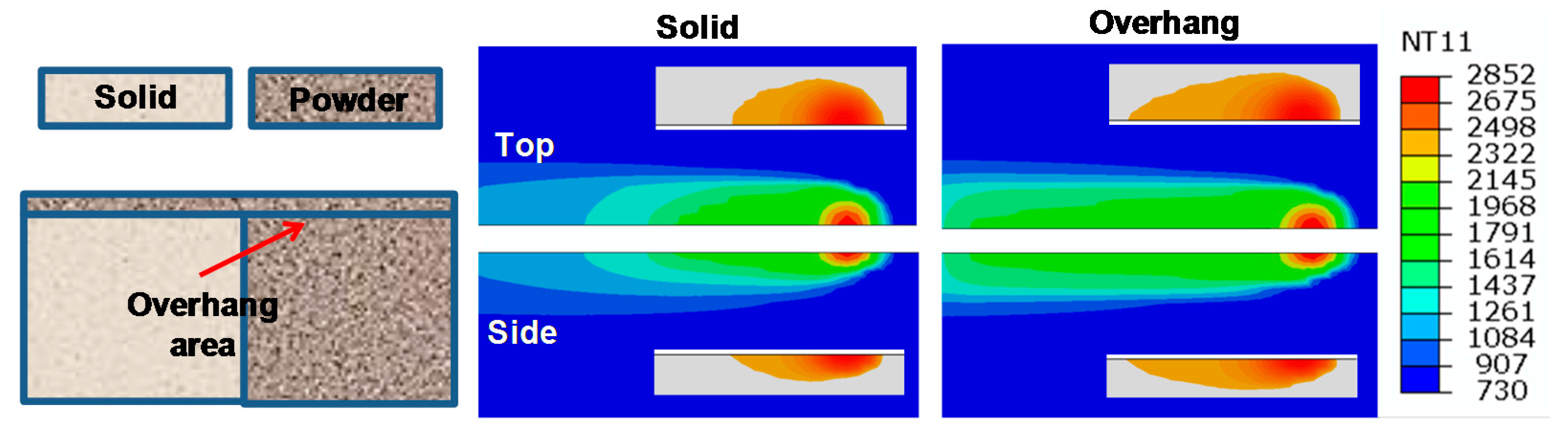
Figure 3.
Thermal images from building overhang-type features, showing drastically different temperature distributions between scanning on a solid substrate and on an overhang. Left 2 images: temperature contour in scanning the powder and solid substrates (a,b); Middle image: illustration of the beam scanning pattern (blue arrow: scanning direction, red arrow: rastering direction); Right image: Temperature contour showing substantial heat retention on the overhang surface.

Figure 4.
An example of (a) contact-free heat support in an overhang model and (b) the fabricated overhang without distortion (Red circle indicating the overhang area).
Figure 4.
An example of (a) contact-free heat support in an overhang model and (b) the fabricated overhang without distortion (Red circle indicating the overhang area).

Figure 5.
Overhang model geometry used in simulations: (a) without and (b) with a heat support.
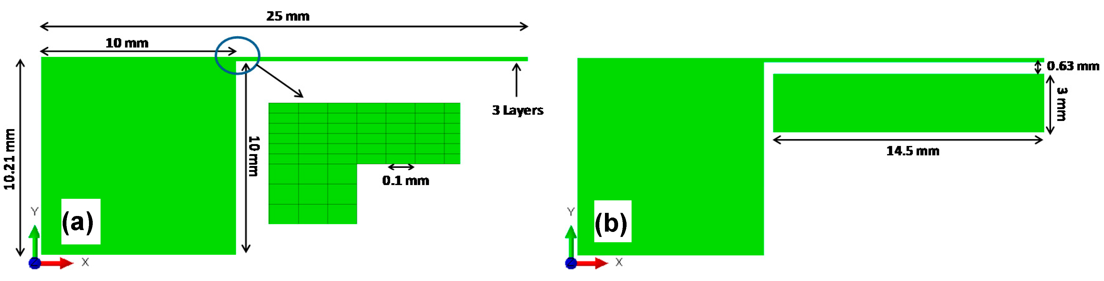
Figure 6.
Overhang part deflection (y) examples: (a) without support and (b) with heat support.
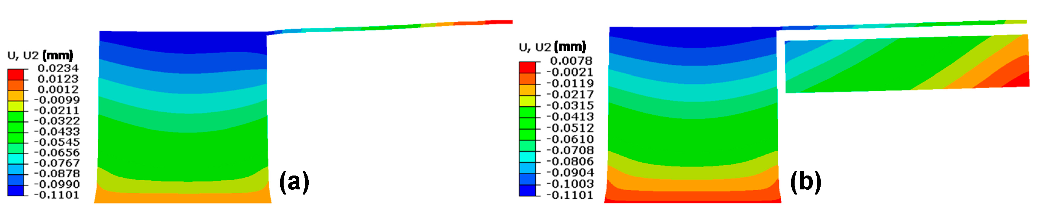
Figure 7.
Overhang part surface profile comparison between different heat-support cases.
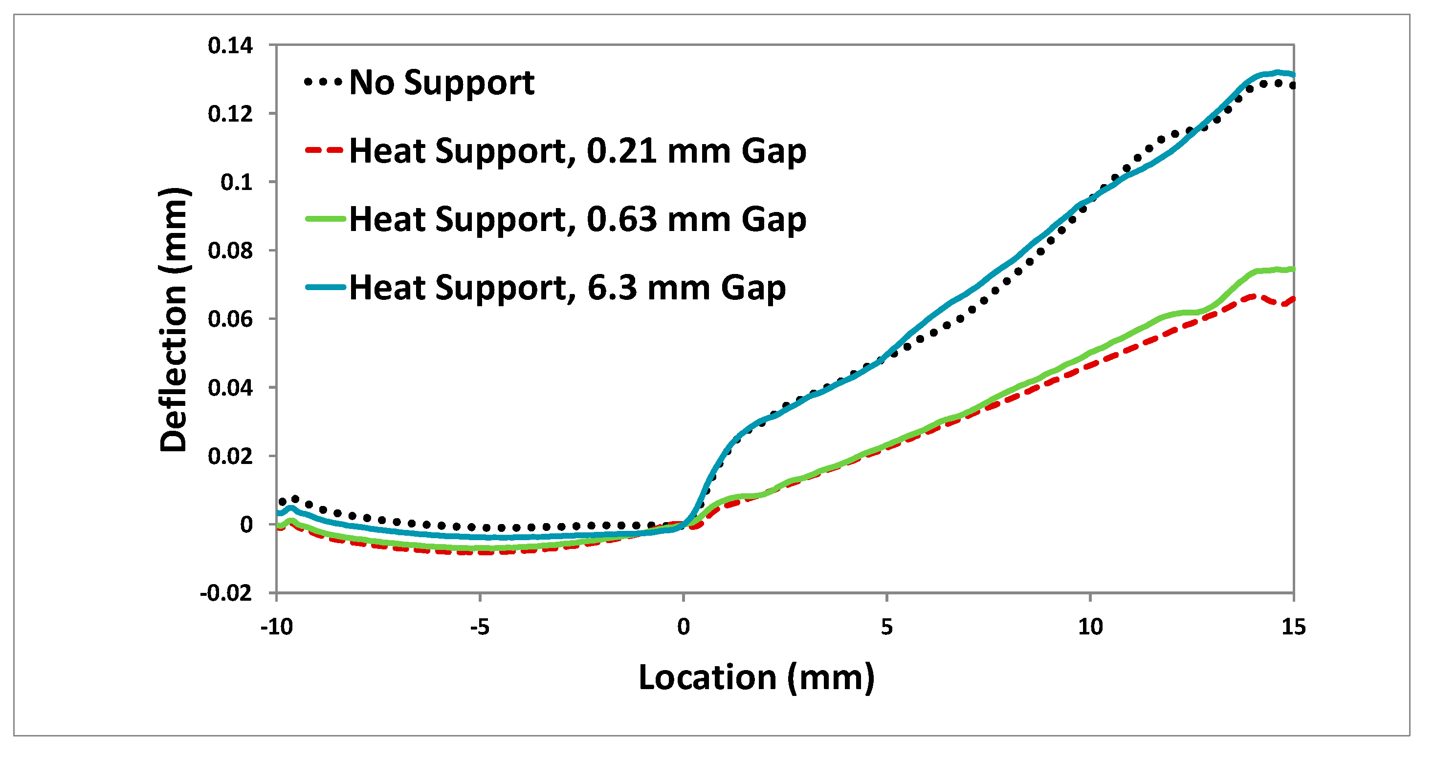
Figure 8.
Computer-aided design (CAD) model of an overhang part with a heat support.
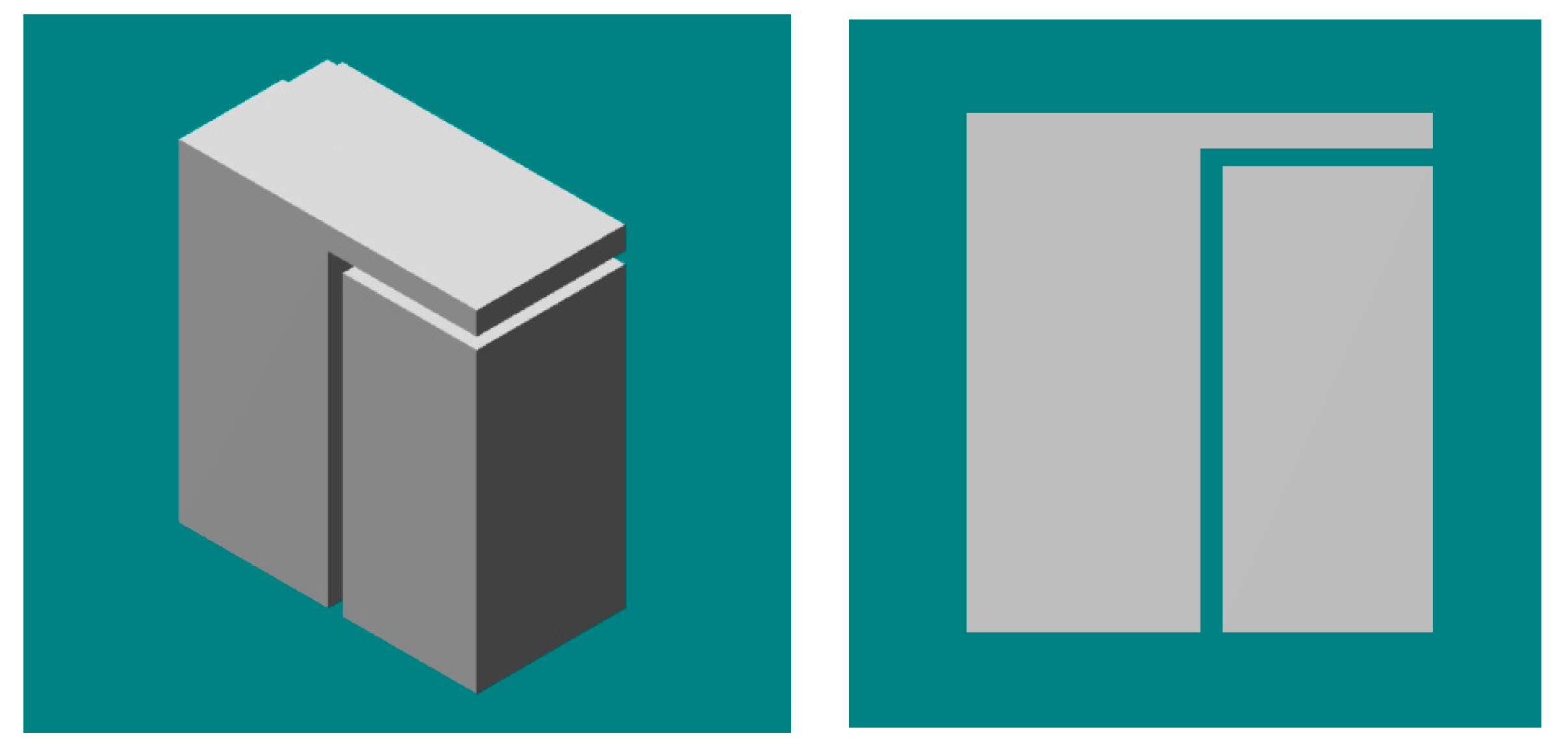
Figure 9.
(a) Fabricated overhang parts with no support, conventional support or heat support. Overhang warping between without and with heat support: (b) Side-by-side comparison, and (c) comparison in stereoscope.
Figure 9.
(a) Fabricated overhang parts with no support, conventional support or heat support. Overhang warping between without and with heat support: (b) Side-by-side comparison, and (c) comparison in stereoscope.
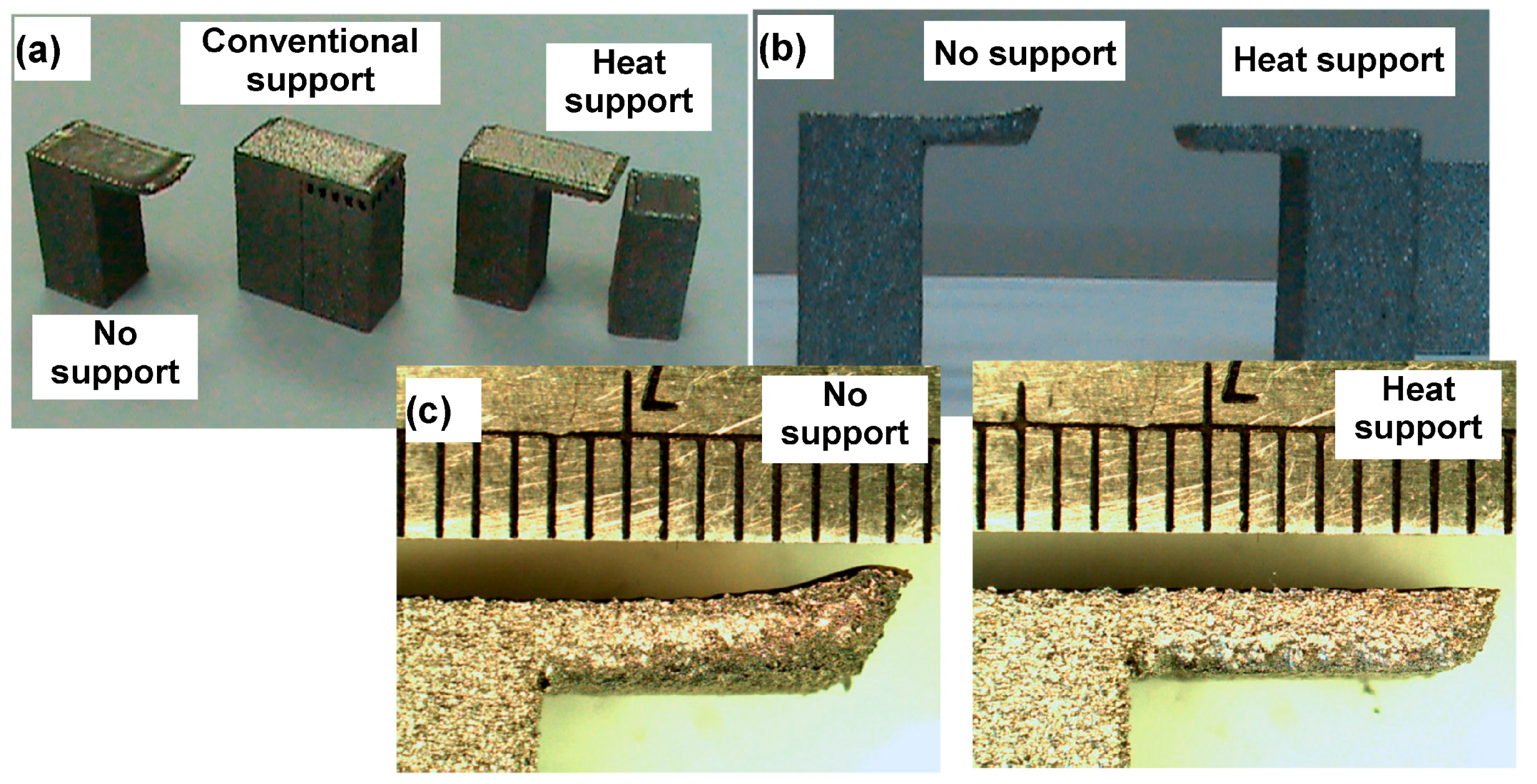
Figure 10.
(a) Fabricated overhang parts using heat supports with different gap distances, from Left to Right: 7, 9, and 11 layers; (b) Overhangs with heat support of different thicknesses: 10 mm (left) and 5 mm (right).
Figure 10.
(a) Fabricated overhang parts using heat supports with different gap distances, from Left to Right: 7, 9, and 11 layers; (b) Overhangs with heat support of different thicknesses: 10 mm (left) and 5 mm (right).

Figure 11.
(a) Example of CAD model of a curved overhang; (b) Fabricated overhang parts, using heat supports, with different geometries, from Left to Right: Convex curve, concave curve, 30° slope upward and downward.
Figure 11.
(a) Example of CAD model of a curved overhang; (b) Fabricated overhang parts, using heat supports, with different geometries, from Left to Right: Convex curve, concave curve, 30° slope upward and downward.

Figure 12.
(a) CAD model of pentagon-shaped overhang; (b) Fabricated overhang: with (Left) and without heat support (Right).
Figure 12.
(a) CAD model of pentagon-shaped overhang; (b) Fabricated overhang: with (Left) and without heat support (Right).

Figure 13.
Overhang distortion comparison between with heat support (Left) and without support (Right) for different overhang shapes: (a) Triangle; (b) pentagon; (c) and circle.
Figure 13.
Overhang distortion comparison between with heat support (Left) and without support (Right) for different overhang shapes: (a) Triangle; (b) pentagon; (c) and circle.
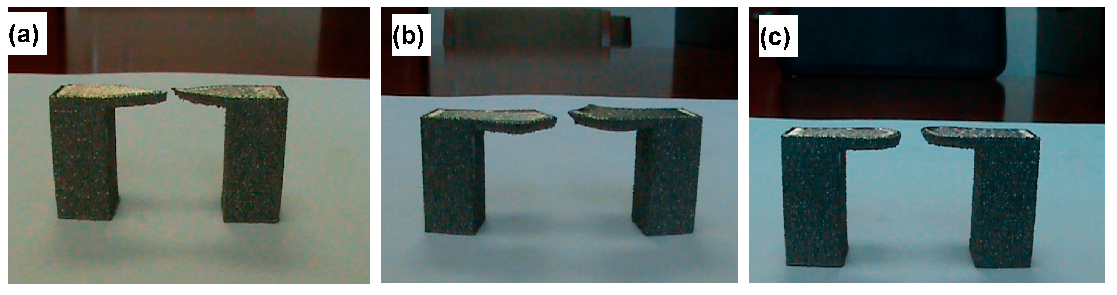
Figure 14.
CAD model of a long overhang with heat support plus anchors.

Figure 15.
Fabricated long overhang parts: (a) Isometric view comparison; and (b) side view comparison. In both, Left: with minimum-contact heat support, and Right: without support.
Figure 15.
Fabricated long overhang parts: (a) Isometric view comparison; and (b) side view comparison. In both, Left: with minimum-contact heat support, and Right: without support.

© 2017 by the authors. Licensee MDPI, Basel, Switzerland. This article is an open access article distributed under the terms and conditions of the Creative Commons Attribution (CC BY) license (http://creativecommons.org/licenses/by/4.0/).
Share and Cite
MDPI and ACS Style
Cooper, K.; Steele, P.; Cheng, B.; Chou, K. Contact-Free Support Structures for Part Overhangs in Powder-Bed Metal Additive Manufacturing. Inventions 2018, 3, 2. https://doi.org/10.3390/inventions3010002
AMA Style
Cooper K, Steele P, Cheng B, Chou K. Contact-Free Support Structures for Part Overhangs in Powder-Bed Metal Additive Manufacturing. Inventions. 2018; 3(1):2. https://doi.org/10.3390/inventions3010002
Chicago/Turabian StyleCooper, Kenneth, Phillip Steele, Bo Cheng, and Kevin Chou. 2018. "Contact-Free Support Structures for Part Overhangs in Powder-Bed Metal Additive Manufacturing" Inventions 3, no. 1: 2. https://doi.org/10.3390/inventions3010002