Constructal Design of a Rectangular Fin in a Mixed Convective Confined Environment


School of Engineering, Newcastle University, Newcastle upon Tyne NE1 7RU, UK
*
Author to whom correspondence should be addressed.
Inventions 2018, 3(2), 27; https://doi.org/10.3390/inventions3020027
Submission received: 27 March 2018
/
Revised: 20 April 2018
/
Accepted: 27 April 2018
/
Published: 3 May 2018
(This article belongs to the Special Issue Heat Transfer and Its Innovative Applications)
Abstract
:Extended surfaces or fins offer an efficient solution in many engineering situations that demand a higher heat transfer, including cooling gas-turbine components and electronic chips via internal convective flows. However, fins require a higher active surface area for higher heat transfer, which may not be always feasible in a confined environment. A feasible solution to enhance heat transfer from fins can be the use of nanofluids, which are the combination of a fluid base and nanoparticles. The main purpose of this study is, therefore, to optimize a rectangular fin intruded into the mixed convective confined space filled with a nanofluid and by means of constructal design. Here, a two-dimensional macroscopic numerical model has been developed for Al2O3–water nanofluid to investigate the heat transfer and fluid flow inside a square confined-space with an intruded rectangular fin and to optimize the fin geometry for maximizing the heat transfer using the constructal design method. The flow fields, temperature fields, heat transfer rates, and the transition from forced to mixed convection are examined for different values of Rayleigh and Reynolds numbers for various fin geometries in order to maximize the heat transfer from the fin to the surrounding nanofluid flow. The outcome of this study provides important insights into the constructal design method for the confined environment, which would be beneficial in developing novel fin geometries with enhanced and controlled heat-transfer for engineering problems, including cooling gas-turbine components and electronic chips.
1. Introduction
The study of convective heat transfer of conventional heat-transfer fluids in confined spaces has drawn an enormous attention of researchers for a long period of time due to its wide variety of the engineering and industrial applications (such as solar collectors, nuclear reactors, and food processing) [1,2,3,4,5,6,7,8,9,10,11,12]. However, conventional heat-transfer fluids (such as water, ethylene glycol, and engine oil) have limited capabilities in term of thermal properties. Conversely, solids, such as Al2O3, SiO2, TiO2, and CuO, have much higher thermal conductivities compared to that of conventional heat-transfer fluids. Thus, researchers have proposed various nanofluids utilizing the higher thermal properties of solid nanoparticles in order to enhance the thermal performance. Nanofluids are suspensions of nano-sized solid particles in base fluids that can have higher thermal properties compared to that of base fluids, making them more efficient for heat transfer applications. Over the past years, many studies have been conducted for nanofluids for showing their better thermal properties and thermal performances as well as for understating the mechanisms of heat transport in nanofluids [13,14,15,16,17,18]. For instance, Eastman and co-authors [13] showed that a significant improvement in thermal conductivity of CuO–water nanofluid with 5% of nanocrystalline CuO particles suspended in water. Conversely, Buongiorno [14] provided an explanation for the abnormal heat transfer coefficient increases with nanoparticle concentrations. It was concluded that the nanofluid properties vary within the boundary layer because of the effect of the temperature gradient and thermophoresis. Ghasemi and Aminossadati [16] presented a numerical study of an inclined enclosure filled with CuO–water nanofluid and it was concluded that heat transfer could be improved by the addition of nanoparticles into the base fluid but there would be an optimum solid volume fraction that maximizes the heat transfer rate. Recently, Bouhalleb and Abbassi [18] showed similar results to those of Ghasemi and Aminossadati [16]. It was shown that the size of the nanoparticles is a more critical parameter than the concentration itself. However, the effect of the particle size will be negligible for low nanoparticles concentrations. Thus, there will be a tradeoff between the heat transfer enhancement due to the change of conductivity, specific heat capacity, and other thermophysical properties of nanofluids for low nanoparticles concentrations. Nevertheless, nanofluids have been considered as advanced heat transfer fluids for many industrial applications (including cooling of electronic components, production machinery, and combustion engines as well as petroleum refineries and power generation, lubrication technologies, food processing, and nuclear reactor cooling) due to their higher heat transfer capabilities [19,20,21,22,23,24].
A significant amount of research efforts, both numerical and experimental, has been devoted to understanding the convective heat transfer and fluid flow of conventional heat transfer fluids in cavities. For example, convective heat transfer inside cavities has been analyzed for triangular, trapezoidal, cylindrical, square, and wavy cavities by many researchers [1,2,3,4,5,6,7,25,26,27,28,29]. Particularly the studies done by Mahmud and co-authors [3,4,5] and Nardini and co-authors [28] for square and wavy cavities provided a better understanding of the physics regarding the fluid flow and heat transfer in cavities and thermal enhancement and optimization. In comparison, less effort is given to understand the convective heat transfer of nanofluids in cavities, in spite of several benefits of nanofluids, which can be highly beneficial for solar collectors and electronic cooling devices to enhance heat transfer [16,19,20,21,24]. Most of these studies, however, dealt with natural convection of nanofluids and it was shown that the heat transfer rate increases for the natural convection in cavities with the increase of nanoparticle concentration. Especially, Jou and Tzeng [20] studied natural convection in rectangular enclosures and showed that the buoyancy parameter and volume fraction of nanofluids cause an increase in the average heat transfer coefficient, while Oztop and Abu-Nada [21] studied natural convection in partially heated rectangular enclosures filled with various nanofluids and a similar conclusion was made. In addition, a decent amount of effort has been devoted to understanding the mixed convective flow and heat transfer in cavities filled with nanofluids [22,23,30,31,32]. For example, Abu-Nada and Chamkha [32] studied mixed convection flow of a nanofluid in a wavy wall cavity and demonstrated that the presence of nanoparticles produced a significant heat transfer augmentation. However, the study of geometric optimization of rectangular fins with the nanofluid and constructal design method is elusive. In the past, the constructal design has guided researchers toward the discovery of efficient cooling structures for various cavities [33,34,35,36]. Previous constructal design studies were primarily based on air- or water-filled cavities. It was not employed to the geometry optimization of fins inside cavities filled with nanofluids. Therefore, the main purpose of this study is to investigate the geometrical optimization of fins in confined spaces filled with nanofluids by means of the constructal design concept.
In the present study, a two-dimensional, steady-state macroscopic mixture model has been employed to investigate heat transfer and fluid flow of Al2O3–water nanofluid in a square lid-driven cavity with an intruded rectangular fin and to optimize a constant temperature rectangular fin for maximizing the heat transfer using the constructal design method. The macroscopic mixture model has been widely used by many researchers to study nanofluid heat transfer with low-particle concentration as it provides reasonably accurate results with less computing power and time [21,22,23,24,32,37,38]. Thus, the macroscopic model is the best suited for the present study. Although we have been working with multiple water-based nanofluids, we have considered Al2O3–water nanofluid for the present study, as Al2O3–water nanofluid often shows superior performances over CuO–water or other water-based nanofluids. In addition, Al2O3 nanoparticles in water are less prone to deposition than CuO nanoparticles. According to the constructal design method, optimization of fins in confined spaces can be subjected to two constraints, namely, the total fin area constraint and the confined space area constraint, while the degrees of freedom are the fin and confined space aspect ratios. For these degrees of freedom, several values of the Rayleigh (Ra) and Reynolds (Re) numbers are considered in examining flow fields, temperature fields, and heat transfer.
2. Mathematical and Numerical Modeling
2.1. Governing Equations
The governing equations for the laminar, two-dimensional, steady-state mixed convective fluid flow and heat transfer with the Boussinesq approximation in the y-direction are written for Al2O3–water nanofluid as [39]:
where u and v are the horizontal and vertical velocities, p is the thermodynamic pressure, μnf is the dynamic viscosity, ρnf is the mass density, βnf is the thermal expansion coefficient, T is the temperature, g is the gravitational acceleration, knf is the heat conductivity, and (cp)nf is the heat capacity. The subscript nf represents the effective nanofluid properties. The following assumptions are adopted for the above-mentioned governing equations:
- (i)
- the heat due to friction between the nanoparticles and base fluid is negligible compared to conduction at the heated surface, i.e., the viscous dissipation of energy is negligible,
- (ii)
- both the fluid phase and nanoparticles are in a thermal equilibrium and flowing at the same velocity,
- (iii)
- nanofluid is Newtonian whose thermophysical properties are assumed to be constant, and
- (iv)
- the Brownian motion of nanoparticles, aggregation of nanoparticles, and the nanoparticle size effects are neglected for simplification by considering low operating temperature and low nanoparticle concentration.
These assumptions are in-line with other modeling efforts and we have found that these assumptions are appropriate for the present study. Since the present macroscopic model does not include the particle size, one would expect some deviation with experimental results when the particle sizes are either too small or too large. Nevertheless, the macroscopic numerical model will provide some important insights into the mixed convective heat transfer behavior of Al2O3–water nanofluid, which can be useful in developing novel fin geometries with enhanced and controlled heat-transfer for engineering problems.
The thermophysical properties of Al2O3–water nanofluid, namely, thermal conductivity, density, viscosity, and specific heat, are estimated using the correlations/models that are widely used for nanofluids with low particle concentrations [21,22,23,24,32,40]. Specifically, the effective dynamic viscosity of Al2O3–water nanofluid is calculated according to the Brinkman model [41,42] and the effective thermal conductivity is determined using the Maxwell model [43,44,45]. The expressions for nanofluid effective dynamic viscosity (μnf) and effective thermal conductivity (knf) are given as:
where μnf and μf are the dynamic viscosity of nanofluid and base fluid, respectively, ϕ is the volume fraction of Al2O3 nanoparticles in water, and ks and kf are the thermal conductivity of Al2O3 nanoparticles and base fluid, respectively. The nanofluid density, the specific heat at constant pressure, and the coefficient of thermal expansion are calculated according to the mixing theory by the following relations [43,44,45,46,47,48,49,50]:
where the subscripts s and f denote solid nanoparticle and base fluid (in this case water), respectively. It is worthwhile to note that heat capacity and density of Al2O3–water nanofluid depend on the concentration of Al2O3 nanoparticles in water and are unrelated to nanoparticle morphology (size, shape etc.). However, both thermal conductivity and viscosity can be influenced by the shape and size of the Al2O3 nanoparticles, which are negligible in the present investigation due to low operating temperature and low nanoparticles concentration. The effective nanofluid properties are estimated as functions of nanoparticle concentration and the thermophysical properties of water and Al2O3 nanoparticles. The thermophysical properties of water and Al2O3 nanoparticles that are used in determining the effective nanofluid properties are listed in Table 1 [21,39].
2.2. Problem Description
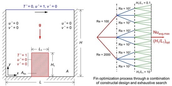
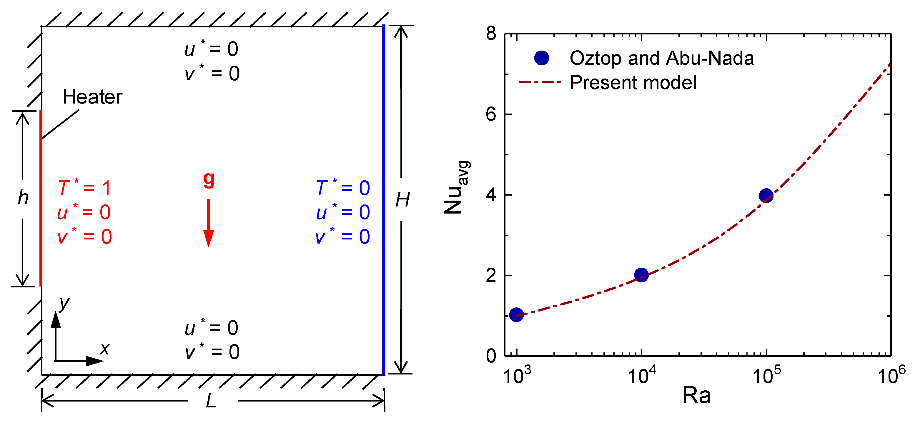
The present problem considers a lid-driven square cavity with a rectangular fin intruded in its bottom center as shown in Figure 1. The top surface (lid) of the cavity moves in the x-axis direction with a velocity of umax and a constant temperature (Tmin) is defined on it. The fin surface has a constant wall temperature (Tmax) boundary condition, which is higher than the lid temperature. In Figure 1, H and L are the height and length of the cavity, H1 and L1 are the height and length of the fin, and A and Afin are the areas of the cavity and the fin, respectively. All other surfaces are considered adiabatic and the no-slip condition is applied everywhere. The dimensionless velocities (u* and v*) and temperature (T*) denoted in Figure 1 are defined as:
For the geometric evaluation with constructal design, the degrees of freedoms for the present problem, which can influence the heat transfer performances, are the cavity area (HL) and fin area (H1L1). The fraction between fin and cavity areas is defined by the equation given below, which is kept constant at 0.05 for the base case and varied between 0.05 and 0.15 for the other cases.
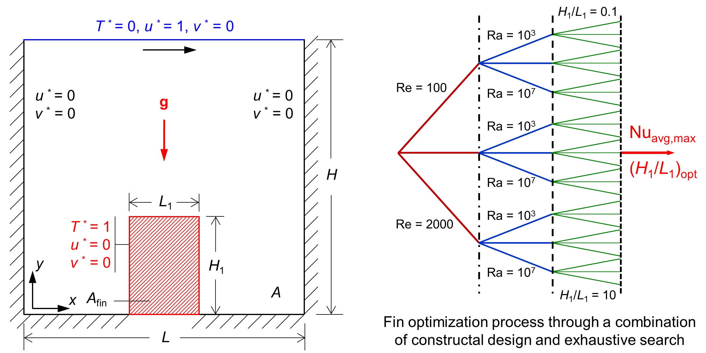
The search for optimized fin configuration is conducted by using a combination of constructal design and exhaustive search [51,52], i.e., examining all the possible configurations as shown in Figure 2. Here, the area of the cavity is kept fixed and different fin aspect ratios (H1/L1) are tested to find the optimum aspect ratio ((H1/L1)opt) and corresponding Nusselt number (Nuavg,max). A set of nondimensional numbers is used to modify the relation between the buoyancy and inertial forces. These parameters are Reynolds (Re), Rayleigh (Ra), Prandtl (Pr), and Richardson (Ri) numbers. All these dimensionless numbers change with nanoparticles concentrations. Thus, these dimensionless numbers are defined using nanofluid properties instead of base-fluid properties, as follows:
where αnf is the thermal diffusivity and νnf is the kinematic viscosity of the nanofluid. For different buoyancy forces considered in this study, the Rayleigh numbers are varied between 103 and 107. For different inertial forces, the Reynolds numbers are varied between 100 and 2000. Finally, the average Nusselt number (Nuavg) is calculated through the integration of the local Nusselt number (NuH) over the fin surface, as follows:
where S′ denotes the fin surface and hnf is the effective heat transfer coefficient of the nanofluid. To better understand the effect of the addition of nanoparticles in base fluid, an effective average Nusselt number is defined in addition to the local and average Nusselt number of Equation (13):
where knf and kf are the thermal conductivities of nanofluid and base fluid, respectively.
3. Numerical Methods and Model Verification
The numerical solution is obtained by solving the governing equations with associated boundary conditions using ANSYS-Fluent [53]. A second-order upwind scheme is used for the spatial discretization of the aforementioned equations. Further, the velocity–pressure coupling is done by the SIMPLE algorithm and the pressure based solver is used to compute the solution [54]. The convergence criteria were set such that when the residuals were smaller than 10−8 for the energy equation and 10−6 for the mass and momentum equations the solution was considered converged.
3.1. Mesh Sensitivity Test
To ensure the simulation results presented in this paper are independent of mesh sizes, a rigorous mesh sensitivity test was conducted for different fin sizes with various meshes (uniform and non-uniform meshes, with or without biases) and various conditions. For all the cases, we observed that the results were within 1% for higher mesh numbers (over 10,000 meshes). No numerical issues were observed during the simulations, except the corner of the fin, and all the cases were converged within the convergence criteria.
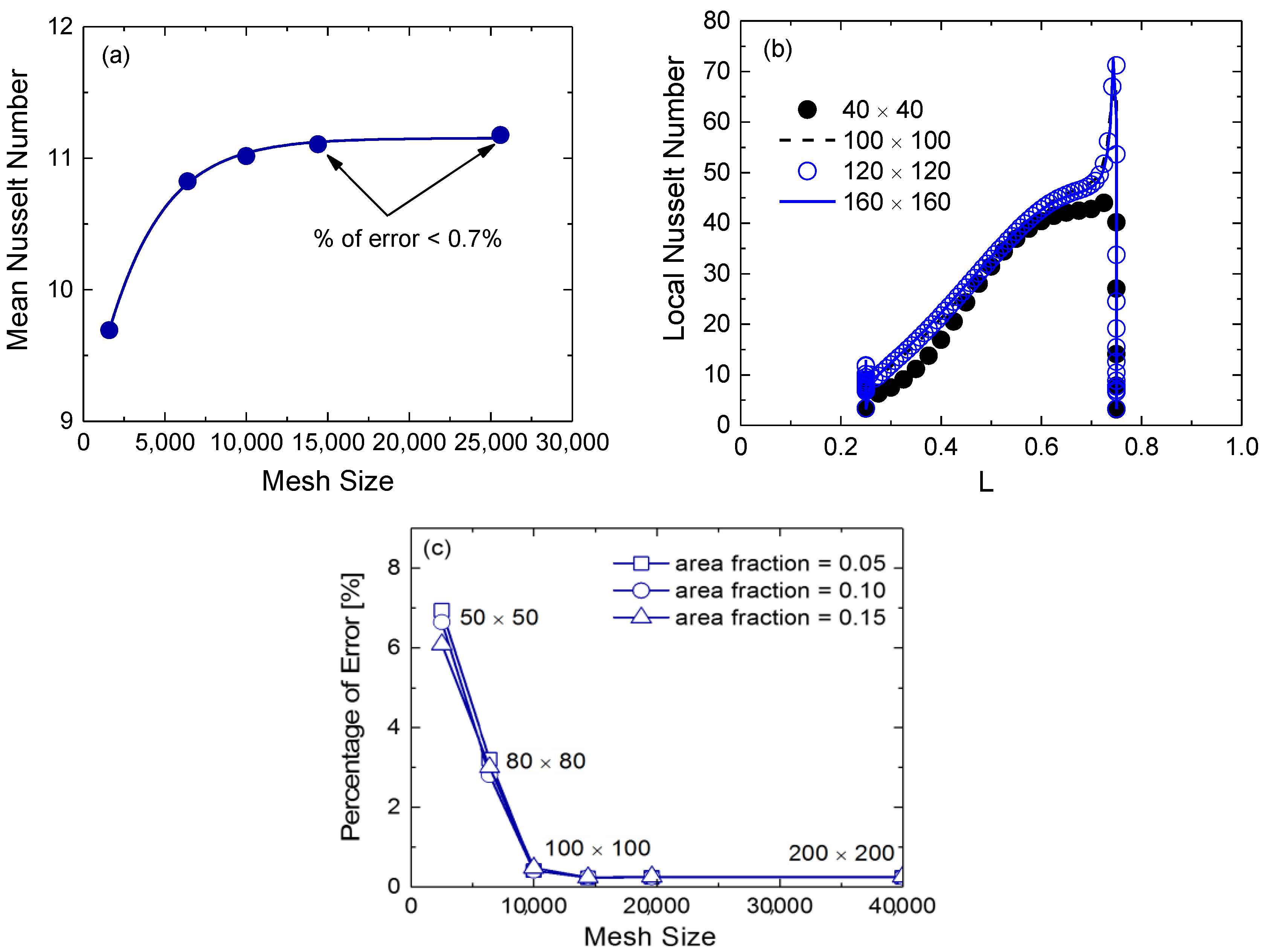
The results of a typical mesh sensitivity test for non-uniform meshes are shown in Figure 3 for three cases. Figure 3a shows the results for mesh densities of 40 × 40, 80 × 80, 100 × 100, 120 × 120, and 160 × 160. Here, the mean Nusselt number between the fin and top wall of Figure 1 is reported for Ra = 105, H1/L1 = 0.5, and ϕ = 1%. Moreover, the mean Nusselt number involves the integration of local Nusselt numbers for both hot and cold walls. Thus, the mean Nusselt number is found to be an appropriate parameter compared to the average Nusselt number. As depicted in Figure 3a, the mean Nusselt number converges to the true value as the mesh size increases. For the two highest meshes, the difference between the mean Nusselt numbers is less than 0.7%. Figure 3b shows the local Nusselt number along with the fin surface for the mesh densities of 40 × 40, 100 × 100, 120 × 120, and 160 × 160. As observed, the local Nusselt numbers almost identical for all three high mesh densities. There are no significant variations between the results of 100 × 100 and 120 × 120 meshes. Basically, all data are overlapping. Conversely, Figure 3c shows the percentage of error in the average Nusselt number for three fin area fractions as noted in the legend. Here, five different mesh volumes (50 × 50, 100 × 100, 120 × 120, 140 × 140, and 200 × 200) are considered and the results are shown for the parameters of Ra = 105, Re = 1000, ϕ = 1%, and H1/L1 = 0.2, and repeated for the area fraction (φ) of 0.05, 0.10, and 0.15. It has been observed that all the meshes, except 50 × 50, can provide results that are within 0.5% of error. Moreover, the meshes of 120 × 120 and higher can produce more accurate results and the percentage of error is less than 0.3%. From Figure 3 it is clear that the grid with 120 × 120 volume mesh is fine enough to obtain accurate results. Therefore, the 120 × 120 volume mesh is considered to perform the remaining simulations.
3.2. Model Verification
To validate the present model, we have employed a simplified geometry approach as no results are available in the open literature for the geometry considered in the present study. Four cases are considered to compare both the local and average values that include natural and mixed convections, pure fluid and nanofluid, and numerical and experimental data. In the first case, a simplified geometry is considered with the omission of intruded fin for the natural convection flow in an enclosed cavity filled by pure fluid, in order to compare the benchmark results with those obtained by Davis [55]. The top and bottom walls of the enclosure are insulated and the vertical sides are held at temperatures Tmax and Tmin with gravitational acceleration acting vertically downwards. Table 2 shows the comparison between present numerical results with the results presented by Davis for different Rayleigh numbers. Nuavg is estimated by integrating local Nusselt numbers over the heated surface. It is quite clear that the present numerical results are in good agreement with the benchmark data presented by Davis [55].
In the second case, the present numerical model is verified by comparing the average Nusselt number (Nuavg) for a convective flow in a partially heated rectangular cavity filled with pure fluid with the numerical results reported by Oztop and Abu-Nada [21]. Here, a partially heated rectangular cavity is considered with the omission of the intruded fin (shown in Figure 4), which is identical to the geometry used by Oztop and Abu-Nada. This geometry considers a heater on the left wall, which is half the size of wall height and maintained at a constant temperature (Tmax) higher than the right wall (Tmin). The top and bottom walls of the cavity are considered insulated. As shown in Figure 4, the comparison between the present numerical results with the results presented by Oztop and Abu-Nada for different Rayleigh numbers. Nuavg is estimated by integrating local Nusselt number over the heater surface. Based on Figure 4, it is quite clear that present numerical results for a partially heated rectangular cavity are in good agreement with the results available in Ref. [21].
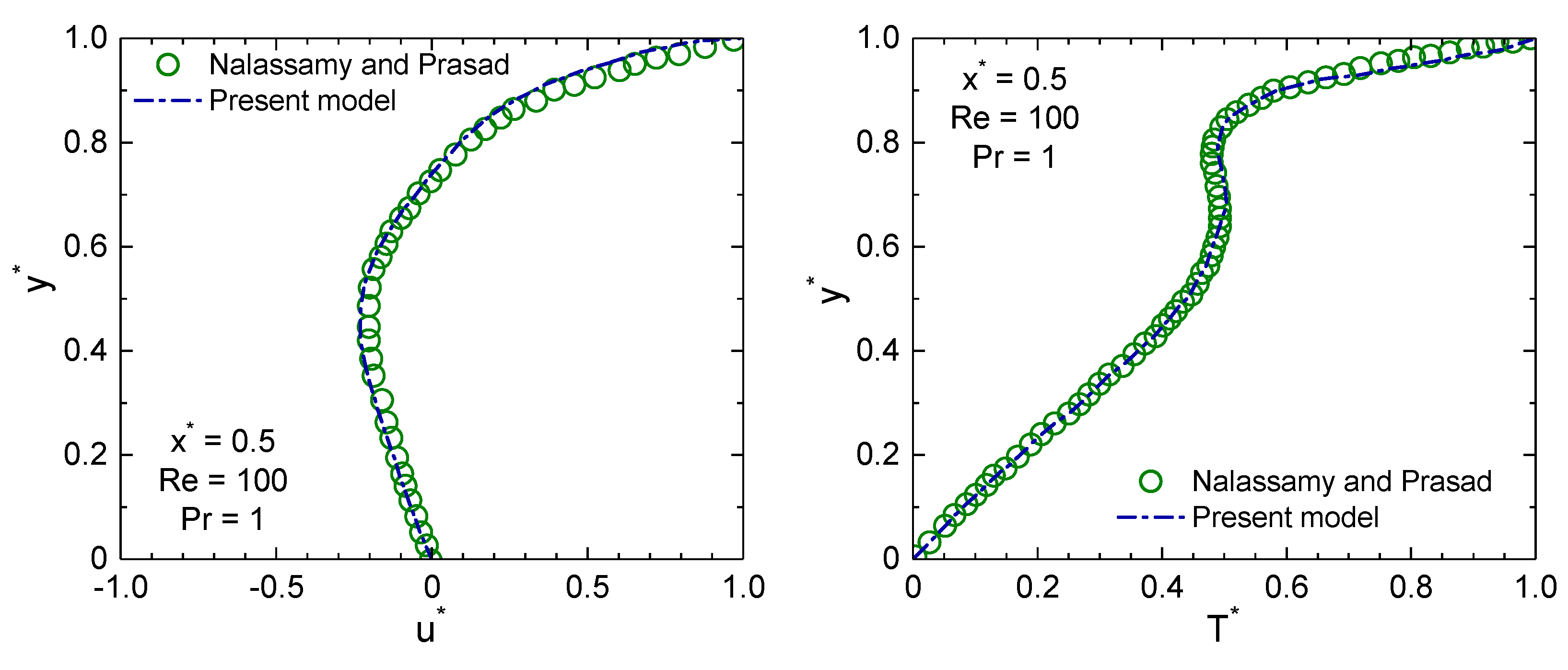
The third test for validation of our numerical method has been performed for a mixed convective scenario using a simplified lid-driven square cavity for comparing velocity and temperature within the cavity. The results of the lid-driven square cavity case are presented in Figure 5. The dimensionless local velocity and temperature profiles at the cavity center (x* = x/L = 0.5) for a mixed convective flow with Re = 100 are shown along with the height of the cavity (y* = y/H). The present model data are compared with the data presented by Nalassamy and Prasad [56]. Both the velocity and temperature profiles of the present model show excellent agreement with the results predicted by Nalassamy and Prasad [56].
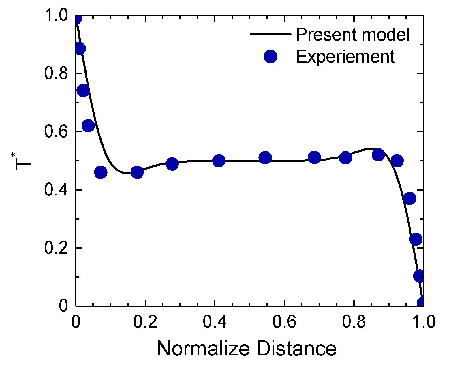
The fourth test for validation of our numerical method has been performed for a square cavity filled with nanofluid that has adiabatic horizontal walls and heated vertical walls. Here, the present model is compared with the experimental data of Ghodsinezhad et al. [57]. The normalized temperature profile along the mid-section of the cavity is shown in Figure 6 for Al2O3–water nanofluid with nanoparticle concentration of 1%. It can be seen that the velocity components of present model slightly deviate from the experimental data near the walls, but the rest of the temperature profile shows a good agreement with the experimental data. Overall, the solutions of present numerical code are in a very good agreement with the experimental data available in open literature. In summary, the validations shown in Table 2 and Figure 4, Figure 5 and Figure 6 for the four cases of experiments and numerical models demonstrate that the results presented in this manuscript are accurate.
4. Results and Discussion
In this section, the numerical results of the mixed convection flow and heat transfer of Al2O3–water nanofluid in a lid-driven square cavity with an intruded rectangular fin are presented. To optimize the fin geometry for maximizing the heat transfer, this study explores the possibilities of varying the strength of buoyancy force (103 ≤ Ra ≤ 107), strength of inertial force (100 ≤ Re ≤ 2000), and mixed convective strength (10−3 ≤ Ri ≤ 102) for various fin aspect ratios (H1/L1), keeping the cavity size and the fin area ratio (φ) fixed. The fin aspect ratio (H1/L1) was varied from 0.1 to 10. In addition, the simulations are performed for various Al2O3 nanoparticles concentrations and two other fin area fractions. Here the Prandtl number of water is 6.83, while the Prandtl numbers of Al2O3–water nanofluids are estimated as 6.59, 6.37, and 5.97 for 1%, 2%, and 4% nanoparticle concentrations, respectively. For all the simulations, the base case parameters are chosen as: Re = 1000, Ra = 105, 1% Al2O3, and φ = 0.05.
4.1. Effect of Fin Shape on Local Heat Transfer
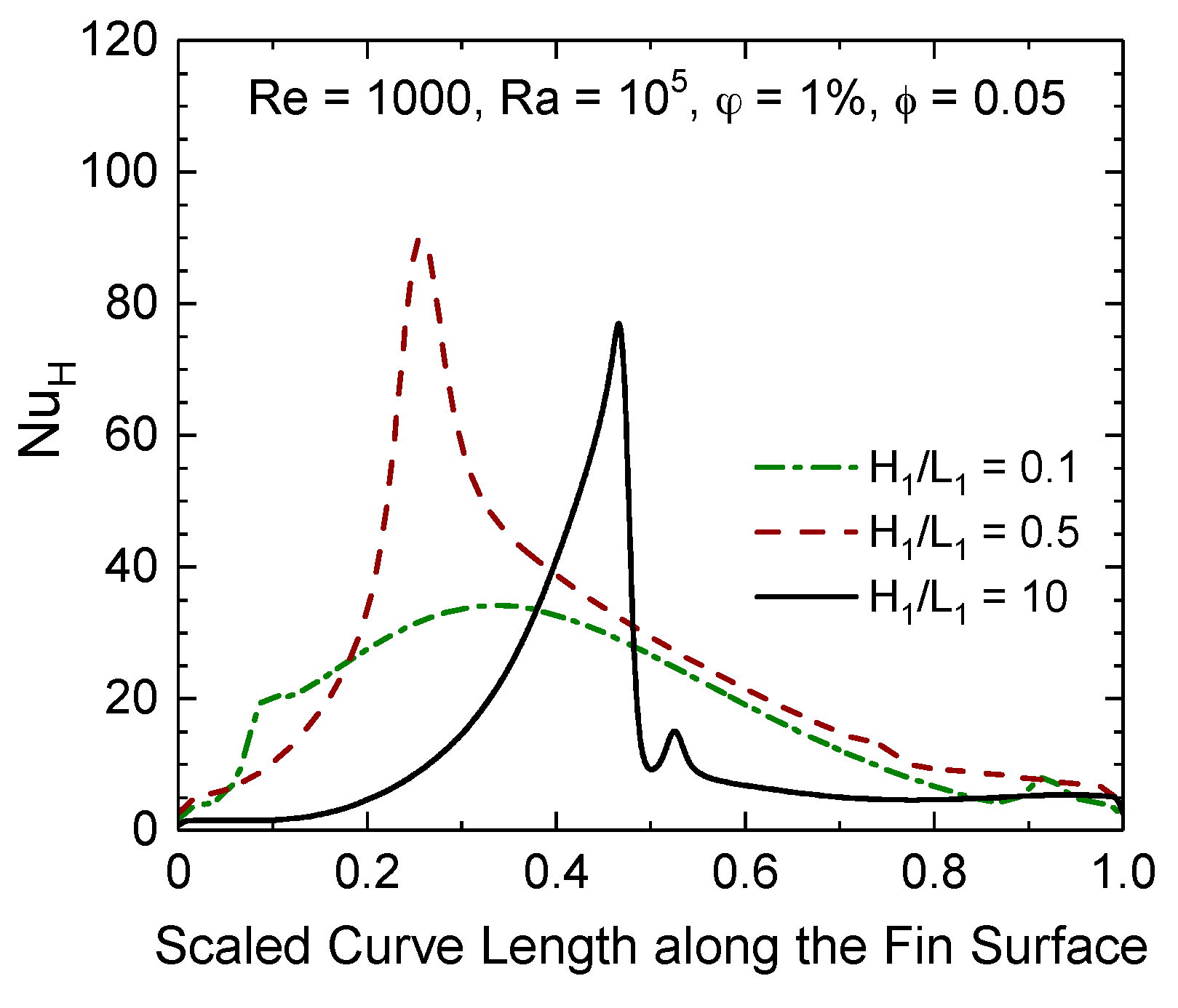
The effect of the fin shape on local heat transfer is analyzed by looking into the local Nusselt number (NuH) profiles and flow and thermal fields for various fin aspect ratios. The local Nusselt number is an important aspect to understand heat transfer of each small element before going into the global heat transfer in the form of average Nusselt numbers. Figure 7 shows the local Nusselt number profiles along the fin surface for different fin aspect ratios for the base case parameters (Re = 1000, Ra = 105, ϕ = 1%, and φ = 0.05). Here the fin surface curve length is scaled with the fin curve length that is exposed inside the cavity (=2H1 + L1).
Figure 7 highlights the location of the fin corners; the first left region represents the left vertical surface of the fin, the middle region represents the fin top surface, and the right section represents the right vertical surface of the fin. Two peaks in each curve of Figure 7 indicate the corners of the rectangular fin and the distance between peaks represents the fin width (L1). The results show that each curve always has a peak, especially large for left-hand side, of local Nusselt number, this phenomenon is considered to be due to the increase of the pressure when going through the corner, which result to have a higher heat transfer near the left-hand peak. This effect is less significant on the right-hand peak as the fluid motion is interfered and blocked by the fin before the fluid reaches the right-hand side, therefore, the increase of heat transfer is considerably less and all local Nusselt numbers are skewed towards the left-hand side. This could be explained by the direction of lid velocity. Since the lid is moving from left to right, fluid motion is downward near the right surface of the fin and the direction of thermal diffusion is upward, which in turns, negate the heat transfer from the fin surface to the surrounding nanofluid. Conversely, fluid motion and the direction of thermal diffusion are upward on the left side of the fin. Thus, heat transfer from the fin surface is higher at the left corner of the fin.
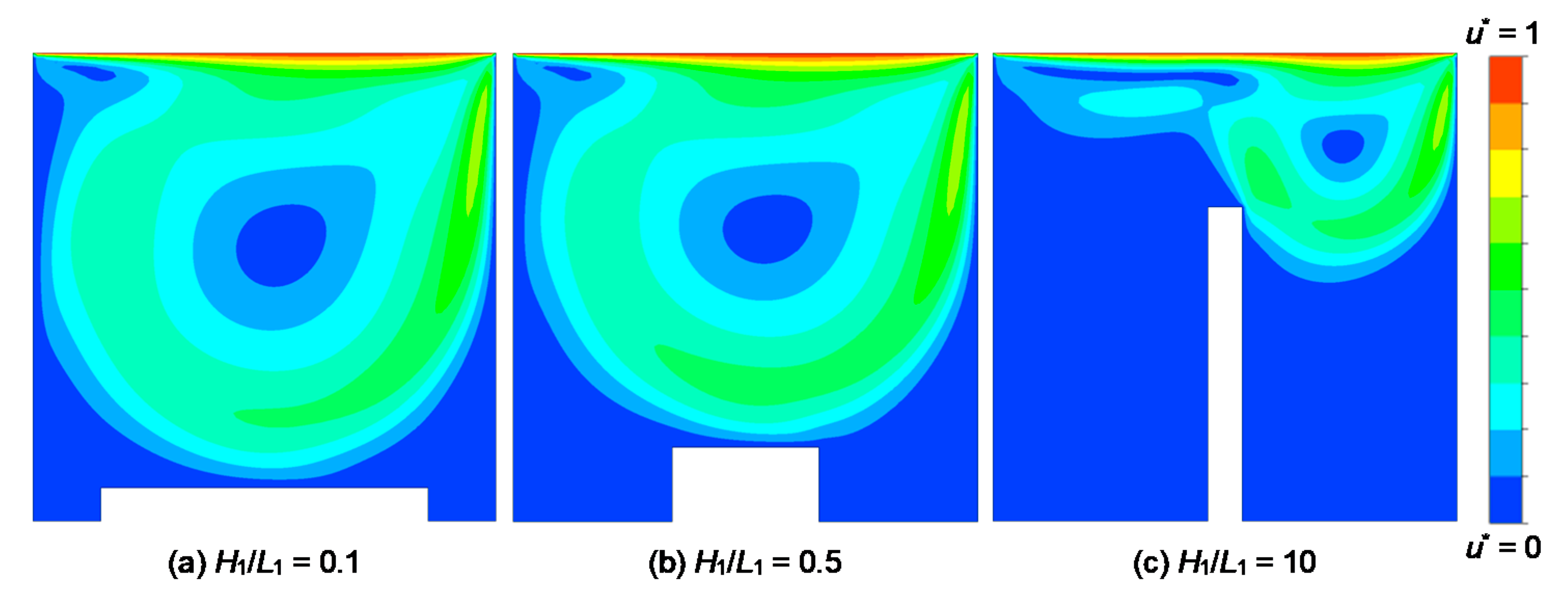
The results shown in Figure 7 can be further analyzed by carefully investigating flow and thermal fields for different fin aspect ratios. The flow and thermal fields are depicted in the forms of scaled velocity contours and isotherms in Figure 8 and Figure 9, respectively. Figure 8 shows the scaled velocity contours for Re = 1000 and Ra = 105 for three aspect ratios, including the lowest (H1/L1 = 0.1) and the highest (H1/L1 = 10). As seen from the contours, the inertial force helps to remove the heat from the surface of the fin. At the lowest aspect ratio (Figure 8a), only a small fraction of fluid over the fin top surface is forced by the external force, while a large amount of fluid is almost stagnant. This indicates that the advection takes place only in the middle section of the fin top surface. As the fin aspect ratio increases (Figure 8b), a better convection takes place over the fin top surface that actually increases the average Nusselt number and provides a better heat transfer. Further increase of the fin aspect ratio (Figure 8c) starts to hinder the flow to penetrate inside the cavity that eventually reduces the thermal energy transport and decreases significantly at the highest aspect ratio. It is noticed that almost two-thirds of nanofluid inside the cavity is stagnant and does not participate in the convective transport.
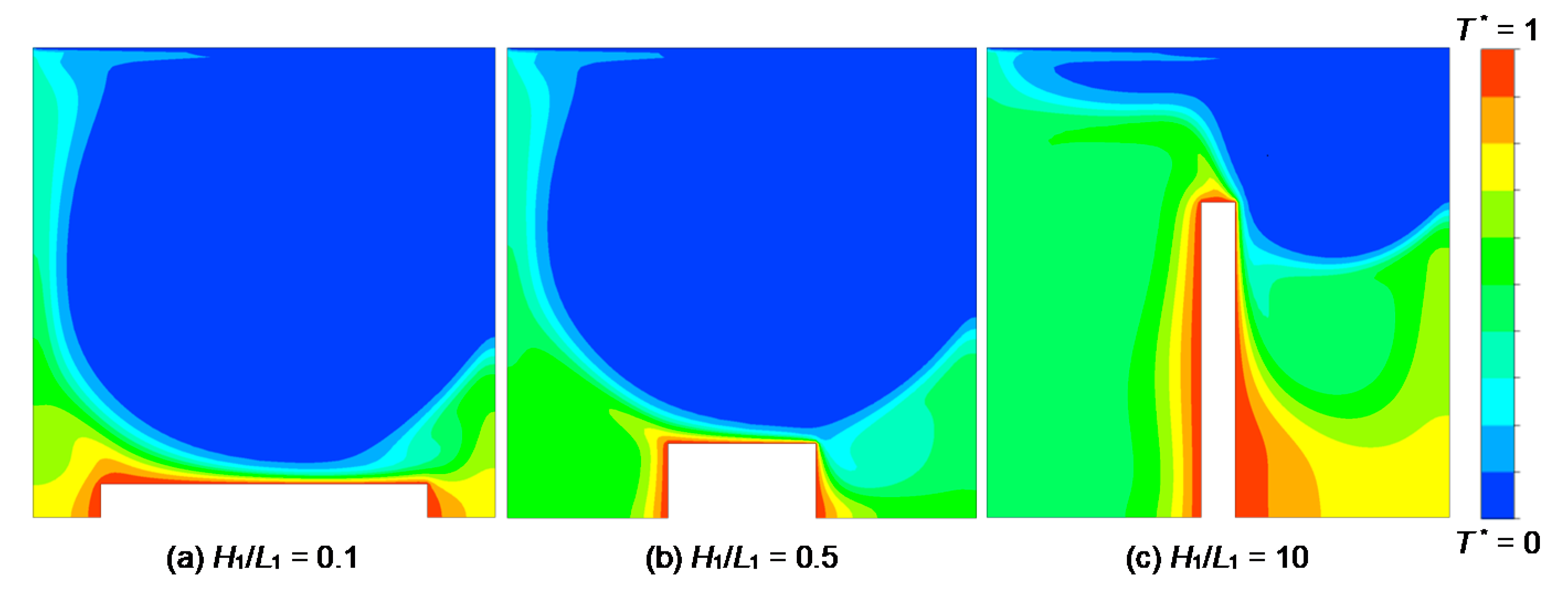
Isotherms corresponding to Figure 8 are shown in Figure 9. One can easily observe that the distribution of temperature is almost homogeneous over the top surface of the fin for the lowest aspect ratio (Figure 9a), while the lateral surfaces of the fin show an augmentation of the temperature magnitude due to stagnant nanofluid. For H1/L1 = 0.5, the nanofluid penetrates in a more intensive way into the region between the fin and the cavity allowing a higher thermal energy transfer from the fin to the surrounding flow. For the higher aspect ratio (H1/L1 = 10), the temperature distribution is poor compared to the lowest aspect ratio and most of the heat is trapped near the two sides of the fin causing an augmentation of the temperature magnitude and reduces thermal energy transfer from the fin to the surrounding flow. Figure 9a further indicates that due to the higher width of the fin, nanofluid does not have active flow on the left and right bottom corner of the cavity, which resulted in the peaks to be smaller in local Nusselt number profile as depicted in Figure 7 for H1/L1 = 0.1. Since the lower temperature stream of the nanofluid flow is directly flowing into the top surface, the temperature gradient is higher on the fin top surface, resulting in a higher local Nusselt number as depicted in Figure 9b. Figure 9c shows that most of the convective heat transfer is dominant on the right fin surface and extremely low on the left surface, which is predominantly thermal diffusion. This is due to the geometrical issue that such a tall fin (H1/L1 = 10) almost completely separates the cavity into two halves. Most of the fluid becomes stagnant on the left side and circulates only in the right-hand part.
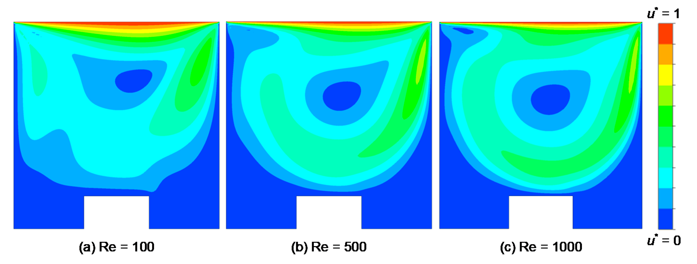
The effect of lid velocity on the local heat transfer is shown in Figure 10. For all aspect ratios, it is observed that the increase in the lid velocity, and thus the Reynolds number, greatly increase the heat transfer due to the higher convective flows. Here, the results are shown in a fixed aspect ratio (H1/L1 = 0.5) for different Reynolds numbers as indicated in the figure legend. It is observed that the local heat transfer from the fin surface to the surrounding nanofluid is almost uniform throughout the fin curve length for low Reynolds numbers. As the Reynolds number increases, the local heat transfer from the upper fin surface increases significantly and a peak has been observed at the left corner of the fin. As discussed in the previous section, this is due to the fluid vortex and better circulation inside the cavity as well as due to the direction of lid velocity. On the right side of the fin, fluid motion and thermal diffusion are acting against each other, while on the left side of the fin they act in the same upward direction. Thus, higher heat transfer occurs at the left corner of the fin. This can be further explained by analyzing the flow and thermal fields for various Reynolds numbers.
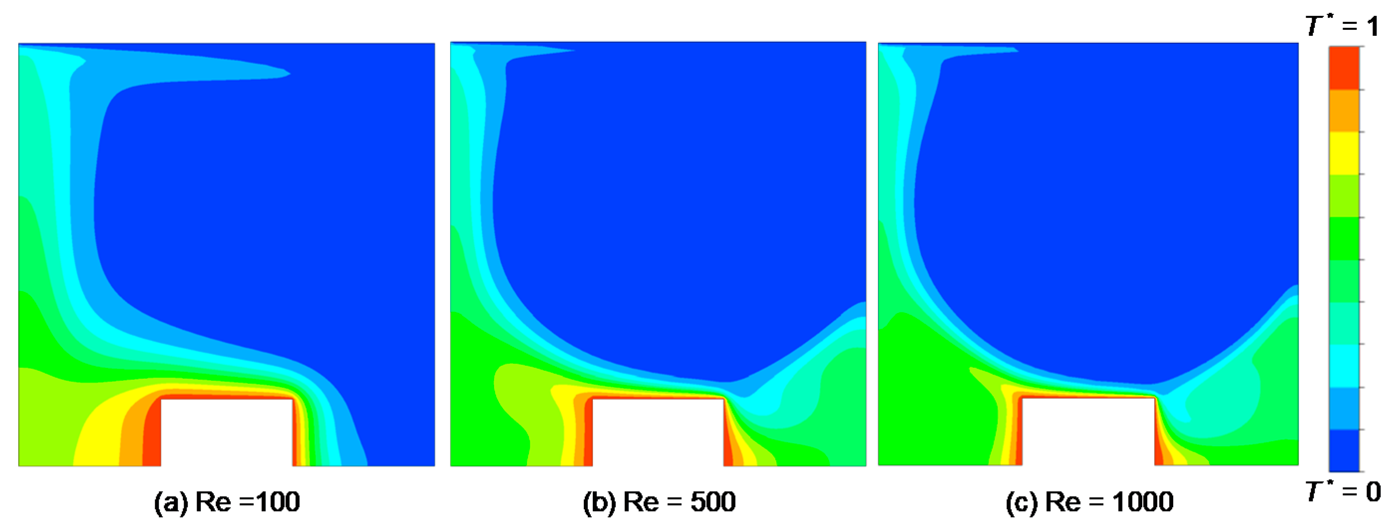
The flow and thermal fields corresponding to Figure 10 are depicted in the forms of scaled velocity contours and isotherms in Figure 11 and Figure 12, respectively, for Re =100, 500, and 1000. Here a diffusive behavior of the flow in the lower region of the cavity is observed at low Reynolds number (Re = 100). Fluid velocity near the top surface of the fin is nearly zero, which indicates that the lid velocity has a negligible effect on the thermal diffusion. As the Reynolds number increases, the magnitude of the local Nusselt number in the left corner of the fin shows the highest value (Figure 10). This indicates that the displacement of hot fluid by the cold fluid from the fin surface by the main vortex generated inside the cavity, as depicted in Figure 11b. The increase in the Reynolds number results in a higher advection of fluid inside the cavity. Thus, there is higher heat transfer from the fin to the surrounding nanofluid. In this case, the convective term in the momentum equation overcomes the diffusion term. Further increase of the Reynolds number (Re = 1000) indicates a complete dominance of fluid motion throughout the cavity. One can easily observe the thermal diffusion at low Reynolds numbers (Figure 12a) and the dominant convection at high Reynolds number (Figure 12c).
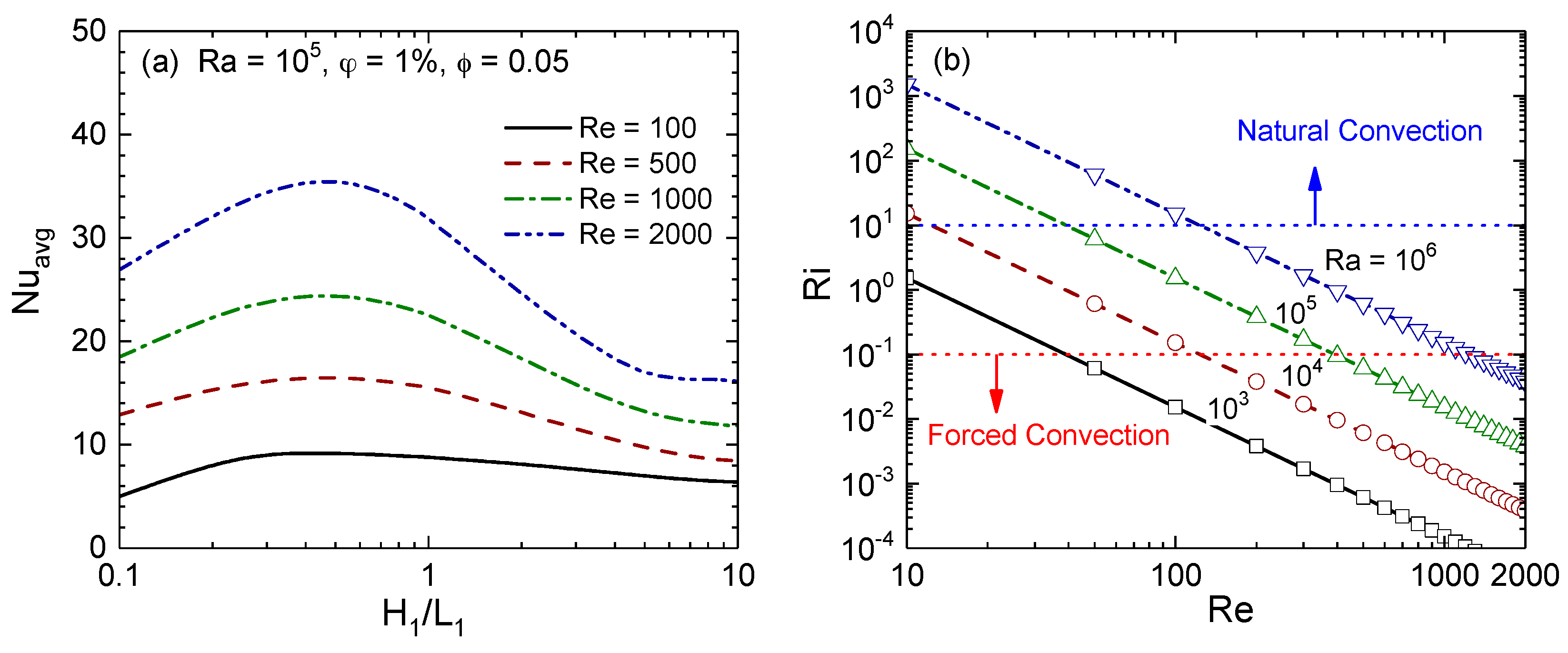
4.2. Effects of Reynolds and Rayleigh Numbers on Average Nusselt Number
The influences of Reynolds numbers on overall heat transfer between the fin and nanofluid are explored by plotting the average Nusselt number (Nuavg) with the fin aspect ratio (H1/L1) for various Reynolds numbers, as shown in Figure 13. Figure 13a indicates that the heat transfer from the fin increases as the fin aspect ratio increases from 0.1 and it reaches a maximum point and then decreases. It is also observed that higher Reynolds numbers provide a higher heat transfer. However, the trend remains the same for all Reynolds numbers, primarily due to the forced convection at Ra = 105, which can be verified by Figure 13b as it shows the forced, mixed, and natural convection regimes as a function of Richardson, Reynolds, and Rayleigh numbers for 1% Al2O3–water nanofluid. As observed in Figure 13b, the heat transfer regime for Ra = 105 and 500 < Re < 2000 is predominantly the forced convection as the Richardson number remains below 0.1. Figure 13a further reveals that the wider fin has a better heat transfer performance than a taller fin for all Reynolds numbers. For instance, at Re = 2000, the highest Nusselt number is observed near the fin aspect ratio of 0.5. At Re = 2000 and H1/L1 = 0.5, the Nuavg is 35.5, which is nearly 31.9% and 120% higher than that obtained for the lowest and highest fin aspect ratios, H1/L1 = 0.1 and H1/L1 = 10, respectively. Clearly, the increase of superficial area does not necessarily lead to an increase of heat transfer rate from the fin to the surrounding nanofluid flow.
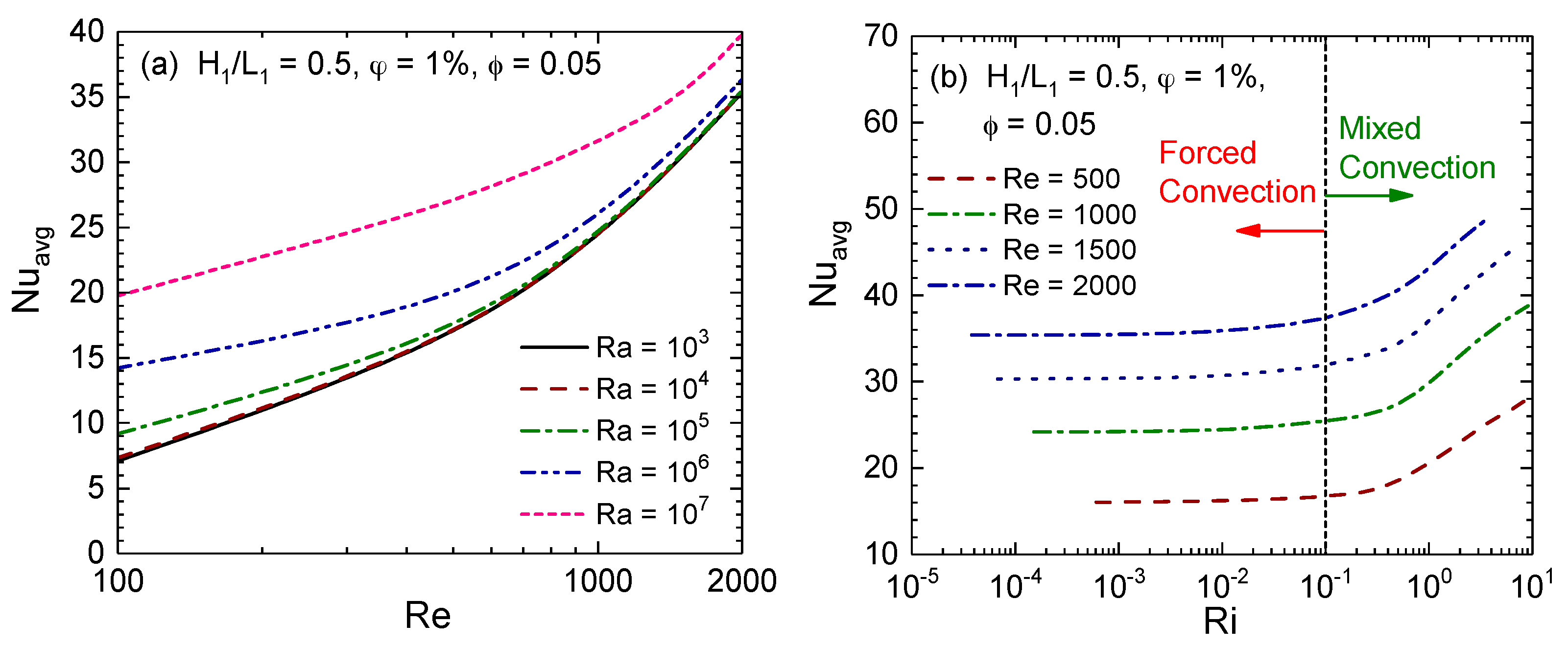
The influences of Rayleigh numbers on overall heat transfer between the fin and nanofluid are explored by plotting Nuavg with Reynolds numbers, as shown in Figure 14. Figure 14a shows the effects of the Rayleigh numbers on the heat transfer between the fin and nanofluid that are analyzed by varying the Rayleigh number from 103 to 107, as indicated in the legend. For low Rayleigh numbers, the effects of buoyancy force on the heat transfer are almost negligible or small for the entire range of Reynolds numbers. For high Rayleigh numbers, the effects are noticeable at low Reynolds number, where the effects of inertial force are small. However, at a high Rayleigh number and Reynolds number, the variations between the average Nusselt numbers with Rayleigh numbers are small compared with the variations observed at low Reynolds numbers. Here, the inertial force is acting against the buoyancy force, which reduces the mixed convective heat transfer. This can be further explained by examining Figure 13b, as it shows that at Re = 1000, changing the Rayleigh number from 103 to 106 does not change the heat transfer regime. In all four cases of Rayleigh number, fluid motion is dominated by the forced convection. Conversely, for low Reynolds number (Re < 500), Nuavg increases with Rayleigh numbers as the fluid motion at high Rayleigh numbers is dominated by the mixed convection (0.1 < Ri < 10). For low Re, one can also increase the Richardson number over 0.1 by increasing Rayleigh number, which will shift the heat transfer regime from the forced convection to the mixed convection, as shown in Figure 14b where Nuavg values are also included for several higher Rayleigh numbers (Ra > 106). As observed, Nuavg increases with Richardson numbers, i.e., with Rayleigh numbers, in the mixed convection regime. Here, heat transfer from the fin sidewalls increases as the buoyancy force increases with the Rayleigh numbers due to the mixed convection. Clearly, the increase of Rayleigh number can also be effective in the maximization of the heat transfer for low Reynolds numbers (Re ≤ 100) due to the buoyancy force dominance flow. When comparing the cases for Ra = 103 to Ra = 105 at Re = 100, the increase in the heat transfer is over 20%, as observed in Figure 14a.
It is worthwhile to mention that the trend observed in Figure 14b is valid only for the square cavity with a reasonably sized fin. For no fin and a fin with a low aspect ratio, we can capture a distinct transition from the forced to mixed convection regime at 0.1 < Ri < 10. This can be shown by plotting Nuavg as a function of the Richardson number for various fin aspect ratios. Figure 15 shows the Nuavg as a function of the Richardson number for three fin aspect ratios and two Reynolds numbers. Figure 15a shows that for all three aspect ratios, Nuavg is constant for Richardson number less than 0.1. As the Richardson number increases from 0.1, Nuavg increases with the Richardson number for H1/L1 ≥ 0.5. For H1/L1 = 0.1, we see a distinct transition zone from the forced to mixed convection regime that starts at about Ri = 0.2 and the transitions end at about Ri = 2. This scenario is observed for all Reynolds numbers for H1/L1 > 0.2. However, the transition zone shifts based on the value of the Reynolds number. As shown in Figure 15b for two Reynolds numbers, the transition from the forced convection regime to mixed convection is clearly visible even at low Reynolds number. For low Reynolds number, the onset of significant effects of buoyancy occurred when Ri reached about 1.2 as compared to the value of 0.2 for Re = 1000 and the transition zone is much smaller.
4.3. Effect of Nanoparticles Concentration
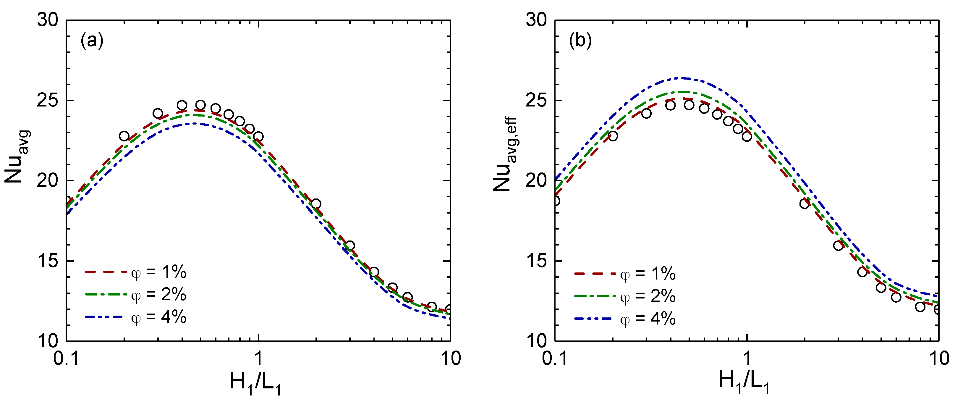
Figure 16 shows the effects of Al2O3-volume fractions on overall heat transfer from the fin surface. Here Figure 16a shows the effects of Al2O3-volume fractions on the average Nusselt number, where different line types are for different Al2O3–water nanofluids and symbols are for pure fluid. It is observed that the addition of nanoparticles in a base fluid reduces the average Nusselt number for all fin sizes. The addition of 1% Al2O3 nanoparticles in water does not show any change in the average Nusselt number. However, 4% Al2O3 nanoparticles show a distinct reduction of the average Nusselt number, particularly near H1/L1 = 0.5. Many studies, however, showed that the addition of nanoparticles in base fluid increases the average Nusselt number when the nanoparticle concentration increases [21,31,32]. We have not seen any such cases; rather we observe a decrease in the average Nusselt number for all the values of Al2O3-volume fractions. Since the nanofluid becomes more viscous with the addition of nanoparticles and reduces the convection current, the temperature gradients near the fin surface reduce as well as the average Nusselt number. Although the average Nusselt number decreases with nanoparticles concentrations, it does not necessarily indicate a reduction of heat transfer. It simply indicates a reduction of convective heat transfer with respect to the conduction heat transfer from the fin to the surrounding nanofluid. It is worthwhile to mention that 4% Al2O3 in water increases the thermal conductivity about 16% than the base fluid. Hence, one can presume about 16% higher conduction from the fin surface to nanofluid. If the change in convective heat transfer is less than 16%, one will get a lower Nusselt number for such cases, as depicted in Figure 16a. If we consider that the conduction between the fin and nanofluid is primarily dominated by the conduction between the base fluid and fin surface and nanoparticles does not influence the conduction heat transfer at the surface of the fin or within the thermal boundary layer, one would then expect a higher average Nusselt number with the higher volume fractions of nanoparticles. This scenario can be depicted by defining the average Nusselt number with respect to the base fluid thermal conductivity, defined as the effective average Nusselt number (Nuavg,eff). Figure 16b depicts the effective average Nusselt number, which is based on base fluid thermal conductivity for various Al2O3-volume fractions. As shown in Figure 16b, the effective average Nusselt number increases with the addition of Al2O3 nanoparticles in water. The higher the nanoparticles volume fractions, the higher the average Nusselt number is. Moreover, results shown in Figure 16 indicate a favorable effect due to the higher thermal conductivity and an unfavorable effect due to higher viscosity. The tradeoffs between these two opposing phenomena may not be beneficial for the mixed convection in cavities. However, the addition of nanoparticles may bring some benefits for the closed- or open-looped cooling/heating systems with the expense of pumping power, as more heat will be conducted from the fin to the surrounding nanofluid due to their higher thermal conductivities.
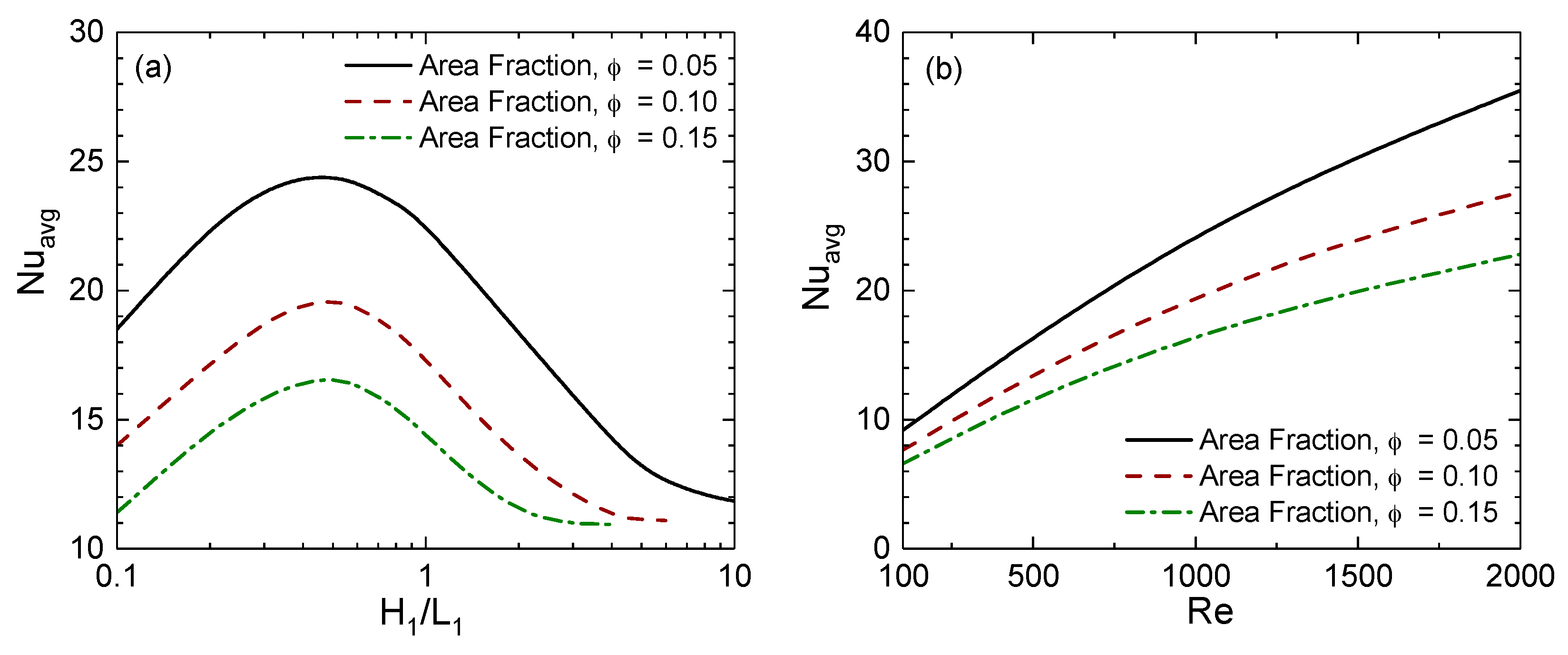
4.4. Effect of Fin Area Fraction
Increasing the size of the fin can be an alternative approach to enhancing the convective heat transfer. Figure 17 shows the effect of the fin area fraction on the average Nusselt number. The results are shown as functions of the fin aspect ratio and Reynolds number for three values of fin area fractions. Increasing the size of the fin also increases the circumferential area of the fin, which enhances the convective heat transfer as the surface area in contact with the fluid is increased. On the other hand, increasing the fin size reduces the space available for fluid to flow through and flow can be blocked by the enlarged fin and may result in a reduction of heat transfer due to the loss of the kinetic energy. As a result, the average Nusselt number significantly reduces as the fin area is increased, as shown in Figure 17a. The reduction is at its maximum at the optimum fin aspect ratio, which is 16% and 33% reduction for φ = 0.10 and 0.15 from φ = 0.05, respectively. At higher fin aspect ratios, H1/L1 = 10, 4, 2 for φ = 0.05, 0.10, 0.15, respectively, the average Nusselt numbers for all three are minimum at similar value, approximately Nuavg = 11. This is considered to be because such a high fin aspect ratio completely blocks the cavity vertically and separate the cavity into two segments, thus all three models can be described as the two separate rectangular cavities with moving the top wall and single high-temperature vertical wall. As shown in Figure 17b, the reduction of heat transfer is more significant at higher Reynolds number. Higher fin area fraction describes the larger object to disturb the flow of the fluid. At low Reynolds number, the flow speed is slower and the flow can smoothly maneuver around the inside feature, thus the increasing object size has less influence. However, at higher Reynolds number, the higher speed of flow can be disturbed significantly, and the flow circulates in a limited area similar to the result obtained for higher fin aspect ratios. Clearly, the size of the fin with respect to the cavity area will have an impact on the overall heat transfer process. At the same time, a larger fin may provide higher heat transfer for a fixed temperature gradient due to the higher surface area when the cavity size is not fixed. However, a larger fin will introduce a larger flow resistance due to the larger area inside the cavity.
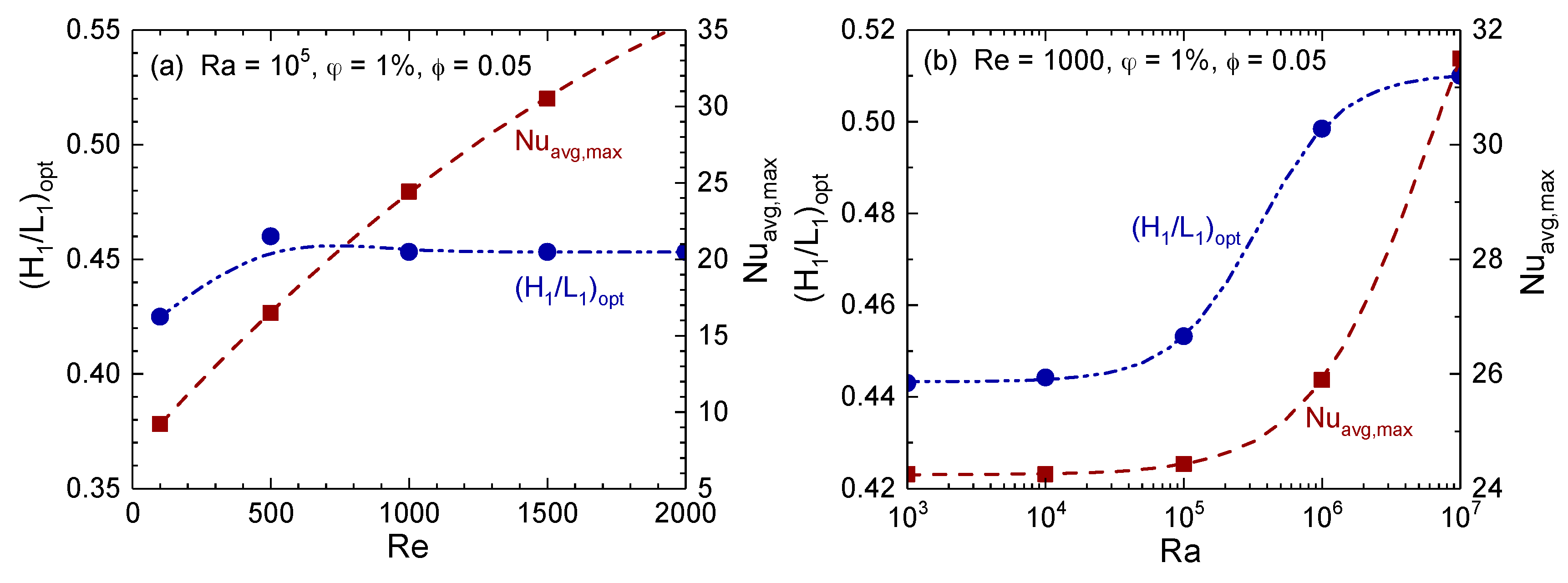
4.5. Optimization of Fin Aspect Ratio
The optimum fin aspect ratio, (H1/L1)opt and corresponding average Nusselt number (denoted as Nuavg,max) as functions of Reynolds and Rayleigh numbers are shown in Figure 18. The optimum fin aspect ratio is the one that maximizes the heat transfer between the fin and nanofluid. No great variation in the optimum fin aspect ratio is observed with Reynolds numbers for the fin area fraction of 0.05 and 1% Al2O3-volume fraction at Ra = 105, as depicted in Figure 18a. The optimum aspect ratio stands approximately at (H1/L1)opt = 0.45 and decreases slightly at low Reynolds numbers. This indicates that a wider fin would be a better choice than a taller fin when inertia force plays a dominant role. The increase of the aspect ratio creates stagnant or no-circulation zones in the corner of the cavity, decreasing the heat transfer between the fin and nanofluid. A taller fin increases the flow resistance and hinders nanofluid circulation inside the cavity. The dimensionless velocity contours for various fin aspect ratios (as shown in Figure 8) indicate the flow circulation as the fin aspect ratio changes from 0.1 to 10. Conversely, a significant variation in the optimum fin aspect ratio is observed with Rayleigh numbers, as presented in Figure 18b. For low Rayleigh number, the optimum fin aspect ratio is almost unchanged as the flow inside the cavity is predominantly the forced convective flow. For higher Rayleigh numbers, the optimum fin aspect ratio increases as the heat transfer process shift toward the mixed convection regime. The higher average Nusselt number indicates the higher convective heat transfer as well. Clearly, Figure 18 indicates that the optimum fin aspect ratio is independent of Rayleigh and Reynolds numbers in the forced convection regime, while it is strongly influenced by Rayleigh and Reynolds numbers in the mixed convection regime.
5. Conclusions
A numerical study has been performed to investigate the mixed convection flow of Al2O3–water nanofluid in a lid-driven square cavity with an intruded rectangular fin, and to optimize the fin geometry for maximizing the heat transfer using the constructal design method. ANSYS-Fluent was used for the numerical simulations. The effects of various aspects of heat transfer were analyzed, such as the Reynolds number, Rayleigh number, Richardson number, aspect fin ratio, fin area ratio, and nanoparticle concentration, in addition, the optimum fin aspect ratio for forced convection is determined. The results suggest that the resistance to the flow caused by the different aspect ratio of the fin has a strong influence on the mixed convective heat transfer inside the cavity. It is concluded that the wider fin has a better heat transfer performance than a taller fin for all Reynolds numbers. For instance, at Re = 2000, the highest Nusselt number is observed near the fin aspect ratio of 0.5. At Re = 2000 and H1/L1 = 0.5, the Nuavg is 35.5, which is nearly 31.9% and 120% higher than that obtained for the lowest and highest fin aspect ratios, H1/L1 = 0.1 and H1/L1 = 10, respectively. Thus, the increase of superficial area does not necessarily lead to an increase of heat transfer rate from the fin to the surrounding nanofluid flow. The present results further reveal that the Reynolds number significantly affects the heat transfer from the fin to the surrounding nanofluid due to better convection current, while the Rayleigh number has less influence on the heat transfer. However, as the buoyancy force increases, heat transfer increases with the Rayleigh number at high Rayleigh numbers. For optimum fin aspect ratio, the Reynolds number shows little influence, while the variations of the Rayleigh number significantly affect the fin’s optimum aspect ratio. For instance, the optimum fin aspect ratio for φ = 0.05 is found to be 0.45 for all Reynolds numbers at Ra = 105, while the optimum fin aspect ratio changes with the Rayleigh number at Re = 1000. Thus, it can be further concluded that the optimum fin aspect ratio is independent of Rayleigh and Reynolds numbers in the forced convection regime, while it is strongly influenced by Rayleigh and Reynolds numbers in the mixed convection regime. These results clearly highlighted the importance of the constructal design method for the optimization of heat transfer for the fin and how the constructal design approach can be employed in improving the thermal performance of a system. Furthermore, the simulation results highlighted the benefit of using nanofluid in the mixed convective case. Moreover, the addition of nanoparticles shows a higher heat transfer (Nuavg,eff) with respect to the base fluid, which may be beneficial for the closed- or open-looped cooling/heating systems at the expense of pumping power, particularly for solar collectors, nuclear reactors, and food processing.
Author Contributions
All authors contributed to this work. R.C., Y.O., and B.S.M. conceived and designed the model and derived all the equations; R.C. and Y.O. performed all the numerical simulations; R.C., Y.O., and P.K.D. analyzed the data and wrote the paper.
Conflicts of Interest
The authors declare no conflict of interest.
References
- Jaluria, Y.; Gupta, S.K. A numerical study of mixed convection flow in enclosures. Int. J. Energy Res. 1983, 7, 201–210. [Google Scholar] [CrossRef]
- Peric, M. Natural-convection in trapezoidal cavities. Numer. Heat Transf. Part A-Appl. 1993, 24, 213–219. [Google Scholar] [CrossRef]
- Mahmud, S.; Das, P.K.; Hyder, N.; Islam, A.K.M.S. Free convection in an enclosure with vertical wavy walls. Int. J. Therm. Sci. 2002, 41, 440–446. [Google Scholar] [CrossRef]
- Mahmud, S.; Das, P.K.; Hyder, N. Laminar natural convection around an isothermal square cylinder at different orientations. Int. Commun. Heat Mass 2002, 29, 993–1003. [Google Scholar] [CrossRef]
- Tasnim, S.H.; Mahmud, S.; Das, P.K. Effect of aspect ratio and eccentricity on heat transfer from a cylinder in a cavity. Int. J. Numer. Methods Heat Fluid Flow 2002, 12, 855–869. [Google Scholar] [CrossRef]
- Das, P.K.; Mahmud, S. Numerical investigation of natural convection inside a wavy enclosure. Int. J. Therm. Sci. 2003, 42, 397–406. [Google Scholar] [CrossRef]
- Das, P.K.; Mahmud, S.; Tasnim, S.H.; Islam, A.K.M.S. Effect of surface waviness and aspect ratio on heat transfer inside a wavy enclosure. Int. J. Numer. Methods Heat Fluid Flow 2003, 13, 1097–1122. [Google Scholar] [CrossRef]
- Sharif, M.A.R.; Mohammad, T.R. Natural convection in cavities with constant flux heating at the bottom wall and isothermal cooling from the sidewalls. Int. J. Therm. Sci. 2005, 44, 865–878. [Google Scholar] [CrossRef]
- Al-Amiri, A.; Khanafer, K.; Bull, J.; Pop, I. Effect of sinusoidal wavy bottom surface on mixed convection heat transfer in a lid-driven cavity. Int. J. Heat Mass Transf. 2007, 50, 1771–1780. [Google Scholar] [CrossRef]
- Guo, G.; Sharif, M.A.R. Mixed convection in rectangular cavities at various aspect ratios with moving isothermal sidewalls and constant flux heat source on the bottom wall. Int. J. Therm. Sci. 2004, 43, 465–475. [Google Scholar] [CrossRef]
- Basak, T.; Roy, S.; Sharma, P.K.; Pop, I. Analysis of mixed convection flows within a square cavity with uniform and non-uniform heating of bottom wall. Int. J. Therm. Sci. 2009, 48, 891–912. [Google Scholar] [CrossRef]
- Sun, X.H.; Yan, H.; Massoudi, M.; Chen, Z.H.; Wu, W.T. Numerical simulation of nanofluid suspensions in a geothermal heat exchanger. Energies 2018, 11, 919. [Google Scholar] [CrossRef]
- Eastman, J.A.; Choi, U.S.; Li, S.; Thompson, L.J.; Lee, S. Enhanced thermal conductivity through the development of nanofluids. Mater. Res. Soc. Symp. Proc. 1997, 457, 3–11. [Google Scholar] [CrossRef]
- Buongiorno, J. Convective transport in nanofluids. J. Heat Transf. 2006, 128, 240–250. [Google Scholar] [CrossRef]
- Das, S.K.; Choi, S.U.S.; Patel, H.E. Heat transfer in nanofluids—A review. Heat Transf. Eng. 2006, 27, 3–19. [Google Scholar] [CrossRef]
- Ghasemi, B.; Aminossadati, S.M. Natural convection heat transfer in an inclined enclosure filled with a water-CuO nanofluid. Numer. Heat Transf. Part A-Appl. 2009, 55, 807–823. [Google Scholar] [CrossRef]
- Khanafer, K.; Vafai, K. A critical synthesis of thermophysical characteristics of nanofluids. Int. J. Heat Mass Transf. 2011, 54, 4410–4428. [Google Scholar] [CrossRef]
- Bouhalleb, M.; Abbassi, H. Numerical investigation of heat transfer by CuO–water nanofluid in rectangular enclosures. Heat Transf. Eng. 2016, 37, 13–23. [Google Scholar] [CrossRef]
- Putra, N.; Roetzel, W.; Das, S.K. Natural convection of nano-fluids. Heat Mass Transf. 2003, 39, 775–784. [Google Scholar] [CrossRef]
- Jou, R.Y.; Tzeng, S.C. Numerical research of nature convective heat transfer enhancement filled with nanofluids in rectangular enclosures. Int. Commun. Heat Mass 2006, 33, 727–736. [Google Scholar] [CrossRef]
- Oztop, H.F.; Abu-Nada, E. Numerical study of natural convection in partially heated rectangular enclosures filled with nanofluids. Int. J. Heat Fluid Flow 2008, 29, 1326–1336. [Google Scholar] [CrossRef]
- Talebi, F.; Mahmoudi, A.H.; Shahi, M. Numerical study of mixed convection flows in a square lid-driven cavity utilizing nanofluid. Int. Commun. Heat Mass 2010, 37, 79–90. [Google Scholar] [CrossRef]
- Nayak, R.K.; Bhattacharyya, S.; Pop, I. Numerical study on mixed convection and entropy generation of a nanofluid in a lid-driven square enclosure. J. Heat Transf. 2016, 138, 012503–012511. [Google Scholar] [CrossRef]
- Khanafer, K.; Vafai, K.; Lightstone, M. Buoyancy-driven heat transfer enhancement in a two-dimensional enclosure utilizing nanofluids. Int. J. Heat Mass Transf. 2003, 46, 3639–3653. [Google Scholar] [CrossRef]
- Ostrach, S. Natural convection in enclosures. Adv. Heat Transf. 1972, 8, 161–227. [Google Scholar]
- Poulikakos, D.; Bejan, A. Natural convection experiments in a triangular enclosure. J. Heat Transf. 1983, 105, 652–655. [Google Scholar] [CrossRef]
- Papanicolaou, E.; Jaluria, Y. Mixed convection from an isolated heat-source in a rectangular enclosure. Numer. Heat Transf. Part A-Appl. 1990, 18, 427–461. [Google Scholar] [CrossRef]
- Nardini, G.; Paroncini, M.; Corvaro, F. Effect of heat transfer on natural convection in a square cavity with two source pairs. Heat Transf. Eng. 2014, 35, 875–886. [Google Scholar] [CrossRef]
- Wang, G.; Meng, X.; Zeng, M.; Ozoe, H.; Wang, Q.W. Natural convection heat transfer of copper-water nanofluid in a square cavity with time-periodic boundary temperature. Heat Transf. Eng. 2014, 35, 630–640. [Google Scholar] [CrossRef]
- Tiwari, R.K.; Das, M.K. Heat transfer augmentation in a two-sided lid-driven differentially heated square cavity utilizing nanofluids. Int. J. Heat Mass Transf. 2007, 50, 2002–2018. [Google Scholar] [CrossRef]
- Chatterjee, D.; Gupta, S.K.; Mondal, B. Mixed convective transport in a lid-driven cavity containing a nanofluid and a rotating circular cylinder at the center. Int. Commun. Heat Mass 2014, 56, 71–78. [Google Scholar] [CrossRef]
- Abu-Nada, E.; Chamkha, A.J. Mixed convection flow of a nanofluid in a lid-driven cavity with a wavy wall. Int. Commun. Heat Mass 2014, 57, 36–47. [Google Scholar] [CrossRef]
- Bejan, A. From heat transfer principles to shape and structure in nature: Constructal theory. J. Heat Transf. 2000, 122, 430–449. [Google Scholar] [CrossRef]
- Lorenzini, G.; Moretti, S. A cfd application to optimize t-shaped fins: Comparisons to the constructal theory’s results. J. Electron. Packag. 2007, 129, 324–327. [Google Scholar] [CrossRef]
- Lorenzini, G.; Medici, M.; Rocha, L.A.O. Convective analysis of constructal t-shaped fins. J. Eng. Thermophys. 2014, 23, 98–104. [Google Scholar] [CrossRef]
- Lorenzini, G.; Machado, B.S.; Isoldi, L.A.; dos Santos, E.D.; Rocha, L.A.O. Constructal design of rectangular fin intruded into mixed convective lid-driven cavity flows. J. Heat Transf. 2016, 138, 102501. [Google Scholar] [CrossRef]
- Li, P.; Xie, Y.H.; Zhang, D.; Xie, G.N. Heat transfer enhancement and entropy generation of nanofluids laminar convection in microchannels with flow control devices. Entropy 2016, 18, 134. [Google Scholar] [CrossRef]
- Ting, H.H.; Hou, S.S. Numerical study of laminar flow and convective heat transfer utilizing nanofluids in equilateral triangular ducts with constant heat flux. Materials 2016, 9, 576. [Google Scholar] [CrossRef] [PubMed]
- Cong, R.; Zhou, X.; Machado, B.D.S.; Das, P.K. Mixed convection flow of nanofluid in a square enclosure with an intruded rectangular fin. AIP Conf. Proc. 2016, 1754, 050017. [Google Scholar]
- Patil, M.S.; Seo, J.H.; Kang, S.J.; Lee, M.Y. Review on synthesis, thermo-physical property, and heat transfer mechanism of nanofluids. Energies 2016, 9, 840. [Google Scholar] [CrossRef]
- Brinkman, H.C. The viscosity of concentrated suspensions and solution. J. Chem. Phys. 1952, 20, 571–581. [Google Scholar] [CrossRef]
- Batchelor, G.K. The effect of Brownian motion on the bulk stress in a suspension of spherical particles. J. Fluid Mech. 1977, 83, 97–117. [Google Scholar] [CrossRef]
- Maxwell-Garnett, J.C. Colours in metal glasses and in metallic films. Philos. Trans. R. Soc. Lond. Ser. A 1904, 203, 385–420. [Google Scholar] [CrossRef]
- Hamilton, R.L.; Crosser, O.K. Thermal conductivity of heterogeneous two-component systems. Ind. Eng. Chem. Fundam. 1962, 1, 187–191. [Google Scholar] [CrossRef]
- Das, P.K.; Li, X.; Liu, Z.S. Effective transport coefficients in PEM fuel cell catalyst and gas diffusion layers: Beyond Bruggeman approximation. Appl. Energy 2010, 87, 2785–2796. [Google Scholar] [CrossRef]
- Das, P.K.; Li, X.; Liu, Z.S. Analytical approach to polymer electrolyte membrane fuel cell performance and optimization. J. Electroanal. Chem. 2007, 604, 72–90. [Google Scholar] [CrossRef]
- Das, P.K.; Li, X.; Xie, Z.; Liu, Z.S. Effects of catalyst layer structure and wettability on liquid water transport in polymer electrolyte membrane fuel cell. Int. J. Energy Res. 2011, 35, 1325–1339. [Google Scholar] [CrossRef]
- Das, P.K.; Weber, A.Z.; Bender, G.; Manak, A.; Bittinat, D.; Herring, A.M.; Ulsh, M. Rapid detection of defects in fuel-cell electrodes using infrared reactive-flow-through technique. J. Power Sour. 2014, 261, 401–411. [Google Scholar] [CrossRef]
- Xing, L.; Das, P.K.; Song, X.G.; Mamlouk, M.; Scott, K. Numerical analysis of the optimum membrane/ionomer water content of PEMFCs: The interaction of Nafion ionomer content and cathode relative humidity. Appl. Energy 2015, 138, 242–257. [Google Scholar] [CrossRef]
- Zenyuk, I.V.; Das, P.K.; Weber, A.Z. Understanding impacts of catalyst-layer thickness on fuel-cell performance via mathematical modeling. J. Electrochem. Soc. 2016, 163, F691–F703. [Google Scholar] [CrossRef]
- Bejan, A.; Lorente, S. Design with constructal theory. Int. J. Eng. Educ. 2006, 22, 140–147. [Google Scholar]
- Bejan, A.; Lorente, S. Natural design with constructal theory. Mech. Eng. 2009, 131, 44–48. [Google Scholar]
- Ansys® Academic Research Mechanical, Release 18.1. Available online: https://www.ansys.com/academic/terms-and-conditions (accessed on 25 March 2018).
- Patankar, S.V. Numerical Heat Transfer and Fluid Flow; Taylor & Francis: Abingdon, UK, 1980. [Google Scholar]
- Davis, G.D. Natural-convection of air in a square cavity—A bench-mark numerical-solution. Int. J. Numer. Methods Fluids 1983, 3, 249–264. [Google Scholar] [CrossRef]
- Nallasamy, M.; Prasad, K.K. On cavity flow at high Reynolds numbers. J. Fluid Mech. 1977, 79, 391–414. [Google Scholar] [CrossRef]
- Ghodsinezhad, H.; Sharifpur, M.; Meyer, J.P. Experimental investigation on cavity flow natural convection of Al2O3–water nanofluids. Int. Commun. Heat Mass 2016, 76, 316–324. [Google Scholar] [CrossRef]
Figure 1.
Schematic diagram of the mixed convective flow domain with an intruded rectangular fin in its bottom center and various boundary conditions for the numerical simulation.
Figure 1.
Schematic diagram of the mixed convective flow domain with an intruded rectangular fin in its bottom center and various boundary conditions for the numerical simulation.

Figure 2.
A flowchart illustrating the fin optimization process by using a combination of constructal design and exhaustive search. Here Nuavg,max is the average Nusselt number at an optimum fin aspect ratio of (H1/L1)opt.
Figure 2.
A flowchart illustrating the fin optimization process by using a combination of constructal design and exhaustive search. Here Nuavg,max is the average Nusselt number at an optimum fin aspect ratio of (H1/L1)opt.

Figure 3.
Convergence of numerical simulation for different mesh densities. (a) mean Nusselt number between hot and cold surfaces; (b) local Nusselt number over the fin surface; and (c) percentage of error for the average Nusselt number for three fin area fractions.
Figure 3.
Convergence of numerical simulation for different mesh densities. (a) mean Nusselt number between hot and cold surfaces; (b) local Nusselt number over the fin surface; and (c) percentage of error for the average Nusselt number for three fin area fractions.

Figure 4.
Schematic diagram of a partially heated rectangular cavity filled with pure fluid and the average Nusselt number (Nuavg) as a function of Rayleigh number (Ra) for a comparison of present model data with published data for a partially heated rectangular cavity filled with pure fluid [21]. Reproduced from Ref. [39], with the permission of AIP Publishing.

Figure 5.
The comparison between dimensionless local velocity (u*) and temperature (T*) at the cavity center (x* = 0.5) along the height of a simplified lid-driven square cavity without the fin with those of Nalassamy and Prasad [56].
Figure 5.
The comparison between dimensionless local velocity (u*) and temperature (T*) at the cavity center (x* = 0.5) along the height of a simplified lid-driven square cavity without the fin with those of Nalassamy and Prasad [56].

Figure 6.
The comparison between present model and experimental data for normalized temperature with normalized distance. The experimental data are taken from Ref. [57].
Figure 6.
The comparison between present model and experimental data for normalized temperature with normalized distance. The experimental data are taken from Ref. [57].

Figure 7.
Variations of local Nusselt numbers with fin aspect ratio for the base case parameters (Re = 1000, Ra = 105, ϕ = 1%, and φ = 0.05).
Figure 7.
Variations of local Nusselt numbers with fin aspect ratio for the base case parameters (Re = 1000, Ra = 105, ϕ = 1%, and φ = 0.05).

Figure 8.
Dimensionless velocity contours for various fin aspect ratios (H1/L1) at Re =1000 and Ra = 105 for the fin area fraction of 0.05 and an Al2O3-volume fraction of 1%. (a) H1/L1 = 0.1; (b) H1/L1 = 0.5; (c) H1/L1 = 10.
Figure 8.
Dimensionless velocity contours for various fin aspect ratios (H1/L1) at Re =1000 and Ra = 105 for the fin area fraction of 0.05 and an Al2O3-volume fraction of 1%. (a) H1/L1 = 0.1; (b) H1/L1 = 0.5; (c) H1/L1 = 10.

Figure 9.
Dimensionless thermal contours for various fin aspect ratios (H1/L1) at Re =1000 and Ra = 105 for the fin area fraction of 0.05 and an Al2O3-volume fraction of 1%. (a) H1/L1 = 0.1; (b) H1/L1 = 0.5; (c) H1/L1 = 10.
Figure 9.
Dimensionless thermal contours for various fin aspect ratios (H1/L1) at Re =1000 and Ra = 105 for the fin area fraction of 0.05 and an Al2O3-volume fraction of 1%. (a) H1/L1 = 0.1; (b) H1/L1 = 0.5; (c) H1/L1 = 10.

Figure 10.
Variations of local Nusselt numbers with Reynolds numbers for a fixed fin aspect ratio (H1/L1 = 0.5).
Figure 10.
Variations of local Nusselt numbers with Reynolds numbers for a fixed fin aspect ratio (H1/L1 = 0.5).

Figure 11.
Dimensionless velocity contours for three different Reynolds number for H1/L1 = 0.5 and Ra = 105 for the fin area fraction of 0.05 and an Al2O3-volume fraction of 1%. (a) Re = 100; (b) Re = 500; (c) Re = 1000.
Figure 11.
Dimensionless velocity contours for three different Reynolds number for H1/L1 = 0.5 and Ra = 105 for the fin area fraction of 0.05 and an Al2O3-volume fraction of 1%. (a) Re = 100; (b) Re = 500; (c) Re = 1000.

Figure 12.
Dimensionless thermal contours for three different Reynolds number for H1/L1 = 0.5 and Ra = 105 for the fin area fraction of 0.05 and an Al2O3-volume fraction of 1%. (a) Re = 100; (b) Re = 500; (c) Re = 1000.
Figure 12.
Dimensionless thermal contours for three different Reynolds number for H1/L1 = 0.5 and Ra = 105 for the fin area fraction of 0.05 and an Al2O3-volume fraction of 1%. (a) Re = 100; (b) Re = 500; (c) Re = 1000.

Figure 13.
(a) Effect of fin aspect ratio (H1/L1) on the average Nusselt number (Nuavg) for various Reynolds numbers and (b) Richardson number as a function of Reynolds number for various Rayleigh numbers for 1% Al2O3–water nanofluid. The variations of Nuavg are depicted for ϕ = 1% and φ = 0.05. Different line types correspond to different Reynolds or Rayleigh numbers as indicated in the legend. Reproduced from Ref. [39], with the permission of AIP Publishing.

Figure 14.
(a) Effect of Reynolds number on the average Nusselt number (Nuavg) for various Rayleigh numbers and (b) effect of Richardson number on Nuavg for various Reynolds numbers. Different line types correspond to different Reynolds or Rayleigh numbers as indicated in the legend.
Figure 14.
(a) Effect of Reynolds number on the average Nusselt number (Nuavg) for various Rayleigh numbers and (b) effect of Richardson number on Nuavg for various Reynolds numbers. Different line types correspond to different Reynolds or Rayleigh numbers as indicated in the legend.

Figure 15.
Effect Richardson number on Nuavg for various fin aspect ratios and Reynolds numbers. The onset of significant effects of buoyancy in part (a) and the transition zones are highlighted with dashed circles in part (b).
Figure 15.
Effect Richardson number on Nuavg for various fin aspect ratios and Reynolds numbers. The onset of significant effects of buoyancy in part (a) and the transition zones are highlighted with dashed circles in part (b).

Figure 16.
Effect of Al2O3-volume fraction on the average Nusselt number. (a) Average Nusselt number based on nanofluid properties (denoted as Nuavg) and (b) effective average Nusselt number based on base fluid conductivity (denoted as Nuavg,eff). The variations of Nuavg and Nuavg,eff are depicted for Re = 1000, Ra = 105, and φ = 0.05. Different line types correspond to different Al2O3-volume fractions as indicated in the legend and symbols are for the base fluid case.

Figure 17.
Effect of fin area fraction on Nuavg as a function of (a) fin aspect ratio and (b) Reynolds number for the base case parameters (Re = 1000, Ra = 105, ϕ = 1%, and φ = 0.05).
Figure 17.
Effect of fin area fraction on Nuavg as a function of (a) fin aspect ratio and (b) Reynolds number for the base case parameters (Re = 1000, Ra = 105, ϕ = 1%, and φ = 0.05).

Figure 18.
Optimum fin dimension ((H1/L1)opt) and corresponding average Nusselt number (Nuavg,max) as a function of (a) Reynolds number and (b) Rayleigh number for ϕ = 1% and φ = 0.05. Symbols are the numerical data points and the lines are the best fit.
Figure 18.
Optimum fin dimension ((H1/L1)opt) and corresponding average Nusselt number (Nuavg,max) as a function of (a) Reynolds number and (b) Rayleigh number for ϕ = 1% and φ = 0.05. Symbols are the numerical data points and the lines are the best fit.


Table 1.
Thermophysical properties of the base fluid and Al2O3 nanoparticles that are used for estimating nanofluid properties.
Table 1.
Thermophysical properties of the base fluid and Al2O3 nanoparticles that are used for estimating nanofluid properties.
| Physical Properties | Base Fluid | Nanoparticles |
|---|---|---|
| cp (J/kg·K) | 4179 | 765 |
| ρ (kg/m3) | 997.10 | 3970 |
| k (W/m·K) | 6.13 × 10⁻¹ | 40 |
| β (1/K) | 2.10 × 10⁻⁴ | 8.5 × 10⁻⁶ |
| μ (kg/m) | 1.002 × 10⁻³ | – |
| Pr | 6.83 | – |
Table 2.
Comparison of results obtained in this study with benchmark data of Davis [55].
Table 2.
Comparison of results obtained in this study with benchmark data of Davis [55].
| Rayleigh Number | Nuavg | Percentage of Error (%) | |
|---|---|---|---|
| Benchmark Data | Present Study | ||
| Ra = 103 | 1.116 | 1.110 | 0.541 |
| Ra = 104 | 2.243 | 2.247 | 0.178 |
| Ra = 105 | 4.519 | 4.537 | 0.397 |
| Ra = 106 | 8.799 | 8.925 | 1.412 |
© 2018 by the authors. Licensee MDPI, Basel, Switzerland. This article is an open access article distributed under the terms and conditions of the Creative Commons Attribution (CC BY) license (http://creativecommons.org/licenses/by/4.0/).
Share and Cite
MDPI and ACS Style
Cong, R.; Ozaki, Y.; Machado, B.S.; Das, P.K. Constructal Design of a Rectangular Fin in a Mixed Convective Confined Environment. Inventions 2018, 3, 27. https://doi.org/10.3390/inventions3020027
AMA Style
Cong R, Ozaki Y, Machado BS, Das PK. Constructal Design of a Rectangular Fin in a Mixed Convective Confined Environment. Inventions. 2018; 3(2):27. https://doi.org/10.3390/inventions3020027
Chicago/Turabian StyleCong, Ran, Yu Ozaki, Bruno S. Machado, and Prodip K. Das. 2018. "Constructal Design of a Rectangular Fin in a Mixed Convective Confined Environment" Inventions 3, no. 2: 27. https://doi.org/10.3390/inventions3020027