Optimization of the Micro Channel Heat Sink by Combing Genetic Algorithm with the Finite Element Method

Institute of Mechatronic System Engineering, National University of Tainan, Tainan, Taiwan
*
Author to whom correspondence should be addressed.
Inventions 2018, 3(2), 32; https://doi.org/10.3390/inventions3020032
Submission received: 26 March 2018
/
Revised: 30 April 2018
/
Accepted: 4 May 2018
/
Published: 22 May 2018
(This article belongs to the Special Issue Heat Transfer and Its Innovative Applications)
Abstract
:The design of a micro multi-channel heat sink to achieve the minimum thermal resistance is the purpose of this study. The numerical package is employed by using the genetic algorithm to process the heat dissipation optimization of the micro multi-channel heat sink (the genetic algorithm employs the numerical package). The variables of this optimal design include channel number, channel aspect ratio and the ratio of channel width to pitch, as well as considering the weight of this micro channel heat sink in the optimal design process. Therefore, this optimization is a multi-objective function design. The results show that the thermal resistance is decreased as 0.144 W/K, and the weight of this micro channel heat sink can be decreased, individually or simultaneously.
1. Introduction
High power systems and high power density components are important and have been widely used in recent years. One of the highest pursuits in the system design process is heat removal. Many cooling components or systems have been proposed for the needs of heat dissipation, such as LHP (loop heat pipe), vapor chamber, metal coating, flow path design and porous heat removal. In addition, the cooling device is also miniaturized for much smaller electronic products.
Various kinds of cooling technology have been developed in recent decades, such as micro channel heat sink, heat pipe, impingement cooling and vapor chamber. Due to the development of the high power density device, the micro channel heat sink is one of the popular cooling methods among most kinds of electronic cooling systems. The micro channel heat sink was first proposed by Tuckerman and Pease [1], which brought a new perspective of electronic development and design. The studies of the channel shape and configuration are the most common types of previous research carried out. Kim and Mudawar compared the heat diffusion effects with different aspect ratios, spacings and Biot numbers under rectangular-, trapezoidal-, diamond- and triangular-shaped cross-sections [2]. The results show that the heat transfer performance can be improved by adjusting the cross-section of the channel. A previous study [3] used the inverse problem to optimize the geometric design of the micro channel heat sink. The optimal channel numbers and aspect ratio of the micro channel heat sink were presented. Wei and Joshi [4] found the optimal parameters of the stacked micro channel heat sink by genetic algorithms. The optimal number of layers for the micro channel heat sink under a constant pumping power of 0.01 W to achieve the maximum heat removal was shown [4]. The heat transfer characteristics of wavy channels have been studied [5,6]. The heat transfer performance of the wavy micro channel was better than the straight one with the same cross-section, but increasing the heat transfer efficiency with a wavy micro channel will also increase the pump power relatively.
In addition, [7] investigated the effects of channel configuration and fluid viscosity on flow distribution. More relevant research of heat transfer and fluid characteristics for working fluids in the micro channel heat sink has been investigated, such as the developing flow and thermal regime [8], convective heat transfer and pressure drop [9], subcooled flow boiling [10] and velocity measurement [11]. The micro channel heat sink with staggered pin fins was presented [12]. The best heat removal and lowest pressure drop were found under the sink pin fins conditions. The multi-parameter optimization of the micro channel heat sink was performed to present the best geometry of the heat sink [13]. Temperature sensors combined with the micro channel heat sink were integrated to be a controlled fluidic system to enhance the flexible heat removal [14]. The issue of radiation coupling with convective flow was considered to design the micro heat exchanger accurately [15].
The advantages of the micro channel heat sink were shown in the previous studies. Part of the studies focused on heat transfer performance under different geometries and working fluids. The optimization designs of the micro channel heat sink also focused on increasing the heat transfer performance with the geometry. In fact, the weight of electronics is important, especially in modern miniaturized electronics. Thus, the multi-objective optimization of system performance and weight of the micro channel heat sink are discussed in this paper. This paper improves the ability of heat dissipation and reduces the weight of the micro channel heat sink by combining the genetic algorithm with the finite element method individually and simultaneously.
Many previous optimal design research works have been published and proposed [16]. This research demonstrates how the application of numerical optimal simulation techniques can be used to search for an effective and robust optimization of an effective micro multi-channel heat sink. The optimal design of a heat sink to obtain minimal resistance is achieved in the present study. The numerical design is developed by combining a direct finite element solver with an optimal method in the genetic algorithm (GA). A finite element analysis model, COMSOL, is used as the subroutine to solve the heat and mass transfer profile associated with the variation in the geometry of the heat sink during an iterative optimal process [17].
2. Governing Equations
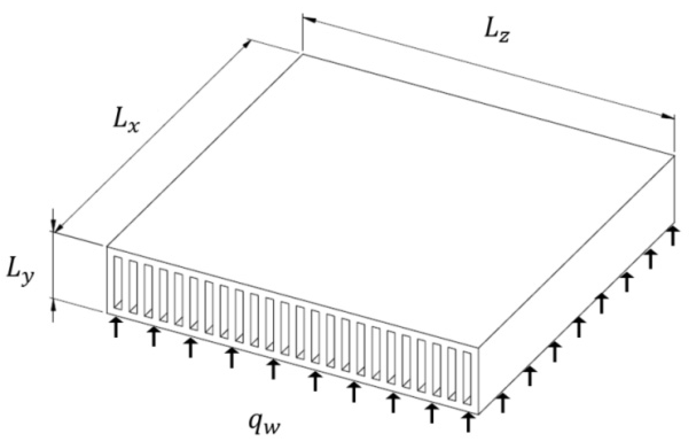
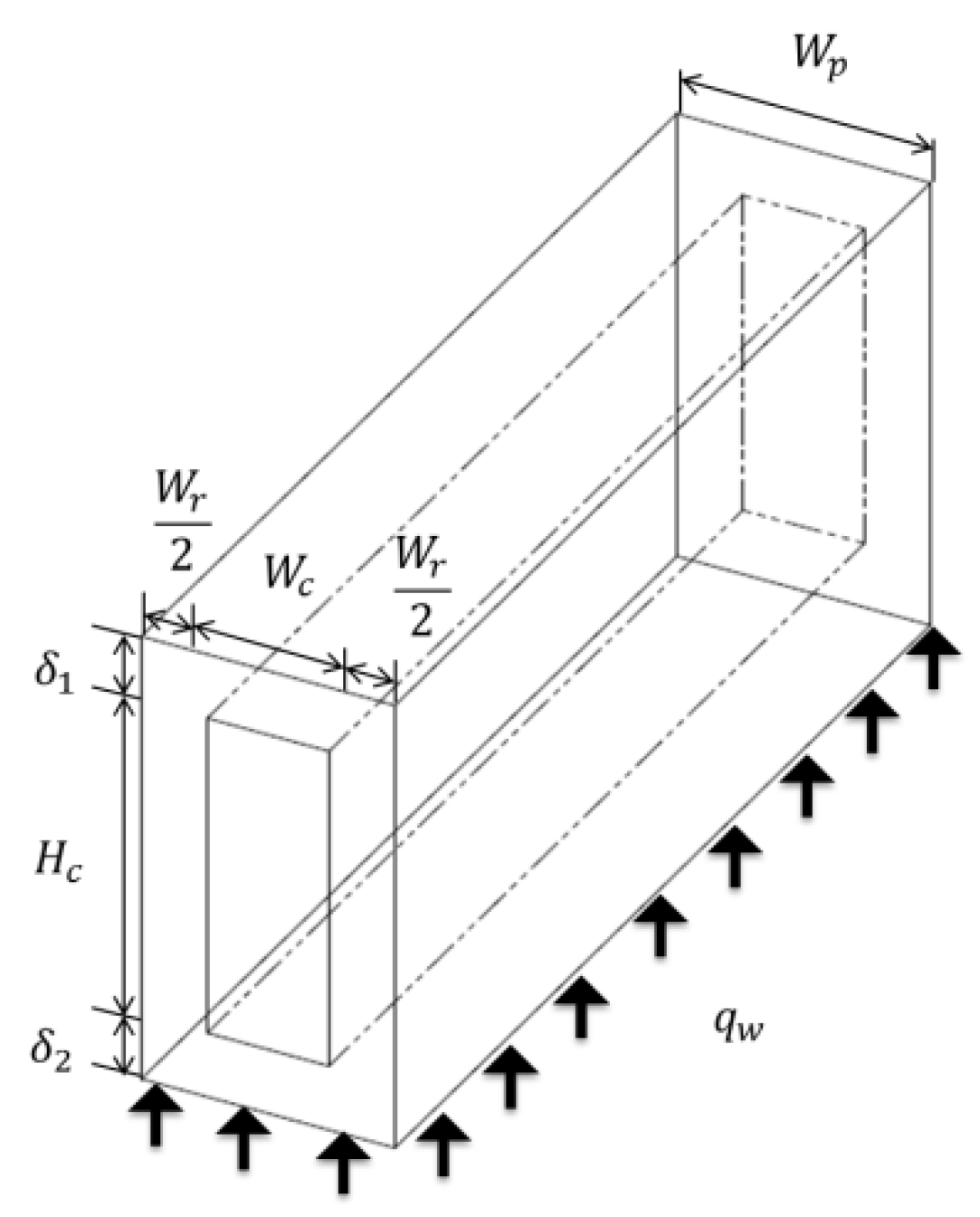
The optimal heat removal design of a micro multi-channel heat sink is performed in this study. This micro multi-channel heat sink was proposed by [3], and the optimization by using the inverse method was discussed. The schematic diagram of the model and symmetric unit of the micro multi-channel heat sink is shown in Figure 1 and Figure 2. The size of this micro multi-channel heat sink is . The natural convection condition is applied on the top surface, and the uniform heat flux is applied on the bottom surface. includes the thickness of the top surface , the thickness of the bottom surface and the height for the flow channel . The width for each symmetric unit is , which includes the flow channel width and the rib width .
The continuity equation and momentum equations in the , , directions of the coolant are:
where , and are the velocity component in the , and directions, and are the density and dynamic viscosity of the coolant and is the coolant pressure.
The energy equation for the coolant is defined as:
where is the coolant temperature, is the specific heat of the coolant and is the thermal conductivity of the coolant.
The energy equation for the solid region is defined as:
where is the solid temperature and is the thermal conductivity of the solid.
The boundary conditions are defined as below:
The inlet boundary and exit are assumed as inlet velocity and outlet pressure.
In addition, the interface between the fluid and wall is defined as:
The inlet velocity of the coolant will be changed with the different cross-sections under the fixed pumping power. The Reynolds number and fanning friction are dependent on the geometric parameters of the channel as follows:
where is the average velocity over the cross-section of the channel and is the hydraulic diameter.
where is the aspect ratio of the channel and is the pressure drop across the channel.
The pumping power of the input coolant is defined as:
where is the total volumetric flow rate and is the cross-sectional area of the channel.
In order to identify the heat dissipative ability of the micro channel heat sink, the thermal resistance is presented and defined as:
where is the bottom surface area of this heat sink.
3. Methods
The variables are designed in this study to minimize the objective function. The variables of this optimization design include the channel number , channel aspect ratio and the ratio of the channel width to pitch . The objective function must be defined in terms of the thermal resistance and the weight of the heat sink, which can be designed to fulfill the design purpose. Different combinations of these coefficients represent different designs of the heat sink where optimization may be found.
In the present study, a single and a multi-objective function are defined as follows:
In this manner, as the objective function is approaching its minimum value in the optimization process, with the definition of , the heat dissipation reaches a maximum value under the minimum heat sink. This implies that the density of heat removal will be increased.
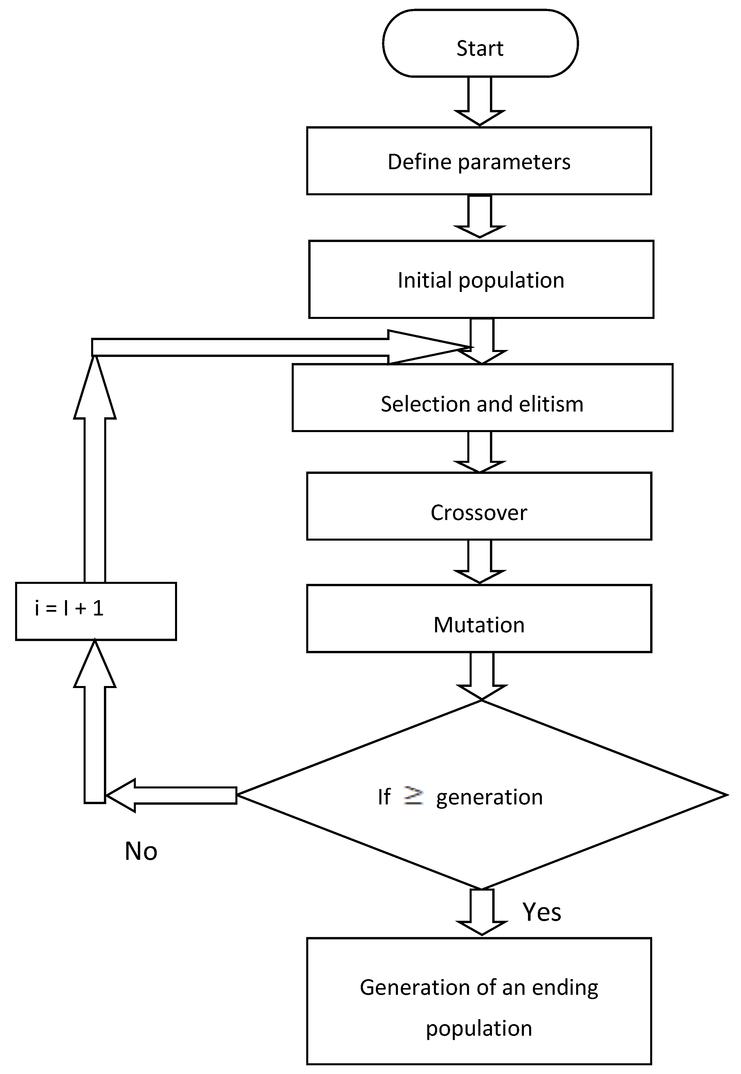
The minimization of the objective function is accomplished by using the GA method. The method searches the fitness of the objective function under the generation of genetic variations. The genetic algorithm is a powerful optimization technique based on natural selection by mimicking the concept of survival of the fittest. Here, the genetic algorithm uses four elements: the encoding structure of the individual, operators to affect individuals (mutation, crossover), a fitness criterion to determine the goodness of each individual (fit) and a selection function (selection). The flowchart of the genetic algorithm is shown in Figure 3.
- (1)
- Generation of an initial population: The initial population is usually chosen randomly. These initial guesses are held as binary encoding of the true variable in which a binary representation is needed to describe each individual in the population of interest, although an increasing number of genetic algorithms use real valued encoding or encoding that has been chosen to mimic, in some manner, the natural data structure of the problems.
- (2)
- Calculation of the fitness for each individual: A fitness function needs to be defined in order to evaluate each individual. Once this is done, a fitness value is assigned to each individual reflecting its quality.
- (3)
- Selection and elitism: Selection is the method of choosing individuals from the population to be parents for the succeeding generation. Elitism is associated with the selection step that copies or preserves the best individual of each generation to prevent losing the best qualities.
- (4)
- Crossover: In this work, single point crossover is used to generate children from two parents by combining the information extracted from parents. The crossover probability is taken as 0.6 by random selection.
- (5)
- Mutation: The purpose of mutation is to provide new, random bits of information during the genetic search and to keep the genetic algorithm from converging too fast before sampling the entire cost surface. With each new generation the whole population is swept, with every bit position in every string visited, and occasionally, a 1 is flipped to a 0 or vice versa with a mutation probability of 0.01.
The self-developed optimizer and the commercial COMSOL code are connected through an interface program COMSOL script. The changes of the undetermined coefficients suggested by the optimizer are sent to the direct problem solver to build the updated geometrical model and to generate the grid system for computation. Next, the direct problem solver is executed based on the updated information to yield the numerical predictions of the temperature fields and the objective function as well, which are further transferred back to the optimizer to calculate the consecutive searching directions.
4. Results
4.1. Comparison with the Inverse Method
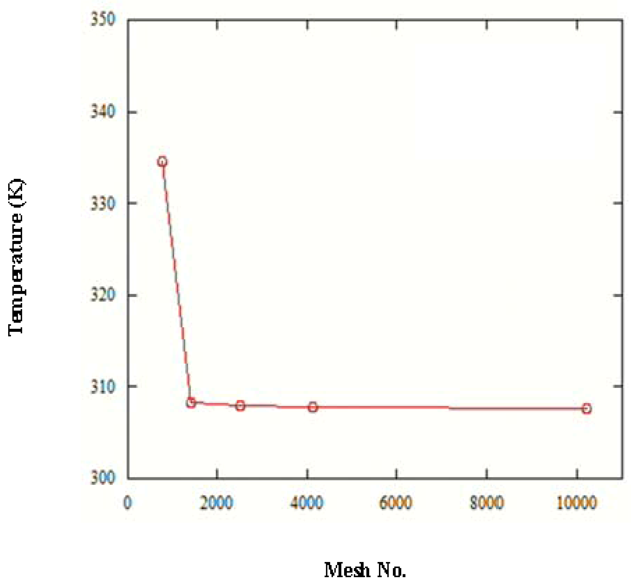
The design of the micro multi-channel heat sink to achieve the minimum thermal resistance is the purpose of this study. The variables of this optimal design include the channel number, channel aspect ratio and the ratio of the channel width to pitch, as well as considering the weight of this micro channel heat sink in the optimal design process. The dimensions of micro multi-channel heat sink are length , width and height . The thickness of the bottom surface is fixed as 100 , and the thickness of the top surface is equal to or greater than 100 . A uniform heat flux is applied on the bottom surface. The pumping power is considered as 0.05 . The materials of the heat sink and coolant are assumed as silicon and water, shown in Table 1. The model of COMSOL is examined based on the optimal mesh test, as shown in Figure 4. The validation of this model is examined with [3]. The thermal resistance of this model is compared with the one of [3] and shown in Table 2. The difference is from 2% to 3.5% as the channel number is from 50 to 71. In addition, the thermal resistance is slightly greater than the one of [3]. This shows that the present model is reliable for discussing the capability of heat removal.
4.2. Sensitivity Analysis
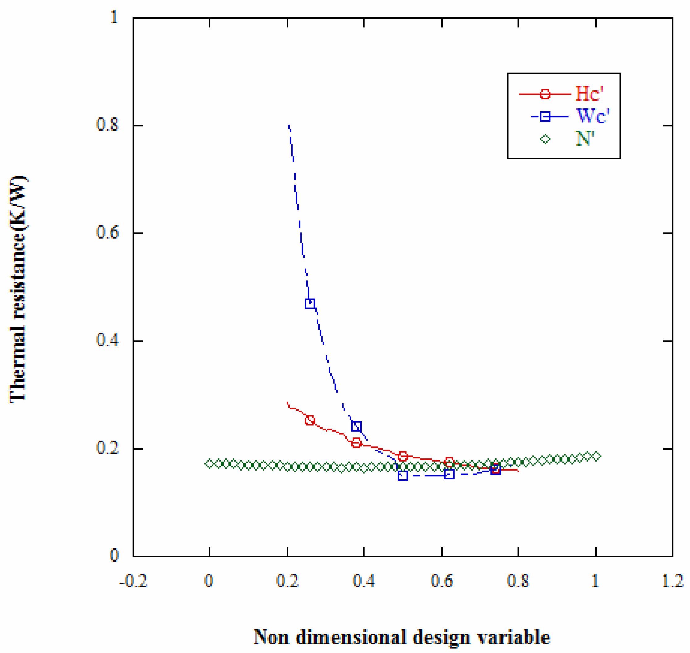
Figure 5 shows the sensitivity analyses of the non-dimensional design variables for the micro channel heat sink.
Here, the non-dimensional design variables are defined as:
The range of sensitivity analysis is N: 50~100; : 20%~80%; : 140 ~560 .
The phenomena are led by the width of the channel, as shown in Figure 5. The thermal resistance decreases from 0.8 to 0.2 as the width increases from 20% to 80%. This illustrates the heat removal dominated by the mass flow rate. The optimal thermal resistance occurs on the width 50% as the suitable velocity and mass flow rate are considered. Then, the thermal resistance decreases as the height of the channel increases. The channel number affects the thermal-fluid phenomena slightly among these parameters.
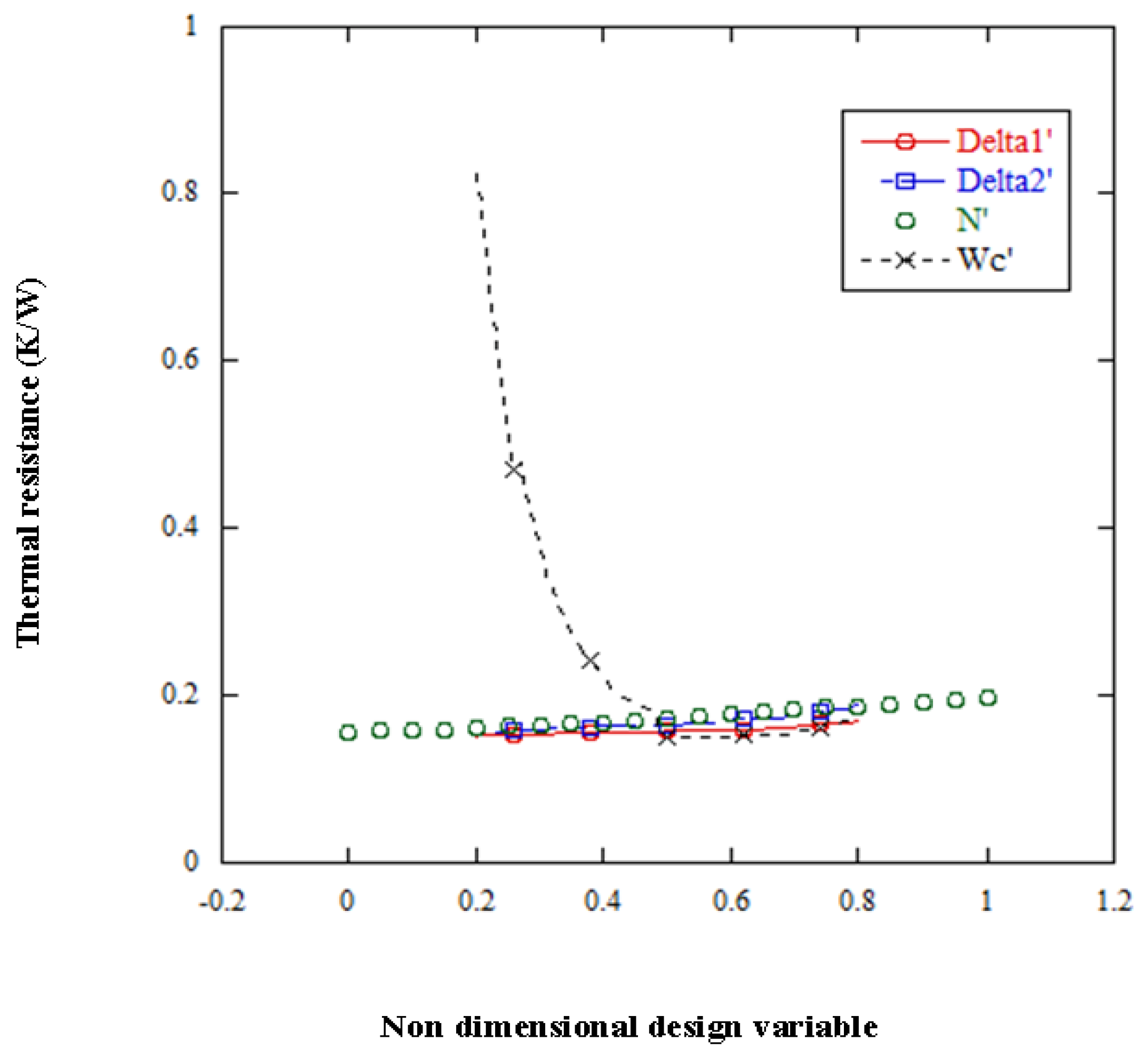
Furthermore, the plate thickness is considered with the fixed width at 50%. The sensitivity analysis is shown in Figure 6. The initial thickness of the bottom plate and top plate is defined as 100 . The height is varied from 730 to 520 as the range of and is 70 . In Figure 4, the thermal resistance increases from 0.1550 0.1967 as the channel number is from 50 to 100. The effects of and are similar from the results in Figure 6. The major effect is caused by the width. The optimal design will be discussed under the different multi-parameter conditions.
4.3. Optimal Study
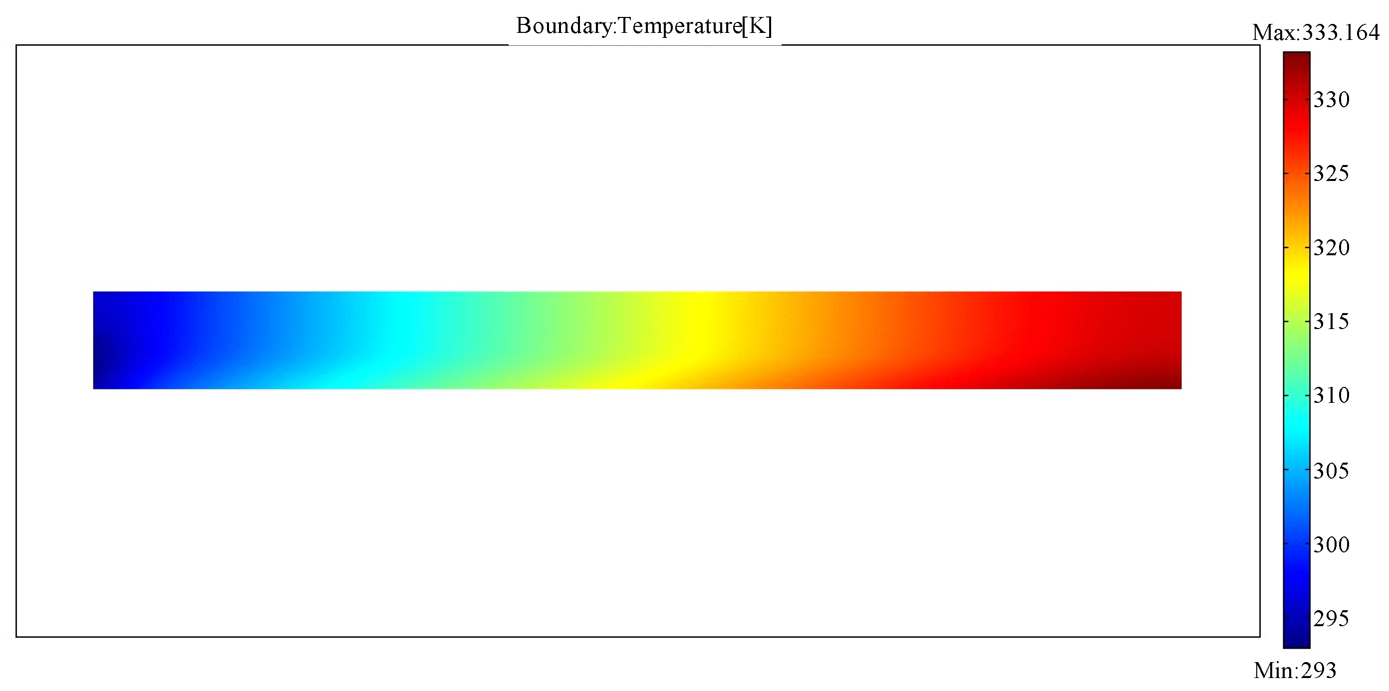
Case 1: The initial channel number is 56, and the aspect ratio () is 4.8, while () is 0.4. The temperature profile of the initial model is shown in Figure 7. The thermal resistance is 0.402 as the minimum and maximum temperatures of the working fluid are 293 K and 333 K.
The side constraints of these variables in the optimal design of Case 1 are shown as:
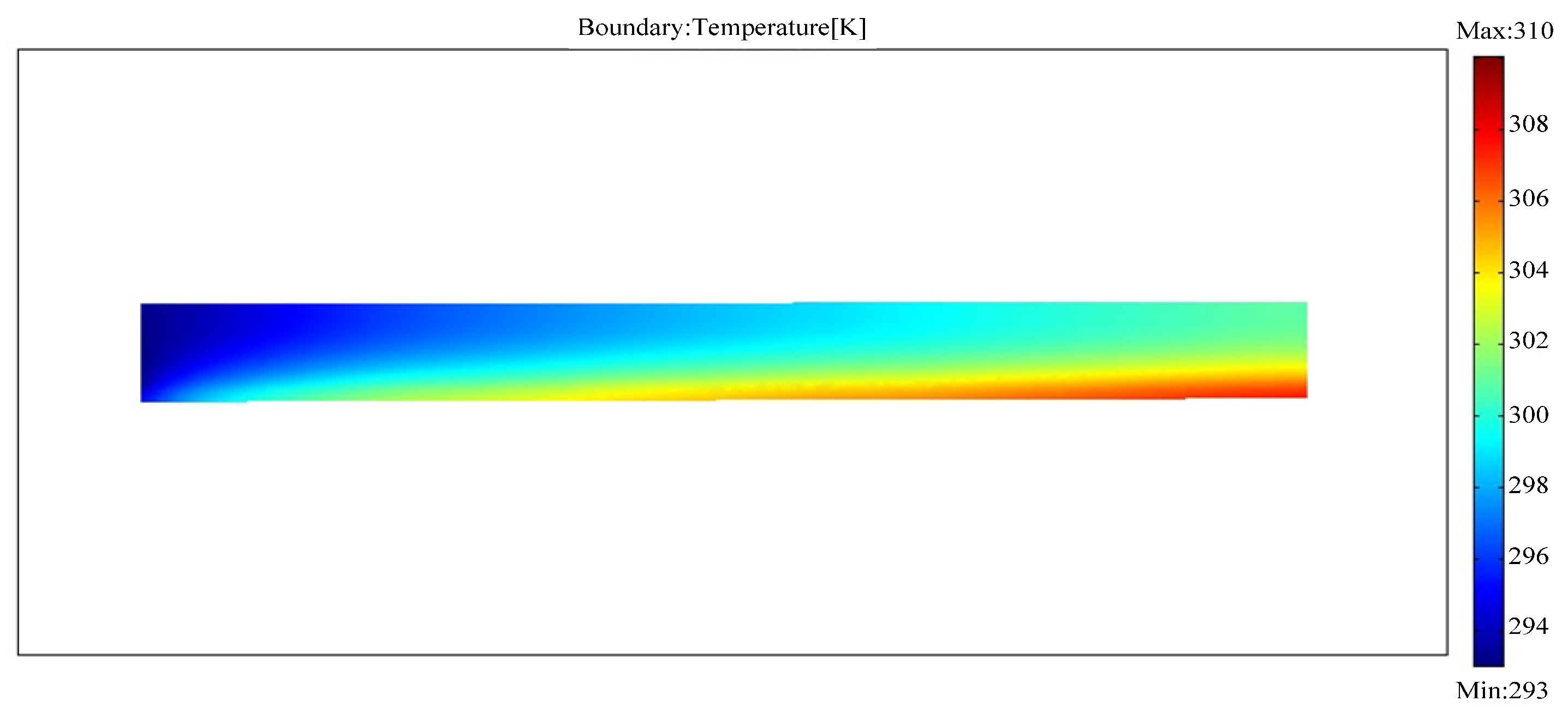
First, the heat dissipative ability of the micro channel heat sink is considered independently. Figure 8 shows the results of the micro channel heat sink with different channel numbers. There are several data that are close and that reach the minimum value. Table 3 shows the optimal results and the optimal design parameters of this case as the channel number is 60, 62, 70 and 74. To compare the results between the channel number is 60 and the initial case, the thermal resistance decreases 0.253 –0.149 . The maximum temperature of working fluid decreases from 333 K to 307.90 K. The temperature of this optimal model is shown in Figure 9. Comparing with Figure 7, the temperature decrease is apparent. The cross-sectional area of the channel of the initial design is smaller than the one of the optimal design. The parameters of = 6.3 and are different from the initial model ( 4.8 and 0.4). From Figure 7 and Figure 9, the temperature of the working fluid increases to 320 K at the one third flow path, but the temperature is lower than 300 K in the optimal design.
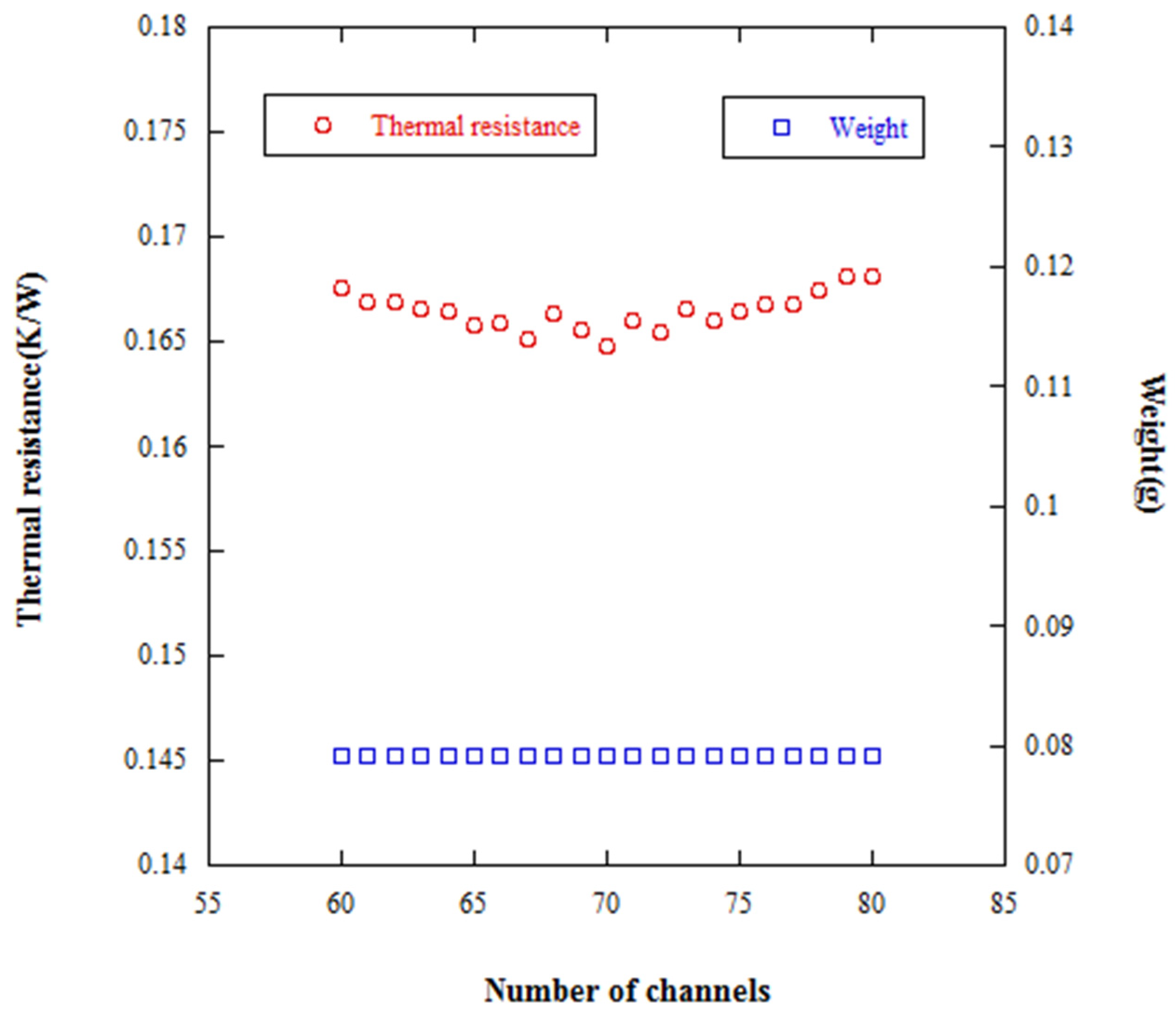
In Case 1, the single objective optimal function is defined as the minimum thermal resistance. The weight of the heat sink is found in the range of 0.1~0.12 g, as shown in Figure 8. However, the weight can be minimized to 0.08 g as the optimal objective function is re-defined as the minimum weight. The results can be observed in Figure 10. The thermal resistance is obtained in the range of 0.165–0.17 . In the microelectronics age, the system weight is relatively important. Figure 10 shows the thermal resistances with the minimum weight with different channel numbers. Comparing with Figure 8, the heat dissipative ability in Figure 8 is better than that in Figure 10, but all the weights in Figure 10 are much smaller. The relation between thermal resistance and weight shows that these two factors are necessary to consider in the multi-objective optimal design. Therefore, the optimal design and the minimization of thermal resistance and weight for the micro channel heat sink are to be processed simultaneously.
In Case 2, the parameter is defined as a variable. The objective function is the minimum thermal resistance. The optimal results of different channel numbers (54, 55, 61, 63) are listed in Table 4. The maximum temperature of the working fluid is slightly lower than Case 1 with the same objective function. However, the thermal resistance in Case 2 under a channel number of 55 decreases almost 3.4% compared to Case 1. The parameter of this case increases to 7.11, and the channel number is not higher for better performance.
Lastly, the multi-objective function is considered. The minimum thermal and weight are reached simultaneously. The optimal results of Case 1 with the single and multi-objective function are listed in Table 5. The channel number of the optimal Case 1 with the multi-objective function is 53 and 60, respectively. The highest temperature is 309.45 and 309.66 K. This is about 1.6 K higher than the results of the single objective function. Actually, the thermal resistance with the multi-objective function increases about 9% compared to the one with the single objective function, but the weight decreases by about 50%. This is an excellent design from the global product point of view.
The optimal results of Case 2 with the single and multi-objective function are listed in Table 6. The channel number of the optimal Case 2 with the multi-objective function is 77 and 79, respectively. In Case 2, the different weighting ratios of are for the cost consideration. The weighting ratio is assumed as one in Table 5. Here, we discuss the effects with the different weighting ratios (one and 1.5) in Table 6. The thermal resistance with the multi-objective function in Case 2 is lower than the one in Case 1, but the weight of heat sink is not. Throughout Table 6, the thermal resistance in Case 2 decreases about 5% compared with the one in Case 1, and the weight increases from 0.08 g to 0.177 g as the weighting ratio is one. As the weighting ratio is changed to 1.5, the weight of the heat sink can be decreased to 0.163 g.
For the purpose of heat sink application, there is better performance for weight reducing in Case 1 and for heat removal in Case 2.
5. Conclusions
The optimal design of the micro channel heat sink combing the finite element method with the genetic algorithm has been performed in this paper. The channel number, channel aspect ratio and the ratio of channel width to pitch were selected as the design variables. The design objectives include the minimization of the thermal resistance and weight of the micro channel heat sink, respectively and simultaneously. The related effects of design variables and thermal performance were investigated. For the purpose of heat sink application, there is better performance for weight reducing in the case with a fixed thickness of the bottom surface. However, excellent heat removal performance can be achieved when both sides of the surface are assumed as design variables. The optimal objective functions and design variables can be planned under the requirements of cost and performance flexibility and effectiveness.
Author Contributions
D.T.W.L. and C.-H.K. conceived of and designed the experiments. C.-H.K. and S.-C.C. performed the simulations. D.T.W.L. and C.-H.K. analyzed the data. D.T.W.L. wrote the paper.
Conflicts of Interest
The authors declare no conflict of interest.
References
- Tuckerman, D.B.; Pease, R.F.W. High-performance heat sinking for VLSI. IEEE Electron Device Lett. 1981, 2, 126–129. [Google Scholar] [CrossRef]
- Husain, A.; Kim, K.Y. Shape optimization of micro-channel heat sink for micro-electronic cooling. IEEE Trans. Compon. Packag. Technol. 2008, 31, 322–330. [Google Scholar] [CrossRef]
- Wang, Z.H.; Wang, X.D.; Yan, W.M.; Duan, Y.Y.; Lee, D.J.; Xu, J.L. Multi-parameters optimization for microchannel heat sink using inverse problem method. Int. J. Heat Mass Transf. 2011, 54, 2811–2819. [Google Scholar] [CrossRef]
- Wei, X.; Joshi, Y. Optimization study of stacked micro-channel heat sinks for micro-electronic cooling. IEEE Trans. Compon. Packag. Technol. 2003, 26, 55–61. [Google Scholar]
- Heidary, H.; Kerman, M.J. Effect of nano-particles on forced convection in sinusoidal-wall channel. Int. Commun. Heat Mass Transf. 2010, 37, 1520–1527. [Google Scholar] [CrossRef]
- Sui, Y.; Teo, C.J.; Lee, P.S.; Chew, Y.T.; Shu, C. Fluid flow and heat transfer in wavy microchannels. Int. J. Heat Mass Transf. 2010, 53, 2760–2772. [Google Scholar] [CrossRef]
- Kumaraguruparan, G.; Kumaran, R.M.; Sornakumar, T.; Sundararajan, T. A numerical and experimental investigation of flow maldistribution in a micro-channel heat sink. Int. Commun. Heat Mass Transf. 2011, 38, 1349–1353. [Google Scholar] [CrossRef]
- Mishan, Y.; Mosyak, A.; Pogrebnyak, E.; Hetsroni, G. Effect of developing flow and thermal regime on momentum and heat transfer in micro-scale heat sink. Int. J. Heat Mass Transf. 2007, 50, 3100–3114. [Google Scholar] [CrossRef]
- Naphon, P.; Khonseur, O. Study on the convective heat transfer and pressure drop in the micro-channel heat sink. Int. Commun. Heat Mass Transf. 2009, 36, 39–44. [Google Scholar] [CrossRef]
- Lee, J.; Mudawar, I. Critical heat flux for subcooled flow boiling in micro-channel heat sinks. Int. J. Heat Mass Transf. 2009, 52, 3341–3352. [Google Scholar] [CrossRef]
- Jones, B.J.; Lee, P.S.; Garimella, S.V. Infrared micro-particle image velocimetry measurements and predictions of flow distribution in a microchannel heat sink. Int. J. Heat Mass Transf. 2008, 51, 1877–1887. [Google Scholar] [CrossRef]
- Yang, D.; Jin, Z.; Wang, Y.; Ding, G.; Wang, G. Heat removal capacity of laminar coolant flow in a micro channel heat sink with different pin fins. Int. J. Heat Mass Transf. 2017, 113, 366–372. [Google Scholar] [CrossRef]
- Ma, D.D.; Xia, G.D.; Jia, Y.T.; Li, Y.F.; Wang, J. Multi parameter optimization for micro-channel heat sink under different constraint conditions. Appl. Ther. Eng. 2017, 120, 247–256. [Google Scholar] [CrossRef]
- Wang, T.; Wang, J.; He, J.; Wu, C.; Luo, W.; Shuai, Y.; Zhang, W.; Chen, X.; Zhang, J.; Lin, J. A comprehensive study of a micro-channel heat sink using integrated thin-film temperature sensors. Sensors 2018, 18, 299. [Google Scholar] [CrossRef] [PubMed]
- Mavromatidis, L.E. Study of coupled transient radiation-natural convection heat transfer across rectangular cavities in the vicinity of flow emissivity thin films for innovative building envelope applications. Energy Build. 2016, 120, 114–134. [Google Scholar] [CrossRef]
- Mavromatidis, L.E. A review on hybrid optimization algorithms to coalesce computational morphogenesis with interactive energy consumption forecasting. Energy Build. 2015, 106, 192–202. [Google Scholar] [CrossRef]
- Lin, D.T.W.; Hsieh, J.C.; Chindakham, N.; Pham, D.H. Optimal design of the composite laminate hydrogen storage vessel. Int. J. Energy Res. 2013, 37, 761–768. [Google Scholar] [CrossRef]
Figure 1.
Schematic diagram of the micro multi-channel heat sink.

Figure 2.
Symmetric unit of the micro multi-channel heat sink.

Figure 3.
Flowchart of the genetic algorithm.

Figure 4.
Mesh analysis of the model of the micro multi-channel.

Figure 5.
Sensitivity analyses of the non-dimensional design variables for the micro channel heat sink.
Figure 5.
Sensitivity analyses of the non-dimensional design variables for the micro channel heat sink.

Figure 6.
Sensitivity analyses of the non-dimensional design variables for the micro channel heat sink (initial ).
Figure 6.
Sensitivity analyses of the non-dimensional design variables for the micro channel heat sink (initial ).

Figure 7.
Temperature contour of the micro multi-channel heat sink in Case 1.

Figure 8.
Optimal results of micro channel heat sink with channel number from 60 to 80.

Figure 9.
The optimal result of the micro multi-channel heat sink in Case 1 with a channel number of 60.
Figure 9.
The optimal result of the micro multi-channel heat sink in Case 1 with a channel number of 60.

Figure 10.
Variation of thermal resistance with the minimum weight of the micro channel heat sink.


Table 1.
Material properties of the coolant and heat sink.
| Propertities | Coolant | Solid |
|---|---|---|
| Material | Water | silicon |
| Thermal conductivity () | 0.613 | 148 |
| Viscosity () | 0.000855 | |
| Density | 997 | 2329 |
| Specific heat | 4179 |
Table 2.
The differences between the present model and that of [3].
Table 2.
The differences between the present model and that of [3].
| Channel Number | 50 | 63 | 67 | 71 | |
|---|---|---|---|---|---|
| Ref. [3] | 0.142 | 0.138 | 0.138 | 0.144 | |
| Present | 0.145 | 0.142 | 0.142 | 0.149 | |
| 2% | 3% | 3% | 3.5% | ||
Table 3.
Optimal results of the single objective function in Case 1.
| Results | Result 1 | Result 2 | Result 3 | Result 4 |
|---|---|---|---|---|
| 0.149 | 0.149 | 0.150 | 0.152 | |
| Temperature (K) | 307.90 | 307.88 | 308.03 | 308.22 |
| Channel number | 60 | 62 | 70 | 74 |
| 106 | 105 | 99 | 94 | |
| 646 | 667 | 668 | 635 |
Table 4.
Optimal results of the single objective function in Case 2.
| Results | Initial | Case 2 | |||
|---|---|---|---|---|---|
| Result 1 | Result 2 | Result 3 | Result 4 | ||
| 0.402 | 0.148 | 0.144 | 0.147 | 0.148 | |
| Temperature (K) | 333.16 | 307.80 | 307.45 | 307.71 | 307.85 |
| Channel number | 56 | 54 | 55 | 61 | 63 |
| () | 71 | 111 | 107 | 103 | 100 |
| () | 188 | 84 | 131 | 131 | |
| () | 69 | 53 | 85 | 85 | |
| 4.8 | 5.78 | 7.11 | 6.62 | 6.84 | |
| 0.4 | 0.60 | 0.59 | 0.63 | 0.63 | |
Table 5.
Optimal results of the single and multi-objective function in Case 1.
| Results | Initial Design | Case 1 | |||
|---|---|---|---|---|---|
| Single J | Multi-J | ||||
| 0.402 | 0.149 | 0.149 | 0.165 | 0.166 | |
| Temperature (K) | 333.16 | 307.90 | 307.88 | 309.45 | 309.66 |
| Channel number | 56 | 60 | 62 | 53 | 60 |
| () | 71 | 106 | 105 | 143 | 132 |
| () | 342 | 646 | 667 | 680 | 647 |
| 4.8 | 6 | 6.3 | 4.7 | 4.9 | |
| 0.4 | 0.63 | 0.65 | 0.77 | 0.79 | |
| 0.178 | 0.113 | 0.108 | 0.088 | 0.089 | |
| (%) | 1 | 63.48 | 60.67 | 49.44 | 50 |
| (%) | 1 | 92.42 | 92.41 | 92.88 | 92.95 |
Table 6.
Optimal results of the single and multi-objective function in Case 2.
| Results | Initial Design | Case | Case 2 | |||||
|---|---|---|---|---|---|---|---|---|
| Single J | Multi-J ( = 1:1) | Multi-J ( = 1:1.5) | ||||||
| 0.402 | 0.144 | 0.147 | 0.156 | 0.161 | 0.156 | 0.160 | ||
| Temperature (K) | 333.16 | 307.45 | 307.71 | 308.60 | 309.09 | 308.63 | 309.01 | |
| Channel number | 56 | 55 | 61 | 77 | 77 | 77 | 79 | |
| () | 71 | 106 | 105 | 87 | 81 | 88 | 82 | |
| () | 342 | () | 84 | 131 | 177 | 152 | 115 | 152 |
| () | 53 | 85 | 114 | 108 | 94 | 108 | ||
| 4.8 | 7.11 | 6.62 | 6.99 | 7.95 | 7.82 | 8.45 | ||
| 0.4 | 0.59 | 0.63 | 0.67 | 0.62 | 0.68 | 0.65 | ||
| Weight | 0.178 | 0.276 | 0.243 | 0.177 | 0.180 | 0.163 | 0.160 | |
| (%) | 1 | 155.05 | 136.52 | 99.44 | 101.12 | 91.57 | 89.89 | |
| (%) | 1 | 92.28 | 92.36 | 92.63 | 92.78 | 92.64 | 92.75 | |
© 2018 by the authors. Licensee MDPI, Basel, Switzerland. This article is an open access article distributed under the terms and conditions of the Creative Commons Attribution (CC BY) license (http://creativecommons.org/licenses/by/4.0/).
Share and Cite
MDPI and ACS Style
Lin, D.T.W.; Kang, C.-H.; Chen, S.-C. Optimization of the Micro Channel Heat Sink by Combing Genetic Algorithm with the Finite Element Method. Inventions 2018, 3, 32. https://doi.org/10.3390/inventions3020032
AMA Style
Lin DTW, Kang C-H, Chen S-C. Optimization of the Micro Channel Heat Sink by Combing Genetic Algorithm with the Finite Element Method. Inventions. 2018; 3(2):32. https://doi.org/10.3390/inventions3020032
Chicago/Turabian StyleLin, David T. W., Chung-Hao Kang, and Sheng-Chung Chen. 2018. "Optimization of the Micro Channel Heat Sink by Combing Genetic Algorithm with the Finite Element Method" Inventions 3, no. 2: 32. https://doi.org/10.3390/inventions3020032