Heat Transfer Performance Enhancement of Gravity Heat Pipes by Growing AAO Nanotubes on Inner Wall Surface


Department of Mechanical Engineering, Chung Yuan Christian University, Taoyuan 32023, Taiwan
*
Author to whom correspondence should be addressed.
Inventions 2018, 3(3), 42; https://doi.org/10.3390/inventions3030042
Submission received: 31 May 2018
/
Revised: 26 June 2018
/
Accepted: 28 June 2018
/
Published: 30 June 2018
(This article belongs to the Special Issue Heat Transfer and Its Innovative Applications)
Abstract
:In this paper, the heat transfer performance of gravity heat pipes with anodic aluminum oxide (AAO) wall surface is studied. The main purpose is to study the effects of the length and diameter of AAO nanotubes on the temperature distribution, overall thermal resistance, and dry-out occurrence of gravity heat pipes charged with acetone under different input heat powers. AAO nanotubes were first grown by anodizing the inner wall surface of the evaporator section of aluminum alloy gravity heat pipes. The influences of AAO nanotube length and diameter on the temperature distribution, overall thermal resistance, and dry-out occurrence were then investigated by a thermal performance test system. Experimental results show that increasing the AAO nanotube length could result in reduced temperature variation between the evaporator section and the condenser section, leading to reduced thermal resistance, and delayed dry-out occurrence at higher heat inputs. In addition, increasing the AAO nanotube diameter could also cause decreases in temperature variation and overall thermal resistance, but it could not have a significant effect on the occurrence of dry-out phenomenon. Based on these results, it can be concluded that, if the anodic oxidation treatment is applied to the inner wall surface of the evaporator section of a gravity heat pipe, its heat transfer performance could be significantly improved. The maximum temperature difference and overall thermal resistance of the processed heat pipe are 46.12% and 58.68% lower than those of the unprocessed heat pipe, respectively; moreover, compared to the unprocessed heat pipe, the maximum applicable input heat power to avoid dry-out occurrence can be increased up to about 40%. Such a study could be used for cooling purposes in a wide range of applications such as passive cooling of electronic devices, highly efficient heat recovery, and cleanroom air conditioning.
1. Introduction
With the rapid development of electronic devices, humans have been pursuing products that are lighter, thinner, smaller, and better performing. However, when many electronic components are operated in a small space, the amount of waste heat generated rises greatly. How to discharge the generated waste heat more effectively has become one of the key technologies for the more recent development of electronic technology. If the electronic cooling technology is classified according to the working fluid used, the main development directions can be divided into three categories: (1) air cooling; (2) liquid cooling; and (3) phase-change cooling. Phase change cooling is widely used in electronic cooling technology, and heat pipes are passive two-phase heat transfer devices that transfer heat by evaporation and condensation.
There are many different types of heat pipes, including two-phase closed thermosyphons, capillary-driven heat pipes, annular heat pipes, pulsating heat pipes, micro/miniature heat pipes, etc. [1]. The simplest thermosiphons are just gravity-aided heat pipes (or simply gravity heat pipes), which features the use of gravity to flow down the condensed working fluid to the evaporator section. They have unidirectional heat transfer characteristics and can be used as thermal diodes. The revolution in manufacturing technology has made it possible to manufacture nanomaterials and apply them to heat pipes. The application of nanomaterials in gravity heat pipes is mainly using fluid suspensions of nanostructures (nanofluids) as working fluids or modifying heat pipe surfaces to have nanostructures.
Nanofluids are expected to provide enhancements in heat transfer due to the adding of nanoparticles in base fluid. Xue et al. [2] performed an experiment to investigate the carbon nanotube effect on the heat transfer performance of gravity heat pipes. The results indicated that the alterations of solid–liquid–vapor interfacial properties due to the addition of carbon nanotubes change the boiling mechanism and thus deteriorate the heat transfer performance. Liu et al. [3] investigated the CuO nanoparticle effect on the heat transfer performance of miniature gravity heat pipes. The results confirmed that the use of nanoparticle suspensions can significantly enhance the heat transfer performance. Khandekar et al. [4] used pure water and water-based Al2O3, CuO and laponite clay nanofluids as working fluids to investigated the overall thermal resistance of gravity heat pipes and observed that all these nanofluids show inferior heat transfer performance than pure water due to the increased wettability and entrapment of nanoparticles in the surface roughness grooves. Noie et al. [5] studied the water-based Al2O3 nanofluids of different particle concentrations in a gravity heat pipe. The results revealed that the use of nanofluids as a working fluid can increase the efficiency of the heat pipe by 14.7% and make the temperature distribution of the heat pipe more uniform. Later, Paramatthanuwat et al. [6] considered water-based Ag nanofluids and found that the heat transfer capacity can be increased by 70%. Teng et al. [7] considered water-based Al2O3 nanofluids and found that the heat pipe efficiency can be increased by 16.8%. Huminic et al. [8] considered water-based γ-Fe2O3/Fe3O4 nanofluids and found that the heat transfer rate can be increased by 22.2%. Yang and Liu [9] investigated the effect of stable nanofluid on the heat transfer performance of gravity heat pipes using a water-based nanofluid functionalized by the covalent bonding “Si-O-Si” as the working fluid. The results showed that there is no meaningful stable nanofluid effect, and the main influence on heat transfer performance is the presence of the deposition layer on the heated surface of the evaporator due to the precipitation of the nanoparticles in an unstable nanofluid. Chen et al. [10] further used a new water-based SiO2 functionalized nanofluid as the working fluid to investigate the stable nanofluid effect on the heat transfer performance of a loop gravity heat pipe without considering the effects of heated surface characteristics. The results were concluded that the use of functionalized nanofluid cannot improve the heat transfer performance, and no particular nanoscale effects were found in this study. Kamyar et al. [11] investigated the particle concentration effects on the heat transfer performance of a closed gravity heat pipe filled with water-based Al2O3 and TiSiO4 nanofluids. The results demonstrated that both nanofluids can improve the performance by 65% for Al2O3 and 57% for TiSiO4. Buschmann and Franzke [12] considered water-based TiO2 and Au nanofluids and found that the thermal resistance can be decreased by 24%. Asirvatham et al. [13] further considered graphene–acetone nanofluids and found that the thermal resistance can be reduced by 70.3%. More recently, Zhao et al. [14] used a water-based graphene nanofluid as the working fluid to investigate the thermal start-up performance of solar gravity heat pipes. The results indicated that the use of nanofluids instead of water can reduce the start-up time by up to 15.1%, thereby improving the thermal efficiency of solar energy collection.
In addition to the working fluid, modifying the wall surface to have nanostructures is another novel method that is expected to enhance heat transfer. Solomon et al. [15] conducted a study to investigate the thermal performance of a heat pipe with nanoparticles coated over the surface of the screen mesh. The results revealed that the thermal resistance and heat transfer coefficient in the evaporator of the heat pipe are, respectively, lower and higher than those in the conventional evaporator; however, they showed the opposite results in the condenser. It was also found that, in the evaporator section, the thermal resistance can be reduced to 40% and the heat transfer coefficient can be increased by 40%. Solomon et al. [16] used a simple and cost-effective anodizing technique to prepare a nanoporous film on the inner wall of a gravity heat pipe charged with acetone and then investigated its heat transfer performance. The results showed that the number of nucleation sites of the anodized surface is at least 2–3 times higher than that of the normal surface. Moreover, the higher nucleation-site surface has a significant positive effect on the thermal performance of the evaporator, but the thermal performance of the condenser may be worse. Singh et al. [17] further studied the heat transfer performance of flat gravity heat pipes with and without anodized inner surfaces. The anodized surface has a pore density that is nearly 90% greater than that of the non-anodized surface. The results showed that the overall thermal resistance of the anodized heat pipe is 20% lower than that of the non-anodized heat pipe; moreover, compared to the non-anodized heat pipe, the maximum enhancement in the heat transfer coefficients of the evaporator and condenser in the anodized heat pipe are 9% and 27%, respectively. Solomon et al. [18] used an electrochemical deposition process to study the heat transfer enhancement of a gravity heat pipe with an inner thin porous copper coating, compared with the uncoated heat pipe. It was found that the heat transfer coefficient of the evaporator can be increased to 44% when the inclination angle is 45°; moreover, the metal-coated heat pipe was found to perform better than the oxide-coated heat pipe. Tharayil et al. [19] used physical vapor deposition as a means of producing nanoparticle thin films to investigate the effect of nanoparticle coating on the performance of a miniature loop heat pipe charged with distilled water. Their findings showed that, as the film thickness increases, the thermal resistance decreases and the evaporator heat transfer coefficient increases. At a thickness of 400 nm, the thermal resistance can decrease by 22.6% and the heat transfer coefficient can increase by 86%.
Although many research papers have added nanoparticles in the working fluid or modified the wall surface to improve the heat transfer performance of gravity heat pipes, the influence of inner surface morphology of gravity heat pipes on the heat transfer performance has not be studied. This work aimed to yield a fundamental understanding of the application of anodic aluminum oxide (AAO) wall surface in a gravity heat pipe. The experiments were carried out for different sizes of AAO nanotubes grown by anodizing the inner wall surface of the evaporator section of aluminum alloy gravity heat pipes. The effects of the length and diameter of the AAO nanotubes on the temperature distribution, overall thermal resistance, and dry-out occurrence were then investigated and discussed for the heat input range of 25–200 W.
2. Research Method
2.1. Growth of AAO Nanotubes
In this study, an anodic oxidation treatment method was used to grow anodic aluminum oxide (AAO) nanotubes on the inner wall surface of the evaporator section of aluminum alloy gravity heat pipes. The process of growing the AAO nanotubes was accomplished by immersing an aluminum or aluminum alloy substrate in an acidic electrolyte solution and passing a voltage between the anode and the cathode. It can be divided into three stages. In the first stage, due to the high electrical conductivity of aluminum, aluminum ions (Al3+) can be easily dissolved on the wall surface of the aluminum substrate and react with oxygen ions from the electrolyte to generate alumina (Al3O2), thereby rapidly forming a dense barrier layer. In the second stage, the resistance in the anodization circuit increases as the barrier layer thickens. When the thickness of the barrier layer reaches a certain value, the electric field starts to concentrate on the local imperfections on the barrier layer, resulting in a non-uniform oxide thickening and forming individual penetration paths into the initial pores. In the third stage, the bottom of the pores continuously dissolves aluminum ions due to the concentration of the electric field until the dissolution of aluminum ions and the growth of alumina reach a dynamic equilibrium. At this point, the current in the circuit remains almost constant and AAO nanotubes grow steadily. By increasing the treatment time, the length of the AAO nanotubes can be extended; by increasing the anodizing voltage, the diameter of the AAO nanotubes can be enlarged (due to the concentration effect of the electric field). To form regularly arranged pore nanostructures, different electrolytes may be used. Each electrolyte has its applicable operating voltage range. From low-voltage range to high-voltage range, the suitable electrolytes are sulfuric acid (H2SO4), oxalic acid (H2C2O4), and phosphoric acid (H3PO4) [20]. It should be noted that the AAO nanotube length L (in unit of µm) and diameter D (in unit of nm) are approximately proportional to the treatment time t (in unit of hour) and anodizing voltage V (in unit of V) [20,21,22], respectively. In our experiments, using oxalic acid electrolyte to grow AAO nanotubes, the empirical formulas for predicting the nanotube size are
L = 2t
D = 2V − 10
The accuracies of the two formulas are within 1.96% and 7.78% relative errors, respectively.
2.2. Experimental Design and Setup
In this section, the relevant experimental design and setup, including the anodic oxidation treatment, heat pipe processing, and thermal performance test, are reported.
2.2.1. Anodic Oxidation Treatment
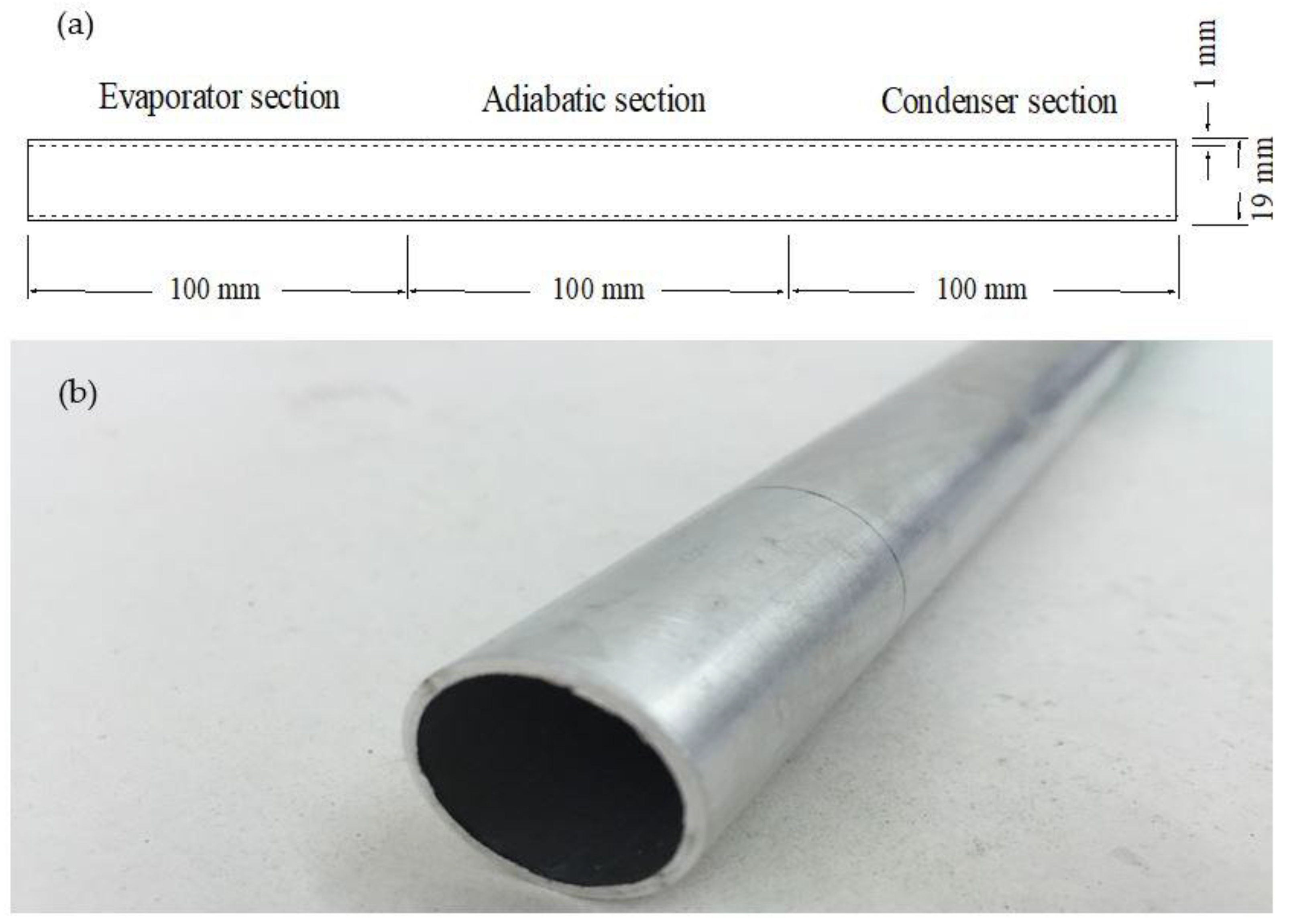
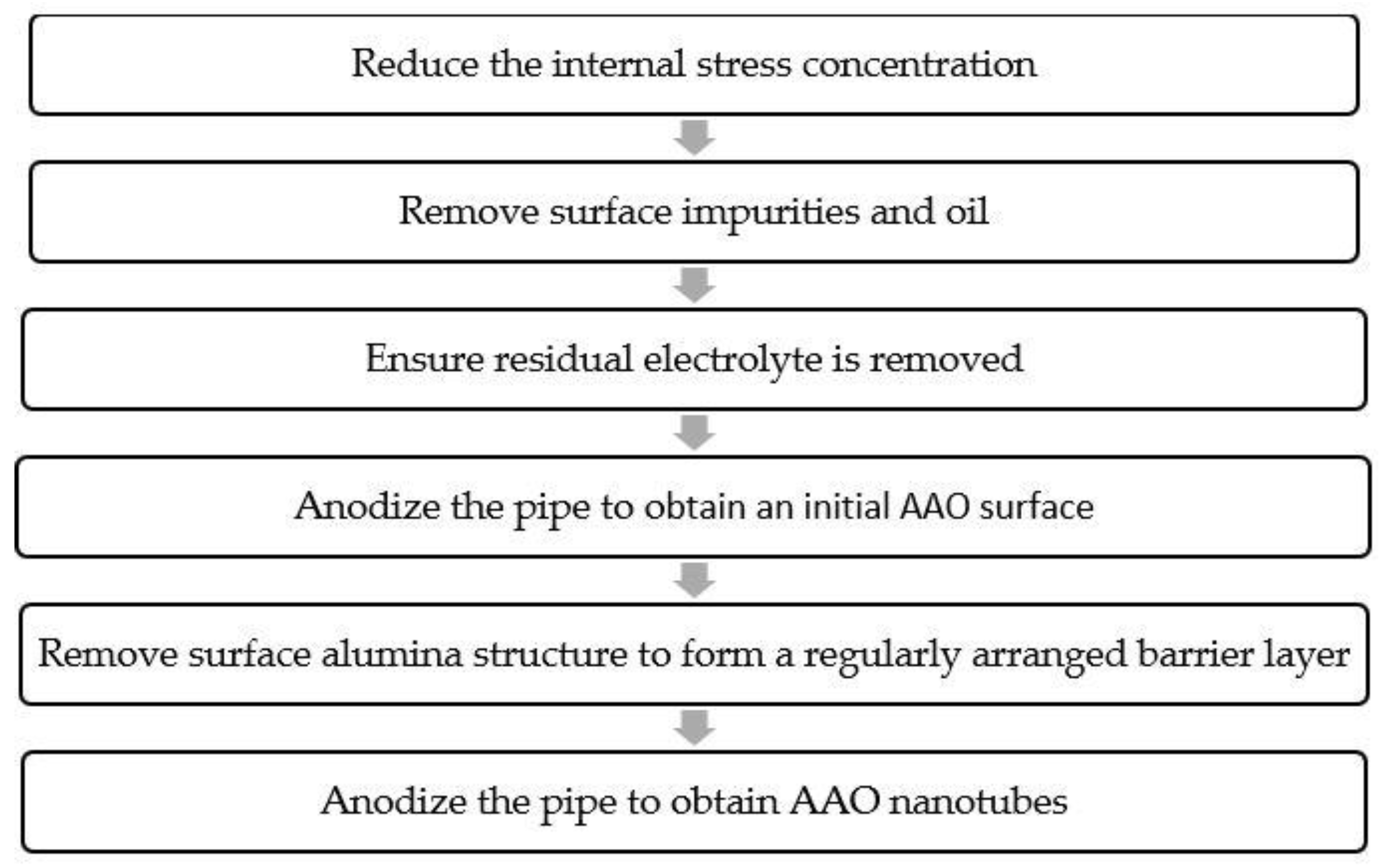
6063-T5 aluminum alloy was used as the base material for the gravity heat pipes in the present study. The aluminum alloy pipes fabricated by a machining process have an outer diameter of 19 mm, an inner diameter of 17 mm, and a pipe length of 300 mm, as shown in Figure 1. The ratio between evaporator section, adiabatic section, and condenser section is 1:1:1. To grow AAO nanotubes on the inner wall surface of the evaporator section of aluminum alloy gravity heat pipes, the following anodic oxidation treatment procedure, also shown in Figure 2, was designed for each pipe:
- An open-ended hollow aluminum alloy pipe was annealed at 450 °C for 3 h to reduce the internal stress concentration.
- A first mechanical polishing was performed on the pipe using #600, #1200, and #2000 sandpapers, sequentially; then, a second mechanical polishing was performed using a polishing fleece with 0.1 µm alumina powder to make the inner wall surface of evaporator section smoother. The pipe was then immersed in acetone (CH3COCH3) and ethanol (C2H6O), respectively, washed for 30 min using an ultrasonic cleaner, and rinsed with deionized (DI) water to remove surface impurities and oil.
- The pipe was connected to the anode, a copper bar was connected to the cathode, and both were then immersed in an electrolytic solution (2:1:1 ratio of phosphoric acid (H3PO4), sulfuric acid (H2SO4) and DI water) and subjected to electrolytic polishing at a current of 15 A to ensure that any scratches left after mechanical polishing were removed. After 90 s of polishing, the pipe was taken out and allowed to cool to room temperature. The same chemical polishing process was completed three times. It should be noted here that a PET insulation tape was attached to the outer wall of the pipe to block the chemical polishing on the outside of the pipe. Finally, the pipe was rinsed with DI water to ensure residual electrolyte is removed.
- The pipe was reconnected to the anode, a 0.25-inch-diameter copper bar was placed in the center of the pipe and connected to the cathode, and both were then immersed in an oxalic acid (H2C2O4) electrolyte with a concentration of 0.3 M. A particular anodizing voltage was applied to the first anodizing treatment step at a working temperature of 5 °C. It should be noted here that a micropump and a magnet stirrer are used to ensure that the concentration of electrolyte during the treatment is relatively uniform. The treatment time was maintained at 2 h, and, after the treatment was completed, the residual electrolyte was removed by rinsing with DI water to obtain an initial AAO surface.
- The anodized pipe was then immersed in undiluted phosphoric acid (H3PO4) for surface removal with the help of an ultrasonic bath. After 2 h surface removal, a regularly arranged barrier layer on surface was left. Acetone and ethanol were again used, respectively, to ultrasonically wash the pipe for 30 min, and DI water was then used to remove the residual phosphoric acid on the surface. The AAO barrier layer could serve as a basis for further generation of AAO nanotubes.
- The second anodizing treatment was performed on the pipe with the AAO barrier layer in the previous manner to obtain AAO nanotubes on the inner wall surface of the evaporator section of the heat pipe. In this treatment stage, the length of AAO nanotubes increased with the treatment time.
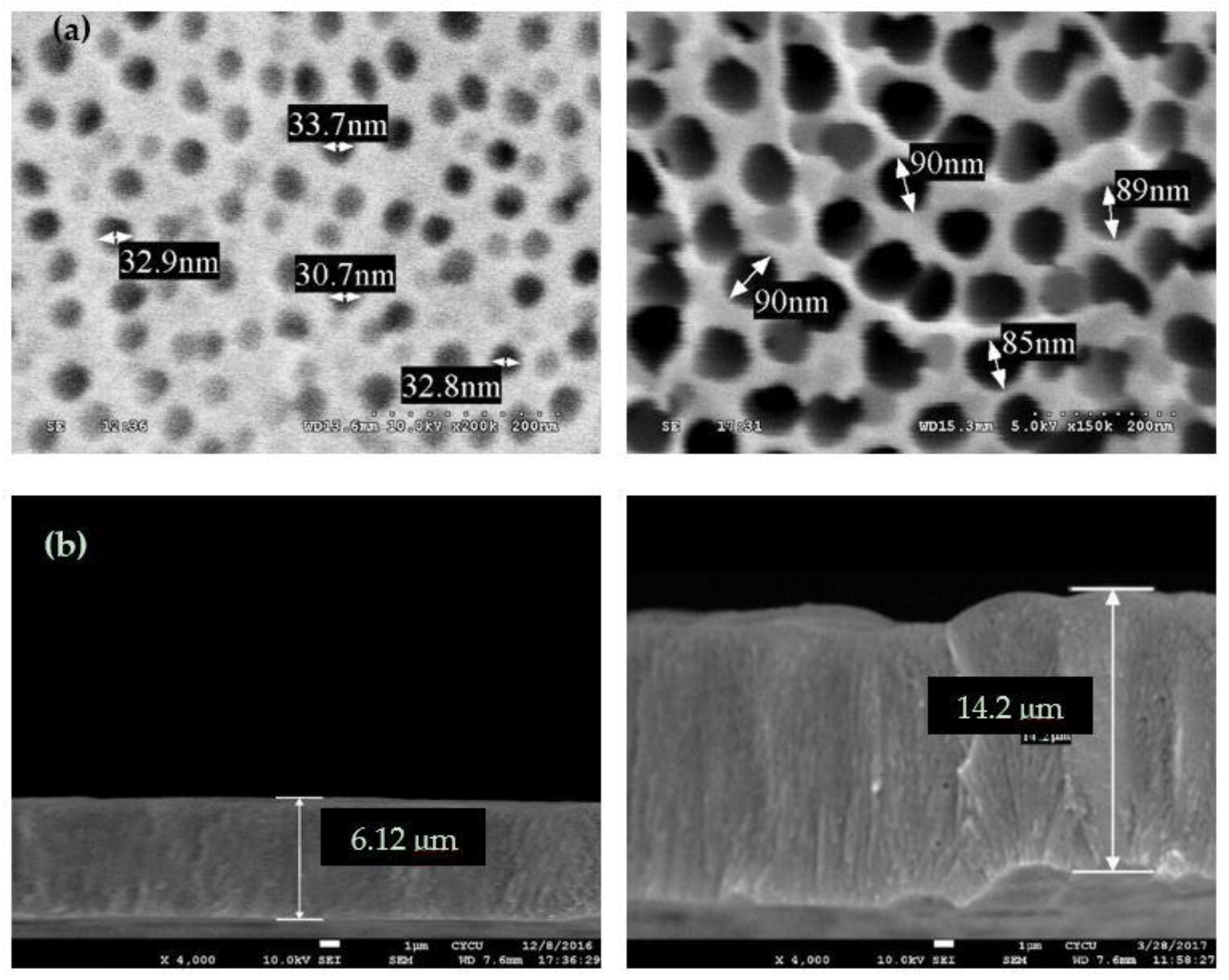
- In our experiments, the anodizing voltage applied was in the range of 20–50 V, and the treatment time consumed was in the range of 3–9 h. The average diameter and length of the AAO nanotubes measured by scanning electron microscope (SEM) imaging method are almost proportional to the anodizing voltage and the treatment time, respectively, as shown in Equations (1) and (2). Figure 3 shows the SEM images of AAO nanotube surfaces obtained at particular anodizing voltages (20 V and 50 V) and particular treatment times (3 h and 7 h).
2.2.2. Processing and Performance Test
The main body of the heat pipe used in this study is an anodized open-ended hollow aluminum alloy pipe. The pipe was first immersed in ethanol and cleaned with an ultrasonic cleaner for 20 min and then rinsed with DI water to ensure its internal surface was clean and free of impurities. Next, both its open ends were sealed by welding, and one end was equipped with an anti-leak valve. Evacuation and working fluid (acetone) filling were then performed down to a pressure of 5 kPa and up to an amount of 40 mL through this valve to complete an aluminum alloy heat pipe having AAO nanotubes on the inner wall surface of the evaporator section, as shown in Figure 4.
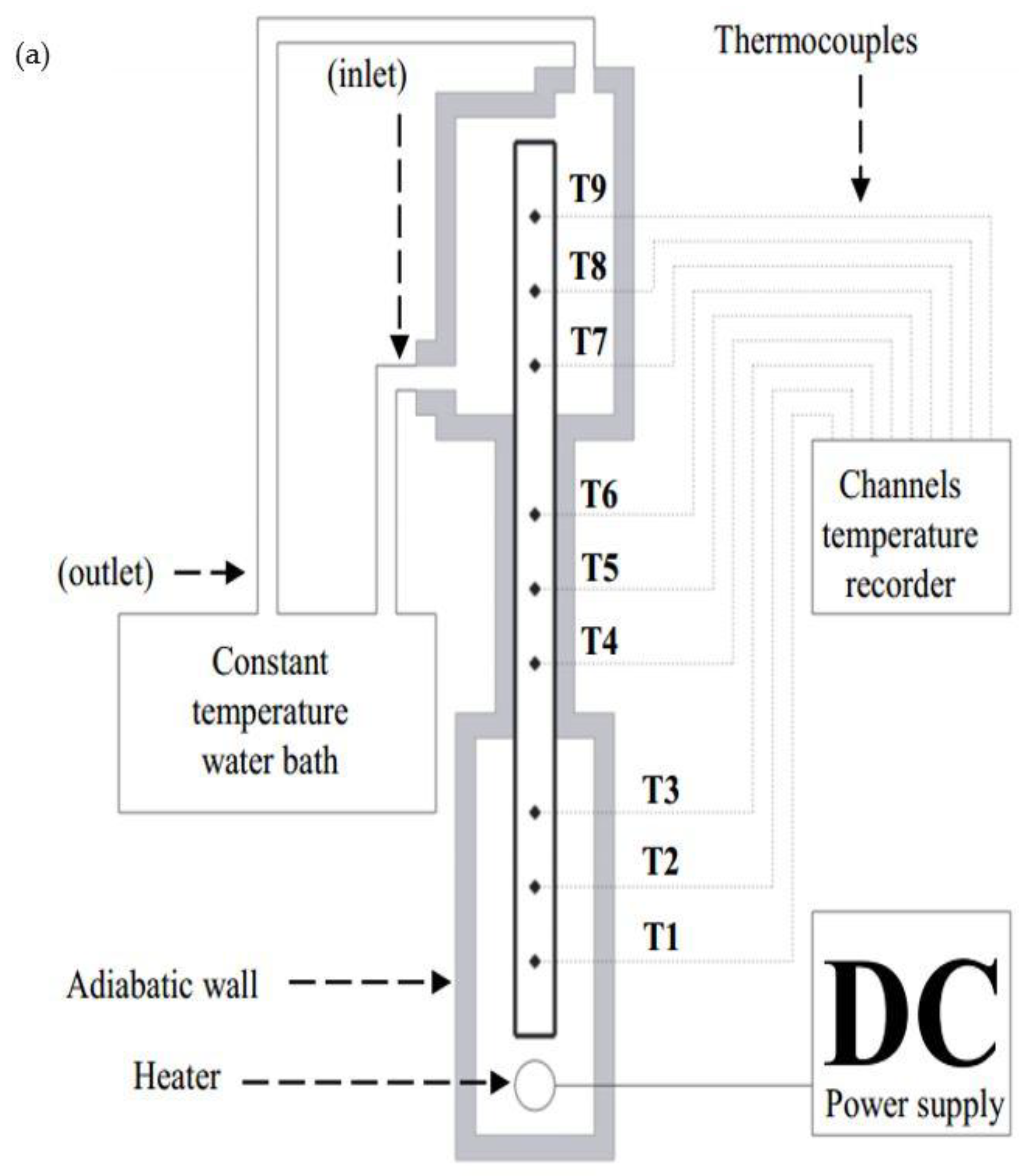
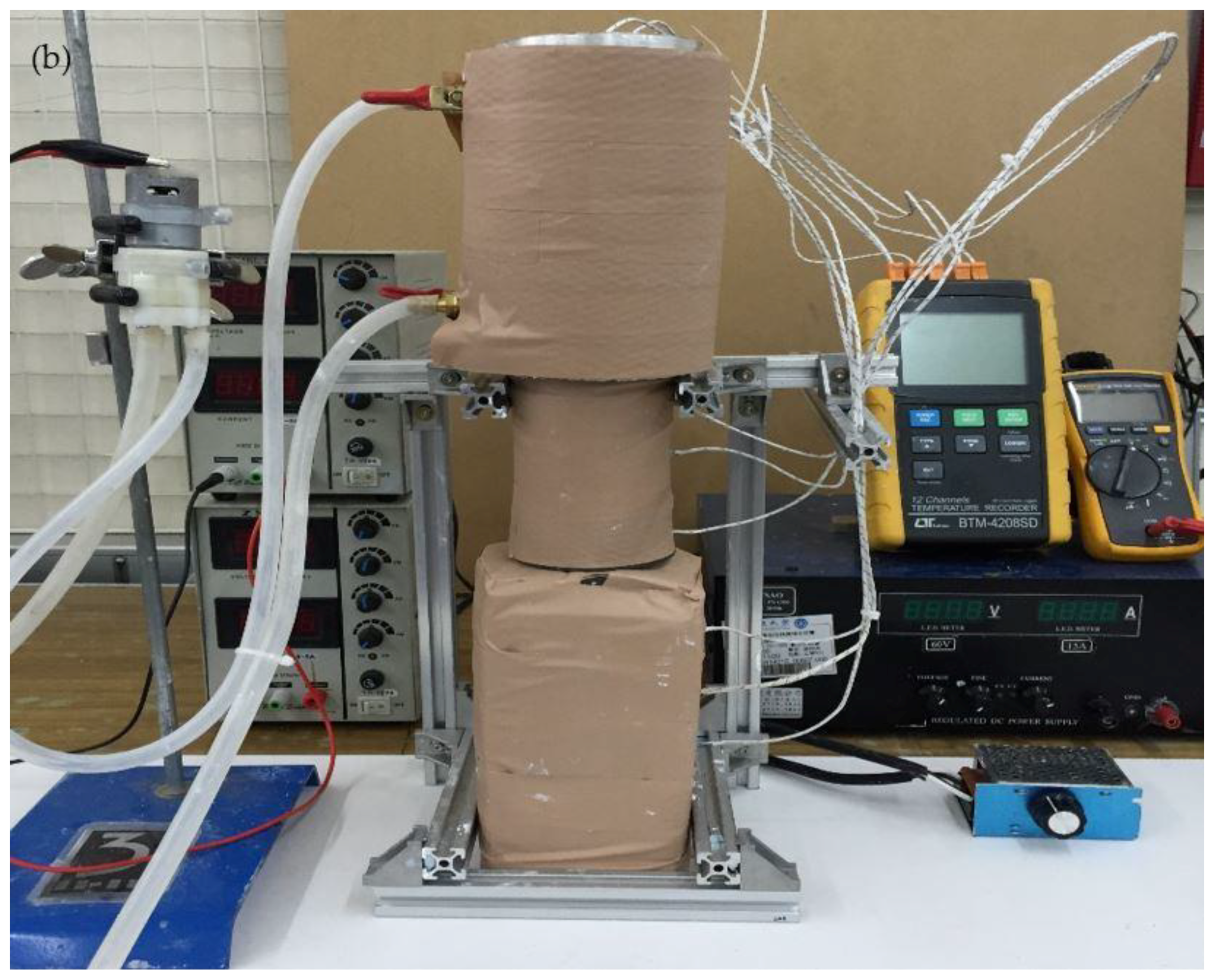
In this study, a thermal performance test system was set up, as shown in Figure 5. The test system can be divided into three zones: the heating zone, the transportation zone, and the cooling zone. Each zone was covered with three layers of insulation material (fireproof cotton, calcium silicate board, and polyethylene foam board) to ensure that no heat exchange with the surrounding environment occured during the test, resulting in heat loss. The evaporator section of the heat pipe was placed vertically in the heating zone, where the heater was connected to a DC power supply to provide the required thermal power. The condenser section of the heat pipe was placed vertically in the cooling zone, and the temperature inside the cooling zone was maintained at 25 °C by a circulating water bath. Three K-type thermocouples were embedded in each area with equal distance (30 mm) and connected to a temperature recorder to fully record the exact temperatures during the test. Through the measured temperature data, the thermal performance of the gravity heat pipe can then be further analyzed. This study used the overall thermal resistance of the gravity heat pipe (R) as one of the key parameters to investigate the heat transfer performance of gravity heat pipes, defined as the ratio of the difference between the average temperature of the evaporator section () and the average temperature of the condenser section () to the input heat power from the heating zone (Qin). The relationship is as follows:
The absolute relative uncertainty of the quantity defined in the above equation was estimated to be less than 2.77%.
3. Results and Discussion
Now, we consider the problem of heat transfer performance enhancement of gravity heat pipes by growing AAO nanotubes on inner wall surface. The influences of AAO nanotube length and diameter on the temperature distribution, overall thermal resistance, and dry-out occurrence of the processed gravity heat pipes under different input heat powers (symbol: Qin) were analyzed, respectively. Parameter studies were carried out within the ranges: , , and .
3.1. Temperature Distributions
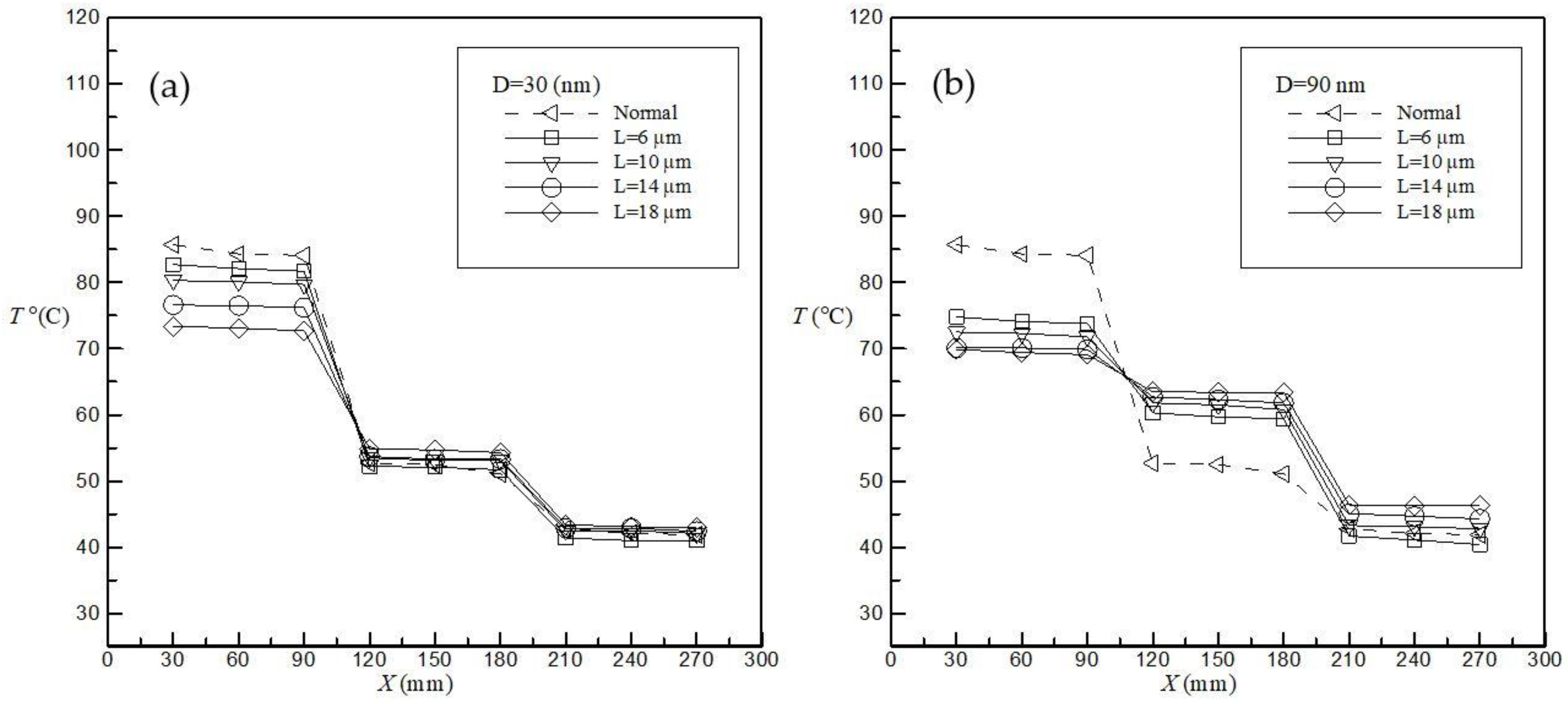
When the electronic components in a computer perform related calculations, the waste heat generated will affect the operating speed, and, as the temperature rises, excessive temperatures will cause the hardware to crash or even cause permanent damage. In Figure 6, the temperature T versus the position X is plotted for the AAO nanotube length , , , and with the AAO nanotube diameter D = 30 nm (Figure 6a) and D = 90 nm (Figure 6b) under a heat power condition of Qin = 100 W. The results show that, at a particular tube diameter D, in the evaporator section, the temperature decreases with the increase in the tube length L. The reason for the decrease in temperature may be that the growth of the tube length can increase the specific surface area, so that the working fluid can transfer more thermal energy from the heat source through the solid surface, thereby improving the heat transfer performance of the heat pipe. In the condenser section, the temperature increases as the tube length increases. The reason is that the thermal energy of the heat source is more brought from the evaporator section to the condenser section, so that the condenser section has the opportunity to remove more waste heat, thereby improving the heat transfer performance. In addition, comparing Figure 6a,b, it can be seen that the temperature in the evaporator section decreases with the increase in the tube diameter D.
The reason may be that the increase in the tube diameter makes the nucleation sites larger, resulting in larger bubbles, and, when the working fluid boils, the mutual interference between the generated bubbles is more severe, thereby promoting the convective boiling effect to enhance the heat transfer performance of the heat pipe. In the condenser section, the temperature increases as the tube diameter increases. The reason for this is that the convective boiling effect is greatly enhanced in the evaporator section, so that the condenser section has the opportunity to remove more waste heat, thereby improving the heat transfer performance. The maximum percentage decrease in temperature for the heat power of 100 W is 18.44% and in the temperature difference between the evaporator section and the condenser section is 46.12%, compared to the unprocessed heat pipe (dashed line).
3.2. Thermal Resistance versus Nanotube Size
Figure 7 shows the overall thermal resistance R versus the tube diameter D for the AAO nanotube length , , , and with the input heat power Qin = 25 W (Figure 7a) and Qin = 100 W (Figure 7b). In Figure 7, at a given heat power, the overall thermal resistance R decreases with increasing the tube diameter D. The reason may be that the enlargement of the tube diameter makes the nucleation sites larger, and, when the working fluid boils, the more severe the mutual interference between the generated bubbles, the stronger the convective boiling effect, and the better the heat transfer performance of the heat pipe. In addition, the overall thermal resistance R decreases with increasing the tube length L. The reason is that the growth of the tube length can increase the specific surface area, the working fluid can transfer more thermal energy from the heat source through the solid surface, and then enhance the heat transfer performance of the heat pipe. It can also be found that along with the growth of the tube length L, the overall thermal resistance R does not change significantly with the change of the diameter D; that is, there is no significant change in the variation trend of R and D. In addition, comparing Figure 7a,b it can be found that, with the increase of the input heat power Qin, the variation trend of R and D tends to be gentle, and the influences of tube diameter and tube length become less obvious. The reason for this is that higher input heat power will lead to an increase in the overall temperature of the working fluid in the heat pipe, leading to less pronounced surface structure effects. The maximum percentage decrease in overall thermal resistance for the heat power of 25 W is 58.68%, compared to the unprocessed heat pipe (dashed line).
3.3. Occurrence of Dry-Out Phenomenon
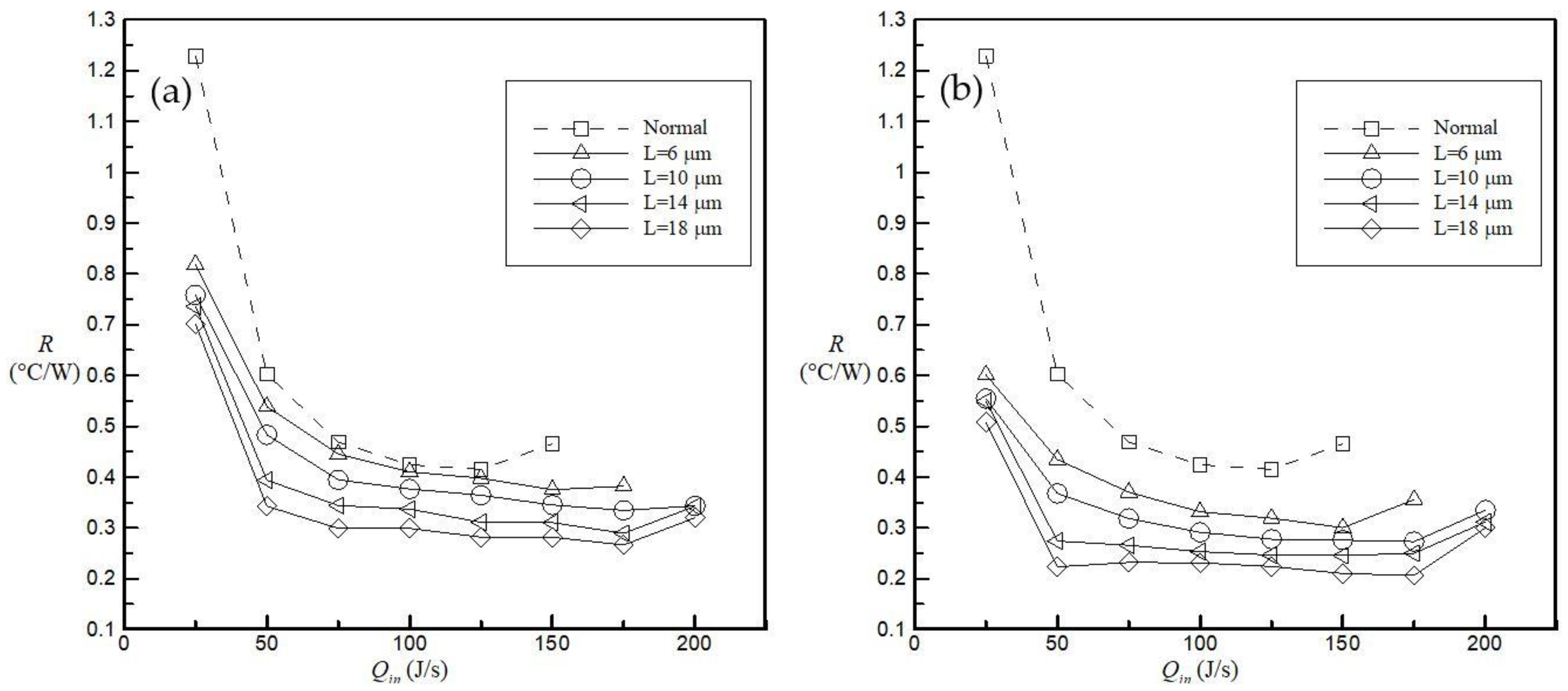
Figure 8 examines the overall thermal resistance R versus the input heat power Qin for the AAO nanotube length , , , and with the AAO nanotube diameter D = 30 nm (Figure 8a) and D = 90 nm (Figure 8b). In Figure 8, the overall thermal resistance R generally decreases as the input heat power Qin increases, and tends to be gentle. However, when the quality in the evaporator section reaches 100%, the temperature of the evaporator section suddenly rises, resulting in a sudden increase in the overall thermal resistance R. At this point, it can be judged that a dry-out phenomenon has occurred. The dry-out phenomenon occurs when the heat input heat power Qin is greater than 125 W, 150 W, 175 W, 175 W, and 175 W in the cases of tube lengths L = 0 µm (unprocessed heat pipe), 6 µm, 10 µm, 14 µm, and 18 µm, respectively. This means that the dry-out occurrence can be delayed due to the surface structure. This reason is that the growth of the tube length can increase the specific surface area, so that the working fluid can transfer more energy from the heat source through the solid surface, thereby reducing the heat accumulation and delaying the occurrence of dry-out phenomenon. In addition, comparing Figure 8a,b, it can be found that by increasing the tube diameter D, the overall thermal resistance R can be further reduced, but the tube diameter does not seem to have the effect of delaying the dry-out occurrence. Compared to the unprocessed heat pipe (dashed line), the maximum applicable input heat power to avoid dry-out occurrence can be increased up to about 40%.
4. Conclusions
Thus far, no study has been conducted to investigate the influence of inner surface morphology of gravity heat pipes on the heat transfer performance. This study therefore has experimentally studied the effects of the length and diameter of anodic aluminum oxide (AAO) nanotubes on the temperature distribution, overall thermal resistance, and dry-out occurrence of gravity heat pipes charged with acetone under different input heat powers. First, AAO nanotubes were grown by anodizing the inner wall surface of the evaporator section of aluminum alloy gravity heat pipes. Then, the influences of surface morphology on the temperature distribution, overall thermal resistance, and dry-out occurrence were investigated by using a thermal performance test system.
The research results obtained are as follows:
- Increasing the AAO nanotube length and diameter could result in reduced temperature variation between the evaporator section and the condenser section. The maximum percentage decrease in temperature difference between the evaporator section and the condenser section compared to the unprocessed heat pipe is 46.12%.
- Increasing the AAO nanotube length and diameter could lead to the reduction of the overall thermal resistance. The maximum percentage decrease in overall thermal resistance compared to the unprocessed heat pipe is 58.68%.
- The dry-out occurrence can be delayed due to the growth of the AAO nanotube length, but it cannot be not affected by the increase in diameter. The maximum applicable input heat power to avoid dry-out occurrence can be increased up to about 40%, compared to the unprocessed heat pipe.
This paper mainly focuses on the detailed information about the influences of AAO nanotube size on the heat transfer performance of gravity heat pipes. In the future, different types of heat pipes such as two-phase closed thermosyphons, capillary-driven heat pipes, annular heat pipes, pulsating heat pipes, and micro/miniature heat pipes of different materials can be used for surface treatment, not limited to anodic oxidation treatment, and their heat transfer performance can be experimentally and theoretically investigated. In addition, since it is expected that the addition of nanostructures in the working fluid can provide enhanced heat transfer, the influence of fluid suspensions of nanostructures on the heat transfer performance of surface-treated heat pipes can be further studied in the future.
Author Contributions
M.-H.Y. conceived and designed the experiments, performed the experiments, analyzed the data, and prepared figures. H.C.W. planned the research project, analyzed the data, and wrote the paper.
Funding
This work was financially supported by the Ministry of Science and Technology (MOST) in Taiwan under grant No 106-2221-E-033-040.
Conflicts of Interest
The authors declare no conflict of interest.
References
- Shabgard, H.; Allen, M.J.; Sharifi, N.; Benn, S.P.; Faghri, A.; Bergman, T.L. Heat pipe heat exchangers and heat sinks: Opportunities, challenges, applications, analysis, and state of the art. Int. J. Heat Mass Transf. 2015, 89, 138–158. [Google Scholar] [CrossRef]
- Xue, H.S.; Fan, J.R.; Hu, Y.C.; Hong, R.H.; Cen, K.F. The interface effect of carbon nanotube suspension on the thermal performance of a two-phase closed thermosyphon. J. Appl. Phys. 2006, 100, 104909. [Google Scholar] [CrossRef]
- Liu, Z.H.; Yang, X.F.; Guo, G.L. Effect of nanoparticles in nanofluid on thermal performance in a miniature thermosyphon. J. Appl. Phys. 2007, 102, 013526. [Google Scholar] [CrossRef]
- Khandekar, S.; Joshi, Y.M.; Mehta, B. Thermal performance of closed two-phase thermosyphon using nanofluids. Int. J. Therm. Sci. 2008, 47, 659–667. [Google Scholar] [CrossRef]
- Noie, S.H.; Heris, S.Z.; Kahani, M.; Nowee, S.M. Heat transfer enhancement using Al2O3/water nanofluid in a two-phase closed thermosyphon. Int. J. Heat Fluid Flow 2009, 30, 700–705. [Google Scholar] [CrossRef]
- Paramatthanuwat, T.; Boothaisong, S.; Rittidech, S.; Booddachan, K. Heat transfer characteristics of a two-phase closed thermosyphon using de ionized water mixed with silver nano. Heat Mass Transf. 2010, 46, 281–285. [Google Scholar] [CrossRef]
- Teng, T.P.; Hsu, H.G.; Mo, H.E.; Chen, C.C. Thermal efficiency of heat pipe with alumina nanofluid. J. Alloys Compd. 2010, 504, S380–S384. [Google Scholar] [CrossRef]
- Huminic, G.; Huminic, A.; Morjan, I.; Dumitrache, F. Dumitrache, Experimental study of the thermal performance of thermosyphon heat pipe using iron oxide nanoparticles. Int. J. Heat Mass Transf. 2011, 54, 656–661. [Google Scholar] [CrossRef]
- Yang, X.F.; Liu, Z.H. Application of functionalized nanofluid in thermosyphon. Nanoscale Res. Lett. 2011, 6, 494. [Google Scholar] [CrossRef] [PubMed] [Green Version]
- Chen, Y.J.; Wang, P.Y.; Liu, Z.H. Application of water-based SiO2 functionalized nanofluid in a loop thermosiphon. Int. J. Heat Mass Transf. 2013, 56, 59–68. [Google Scholar] [CrossRef]
- Kamyar, A.; Ong, K.S.; Saidur, R. Effects of nanofluids on heat transfer characteristics of a two-phase closed thermosyphon. Int. J. Heat Mass Transf. 2013, 65, 610–618. [Google Scholar] [CrossRef]
- Buschmann, M.H.; Franzke, U. Improvement of thermosyphon performance by employing nanofluid. Int. J. Refrig.-Rev. Int. Froid 2014, 40, 416–428. [Google Scholar] [CrossRef]
- Asirvatham, L.G.; Wongwises, S.; Babu, J. Heat transfer performance of a glass thermosyphon using graphene-acetone nanofluid. Heat Transf.-Trans. ASME 2015, 137, 111502. [Google Scholar] [CrossRef]
- Zhao, S.; Xu, G.; Wang, N.; Zhang, X. Experimental study on the thermal start-up performance of the graphene/water nanofluid-enhanced solar gravity heat pipe. Nanomaterials 2018, 8, 72. [Google Scholar] [CrossRef] [PubMed]
- Solomon, A.B.; Ramachandran, K.; Pillai, B.C. Thermal performance of a heat pipe with nanoparticles coated wick. Appl. Therm. Eng. 2012, 36, 106–112. [Google Scholar] [CrossRef]
- Solomon, A.B.; Mathew, A.; Ramachandran, K.; Pillai, B.C.; Karthikeyan, V.K. Thermal performance of anodized two phase closed thermosyphon (TPCT). Exp. Therm. Fluid Sci. 2013, 48, 49–57. [Google Scholar] [CrossRef]
- Singh, R.R.; Selladurai, V.; Ponkarthik, P.K.; Solomon, A.B. Effect of anodization on the heat transfer performance of flat thermosyphon. Exp. Therm. Fluid Sci. 2015, 68, 574–581. [Google Scholar] [CrossRef]
- Solomon, A.B.; Daniel, V.A.; Ramachandran, K.; Pillai, B.C.; Singh, R.R.; Sharifpur, M.; Meyer, J.P. Performance enhancement of a two-phase closed thermosiphon with a thin porous copper coating. Int. J. Heat Mass Transf. 2017, 82, 9–19. [Google Scholar] [CrossRef]
- Tharayil, T.; Asirvatham, L.G.; Rajesh, S.; Wongwises, S. Effect of nanoparticle coating on the performance of a miniature loop heat pipe for electronics cooling applications. J. Heat Transf.-Trans. ASME 2018, 140, 022401. [Google Scholar] [CrossRef]
- Li, A.P.; Muller, F.; Birner, A.; Nielsch, K.; Gosele, U. Hexagonal pore arrays with a 50–420 nm interpore distance formed by self-organization in anodic alumina. J. Appl. Phys. 1998, 84, 6023–6026. [Google Scholar] [CrossRef]
- Thompson, G.E.; Wood, G.C. Porous anodic film formation on aluminium. Nature 1981, 290, 230–232. [Google Scholar] [CrossRef]
- Chien, Y.-C.; Weng, H.C. A brief note on the magnetowetting of magnetic nanofluids on AAO surfaces. Nanomaterials 2018, 8, 118. [Google Scholar] [CrossRef] [PubMed]
Figure 1.
Aluminum alloy pipe: (a) Schematic drawing; and (b) photograph.

Figure 2.
Anodic oxidation treatment procedure for each pipe.

Figure 3.
(a) AAO nanotube diameters obtained at anodizing voltages of 20 V and 50 V; and (b) AAO nanotube lengths obtained at treatment times of 3 h and 7 h.
Figure 3.
(a) AAO nanotube diameters obtained at anodizing voltages of 20 V and 50 V; and (b) AAO nanotube lengths obtained at treatment times of 3 h and 7 h.

Figure 4.
Gravity heat pipe: (a) Schematic drawing; and (b) photograph.
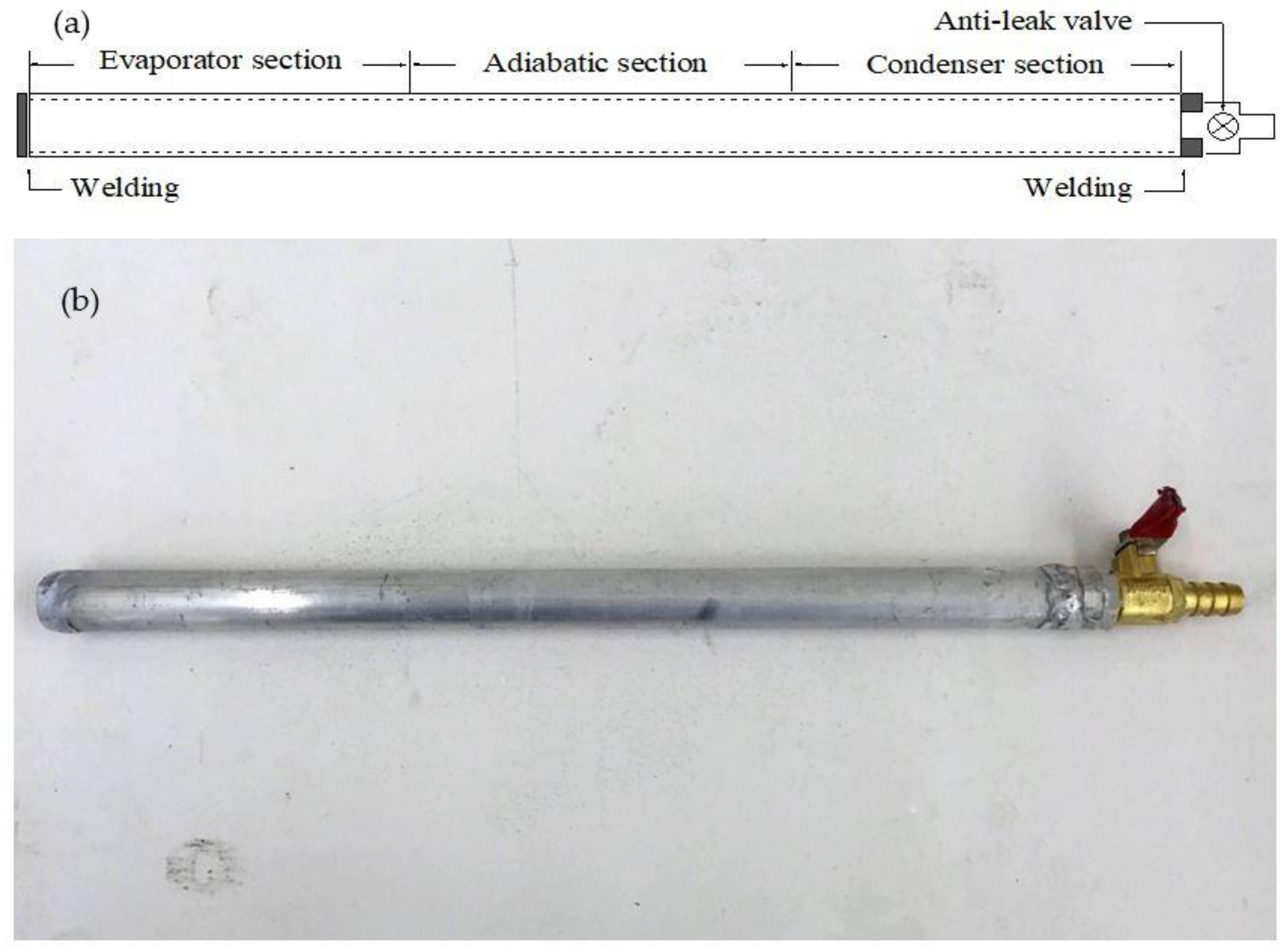
Figure 5.
Thermal performance test system: (a) Schematic drawing; and (b) photograph.


Figure 6.
Temperature distribution along heat pipe at Qin = 100 W for different values of the tube length L with: (a) D = 30 nm; and (b) D = 90 nm.
Figure 6.
Temperature distribution along heat pipe at Qin = 100 W for different values of the tube length L with: (a) D = 30 nm; and (b) D = 90 nm.

Figure 7.
Variation of the overall thermal resistance R with the tube diameter D for different values of the tube length L with: (a) Qin = 25 W; and (b) Qin = 100 W.
Figure 7.
Variation of the overall thermal resistance R with the tube diameter D for different values of the tube length L with: (a) Qin = 25 W; and (b) Qin = 100 W.
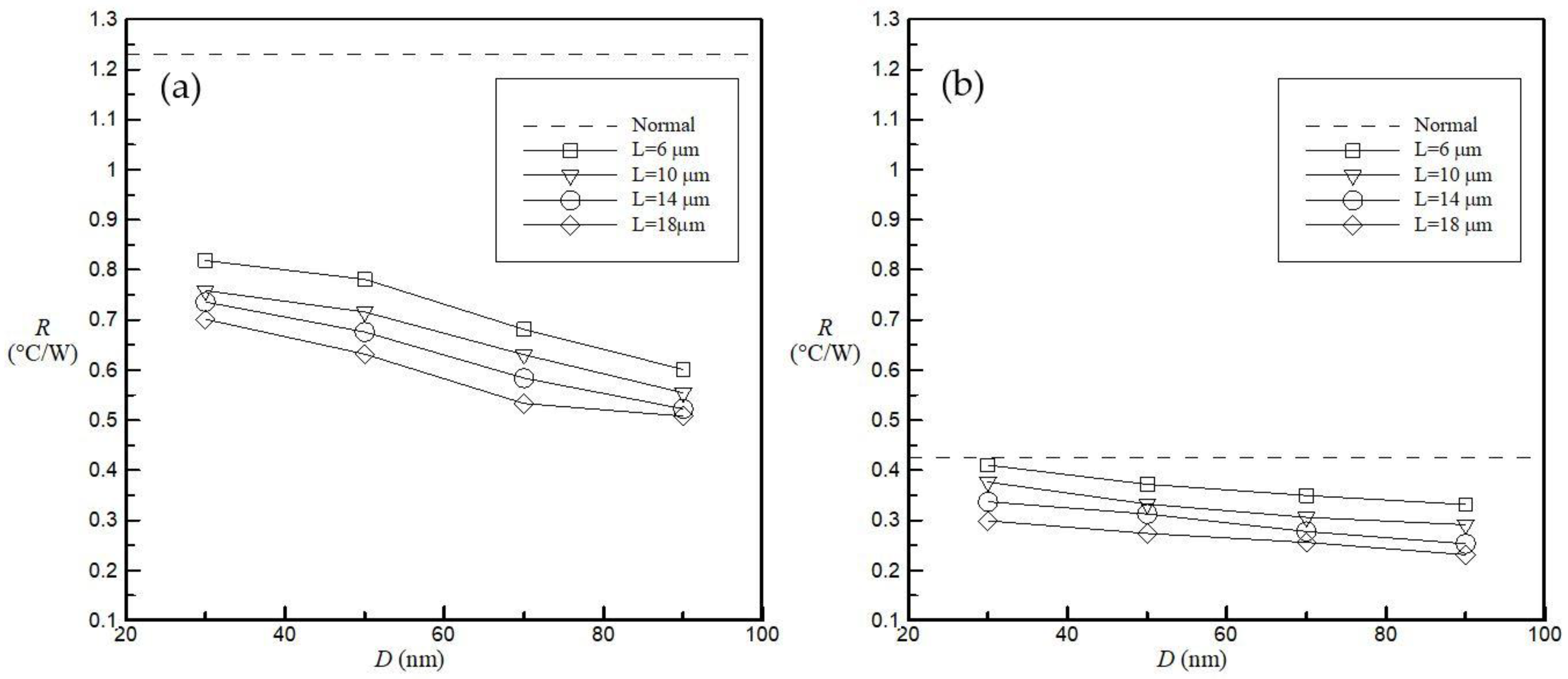
Figure 8.
Variation of the overall thermal resistance R with the input heat power Qin for different values of the tube length L with: (a) D = 30 nm; and (b) D = 90 nm.
Figure 8.
Variation of the overall thermal resistance R with the input heat power Qin for different values of the tube length L with: (a) D = 30 nm; and (b) D = 90 nm.
© 2018 by the authors. Licensee MDPI, Basel, Switzerland. This article is an open access article distributed under the terms and conditions of the Creative Commons Attribution (CC BY) license (http://creativecommons.org/licenses/by/4.0/).
Share and Cite
MDPI and ACS Style
Weng, H.C.; Yang, M.-H. Heat Transfer Performance Enhancement of Gravity Heat Pipes by Growing AAO Nanotubes on Inner Wall Surface. Inventions 2018, 3, 42. https://doi.org/10.3390/inventions3030042
AMA Style
Weng HC, Yang M-H. Heat Transfer Performance Enhancement of Gravity Heat Pipes by Growing AAO Nanotubes on Inner Wall Surface. Inventions. 2018; 3(3):42. https://doi.org/10.3390/inventions3030042
Chicago/Turabian StyleWeng, Huei Chu, and Meng-Hsueh Yang. 2018. "Heat Transfer Performance Enhancement of Gravity Heat Pipes by Growing AAO Nanotubes on Inner Wall Surface" Inventions 3, no. 3: 42. https://doi.org/10.3390/inventions3030042