Article

Examining the Effect of Flow Rate Ratio on Droplet Generation and Regime Transition in a Microfluidic T-Junction at Constant Capillary Numbers

by
Katerina Loizou
1,†,
Voon-Loong Wong
2,‡ and
Buddhika Hewakandamby
1,*
1
Department of Chemical and Environmental Engineering, University of Nottingham, Nottingham NG7 2RD, UK
2
Department of Chemical and Environmental Engineering, University of Nottingham Malaysia Campus, Semenyih 43500, Malaysia
*
Author to whom correspondence should be addressed.
Current address: Department of Chemical Engineering, University College London, London WC1E 7JE, UK.
Current address: School of Engineering and Physical Sciences, Heriot-Watt University Malaysia Campus, Putrajaya Wilayah Persekutuan 62200, Malaysia.
Inventions 2018, 3(3), 54; https://doi.org/10.3390/inventions3030054
Submission received: 16 July 2018 / Revised: 7 August 2018 / Accepted: 8 August 2018 / Published: 10 August 2018
(This article belongs to the Special Issue Microfluidics and Nanofluidics)

Abstract

:
The focus of this work is to examine the effect of flow rate ratio (quotient of the dispersed phase flow rate over the continuous phase flow rate) on a regime transition from squeezing to dripping at constant capillary numbers. The effect of the flow rate ratio on the volume of droplets generated in a microfluidic T-junction is discussed, and a new scaling law to estimate their volume is proposed. Existing work on a regime transition reported by several researchers focuses on the effect of the capillary number on regime transition, and the results that are presented in this paper advance the current understanding by indicating that the flow rate ratio is another parameter that dictates regime transition. In this paper, the transition between squeezing and dripping regimes is reported at constant capillary numbers, with a transition region identified between squeezing and dripping regimes. Dripping is observed at lower flow rate ratios and squeezing at higher flow rate ratios, with a transition region between the two regimes at flow rate ratios between 1 and 2. This is presented in a flow regime map that is constructed based on the observed mechanism. A scaling model is proposed to characterise droplet volume in terms of flow rate ratio and capillary number. The effect of flow rate ratio on the non-dimensional droplet volume is presented, and lastly, the droplet volume is expressed in terms of a range of parameters, such as the viscosity ratio between the dispersed and the continuous phase, capillary number, and the geometrical characteristics of the channels.

1. Introduction

The tight control of droplets and bubbles generated in microfluidic devices has become pivotal, due to the multifaceted applications that they have, both in research as well as in industrial operations. The ability to generate highly uniform structures (plugs, bubbles, or droplets) has rendered microfluidics as a promising field for a wide range of applications, from particle synthesis, to microreactors and microanalytical devices. As the need to generate uniform droplets in a controlled manner is the motivation, the aim of this work is to unveil the effect of the flow rate ratio on droplet generation. One of the most widely studied microfluidic geometries to generate droplets or bubbles is the T-junction geometry with a side arm that feeds one phase to a main channel, where the second immiscible phase flows. When the two immiscible fluids flow in this geometrical configuration, droplets of the phase that does not wet the channel walls are generated. The generation of such droplets consists of three stages; (i) the fluid to be dispersed flows through the side arm penetrating the continuous phase flow in the main channel, at the vicinity of the T-junction; (ii) the emerging thread grows downstream under the continuous phase effect; and (iii) a droplet is sheared off and carried by the continuous phase downstream of the main channel. To describe the mechanism of droplet formation in microfluidic T-junctions, two prevailing approaches can be distinguished. Thorsen et al. [1], described the formation as a result of the competition between the shear forces acting to pinch a droplet off the emerging dispersed phase thread, and the interfacial tension acting on stabilising it. The second approach, as summarised by Garstecki et al. [2], postulates that the effect of shear stress is not significant at lower capillary numbers. The “rate-of-flow controlled” break-up mechanism attributed the droplet pinch-off to lower capillary numbers on the balance of pressures in the continuous and dispersed phase. However, they identified a transition point at a critical value of capillary number, above which the shear stress effect has to be accounted for. Extensive work has been performed over the last decades in an attempt to describe and characterise the break-up mechanism in a microfluidic T-junction, both in Newtonian and non-Newtonian systems [1,2,3,4,5,6,7,8,9]. Droplets are detached from the dispersed phase threads penetrating the continuous phase, either near the junction or several widths downstream, depending on the flow rates, the fluid properties, and the geometrical characteristics of the system [4,5]. Three distinct regimes have been identified for the droplet breakup process in a microfluidic T-junction by various research groups, namely squeezing, dripping, and jetting in Newtonian systems [2,4,6]. Mapping of these flow regimes and patterns at different parametric conditions, as well as characterising the transition between the regimes mentioned above, is vital for the design and operation of microfluidic devices. The transition between these regimes has been characterised by using the capillary number [4,6]. Additionally, Nisisako et al. [5], as well as Tice et al. [10], have used capillary number to predict the patterns of droplet formation. The capillary number is defined as “the parameter measuring the distorting forces due to the flow relative to the interfacial tension opposing the distortion” [11], given by the formula
C a = μ U / γ ,
where μ is the dynamic viscosity of the continuous phase, U is the velocity of the continuous phase, and γ is the interfacial tension between the continuous and the dispersed phase.
The squeezing regime has been reported to be observed at low values of capillary number, and the preponderant explanation is that the break-up is due to the build-up of pressure upstream of the emerging droplet [3,12]. This build-up of pressure is attributed to the restriction of the area available for the continuous phase to flow. The emerging droplet occupies most of the cross-section of the continuous phase channel before being pinched off. When the droplet is detached from the liquid thread, a sharp decrease of pressure has been reported [3].
The dripping regime has been reported to occur at higher capillary numbers [6]. During dripping, droplets are sheared off before they fill the cross-section of the channel, where the shear force exerted on the droplet is acting against the interfacial force [6]. The pressure build-up upstream of the emerging droplet cannot be neglected, and it is expected to facilitate break up [6,13]. Dripping is stated to occur over a short range of capillary numbers [6] before the jetting regime becomes dominant. Generally, during the dripping regime, smaller droplets are generated compared to the squeezing regime [6]. In the jetting regime, the two immiscible phases flow in parallel in the main channel, in what is described as “laminar flow side-by-side”, with the dispersed phase forming a jet [6] before a droplet is detached several width lengths downstream [13].
The transition between these regimes has been described by several researchers using mostly the capillary number (Ca), calculated using the parameters associated with the continuous phase [3,13,14]. Experimental work performed by Garstecki et al. [3], validated by numerical simulations performed by De Menech et al. [6], indicated a notable change in the behaviour above a critical capillary number of 0.01. This change in behaviour was explained in terms of the effect of the shear stress on the break-up mechanism. They suggested that as the shear stress starts to contribute significantly to the break-up mechanism, smaller droplets are generated. The observed behaviour is similar ‘to the dripping regime in an unbounded, co-flowing liquid’ [3]. Additionally, Christopher et al. [13] studied the transition from squeezing to dripping in a microfluidic T-junction. They commented that for a specific range of conditions, the break-up is influenced by both the squeezing pressure due to the obstruction of the area available for the continuous phase to flow, as well as on the viscous shear stress acting on the emerging thread [13]. Fu et al. [15] have investigated the squeezing-to-dripping transition in a gas-liquid system, and they have reported that during the transitional regime, the break-up mechanism is driven by both the squeezing pressure and the shear stress. An extended study focused on the transitional regime, that included experimental observations and model validation [16,17] has identified that break-up is affected by the geometrical characteristics of the T-junction and the capillary number, as well as the flow rate and viscosity ratio between the two phases. Numerical simulations performed along those lines [6] provided access to different dynamic parameters. The evolution of pressure was used to explain the transition between the regimes. To identify the regimes described above and to distinguish their transitions, visual observations are utilised [3,6,7,8,13,15]. Thus, the identification and the distinction between different regimes is qualitative, and it is subjected to each authors’ judgment, rendering the identification of transition between regimes as a convoluted process. The above explains the discrepancies that arise in terms of the sharp transition between regimes, or the gradual transition that is identified as an intermediate regime by several researchers, and in this manuscript [6,15].
Therefore, most work that is done in identifying and characterising the transition between these distinct regimes [3,6,14], observed these transitions occurring at a critical capillary number (Ca). Nevertheless, the critical capillary number at which the transition between regimes occurs, is evidently affected by the system properties. Christopher et al. [13], supported the critical capillary concept presented by Garstecki et al. [3]; however, they indicated that the fluid properties and geometry have an influence on the regime transition. In addition, they supported that this dependency extends to the dripping regime, and it is not only applicable at the squeezing regime, as reported by Garstecki et al. [2]. The ratios between the widths of the dispersed phase channel and the continuous phase flow channel, as well as the ratio between the viscosities of the two phases, have been found to significantly affect regime transition. It is noteworthy that when a system with high viscosity contrast has been employed, the transition from squeezing to dripping has not been observed [7].
The occurrence of multiple regimes at constant capillary numbers has been reported before by Zangoni et al. [18]. They have demonstrated that at constant capillary numbers for a hydrophilic T-junction, changing the flow rate ratio between the two phases resulted in the observation of different regimes such as squeezing, coflow (parallel flow of the two phases in the channel), dripping, and jetting. Nevertheless, they have observed the transition from dripping to jetting and finally to coflow, or from squeezing to jetting, and then coflow. However, the transition between squeezing and dripping at constant capillary numbers has not been reported. Decreasing the flow rate ratio results in a transition from a regime that is observed at lower capillary numbers, to a regime that is reported to be observed at higher capillary numbers, such as from squeezing to coflow, or dripping to jetting. In the context of microfluidic T-junctions, Gupta et al. [19] commented on the effect of flow rate ratio on the regime transition from droplet flows to parallel flows in the dripping regime. Their simulations demonstrated that at constant capillary numbers, different structures were observed when the flow rate ratio was varied. Extending their work on the squeezing regime, Gupta and Kumar [20] commented that for constant capillary numbers the length of plugs increased linearly with an increase in the flow rate ratio; however the effect of the flow rate ratio on the mechanism of formation has not been discussed. Furthermore, Zangoni et al. [18] indicated that different flow patterns in terms of segmented or co-flowing flows were observed at constant capillary numbers and varying flow rate ratios. Nevertheless, no transition has been observed between squeezing and dripping. The results presented in Liu and Zhang [21], demonstrated a regime transition at constant capillary numbers with an increasing flow rate ratio. Recent work by Chiarello et al. [8] on the droplet break-up mechanism in shear thinning solutions has clearly demonstrated that the regime transition is apparent for constant capillary numbers, when the flow rate is altered.
The unsuitability of the capillary number to describe the regime transition was first pointed out by Guillot and Colin [22]. Their work was focused on parallel flows in microfluidic geometries, and they reported that at constant capillary numbers, the transition from droplet flow to parallel was influenced by the flow rate of the dispersed phase. This is further supported by Bai et al. [7], as they highlighted that the use of a unified critical capillary number to distinguish between regimes is not applicable, stressing instead the effect of flow properties on this critical capillary number.
As mentioned above, various research groups have performed extensive work, in an attempt to predict the size of droplets that are generated in a microfluidic T-junction. The most prevalent approach is that the proposed predictive model is regime-specific [1,3,14,23,24,25], as demonstrated below.
For the squeezing regime, scaling laws included the non-dimensional length of the resulting plug as a function of the flow rate ratio, having the form of:
L w = f + c Q d Q c
where L is the length of the plug, w is the width of the main channel, and f depends upon the geometrical characteristics and is usually around unity [23], and c is the ratio between the neck of the droplet forming, and the width of the continuous phase channel [3,23]. The capillary number has not been included in most scaling laws formed for the squeezing regime. In terms of the dripping regime, previous studies presented by several researchers are focused on the effect of the capillary number on the droplet size, excluding the flow rate ratio from most scaling laws applicable in dripping regime [13,26].
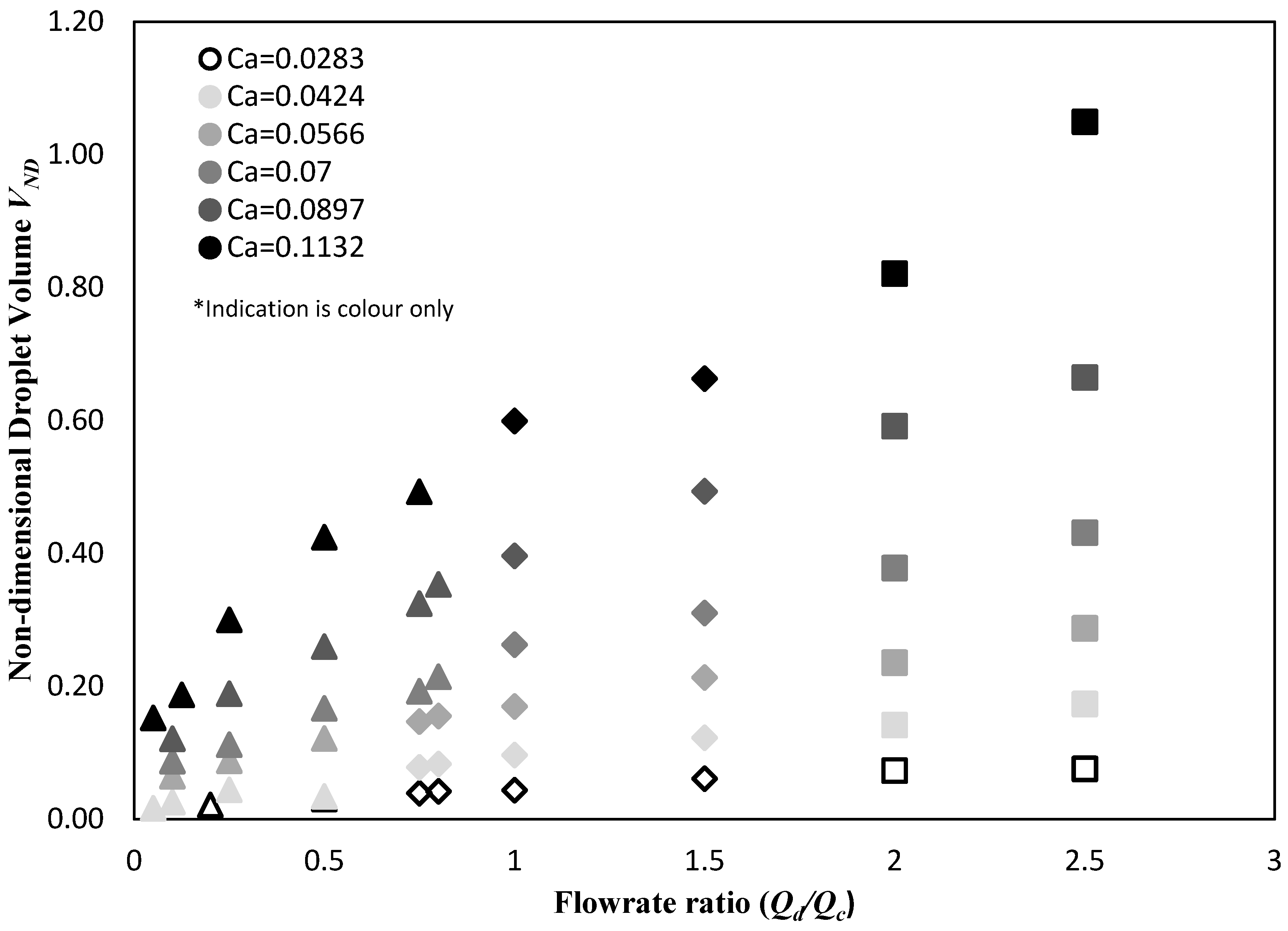
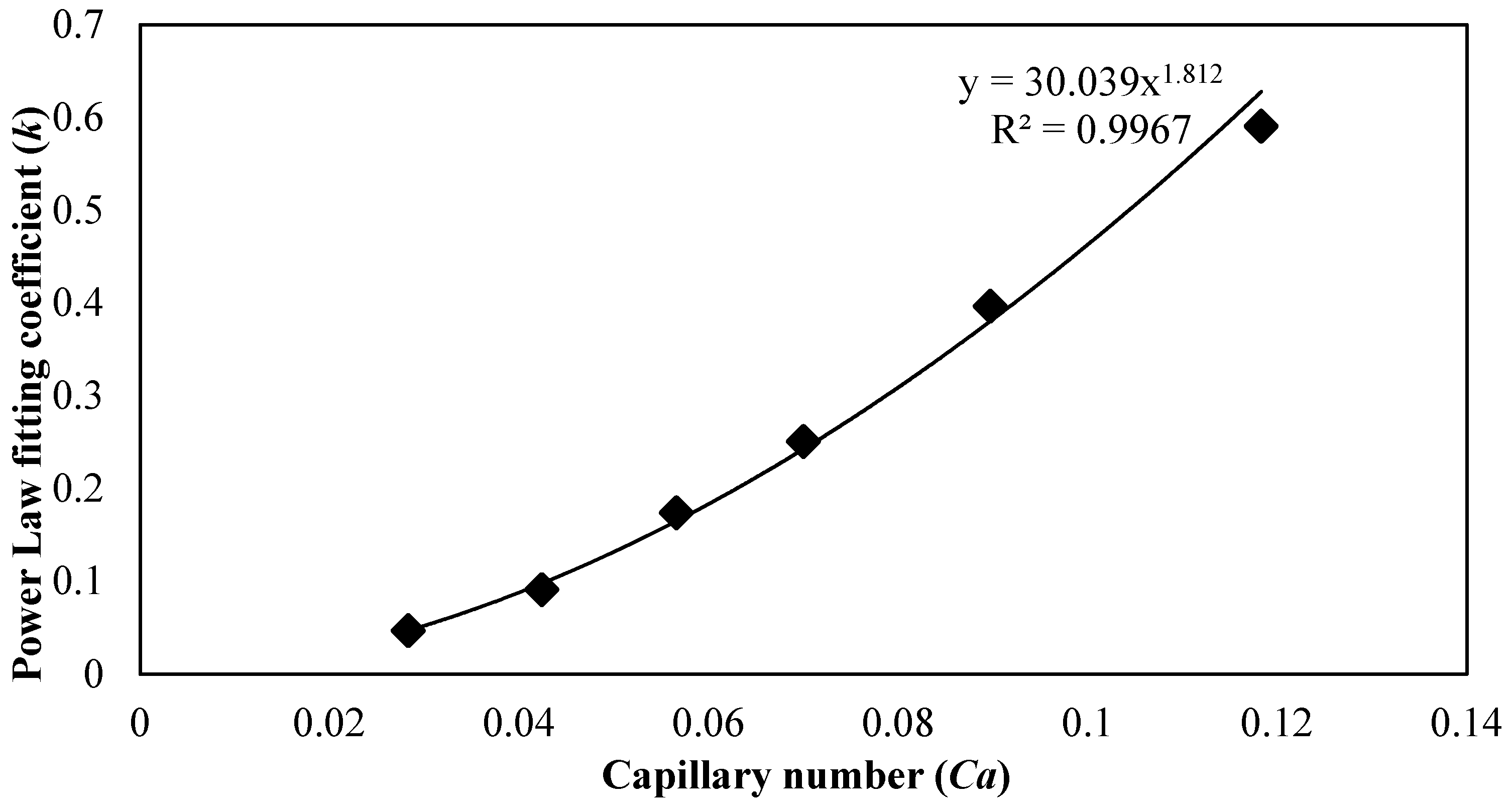
A power law dependency of the non-dimensional droplet volume on capillary number is identified by Christopher et al. [13]. They suggested that the droplet volume (V) varies with all tested capillary numbers, and they have identified a power law dependency on capillary number as follows:
V C a 1 δ
where 1 − δ = −0.316 ± 0.016. The non-dimensional volume is inversely proportional to capillary number as δ > 1. Bai et al. [7] have extended the power law dependency of the droplet size on capillary number in both squeezing and dripping regimes. However, they have reported a distinct change in the power law exponent when capillary number is increased above a critical value.
Graaf et al. [27], in their investigation of the formation of a droplet from a single pore, have proposed that the droplet formation in microfluidic T-junctions consists of two stages; the droplet growth stage, and the droplet detachment (or necking) phase. Hence, they proposed and validated a model based on the assumption that the total volume of the formed droplet consists of the sum of an initial volume term which described the growth phase and the volume increase before the droplet is being detached (necking phase) [27,28]. Steegmans et al. [29] compared several models through the utilisation of statistical analysis to evaluate the predicted volume. They have suggested that the droplet size can be controlled though the control of the geometrical characteristics of the devices (thus controlling the growth volume), or by controlling the flow rates employed (to control the detachment volume).
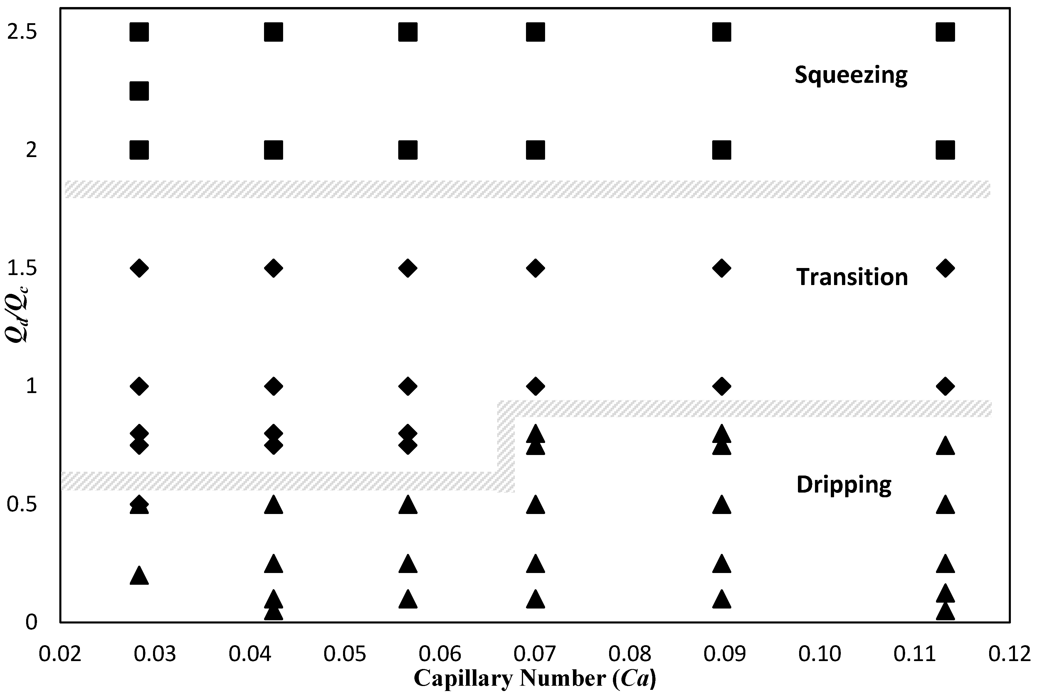
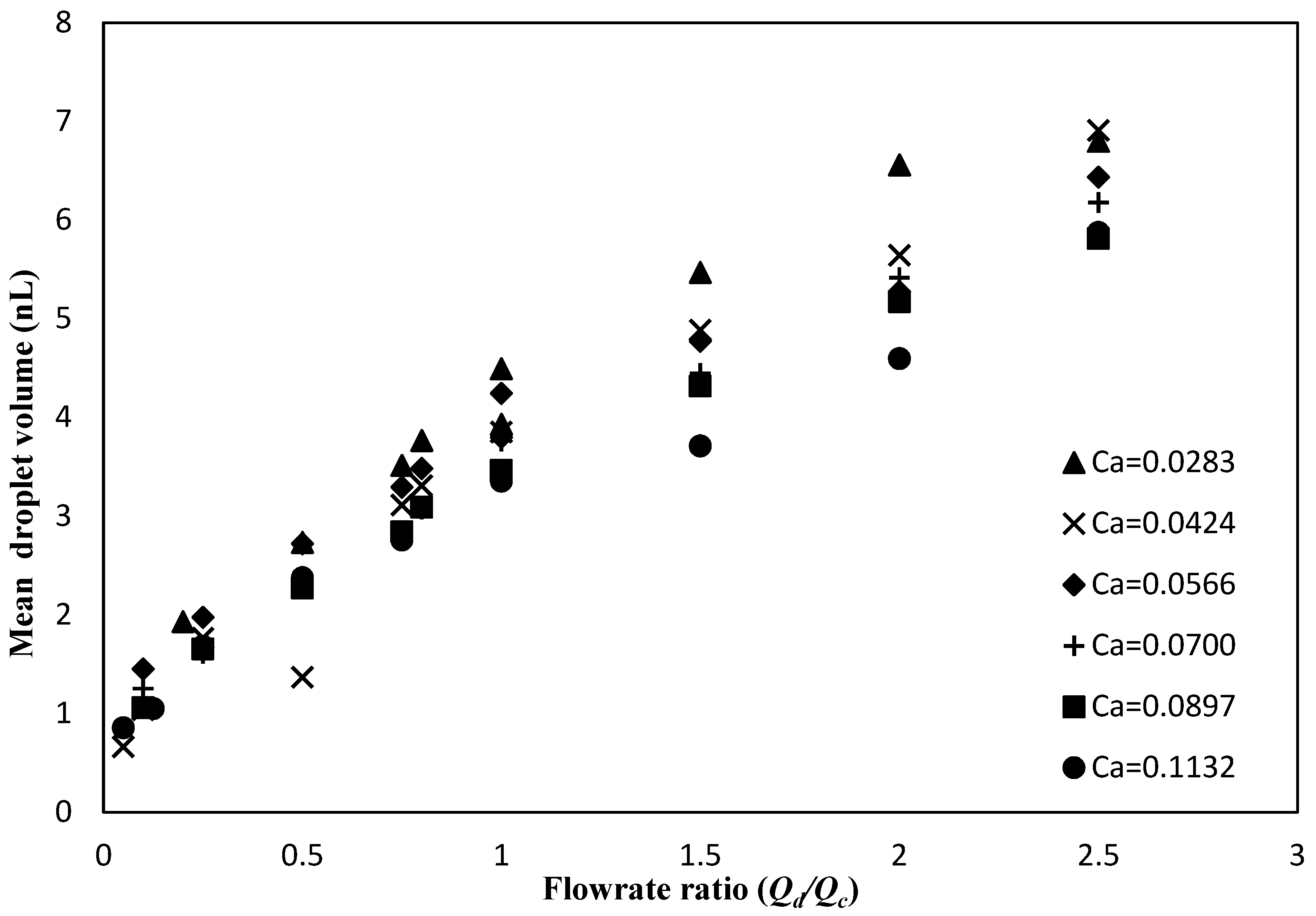
Even though the formation of droplets at T-junctions has been studied widely, it is evident that the mechanisms of droplet generation are not fully established. In addition, the effect of several parameters on the mechanism of droplet formation, and thus the droplet size, has not been fully examined. In this work, the transition between regimes at constant capillary numbers is presented, highlighting that regime transition is apparent when the flow rate ratio is varied. Finally, the effect of the flow rate ratio on the volume of droplets generated is discussed, along with a proposed model to predict the droplet volume.

2. Materials and Methods

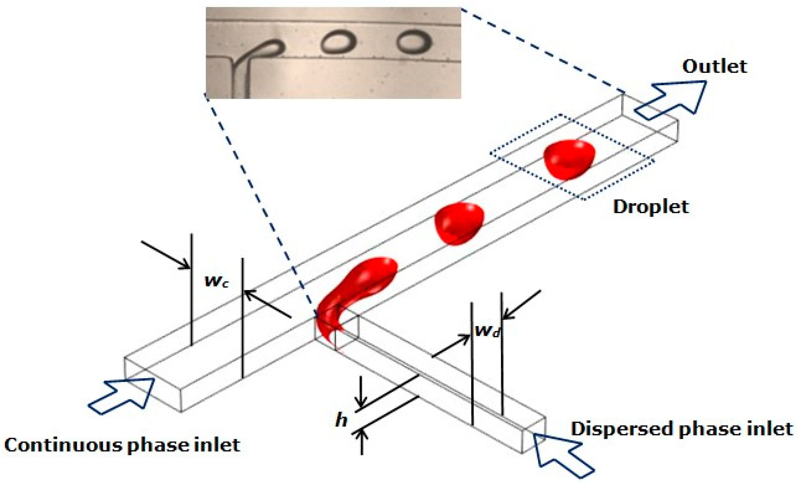
The microfluidic networks used in the present study were fabricated using soft lithography. The geometry was transferred onto a substrate coated with a negative photoresist (SU-8 2025, MicroChem, Westborough, MA, USA), and the cured substrate was used as a mould to generate microfluidic channels. Polydimethylsiloxane elastomer (PDMS, SYLGARD 184, Dow Corning, Midland, MI, USA) was used to stamp the moulds. The microchannels were fabricated by sealing the moulded pattern onto a glass slide, which was also coated with a thin layer of PDMS. A T-junction, as shown in Figure 1, was used for the experiments presented here. PDMS channels are inherently hydrophobic, with the contact angle between the three phases (PDMS, olive oil, and de-ionised water) being 120.49 ± 9.19°. The contact angle was measured using a MATLAB (MathWorks, Natick, MA, USA) code developed in house, employing an image analysis code.
In such geometries, the dispersed phase (de-ionised water) flows through the side arm, which is orthogonal to the main flow channel, where the continuous phase (Olive oil, highly refined, low acidity, Sigma Aldrich, St. Louis, MO, USA) flows through. The channel height (h) of the microfluidic network used was 76 ± 5 μm, and the width of continuous (wc) and dispersed phase (wd) channels were 212 ± 10 μm and 104 ± 10 μm respectively.
The physical properties of the liquids used were measured at room temperature (20 ± 2 °C), and the values are given in Table 1. Viscosity measurements were performed using an Ostwald viscometer (BS/U tube Viscometer) and density was measured using a densitometer (30PX Mettler Toledo, Colombus, OH, USA). Interfacial tension was determined using the pendant drop method, by dispensing a drop of de-ionised water into olive oil [8]. It should be noted that Marangoni effects were neglected due the employment of pure solutions.
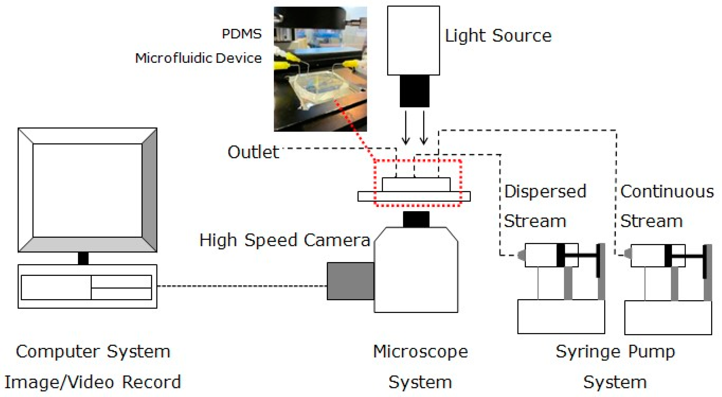
The experimental set up, as depicted in Figure 2, consisted of two infusion pumps used to deliver the continuous and the dispersed phase (AL-1000, World Precision Instruments (Hitchin, UK) and NE-1000, ProSence B.V. (Oosterhout, The Netherlands). The droplets generated were captured using a high speed camera (HotShot CC, NAC Image Technology) mounted onto an inverted microscope (GXMXDS3 VS-3, GX Microscopes, GT Vision, Suffolk, UK) at a frame rate of 500 fps.
In order to identify the transition between regimes, the percentage of the channel filled by the droplet as soon as it is detached from the dispersed phase filament was employed as a threshold. A MATLAB image analysis code was developed, where images extracted from the high speed videos were analysed. A Gaussian filter was employed to smooth the resulting image, and the edges of the droplet and the microchannels were detected through the Sobel method. The detected boundaries were traced and extracted using the built-in boundary tracing function. The distance between the edge of the droplet and the microchannel walls was calculated, after converting the pixel values to micrometers. This enabled the calculation of the percentage of the channel occupied by the emerging droplet.
A modified capillary number based on the continuous phase properties, where μc and Uc represent the dynamic viscosity and the velocity of the continuous phase, while σ denotes the interfacial tension between the two liquids [30], was employed for the purpose of this study. The interfacial force term in this case was calculated using the interfacial tension between the continuous and dispersed phase.
C a = μ c U c / σ
Experiments were performed at several constant capillary numbers ranging from 0.0283 to 0.1132. At each capillary number (thus at each continuous phase flow rate), the droplet behaviour was examined at the range of dispersed phase flow rates employed. The flow rate ratios were kept similar for each capillary number. A summary of flow rates of both the continuous and dispersed phase, as well as the flow rate ratio between the two, is presented in Table 2. Due to pump limitations, capillary numbers smaller than 0.0283 were excluded from the experimental study.
The volume of droplets generated was calculated by dividing the dispersed phase flow rate Qd with the average frequency or rate of neck collapse, as obtained from the high speed videos. The rate of the neck collapse was defined as the rate at which the dispersed phase thread thinned, before breaking up into segments. The system was allowed to stabilise for 20 minutes for each flow rate examined in this work. It is worth mentioning that the coefficient of variation (the quotient of standard deviation over the mean) of the droplet volume was below 7%. Previous work by the authors demonstrated that the droplet diameter was not indicative of the size of the droplets, as the effect of confinement is significant and cannot be neglected [31]. Experiments performed using two different microchannel networks indicated that increasing the cross-sectional area of the continuous phase channel resulted in an increase of the volume of the resulting droplets. The volume can be used as a universal indication of the size, as it is applicable for all systems and regimes [31].

3. Results

3.1. Effect of Flowrate Ratio on Regime Transition at Constant Capillary Numbers

The droplet generation mechanism and regimes were experimentally investigated and observed for a range of flow conditions. Within the parametric space examined, three different modes of droplet generation were apparent; squeezing, dripping, and the transitional regime, which was a transition between the first two. Therefore, it was essential to describe each mode in detail for clarification. For each of the three cases, a characteristic droplet pinch-off time existed. The three droplet formation modes captured during the experiments are shown in Table 3. It should be noted that in all the cases shown in Table 3, the flow rate of the continuous phase was fixed at 1 mL/h, and the dispersed phase flow rate was varied at 0.25, 1, and 2 mL/h for dripping, transition, and squeezing respectively.
To distinguish the transition between the regimes described above, as well as the intermediary flow regimes identified in this work, image analysis techniques were employed, paired with visual observations that followed regime descriptions provided in the literature [13,21]. Through image analysis techniques of the acquired microscopic images obtained at different continuous and dispersed phase flow rates, the percentage of the channel that was filled by the droplet as soon as it was detached from the dispersed phase filament was used as a threshold to identify between regimes. The threshold value selected was 80–85% of the channel width. Droplets occupying less than 80% of the channel width were considered to be generated within the dripping regime. Droplets generated occupying 80–85% of the main channel width were considered to be generated following the transitional regime. Finally, any droplets filling more than 85% of the channel, forming plugs with the characteristic ‘flat’ section that suggested elongation, were thought to be generated during the squeezing regime. These threshold values were selected in correlation to visual observations, as well as the droplet sizes that were reported for each regime. For droplets generated during dripping, the threshold value utilised was 80%, arising from the visual observation of the break-up, along with a droplet width that was smaller than the continuous phase channel width. In contrast, during the transitional regime, small plugs were prevalent, with widths larger than the continuous phase channel width blocking 80–85% of the area available for the continuous phase to flow. Finally, large plugs were formed during squeezing, with widths that were several times the width of the continuous phase channel.
At the lowest dispersed phase flow rate of 0.25 mL/h (and thus the lowest flow rate ratio), the dripping regime was prevalent. As indicated in Table 3, small droplets were sheared off before they filled the main channel cross section. Increasing the dispersed phase flow rate to 1 mL/h where the flow rate ratio between the two phases was 1, larger droplets that filled a significant proportion of the area available for the continuous phase to flow, were observed. These droplets occupied 80–85% of the main channel width, and hence they were formed during the transitional regime. As the dispersed flow rate was further increased, larger droplets were formed. These filled most of the area that was available for the continuous phase to flow, with the droplets having an elongated section. These droplets were formed with the squeezing regime. It is also worth noticing that the rate of neck collapse associated with dripping was significantly longer than the rate of neck collapse, for the transitional and squeezing regimes.
Pairing visual observations and flow rate ratios at constant capillary numbers, as given in Table 2, a flow regime map was constructed, as shown in Figure 3. Examining the flow regime map, it is clear that dripping was prevalent at lower flow rate ratios, whereas squeezing was observed at higher flow rate ratios. A transition between the two regimes was identified at flow rate ratios within the range of 1 to 2. Table 3 clearly indicated the existence of the three distinct droplet generation modes at any given capillary number. In contrast with previous work that was reported by several researchers for the identification of regime transition [2,6,13], at constant capillary numbers, both dripping and squeezing were observed at different flow rate ratios. Therefore, for the experimental observations presented in the flow regime map, the applicability of capillary number to predict the occurrence of regimes and transitions between them was questionable. As different regimes (dripping, transition, and squeezing) are apparent at constant capillary numbers when flow rate ratio is varied, the definition of regime and transition between regimes appears to be significantly affected by the flow rate ratio employed.

3.2. Effect of Flowrate Ratio on Droplet Volume

The mean droplet volumes were plotted for various flow rate ratios at constant capillary numbers in Figure 4. A wide range of capillary numbers were tested, ranging from 0.0283 to 0.1132. Nevertheless, the flow rate ratios tested ranged from 0.05 to 2.5, covering a wide parametric space. Observing Figure 4, it was apparent that for constant capillary numbers (and thus for constant continuous phase flow rate), the mean droplet volume measured increased with an increase in the flow rate ratio. Since the capillary number was kept constant, increasing the flow rate ratio in this case indicated that the dispersed phase flow rate was increased at a constant continuous phase flow rate.
When the flow rate ratio was kept constant, the average volume of droplets generated decreased as the capillary number increased (the continuous phase flow rate increased) for most of the flow rate ratios tested. This was more prominent for droplets that were generated at higher flow rate ratios (flow rate ratios over 1). Correlating the mean droplet volume with the results presented in Section 3.1, and particularly the flow pattern map, it was clear that droplets generated at flow rate ratios larger than 1 were generated in the transitional or squeezing regimes. This was attributed to the rate of neck collapse, and will be further discussed in the discussion section.

3.3. Proposed Scaling Law to Estimate the Volume of Droplets Generated

In an attempt to characterise the droplet generation mechanism and to quantify the effect of flow rate ratio on droplet volume at constant capillary numbers, dimensional analysis has been performed to form a dimensionless volume of droplets. The dimensionless volume can be expressed as a length scale (l) multiplied by different properties that govern droplet generation in a microfluidic T-junction. Equation (3) demonstrates the length scale, l, which was used to construct an equation to predict droplet volume.
l = V D A c = Volume   of   droplet Area   of   continuous   phase   channel
Equation (5) was then multiplied by ρ, which is the density of the continuous phase (kg/m3), U2 is the square of the velocity of the continuous phase (m/s), and γ is the interfacial tension between the two fluids (mN/m) to form a non-dimensional volume, as indicated in Equation (6).
V N D = ρ U 2 γ V D A c ( μ c μ d ) η
To derive the non-dimensional volume described by Equation (6), an energy balance on the emerging dispersed phase filament was considered. The term ρU2 accounts for the kinetic energy of the continuous phase that is exerted on the emerging filament. This kinetic energy of the continuous phase acts on squeezing the neck of the dispersed phase filament to detach a segment of the thread, a droplet. The term γ(Ac/VD) expresses the surface energy per unit volume of the dispersed phase filament. This surface energy has a resorting, stabilising role that opposes the dispersed phase filament break up and the detachment of a segment to form a droplet. Due to the restoring nature of this energy, it is reflected in the denominator of Equation (6). In an attempt to describe the droplet detachment, one should consider the balance between the two energy terms that are described above. When the stabilising surface energy term is overcome by the kinetic energy term, a droplet is detached. Therefore, this competition of energies was included in the proposed equation for the non-dimensional form of the volume of droplets generated. Finally, the product is multiplied by the dimensionless viscosity ratio between the viscosity of the continuous phase and the viscosity of the dispersed phase, to account for the effect of viscosity. The effect of viscosity has been proven to influence the droplet size [13,32]. The quotient of the viscosities included, highlighted the dissipation of energy in the system. The influence of the above on the droplet breakup was pivotal. The value of the exponent η was assumed to be 1 in this case, in alignment with single phase flow where the shear force is directly proportional to viscosity. However, this hypothesis needs to be tested further, with the utilisation of systems of different viscosity ratios.
The non-dimensional volume (VND) was then plotted against the flow rate ratio Qd/Qc (Figure 5) at constant capillary numbers. It was observed that the non-dimensional droplet volume increased with increasing flow rate ratio for all capillary numbers tested. Data were fitted with a power law fitting at each capillary number employed. The power law fitting parameters, along with the coefficient of determination, are tabulated in Table 4. It is noteworthy that the non-dimensional volume was calculated for all data points regardless of the observed regimes, even though most of the work that has been performed to date, points out that different scaling laws are applicable in the squeezing and dripping regimes. Therefore, different data point symbols are used to distinguish between different regimes. As demonstrated by Equation (6), the non-dimensional volume VND is proportional to a modified Weber number, and to the viscosity ratio. The Weber number is defined as We = (ρU2 lc), where ρ is the density of the continuous phase (kg/m3), U is the velocity of the continuous phase (m/s), lc is the characteristic length scale (m) (continuous phase channel width wc for this case) and γ is the interfacial tension between the two fluids (mN/m). The power law was selected as it provides the best fit for the presented data, and it is in accordance with several scaling laws that have been suggested in the literature [13,26].
V = k ( Q d Q c ) n ,
To characterise the dependence between the power law fitting coefficient k and the capillary number, the two are plotted in Figure 6. Fitting the data with a power law curve, it is clear that the power law fitting coefficient depends on the capillary number. The fitting equation displayed in Figure 6 (along with the coefficient of determination) suggests that k = 30.04 Ca1.812. As discussed earlier, due to system limitations, capillary numbers below 0.0283 could not be examined, therefore further work is required to enable the detailed characterisation of the dependency of coefficient k on the capillary number. However, it is predicted that at lower capillary numbers, the power law coefficient curve will asymptotically approach 0.
In terms of the exponent n, as observed in Table 4, it ranges between 0.49 and 0.59. The average value of the exponent is 0.52, and the standard deviation was calculated as ± 0.04. Therefore, the predicted relationship between the non-dimensional droplet volume and the capillary number is as follows.
V N D = 30.04 C a 1.812 ( Q d Q c ) 0.52
Consequently, Equation (8) is of the general form of:
V N D = K C a α ( Q d Q c ) β
where Κ, α, and β are constants of values 30.04, 1.812, and 0.52 respectively. Substituting for VND from Equation (7) in Equation (9) results in Equation (10):
V N D = ρ U 2 γ V A c ( μ c μ d ) η = K C a α ( Q d Q c ) β
Solving (10) for the dimensional droplet volume V forms Equation (11), where γ/(ρU2) is substituted by the inverse of the Weber number, multiplied by the width of the continuous phase channel wc, as indicated below:
V = K C a α ( Q d Q c ) β ( μ d μ c ) η   γ ρ U 2   A c = K C a α ( Q d Q c ) β ( μ d μ c ) η     A c w c W e
where We is the Weber number and wc is the width of the continuous phase channel. As observed in Equation (12) below, a volume term, Ac wc emerges. This volume term is postulated to be the volume of the region of the channel where necking occurs. Ac wc forms the term VI, which is substituted into the equation below:
V = K C a α W e ( μ d μ c ) η   V I   ( Q d Q c ) β

4. Discussion

4.1. Effect of Flowrate Ratio on Regime Transition at Constant Capillary Numbers

The existence of different regimes at constant capillary numbers at different flow rate ratios can be explained if the mechanism of formation is considered. The dispersed phase thread penetrates the flowing continuous phase and occupies the main channel downstream of the T-junction, before being sheared off into droplets. The interfacial tension acts on stabilising the emerging droplet, resisting pinch-off. When a droplet occupies a significant portion of the area available for the continuous phase to flow, the flow of continuous phase is restricted to thin films along the walls, resulting in an increase of the pressure upstream of the channel. Therefore, at lower flow rate ratios (when the continuous phase flow rate is larger than dispersed phase flow rate) droplets are pinched off before the dispersed phase fills the continuous phase channel. In this case, the dispersed phase flow rate is low, not permitting the ‘inflation’ of the neck before the shear stress surpasses the interfacial tension force; thus, smaller droplets are generated. At higher flow rate ratios, as the dispersed phase flow rate is larger, a larger droplet emerges before being pinched off, due to the synergistic effect of the shear stress and the pressure build-up.
Observing Table 3 in Section 3.1, it is apparent that different mechanisms of formation are distinct at different modes. Starting with the dripping regime that is observed at the lowest dispersed phase flow rate, a droplet of a diameter that is smaller than the width of the continuous phase channel is detached before filling the area that is available for the continuous phase to flow. Generally, during dripping, droplets are sheared off before they fill the channel cross-section, where the shear force exerted on the droplet is acting against the interfacial force [6]. Even though the emerging droplet does not fill the entire channel cross-section, the continuous phase flows through a narrower cross-section, exerting large shear stress on the forming droplet [1]. Thus, the pressure build-up upstream of the emerging droplet cannot be neglected, and it is expected to facilitate break up [6,13]. In contrast, at the highest dispersed phase flow rate where squeezing regime is prevalent, a droplet is detached after occupying most of the area that is available for the continuous phase to flow. The generated droplet in the squeezing regime is large, with a characteristic long flat section being apparent at pinch-off. The flow of the continuous phase is restricted at thin films between the channel walls and the interface of the droplet (which are of several widths of the main channel in size). Consequently, due to the restriction of the continuous phase, a pressure build-up upstream is expected, while the continuous phase squeezes the dispersed phase thread at the vicinity of the T-junction.
An intermediary flow regime (transitional) can be clearly identified for a range of flow rate ratios, and has been included in Table 3. The droplet occupies a significant portion (~80–85%) of the area available for the continuous phase to flow at the time of pinch-off; however, smaller droplets are generated compared to the droplets that are generated in the squeezing regime. Therefore, this intermediate regime can be characterised as the transition between the dripping and the squeezing regime. The observed behaviour is a combination of the two regimes. The emerging droplet blocks a substantial portion of the cross-sectional area of the main channel; however, a large droplet with the characteristic long flat section is not observed. In contrast, droplets larger than the droplets generated in the dripping regime emerge. The transitional regime is predominately different from the dripping and squeezing regimes, as portrayed in Table 3. Nonetheless, the transitional regime is reproducible and is sustained over time.
As described above, the flow rate ratio plays a major role on the regime transition at constant capillary numbers.

4.2. Effect of Flowrate Ratio on Droplet Volume

From Figure 4, it is concluded that the mean droplet volume plotted against the flow rate ratio at constant capillary numbers follows a similar trend for all capillary numbers tested. At constant capillary numbers, it is apparent that the mean droplet volume increases with an increasing flow rate ratio. Additionally, at constant flow rate ratios, the mean droplet volume decreases with increasing capillary number, for most of the flow rate ratios tested
This is attributed to the increase of the shear stress acting upon the dispersed phase filament, as the capillary number is proportional to the superficial velocity of the continuous phase. This effect is more apparent at higher flow rate ratios (squeezing regime) where the developing droplet restricts the area that is available for the continuous phase to flow. Consequently, this causes the continuous phase to flow through the narrow gap between the growing droplet and the channel wall as thin films, causing an increase of the upstream pressure in the main channel. The increase in the upstream pressure contributes significantly to the droplet break-up mechanism. Therefore, at lower capillary numbers (lower continuous phase flow rates) the time needed for the dispersed phase filament to fill the area that is available for the continuous phase to flow, is longer, and the increase of pressure upstream of the emerging droplets is gradual. When the flow rate of the continuous phase (therefore the superficial velocity of the continuous phase) in a given system is increased, the droplets generated are smaller, as the shear stress acting on the emerging filament increases. Increasing the flow rate of the dispersed phase (keeping the continuous phase flow rate constant) results in larger droplets, as at a given continuous phase flow rate, the emerging tip is “inflated” with larger amounts of the dispersed phase liquid. The visual observations tabulated in Table 3 indicate that as the dispersed phase flow rate is increased at a constant continuous phase flow rate, the rate of droplet generation decreases, and thus the droplet volume increases. This behaviour is attributed to the increase of the rate of filling of the dispersed phase (de-ionised water) thread, permitting most of the channel’s cross-section to be occupied, dictating a rise on the pressure acting on the neck, causing it to collapse faster (t = 0.1 s) than at lower dispersed phase flow rates (t = 0.37 s).

4.3. Proposed Scaling Law to Estimate the Volume of Droplets Generated

The volume of droplets generated in a microfluidic T-junction appears to be affected by several parameters as it emerges from Equation (12) in Section 3.3. The volume of the resulting droplets demonstrates a power law dependency on the capillary number, with the exponent α having an empirical value, and the flow rate ratio raised at a power β, where β also has an empirical value. Additionally, the volume is proportional to the viscosity ratio. Nevertheless, a volume term is included in the proposed scaling law. This volume is proportional to the area where the dispersed phase filament penetrates the continuous phase flow and grows before pinch-off. It is postulated that this volume can be defined as the volume that a droplet occupies before detaching. It is also demonstrated that increasing the interfacial tension of the system, and thus the restoring interfacial forces, results in increasing the resistance to droplet generation, and thus in the generation of larger droplets. The droplet size is inversely proportional to the inertial forces associated with the system.
On the effect of inertia on the droplet volume, it is concluded that increasing the inertial force applied on the emerging dispersed phase filament results in decreasing the volume of the generated droplets. This reflected by the fact that droplet volume is inversely proportional to the Weber number. However, in an attempt to investigate the effect of inertial forces on the droplet volume, the quotient of the capillary number over the Weber number is substituted with the Reynolds number. The Reynolds number is defined as Re = (ρUlc)/μ, where ρ is the density of the continuous phase (kg/m3), U is the velocity of the continuous phase (m/s), lc is the characteristic length scale (m), and μ is the dynamic viscosity (kg/ms). The proposed scaling law can then be expressed as follows, where the exponent α > 1.
V = K   C a α 1 R e ( μ d μ c   ) η   V I   ( Q d Q c ) β
Therefore, as the Reynolds number emerges on the denominator of the proposed scaling law, it is clear that the effect of the inertial force on the droplet generation mechanism should not be neglected. Nevertheless, it should be taken into account that the Reynolds number and the capillary number are of the same order of magnitude for the system employed in this study. Previous scaling laws proposed by several researchers [3,14,23,24] have proposed that a unique scaling mechanism should be attributed to different regimes; therefore, two main types of scaling laws have emerged. The scaling law presented in this work is compared to the scaling law that is proposed by Christopher et al. [13]. They have concluded that the non-dimensional volume is inversely proportional to the capillary number, which is in contrast with the proposed scaling law presented here. It should be taken into account that the volume that is proposed by Christopher et al. [13] is non-dimensionalised using the channel geometrical characteristics.
Regarding the volume (VI) term that is included in Equation (13), the scaling laws proposed by different research groups are expressed in respect of a volume term. van Steijn et al. [24], working in the squeezing regime, indicated that the predicted volume is the sum of the volume of the droplet during the ‘filling’ stage, which corresponds to the volume of the area that is occupied by the thread when the emerging droplet is approaching the walls of the continuous phase channel, and the volume that is acquired during squeezing where the emerging droplet grows downstream. It should be taken into consideration that the presented scaling law is a modification of the scaling law presented by Garstecki et al. [3], and this is applicable at the squeezing regime. An analogous approach has been presented in Yeom and Lee [25], as well as Steegmans et al. [29], where the predicted volume is affected by the volume of the ‘primary’ droplet section that penetrates the continuous phase flow, and the volume that is proportional to the amount of dispersed phase fluid that is dispensed during the detachment of the droplet. Consequently, it is clear that the size of the generated droplets is affected by the volume that is available for the emerging filament to occupy, before it is detached. As the emerging thread grows in the continuous phase channel, it restricts the area that is available for the continuous phase to flow, as demonstrated previously. Therefore, the size of the microfluidic geometry that is utilised, affects the size of generated droplets, and it is postulated that the droplet sizes are independent of the shape of the cross-section.

5. Conclusions

In the present study, the effect of the flow rate ratio at constant capillary numbers has been demonstrated. The transition between squeezing and dripping, as well as a transition regime was observed at constant capillary numbers with varying flow rate ratios. A flow regime map was constructed based on the droplet formation mechanisms observed. Dripping is predominant at lower flow rate ratios, whereas squeezing is observed at higher flow rate ratios. A transition between the two regimes is apparent at flow rate ratios within the range of 1 to 2, identifying the parametric space where a transitional regime is observed. This observation is in contrast with previous work found in the literature, where the identification of regime transition was singularly based on a capillary number that was inherently system-specific. Consequently, for the experimental observations presented in the flow regime map, the applicability of the capillary number alone to predict the occurrence of regimes and transition between them is ambiguous. The presented model is derived from an energy balance on the emerging dispersed phase filament entering the continuous phase channel where the continuous phase flows. The non-dimensional volume of a droplet forming in a microfluidic T-junction is related to the capillary number, the Weber number, and the viscosity and the flow rate ratio.

Author Contributions

Conceptualization, B.H. and K.L.; Methodology, B.H. and K.L.; Investigation, K.L.; Resources, B.H., K.L., V.-L.W.; Writing—Original Draft Preparation, K.L.; Writing—Review & Editing, B.H., V.-L.W.; Supervision, B.H.

Funding

K.L. was supported by the Dean of Engineering Scholarship awarded by the Faculty of Engineering, The University of Nottingham during the PhD research candidacy. V.-L.W. was supported by the University of Nottingham’s Malaysia Intercampus Doctoral Award Scheme (MIDAS).

Conflicts of Interest

The authors declare no conflict of interest.

References

  1. Thorsen, T.; Roberts, R.W.; Arnold, F.H.; Quake, S.R. Dynamic pattern formation in a vesicle-generating microfluidic device. Phys. Rev. Lett. 2001, 86, 4163. [Google Scholar] [CrossRef] [PubMed]
  2. Garstecki, P.; Ganan-Calvo, A.M.; Whitesides, G.M. Formation of bubbles and droplets in microfluidic systems. Tech. Sci. 2005, 53, 361–372. [Google Scholar]
  3. Garstecki, P.; Fuerstman, M.J.; Stone, H.A.; Whitesides, G.M. Formation of droplets and bubbles in a microfluidic T-junction—Scaling and mechanism of break-up. Lab Chip 2006, 6, 437–446. [Google Scholar] [CrossRef] [PubMed]
  4. Zhao, C.X.; Middelberg, A.P. Two-phase microfluidic flows. Chem. Eng. Sci. 2011, 66, 1394–1411. [Google Scholar] [CrossRef]
  5. Nisisako, T.; Torii, T.; Higuchi, T. Novel microreactors for functional polymer beads. Chem. Eng. J. 2004, 101, 23–29. [Google Scholar] [CrossRef]
  6. De Menech, M.; Garstecki, P.; Jousse, F.; Stone, H.A. Transition from squeezing to dripping in a microfluidic T-shaped junction. J. Fluid Mech. 2008, 595, 141–161. [Google Scholar] [CrossRef]
  7. Bai, L.; Fu, Y.; Zhao, S.; Cheng, Y. Droplet formation in a microfluidic T-junction involving highly viscous fluid systems. Chem. Eng. Sci. 2016, 145, 141–148. [Google Scholar] [CrossRef]
  8. Chiarello, E.; Gupta, A.; Mistura, G.; Sbragaglia, M.; Pierno, M. Droplet breakup driven by shear thinning solutions in a microfluidic T-junction. Phys. Rev. Fluids 2017, 2, 123602. [Google Scholar] [CrossRef]
  9. Roumpea, E.; Chinaud, M.; Angeli, P. Experimental investigations of non-Newtonian/Newtonian liquid-liquid flows in microchannels. AIChE J. 2017, 63, 3599–3609. [Google Scholar] [CrossRef] [Green Version]
  10. Tice, J.D.; Lyon, A.D.; Ismagilov, R.F. Effects of viscosity on droplet formation and mixing in microfluidic channels. Anal. Chim. Acta 2004, 507, 73–77. [Google Scholar] [CrossRef] [Green Version]
  11. Adamson, A.W.; Gast, A.P. Physical Chemistry of Surfaces, 6th ed.; Wiley: New York, NY, USA, 1997; pp. 4–35. ISBN 978-0-471-14873-9. [Google Scholar]
  12. Baroud, C.N.; Gallaire, F.; Dangla, R. Dynamics of microfluidic droplets. Lab on a Chip 2010, 10, 2032–2045. [Google Scholar] [CrossRef] [PubMed]
  13. Christopher, G.F.; Noharuddin, N.N.; Taylor, J.A.; Anna, S.L. Experimental observations of the squeezing-to-dripping transition in T-shaped microfluidic junctions. Phys. Rev. E 2008, 78, 036317. [Google Scholar] [CrossRef] [PubMed]
  14. Xu, J.H.; Li, S.W.; Tan, J.; Luo, G.S. Correlations of droplet formation in T-junction microfluidic devices: From squeezing to dripping. Microfluid. Nanofluid. 2008, 5, 711–717. [Google Scholar] [CrossRef]
  15. Fu, T.; Ma, Y.; Funfschilling, D.; Zhu, C.; Li, H.Z. Squeezing-to-dripping transition for bubble formation in a microfluidic T-junction. Chem. Eng. Sci. 2010, 65, 3739–3748. [Google Scholar] [CrossRef]
  16. Glawdel, T.; Elbuken, C.; Ren, C.L. Droplet formation in microfluidic T-junction generators operating in the transitional regime. I. Experimental observations. Phys. Rev. E 2012, 85, 016322. [Google Scholar] [CrossRef] [PubMed]
  17. Glawdel, T.; Elbuken, C.; Ren, C.L. Droplet formation in microfluidic T-junction generators operating in the transitional regime. II. Modeling. Phys. Rev. E 2012, 85, 016323. [Google Scholar] [CrossRef] [PubMed]
  18. Zagnoni, M.; Anderson, J.; Cooper, J.M. Hysteresis in multiphase microfluidics at a T-Junction. Langmuir 2010, 26, 9416–9422. [Google Scholar] [CrossRef] [PubMed]
  19. Gupta, A.; Murshed, S.S.; Kumar, R. Droplet formation and stability of flows in a microfluidic T-junction. Appl. Phys. Lett. 2009, 94, 164107. [Google Scholar] [CrossRef]
  20. Gupta, A.; Kumar, R. Effect of geometry on droplet formation in the squeezing regime in a microfluidic T-junction. Microfluid. Nanofluid. 2010, 8, 799–812. [Google Scholar] [CrossRef]
  21. Liu, H.; Zhang, Y. Droplet formation in a T-shaped microfluidic junction. J. Appl. Phys. 2009, 106, 034906. [Google Scholar] [CrossRef] [Green Version]
  22. Guillot, P.; Colin, A. Stability of parallel flows in a microchannel after a T junction. Phys. Rev. E 2005, 72, 066301. [Google Scholar] [CrossRef] [PubMed]
  23. Xu, J.H.; Li, S.W.; Tan, J.; Wang, Y.J.; Luo, G.S. Preparation of highly monodisperse droplet in a T-junction microfluidic device. AIChE J. 2006, 52, 3005–3010. [Google Scholar] [CrossRef]
  24. Van Steijn, V.; Kleijn, C.R.; Kreutzer, M.T. Predictive model for the size of bubbles and droplets created in microfluidic T-junctions. Lab Chip 2010, 10, 2513–2518. [Google Scholar] [CrossRef] [PubMed]
  25. Yeom, S.; Lee, S.Y. Size prediction of drops formed by dripping at a micro T-junction in liquid–liquid mixing. Exp. Therm. Fluid Sci. 2011, 35, 387–394. [Google Scholar] [CrossRef]
  26. Zhang, Y.; Fan, J.; Wang, L. Formation of nanoliter droplets in a confined microfluidic T-shaped junction: Formation time and droplet volume. Curr. Nanosci. 2010, 5, 519–526. [Google Scholar] [CrossRef]
  27. Van der Graaf, S.; Steegmans, M.L.J.; Van Der Sman, R.G.M.; Schroën, C.G.P.H.; Boom, R.M. Droplet formation in a T-shaped microchannel junction: A model system for membrane emulsification. Colloids Surf. A Physicochem. Eng. Asp. 2005, 266, 106–116. [Google Scholar] [CrossRef]
  28. Van der Graaf, S.; Nisisako, T.; Schroen, C.G.P.H.; Van Der Sman, R.G.M.; Boom, R.M. Lattice Boltzmann simulations of droplet formation in a T-shaped microchannel. Langmuir 2006, 22, 4144–4152. [Google Scholar] [CrossRef] [PubMed]
  29. Steegmans, M.L.J.; Schroën, C.G.P.H.; Boom, R.M. Generalised insights in droplet formation at T-junctions through statistical analysis. Chem. Eng. Sci. 2009, 64, 3042–3050. [Google Scholar] [CrossRef]
  30. Berthier, J.; Silberzan, P. Microfluidcs for Biotechnology, 2nd ed.; Artec House: London, UK; pp. 39–41.
  31. Loizou, K.; Thielemans, W.; Hewakandamby, B.N. Effect of Geometry on Droplet Generation in a Microfluidic T-Junction. In Proceedings of the ASME 2013 Fluids Engineering Division Summer Meeting, Incline Village, NV, USA, 7–11 July 2013; American Society of Mechanical Engineers: New York, NY, USA; p. V002T21A003. [Google Scholar] [CrossRef]
  32. Li, X.B.; Li, F.C.; Yang, J.C.; Kinoshita, H.; Oishi, M.; Oshima, M. Study on the mechanism of droplet formation in T-junction microchannel. Chem. Eng. Sci. 2012, 69, 340–351. [Google Scholar] [CrossRef]
Figure 1. Schematic representation of the channel geometry and droplet formation.
Inventions 03 00054 g001
Figure 2. Experimental set up diagram depicting the microscope system utilized, connected to a high speed camera that enabled recording of the observed behaviour. Two syringe pumps were employed to drive the flows.
Inventions 03 00054 g002
Figure 3. Flow regime map at constant capillary numbers where triangles correspond to dripping, diamonds to transition, and rectangles to squeezing. Shaded regions on the graph indicate the postulated transition between regimes.
Inventions 03 00054 g003
Figure 4. Mean droplet volume at constant capillary numbers plotted against the flow rate ratio. It is observed that increasing the flow rate results in increases in the droplet volumes measured. At constant flow rate ratios, the mean volumes of the droplets decrease with increasing capillary number for most flow rate ratios tested.
Inventions 03 00054 g004
Figure 5. Non-dimensional droplet volume plotted against the flow rate ratio between the dispersed phase flow rate and the continuous phase flow rate for different capillary numbers. The colour legend of this graph indicates the colour scheme used for the different capillary numbers. Triangles correspond to dripping, diamonds to transition, and rectangles to squeezing.
Inventions 03 00054 g005
Figure 6. Power law fitting coefficient (k) plotted against capillary number.
Inventions 03 00054 g006
Table 1. Physical properties of fluids.
FluidViscosity (mPas)Density (kg/m3)Interfacial Tension (mN/m)
Olive oil68.10 ± 0.67910.55 ± 0.49520.74 ± 0.47
De-ionised water1.21 ± 0.054997.32 ± 0.045
Table 2. Summary of experiments.
Capillary NumberContinuous Phase Flowrate Qc (mL/h)Dipsersed Phase Flowrate Qd (mL/h)Flowrate Ratio (Qd/Qc)
0.02830.50.10.2
0.250.5
0.3750.75
0.40.8
0.51
0.751.15
12
1.252.25
1.52.5
0.04240.750.03750.05
0.0750.1
0.18750.25
0.3750.5
0.56250.75
0.60.8
0.7501
1.1251.5
1.52
1.8752.5
0.056610.10.1
0.250.25
0.50.5
0.750.75
0.80.8
11
1.51.5
22
2.52.5
0.071.250.1250.1
0.31250.25
0.6250.5
0.93750.75
10.8
1.251
1.8751.5
2.52
3.1252.5
0.08971.60.160.1
0.40.25
0.80.5
1.20.75
1.280.8
1.61
2.41.5
3.22
42.5
0.113220.10.05
0.250.125
0.50.25
10.5
1.50.75
21
31.5
42
52.5
Table 3. Timescale of droplet generation during dripping, squeezing, and the transitional regime at a constant capillary number Ca = 0.0566. The dispersed phase flow rate (Qd) is varied, while the continuous phase flow rate (Qc) is kept constant.
RegimeInitialThread Penetrating Continuous Phase FlowDroplet Growing DownstreamDroplet Pinch-off
DrippingInventions 03 00054 i001Inventions 03 00054 i002Inventions 03 00054 i003Inventions 03 00054 i004
Qd = 0.25 mL/ht = 0 st = 0.1 st = 0.2 st = 0.37 s
TransitionalInventions 03 00054 i005Inventions 03 00054 i006Inventions 03 00054 i007Inventions 03 00054 i008
Qd = 1 mL/ht = 0 st = 0.04 st = 0.12 st = 0.18 s
SqueezingInventions 03 00054 i009Inventions 03 00054 i010Inventions 03 00054 i011Inventions 03 00054 i012
Qd = 2 mL/ht = 0 st = 0.04 st = 0.06 st = 0.1 s
Table 4. Power law fitting parameters.
Capillary NumberCoefficient (k)Exponent (n)Coefficient of Determination (R2)
0.02830.04720.52860.985
0.04240.09110.58680.933
0.05660.17400.46050.990
0.07000.25100.51550.977
0.08970.39680.53380.997
0.11830.59100.49030.984

