An Application-Oriented Design Method for Networked Driving Simulation

 ,
,
Abstract
:
1. Introduction
2. Problem Description
3. State of the Art
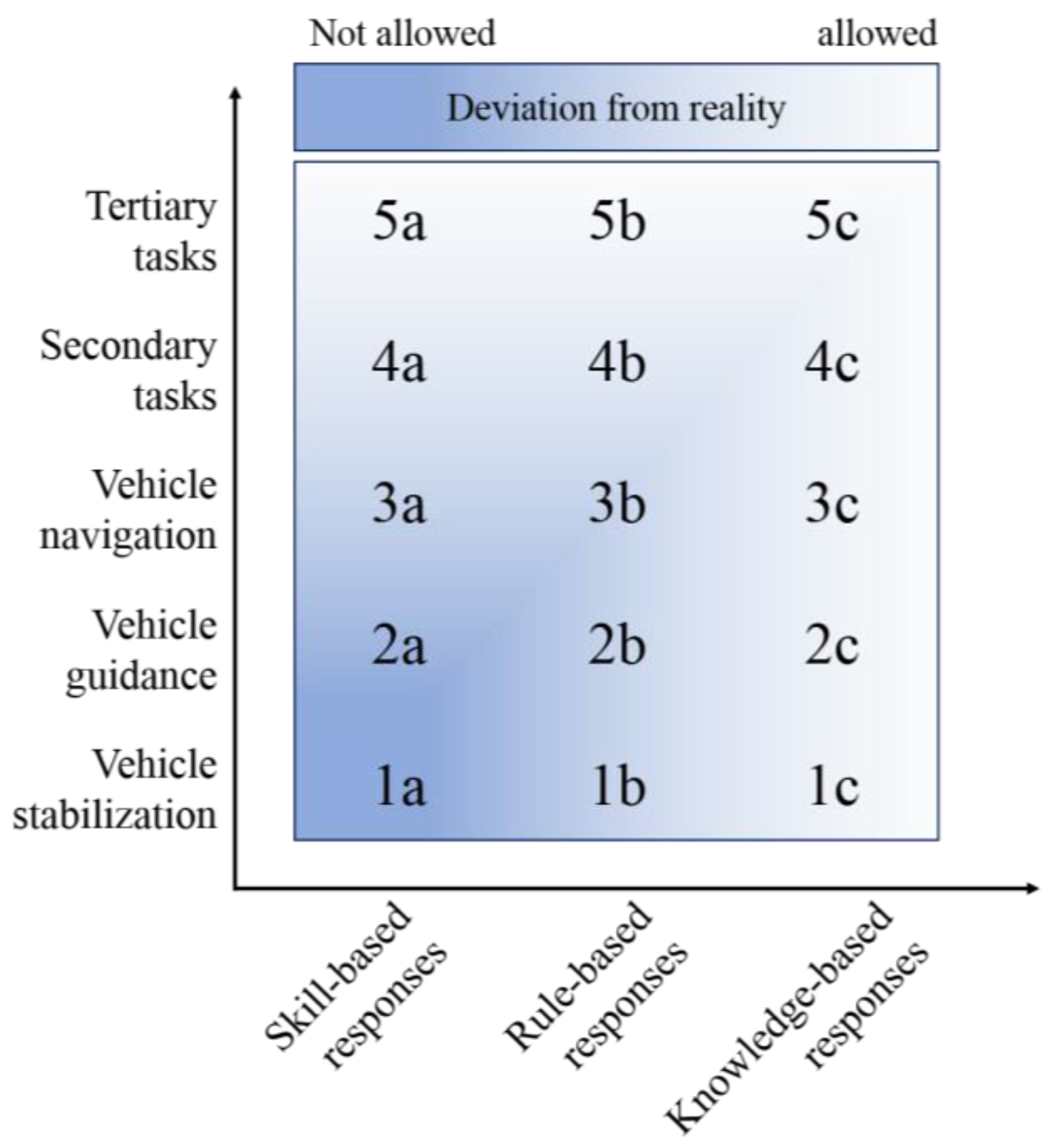
3.1. Determining Necessary Fidelity Levels of Driving Simulators
3.2. Configuring Driving Simulation Environments
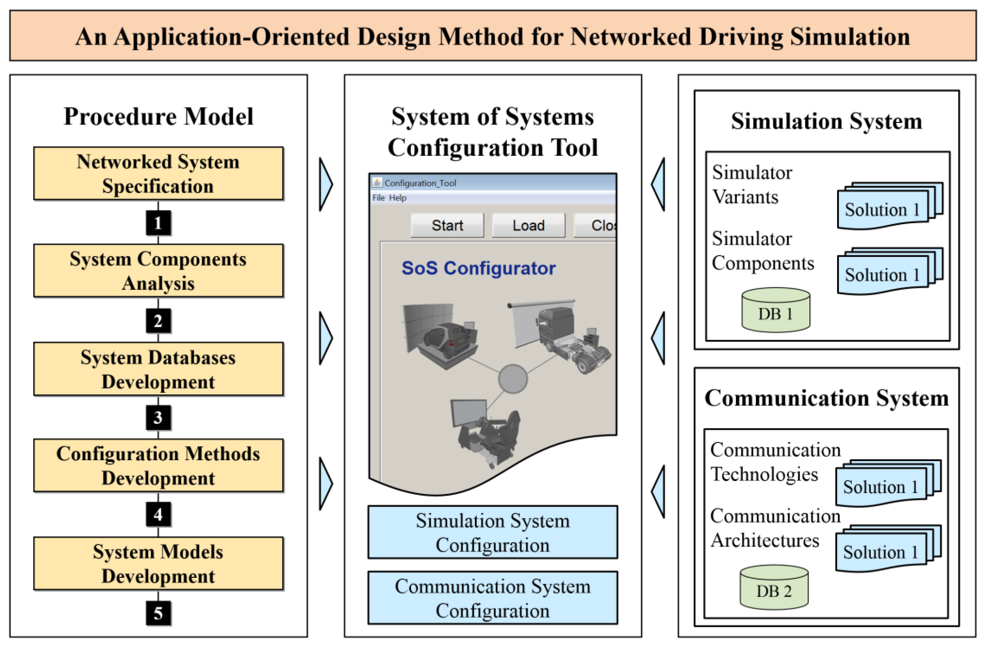
4. Development Methodology
- Procedure modelThe procedure includes the necessary development phases that are arranged in a specific hierarchy towards the design of multidisciplinary system models for platforms of networked driving simulation. Each development phase contains a set of specific tasks, which shall be carried out in order to obtain the phase objectives. The procedure model specifies the methods and approaches used in each task. Moreover, the procedure model reveals the results of each individual phase. This work is concerned with the comprehensive description of the procedure model and its phases.
- SoS configuration softwareThe SoS configuration software embeds the methods and approaches of the procedure model to generate application-oriented system models. The SoS configuration software guides non-expert system users in a sequential process to achieve the end objective. Non-expert users can be operators or domain-specific experts. They do not have to acquire deep multidisciplinary knowledge in order to use the SoS configuration software for system model design and generation. A comprehensive description of the design of the SoS configuration software is beyond the scope of this work. The design concepts of an analogous software tool are discussed thoroughly in Reference [18].
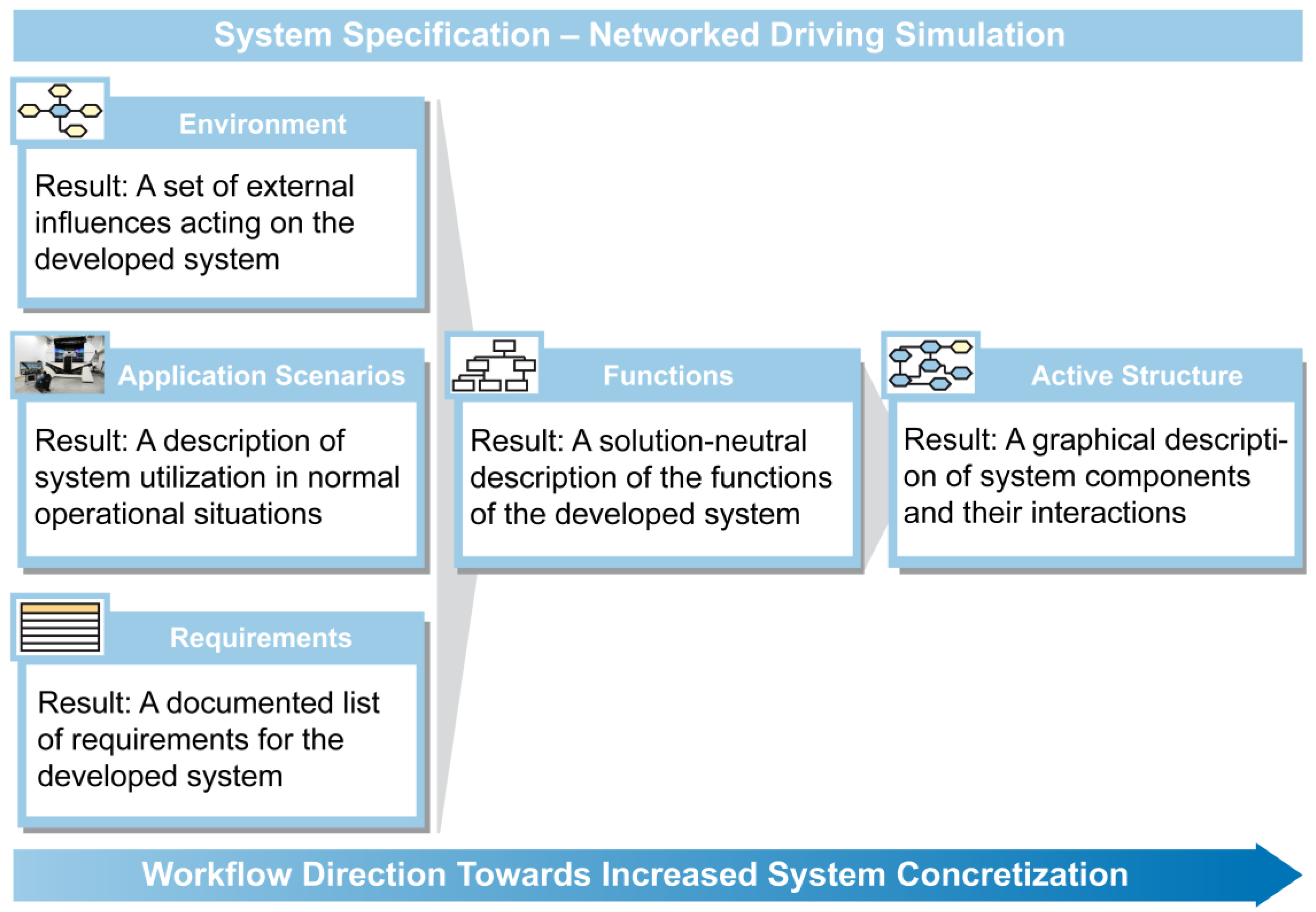
4.1. Networked System Specification
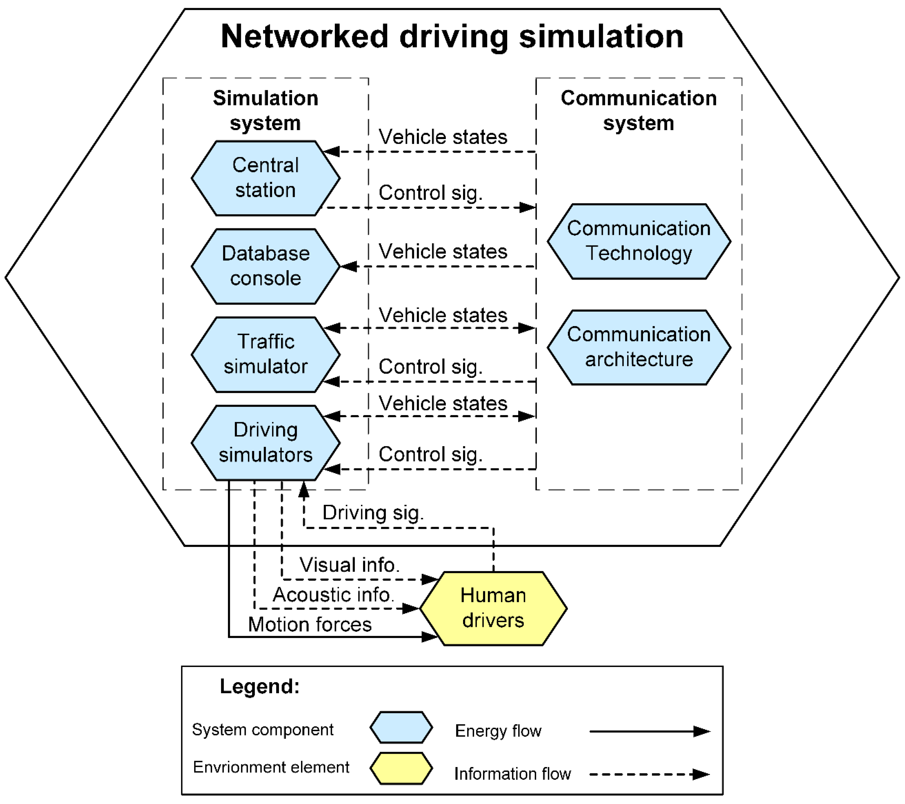
4.1.1. CONSENS Workflow for Networked Driving Simulation
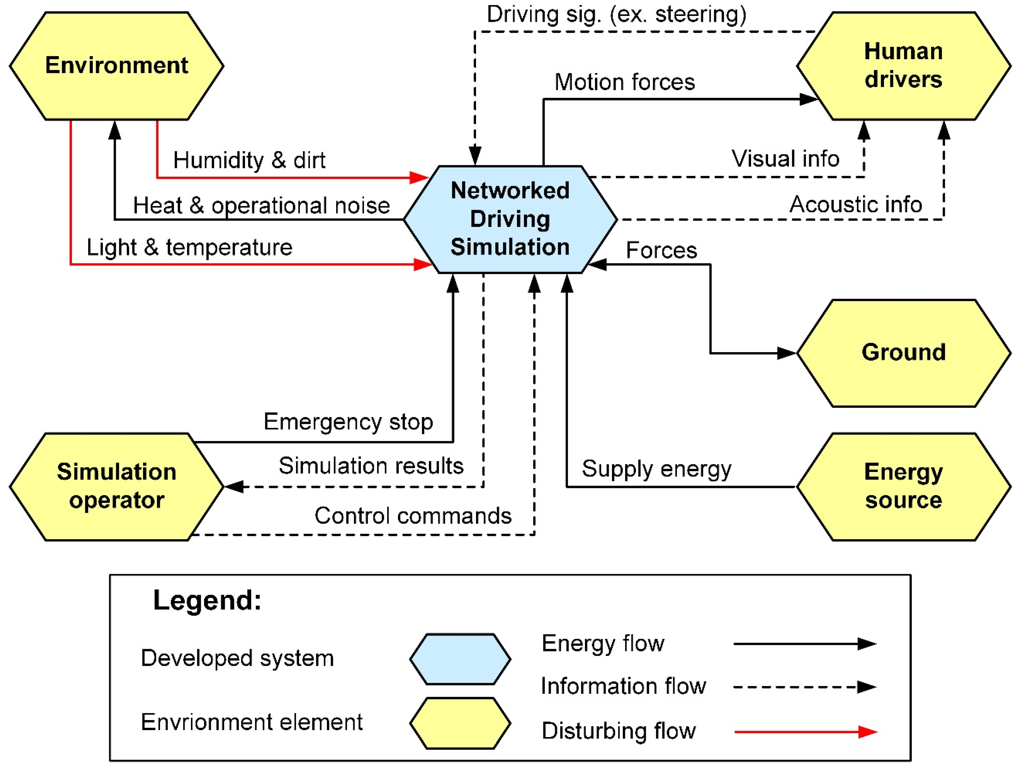
4.1.2. Identify Environment
- DriversHuman drivers represent a crucial environment element. They use the input devices within the driving platforms of the participating driving simulators to control a simulated vehicle in a virtual environment. The main input signals are: acceleration pedal position, brake pedal position, gear selector position, and steering wheel angle. The drivers receive feedback from their driving simulators in the form of motion or vibration, as well as visual and acoustic information. Basically, the motions and vibrations are generated by the eventually utilized motion platforms. In addition, some input devices, such as active steering wheels, can deliver relative motions to the drivers. The visual feedback is represented with virtual scenes displayed to the drivers via the visualization systems. The acoustic feedback is delivered via the acoustic systems as sound effects that accompany the 3D models. The visual and acoustic signals are generated often together by the visualization software.
- Simulation operatorThis can be a technician or a laboratory engineer, who is responsible for the general operation of the facility of networked driving simulation. Eventually, the simulation operator can be a domain-specific engineer or developer, who conducts some experiments using the networked driving simulation facility. The simulation operator can control the scenario by setting some simulation parameters. The networked driving simulation system returns simulation signals for monitoring purposes.
- Energy sourceThis can be a wall outlet that provides electrical energy to the constituent systems and building components of the networked driving simulation system. Eventually, some components may require power supplies to convert the electrical power of the wall outlet to the levels suitable for their circuitry.
- GroundThis is the physical base of the networked driving simulation system. Dynamic forces occur between the ground and the networked driving simulation system as actions and reactions, especially when the participating driving simulators are equipped with motion platforms.
- EnvironmentThe surrounding environment affects the networked driving simulation system through disturbing influences, such as humidity, dirt, light, and temperature. The networked driving simulation system affects the surrounding environment through the produced heat and operation noise.
4.1.3. Define Application Scenarios
4.1.4. Derive Requirements
4.1.5. Deduce Functions
4.1.6. Build Active Structure
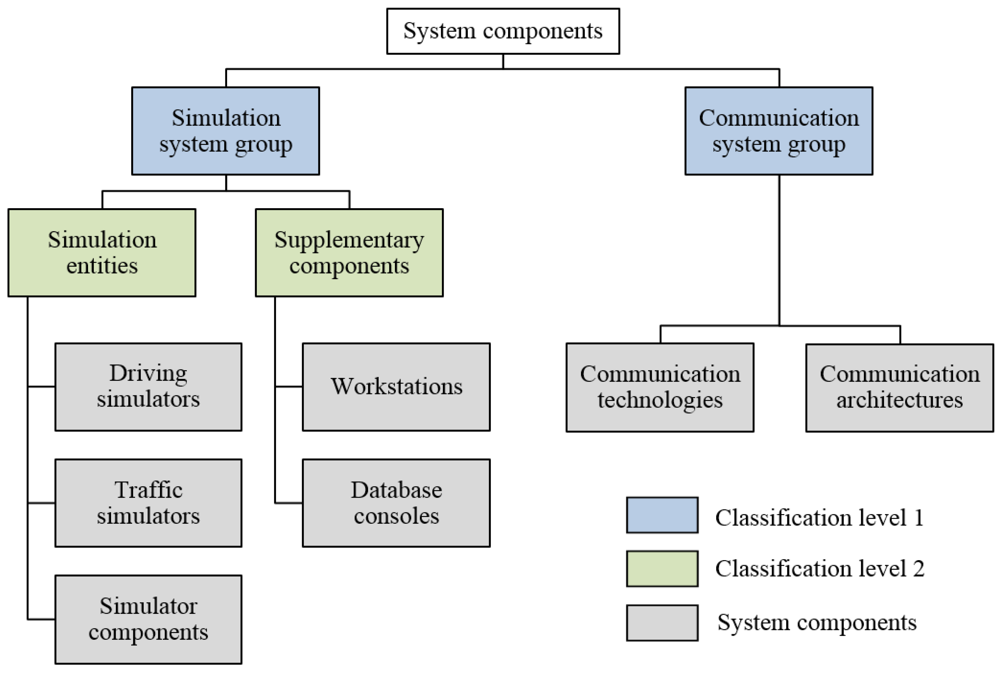
4.2. System Components Analysis
4.2.1. Identify System Components
4.2.2. Describe System Components
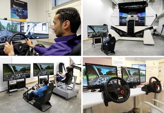
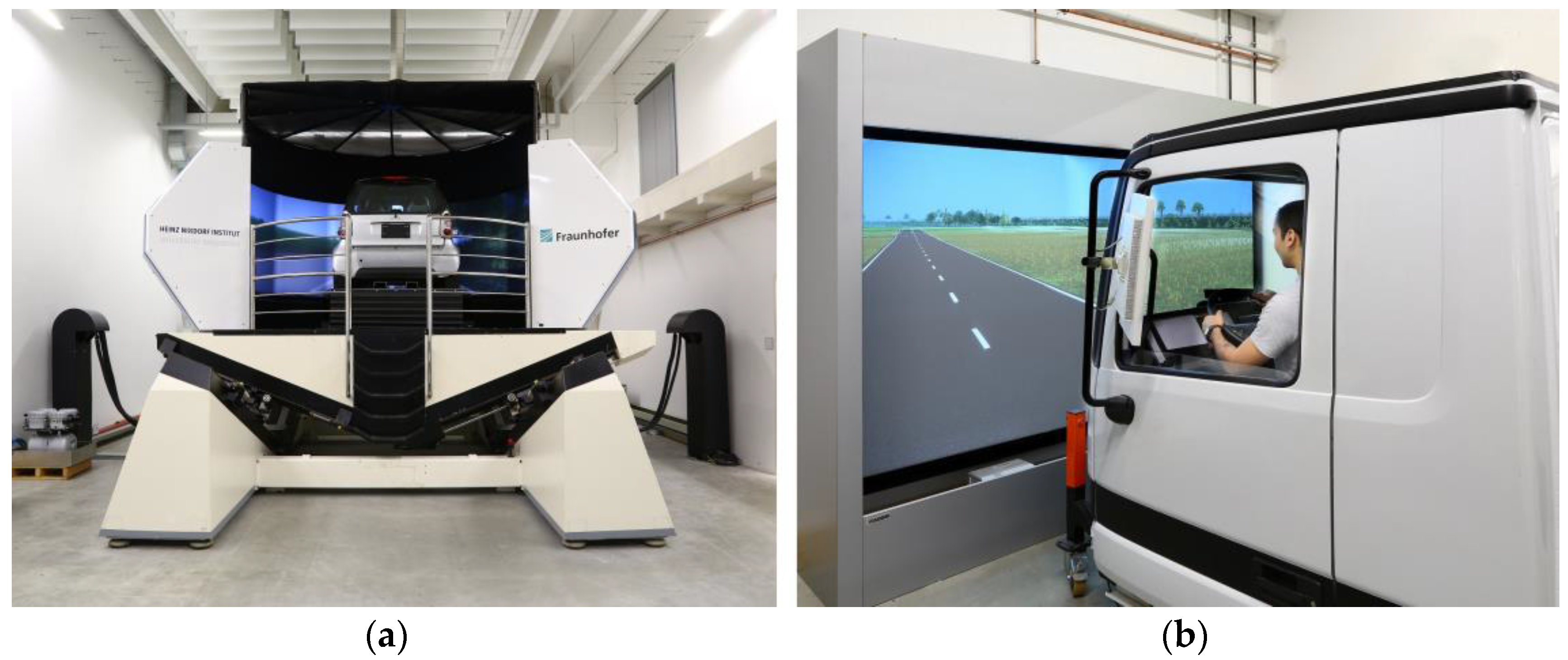
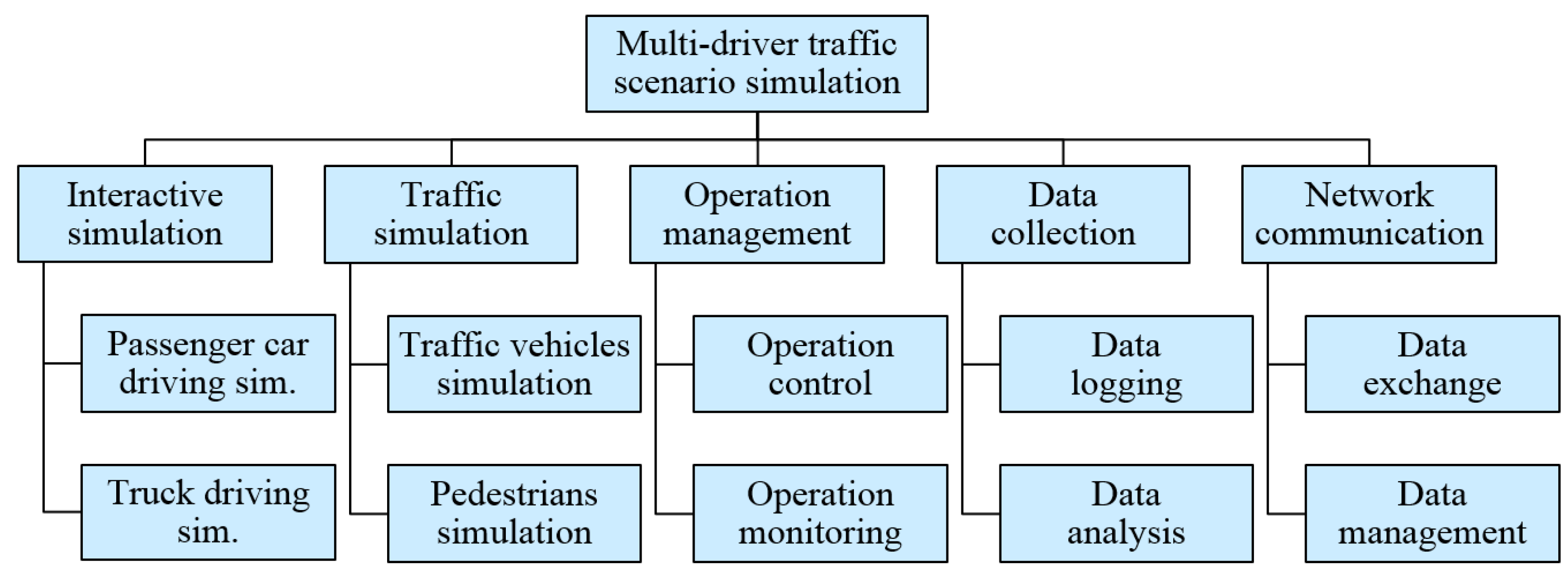
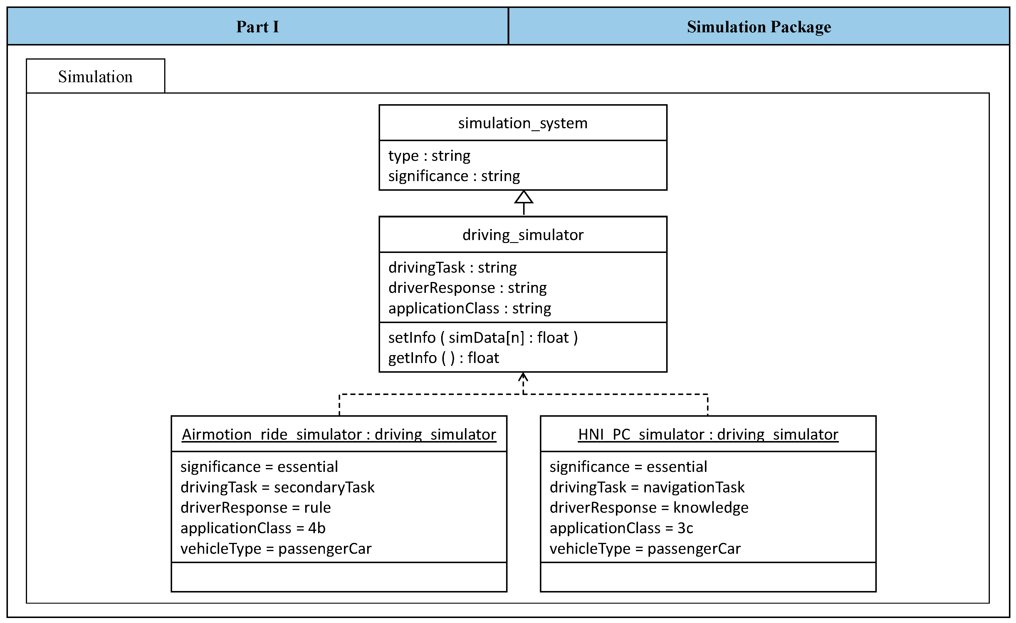
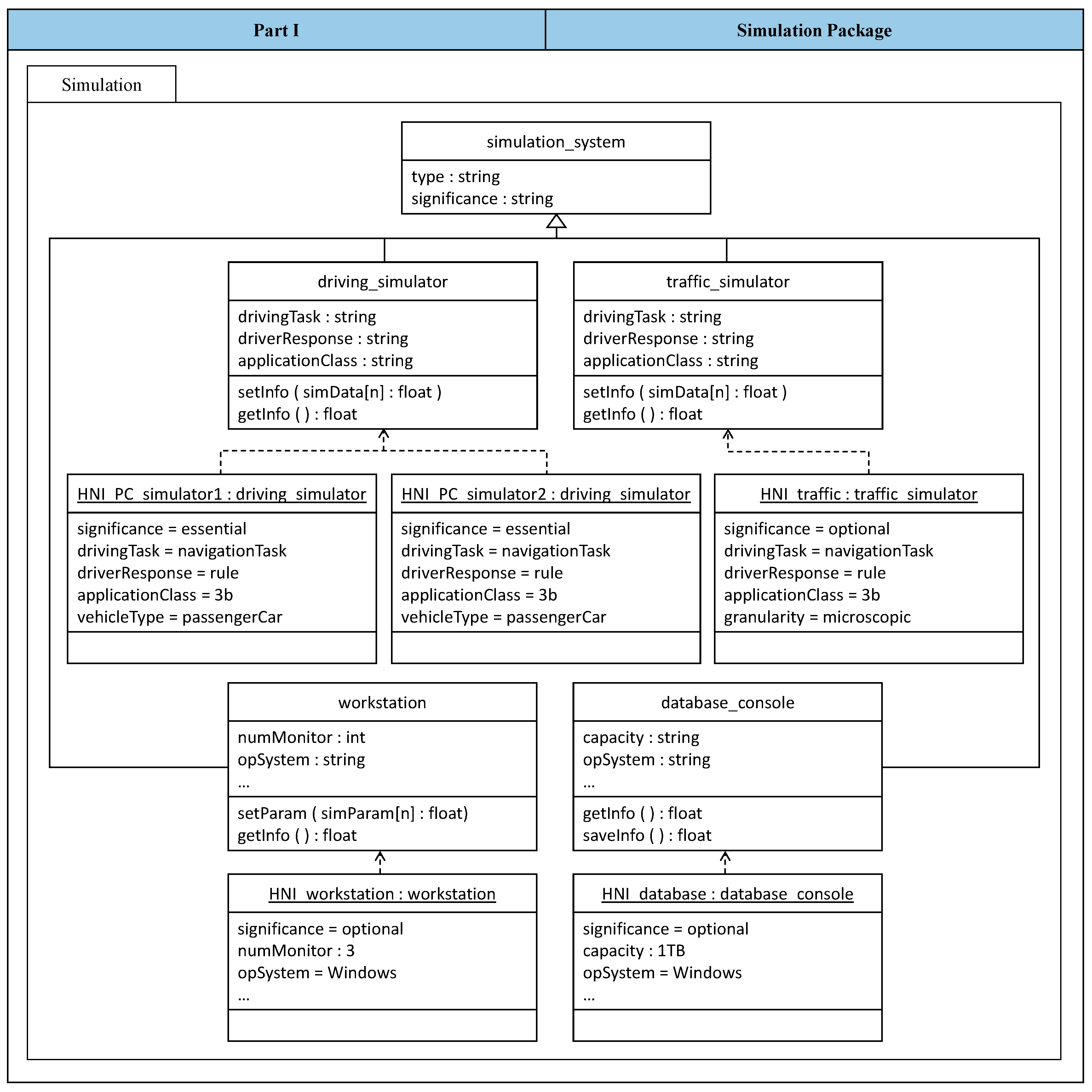
- Driving simulatorsThey are operated by human drivers to control the respective simulated vehicles. The driving simulators can be of different types, such as a passenger car simulator or a truck simulator. Moreover, driving simulators of different complexity grades can principally participate within the networked driving simulation system. By any means, the participation of at least two driving simulators is necessary not only to achieve the central purpose, but also to establish a system of networked driving simulation. If a third driving simulator is added to the system, one of the driving simulators can be eventually considered as an optional component. However, driving simulators are characterized as essential constituent systems in general.
- Traffic simulatorsThey generate traffic participants, such as programmed vehicles and pedestrians, to add more complexity to the multi-driver traffic scenario. One traffic simulator is often sufficient for the system of networked driving simulation. However, more than one traffic simulator can be integrated within the system to provide different granularity levels of traffic simulation, such as macroscopic and microscopic traffic flows [22]. The system of networked driving simulation can operate without the utilization of traffic simulators. In this case, the multi-driver traffic scenario simulation depends only on the participating interactive driving simulators. Hence, traffic simulators are characterized as optional constituent systems.
- WorkstationsA workstation is utilized to provide control and monitoring operations on the networked driving simulation system. That is, the simulation operator can make commands to stop/start the system and control particular building components. Moreover, the simulation operator can monitor various signals that give indications about the operation and performance of the system and its building components. Principally, the system of networked driving simulation can operate without the use of a workstation. Hence, the workstation is characterized as an optional building component.
- Database consolesA database console is utilized to capture and save the simulation data. Moreover, operators and developers can conduct simulation analysis or generate after-action-review reports. However, the system of networked driving simulation can operate without the use of a database console. Hence, the database console is characterized as an optional building component.
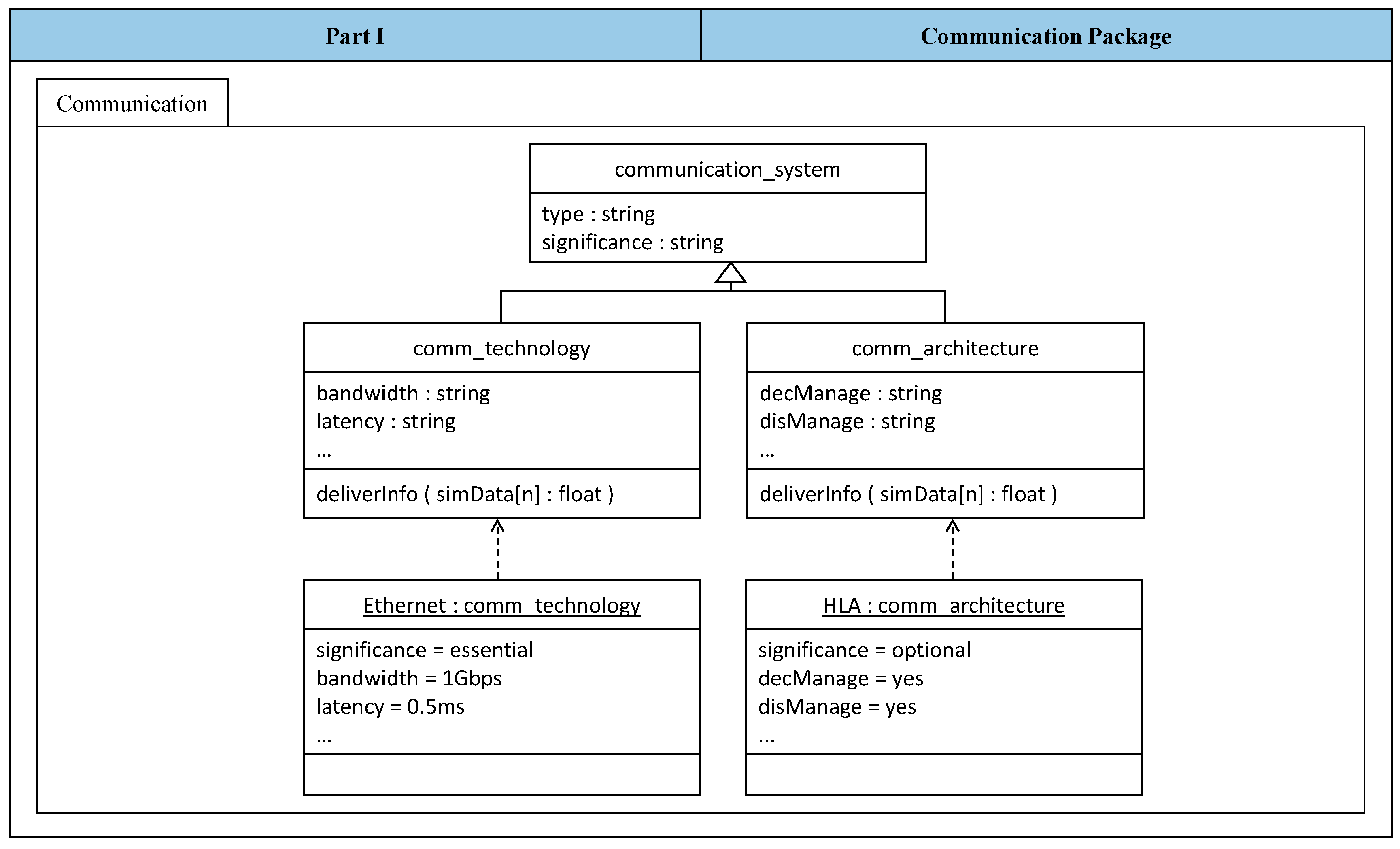
- Communication systemsIn this work, a communication system includes two categories of building components: communication technologies and communication architectures. On the one hand, the communication technologies are responsible for information exchange, such as Ethernet, CAN, and FlexRay. These communication technologies differ mainly through the provided networking characteristics. The system of networked driving simulation cannot operate without the use of a communication technology. Hence, communication technologies are characterized as essential building components. On the other hand, the communication architectures are responsible for networked simulation management, such as Distributed Interactive Simulation (DIS) and High-Level Architecture (HLA) [21,23]. These communication architectures differ mainly through the provided functions and services that can be useful for networked simulation. Unlike the communication technologies, the system of networked driving simulation can operate without the use of communication architectures. Hence, the communication architectures are characterized as optional building components. Table 9 shows the identified and described system components together with their role significance within the networked driving simulation system.
4.2.3. Classify System Components
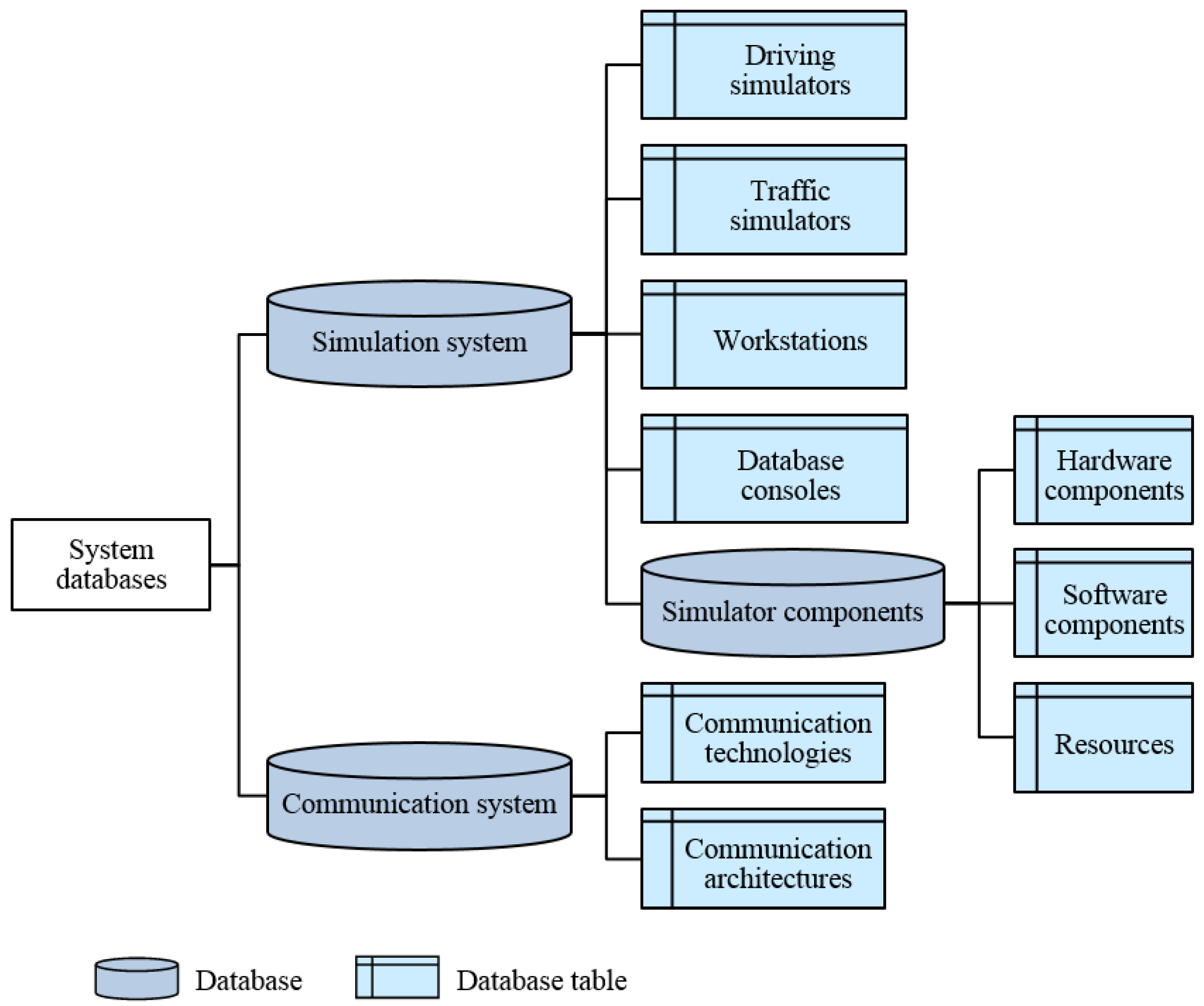
4.3. System Databases Development
4.3.1. Build System Databases for Solution Elements
4.3.2. Fill System Databases with Solution Elements
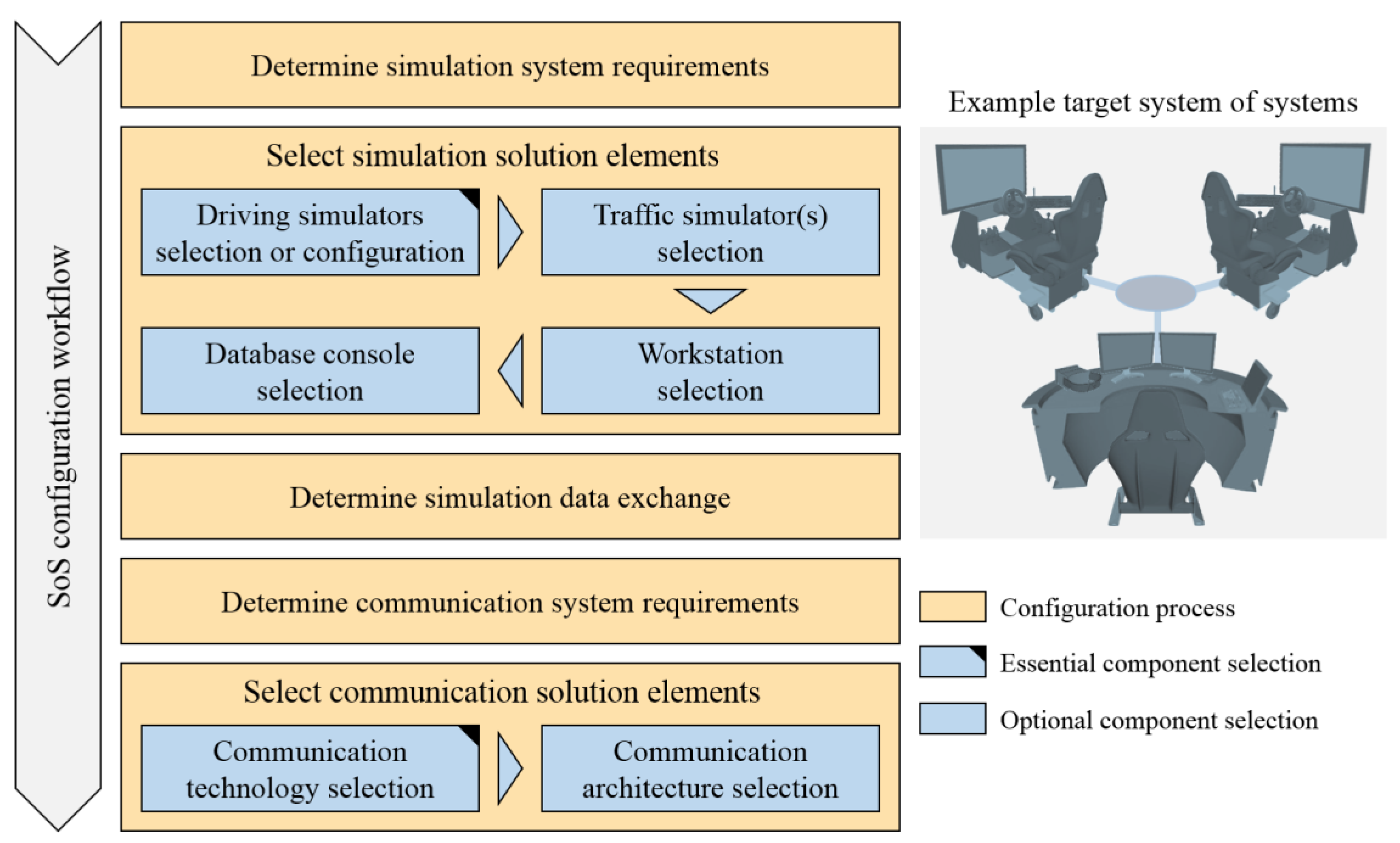
4.4. Configuration Methods Development
4.4.1. Simulation System Configuration Method
Selection Approach for Available Driving Simulators
| m | Designation of the driving simulator component |
| Significancem | Specified relative significance value of a simulator component |
| n | Designation of the feature of a driving simulator component |
| N | Maximum number of features of a driving simulator component |
| LevelReq | Requirement feature fidelity level of a simulator component |
| LevelSpec | Specification feature fidelity level of a simulator component |
Selection Approach for Further Available Simulation System Components
Selection Approach for Available Driving Simulator Components
| n | Designation of the feature of a driving simulator component |
| N | Maximum number of features of a driving simulator component |
| LevelReq | Requirement feature fidelity level of a simulator component |
| LevelSpec | Specification feature fidelity level of a simulator component |
4.4.2. Communication System Configuration Method
Determining Priority of Communication Characteristics and Functions
| n and m | Designations of the network characteristics n and m |
| M | Total number of network characteristics |
Selection Approach for Available Communication Systems
| n | Designation of the communication technology n |
| m | Designation of the communication characteristic m |
| M | Total number of communication characteristics |
4.5. System Models Development
4.5.1. Specify Configuration Sequence
4.5.2. Examine Network Behavior
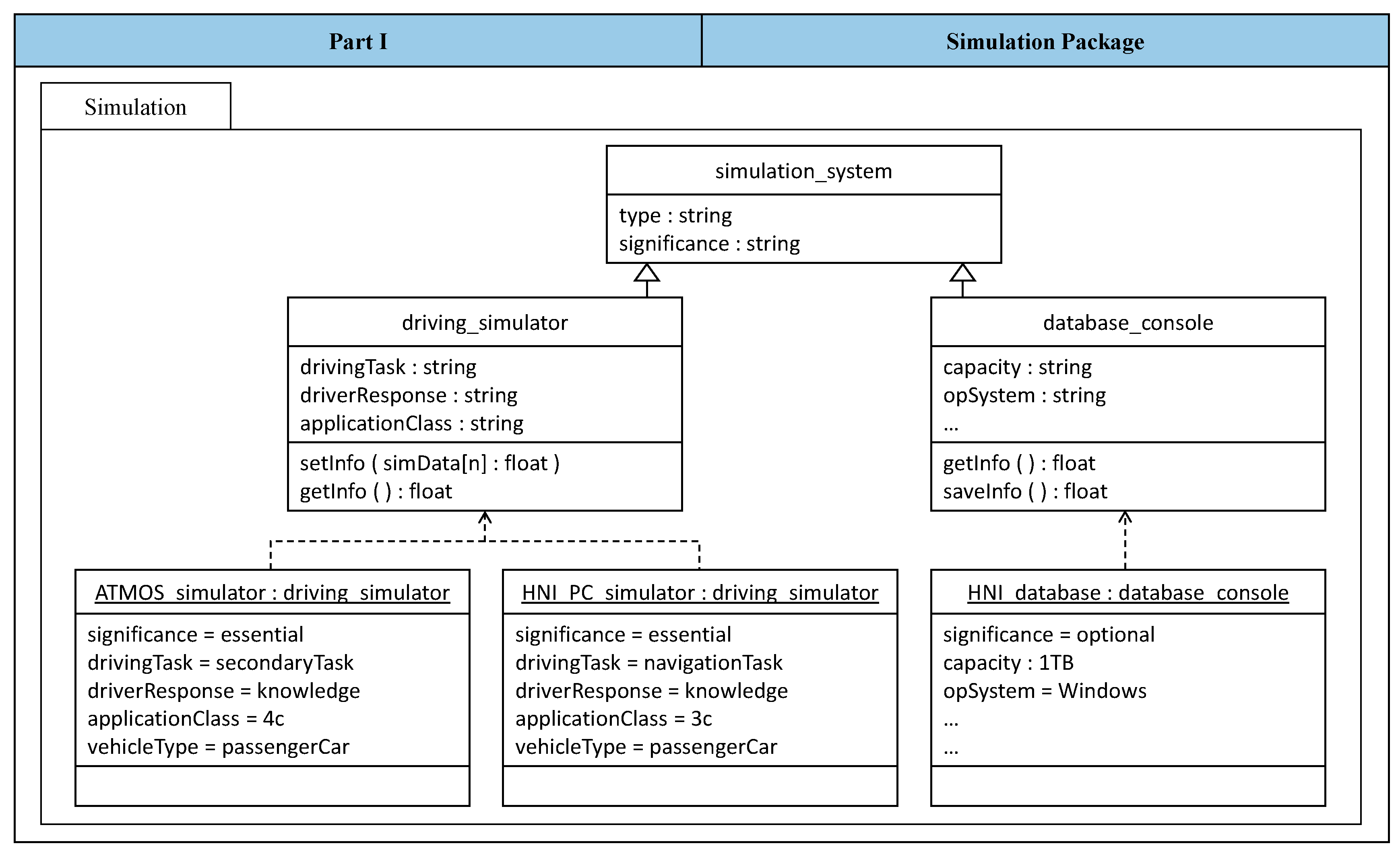
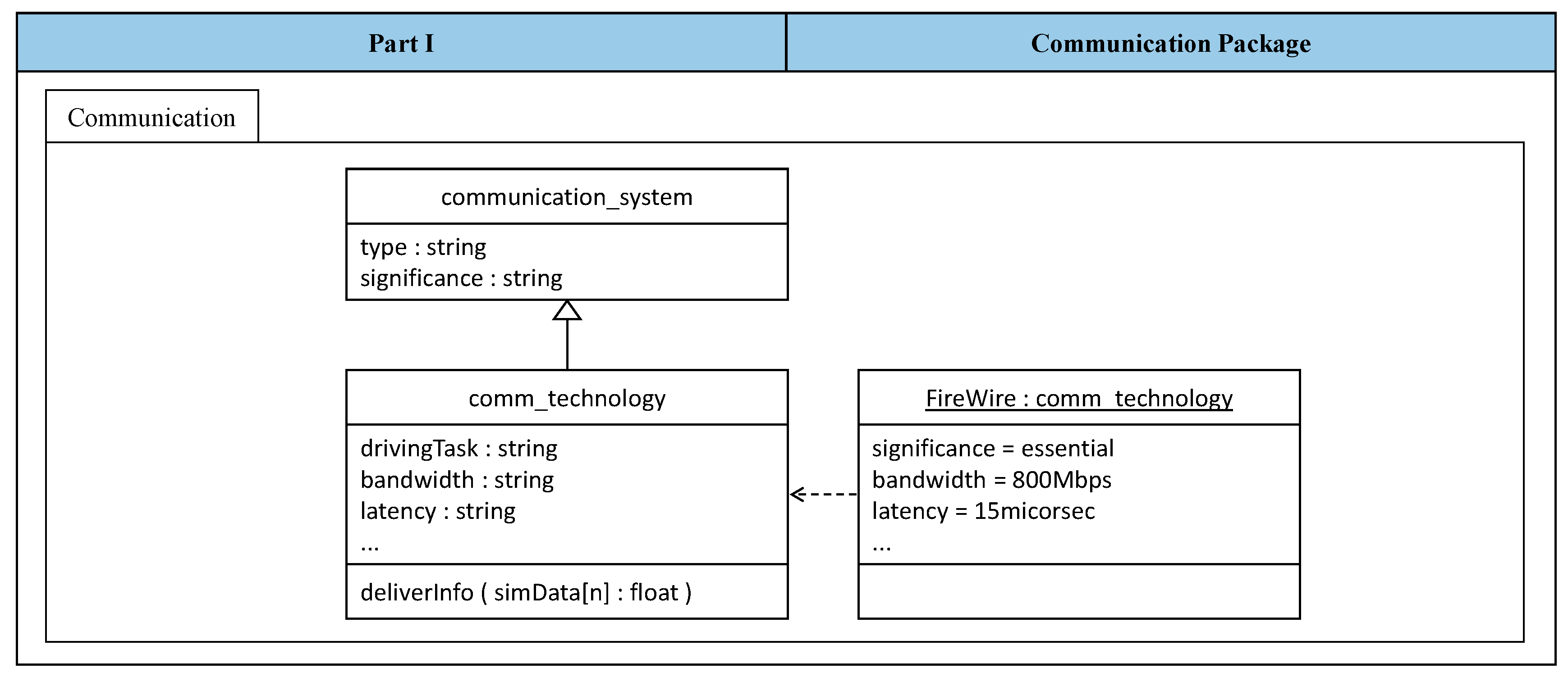
4.5.3. Generate System Models
System Model Components—Part I
System Model Components—Part II
System Model Components—Part III
5. Validation
5.1. Multi-Interactive Training with ADAS
5.1.1. Scenario Definition
5.1.2. Configuration Process
5.1.3. Generated System Model
5.2. Multi-Interactive Demonstration of an Autonomous Driving System
5.2.1. Scenario Definition
5.2.2. Configuration Process
5.2.3. Generated System Model
5.3. Multi-Interactive Analysis of Advanced Traffic Systems
5.3.1. Scenario Definition
5.3.2. Configuration Process
5.3.3. Generated System Model
6. Conclusions and Future Work
- Utilizing a well-established decision-making method for the selection of the communication components of the networked driving simulation system [29].
Acknowledgments
Author Contributions
Conflicts of Interest
References
- Wall, M.; Gausemeier, J.; Peitz, C. Technology Push-based Product Planning—Future Markets for Emerging Technologies. Int. J. Technol. Mark. 2011, 8, 61–81. [Google Scholar] [CrossRef]
- Maurer, M.; Gerdes, J.C.; Lenz, B.; Winner, H. Autonomous Driving: Technical, Legal and Social Aspects, 1st ed.; Springer: Heidelberg, Germany, 2016; ISBN 978-3-662-48845-4. [Google Scholar]
- Arioui, H.; Nehaoua, L. Driving Simulation, 1st ed.; John Wiley & Sons: Hoboken, NJ, USA, 2013; ISBN 978-1-84821-467-5. [Google Scholar]
- Winner, H.; Hakuli, S.; Lotz, F.; Singer, C. Handbook of Driver Assistance Systems: Basic Information, Components and Systems for Active Safety and Comfort, 1st ed.; Springer: Cham, Switzerland, 2015; ISBN 978-3-319-12351-6. [Google Scholar]
- Abdelgawad, K.; Gausemeier, J.; Dumitrescu, R.; Grafe, M.; Stöcklein, J.; Berssenbrügge, J. Networked Driving Simulation: Applications, State of the Art, and Design Considerations. Designs 2017, 1, 4. [Google Scholar] [CrossRef]
- Negele, H.J. Anwendungsgerechte Konzipierung von Fahrsimulatoren für die Fahrzeugentwicklung. Ph.D. Thesis, Faculty of Mechanical Engineering, University of Munich, Munich, Germany, 2007. [Google Scholar]
- Hassan, B. A Design Framework for Developing a Reconfigurable Driving Simulator. Ph.D. Thesis, Faculty of Mechanical Engineering, University of Paderborn, Paderborn, Germany, 2014. [Google Scholar]
- DiMario, M.J. System of Systems Collaborative Formation, 1st ed.; World Scientific Publishing: Singapore, 2010; pp. 29–62. ISBN 978-981-4313-88-9. [Google Scholar]
- Jamshidi, M. System of Systems Engineering: Innovations for the Twenty-first Century, 1st ed.; John Wiley & Sons: Hoboken, NJ, USA, 2008; ISBN 978-0-470-19590-1. [Google Scholar]
- Johnson, M.A. From engineering to system engineering to system of systems engineering. In Proceedings of the IEEE World Automation Congress (WAC), Hawaii, HI, USA, 28 September–2 October 2008; ISBN 978-1-889335-38-4. [Google Scholar]
- Keating, C.; Rogers, R.; Unal, R.; Dryer, D.; Sousa-Poza, A.; Safford, R.; Peterson, W.; Rabadi, G. System of systems engineering. J. Eng. Manag. 2010, 15, 36–45. [Google Scholar] [CrossRef]
- Gausemeier, J.; Czaja, A.; Wiederkehr, O.; Dumitrescu, R.; Tschirner, C.; Steffen, D. Survey: Systems Engineering in Industrial Practice. In Proceedings of the Tag des Systems Engineering, Stuttgart, Germany, 6–8 November 2013. [Google Scholar]
- Fisher, D.; Caird, J.; Rizzo, M.; Lee, J. Handbook of Driving Simulation for Engineering, Medicine, and Psychology, 1st ed.; CRC Press Taylor & Francis Group: Boca Raton, FL, USA, 2011; ISBN 978-1-4200-6100-0. [Google Scholar]
- Porter, B.E. Handbook of Traffic Psychology, 1st ed.; Academic Press, Elsevier: Waltham, MA, USA, 2011; ISBN 978-0-12-381984-0. [Google Scholar]
- Cacciabue, P.C. Guide to Applying Human Factors Methods: Human Error and Accident Management in Safety-critical Systems, 1st ed.; Springer: London, UK, 2004; ISBN 978-1-84996-898-0. [Google Scholar]
- Walker, G.H.; Stanton, N.A.; Salmon, P.M. Human Factors in Automotive Engineering and Technology, 1st ed.; Taylor and Francis Group: Boca Raton, FL, USA, 2015; ISBN 978-1-4094-4757-3. [Google Scholar]
- Pahl, G.; Beitz, W.; Feldhusen, J.; Grote, K.-H. Engineering Design: A Systematic Approach, 3rd ed.; Springer: Heidelberg, Germany, 2007; ISBN 978-1114243064. [Google Scholar]
- Hassan, B.; Gausemeier, J.; Abdelgawad, K.; Berssenbrügge, J.; Grafe, M. Systematik für Die Entwicklung von Rekonfigurierbaren Fahrsimulatoren. In Proceedings of the 12th Workshop on Augmented & Virtual Reality in Product Development, Paderborn, Germany, 23‒24 April 2015; Volume 342, pp. 213–229, ISBN 2195-5239. [Google Scholar]
- Gausemeier, J.; Frank, U.; Donoth, J.; Kahl, S. Specification technique for the description of self-optimizing mechatronic systems. J. Res. Eng. Des. 2009, 20, 201–223. [Google Scholar] [CrossRef]
- Gausemeier, J.; Rammig, F.J.; Schäfer, W. Design Methodology for Intelligent Technical Systems: Develop Intelligent Technical Systems of the Future, 1st ed.; Springer: Heidelberg, Germany, 2014; pp. 117–171. ISBN 978-3-642-45434-9. [Google Scholar]
- Wenguang, W.; Yongpinq, X.; Xin, C.; Qun, L.; Weiping, W. High level architecture evolved modular federation object model. J. Syst. Eng. Electron. 2009, 20, 625–635. [Google Scholar]
- Potuzak, T. Comparison of Road Traffic Network Division Based on Microscopic and Macroscopic Simulation. In Proceedings of the 13th International Conference on Computer Modelling and Simulation (UKSim), Cambridge, UK, 30 March–1 April 2011; ISBN 978-1-61284-705-4. [Google Scholar]
- Xu, C.; Song, J.; Chen, M.; Chen, J.; Yu, L. Research on Adaptive State Update Strategy of Distributed Interactive Simulation. In Proceedings of the 3rd IEEE International Conference on Multimedia Information Networking and Security (MINES), Shanghai, China, 4–6 November 2011; ISBN 978-1-4577-1795-6. [Google Scholar]
- Stephens, R. Beginning Database Design Solutions, 1st ed.; John Wiley & Sons: Hoboken, NJ, USA, 2008; ISBN 978-0-470-38549-4. [Google Scholar]
- Abdelgawad, K.; Hassan, B.; Berssenbrügge, J.; Stöcklein, J.; Grafe, M. A Modular Architecture of an Interactive Simulation and Training Environment for Advanced Driver Assistance Systems. Int. J. Adv. Softw. IARIA 2015, 8, 247–261. [Google Scholar]
- Mir, N.F. Computer and Communication Networks, 1st ed.; Prentice Hall: Upper Saddle River, NJ, USA, 2006; ISBN 978-0131389106. [Google Scholar]
- Doganata, Y.N.; Tantawi, A.N. Analysis of communication requirements for intelligent transportation systems: methodology and examples. In Proceedings of the 45th IEEE Vehicular Technology Conference, Chicago, IL, USA, 25–28 July 1995; ISBN 0-7803-2742-X. [Google Scholar]
- Triantaphyllou, E. Multi-criteria Decision Making Methods—A Comparative Study, 1st ed.; Springer International Publishing: Cham, Switzerland, 2000; Volume 44, pp. 5–21. ISBN 978-1-4419-4838-0. [Google Scholar]
- Brent, R.J. Applied Cost-benefit Analysis, 2nd ed.; Edward Elgar Publishing: Cheltenham, UK, 2006; ISBN 9781843768913. [Google Scholar]
- Meinel, C.; Sack, H. Internetworking: Technological Foundations and Applications, 1st ed.; Springer: Berlin, Germany, 2013; ISBN 978-3-642-35391-8. [Google Scholar]
- Wehrle, K.; Gunes, M.; Gross, J. Modeling and Tools for Network Simulation, 1st ed.; Springer: Cham, Switzerland, 2010; ISBN 978-3-642-12330-6. [Google Scholar]
- Achesona, P.; Daglia, C.; Kilicay-Ergin, N. Model Based Systems Engineering for System of Systems Using Agent-based Modeling. In Proceedings of the Conference on Systems Engineering Research (CSER’13), Atlanta, GA, USA, 19–22 March 2013. [Google Scholar] [CrossRef]
- Banos, A.; Lang, C.; Marilleau, N. Agent-Based Spatial Simulation with NetLogo, 1st ed.; ISTE Press, Elsevier: London, UK, 2015; ISBN 9781785480553. [Google Scholar]
- Bersini, H. UML for ABM. J. Artif. Soc. Soc. Simul. 2012, 15. [Google Scholar] [CrossRef]
- Rumpe, B. Modeling with UML: Language, Concepts, Methods, 1st ed.; Springer: Cham, Switzerland, 2016; ISBN 978-3-319-33932-0. [Google Scholar]
- Sarbazi-Azad, H.; Zomaya, A.Y. Data Distribution Management, 1st ed.; Wiley-IEEE Press: Hoboken, NJ, USA, 2014; ISBN 9781118640708. [Google Scholar]
- Rambhia, A.M. XML Distributed Systems Design, 1st ed.; Sams Publishing: Indian-apolis, IN, USA, 2002; ISBN 978-0672323287. [Google Scholar]
- Cutler, M.; Walsh, T.J.; How, J.P. Reinforcement learning with multi-fidelity simulators. In Proceedings of the IEEE International Conference on Robotics and Automation (ICRA), Hong Kong, China, 31 May–7 June 2014; ISBN 978-1-4799-3686-1. [Google Scholar]
- Planing, P. Innovation Acceptance: The Case of Advanced Driver-Assistance Systems. Ph.D. Thesis, Faculty of Mechanical Engineering, Leeds Metropolitan University, Leeds, UK, 2007. [Google Scholar]
- Voss, W. A Comprehensible Guide to Controller Area Network, 2nd ed.; Copperhill Media Corporation: Greenfield, MA, USA, 2015; ISBN 978-0976511601. [Google Scholar]
- Anderson, D. FireWire System Architecture: IEEE 1394A, 2nd ed.; Addison-Wesley Professional: Boston, MA, USA, 1998; ISBN 978-0201485356. [Google Scholar]
- Wuthishuwong, C.; Traechtler, A.; Bruns, T. Safe Trajectory Planning for Autonomous Intersection Management by Using Vehicle to Infrastructure Communication. J. Wirel. Commun. Netw. 2015, 33. [Google Scholar] [CrossRef]
- Barcelo, J. Fundamentals of Traffic Simulation, 1st ed.; Springer Science & Business Media: New York, NY, USA, 2010; ISBN 978-1-4419-6141-9. [Google Scholar]
- Stevens, A.; Brusque, C.; Krems, J. Driver Adaptation to Information and Assistance Systems, 1st ed.; Institution of Engineering and Technology: London, UK, 2013; ISBN 978-1-84919-639-0. [Google Scholar]
- Abdelgawad, K.; Henning, S.; Biemelt, P.; Gausemeier, S.; Trächtler, A. Advanced traffic simulation framework for networked driving simulators. In Proceedings of the 8th IFAC Conference on Advances in Automotive Control (ACC), Norrköping, Sweden, 20–23 June 2016; Volume 49, pp. 101–108. [Google Scholar]
- Abdelgawad, K.; Gausemeier, J.; Grafe, M.; Berssenbrügge, J. Interest Manager for Networked Driving Simulation Based on High-Level Architecture. Designs 2017, 1, 3. [Google Scholar] [CrossRef]


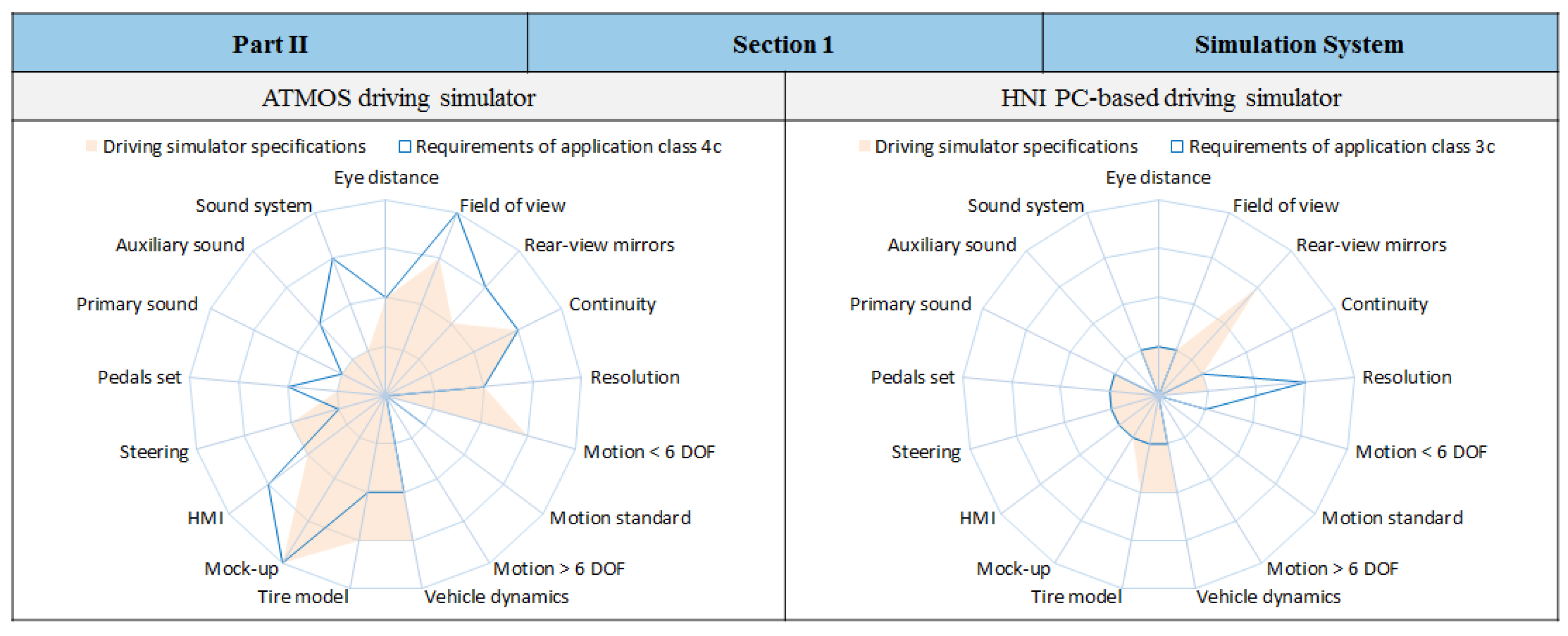
| Feature | Key | Fidelity Levels |
|---|---|---|
| Mock-up | S1 | Driving seat and HMI without chassis |
| S2 | Partial vehicle (quarter or half vehicle) | |
| S3 | Complete vehicle—no modifications apparent | |
| S4 | Series production vehicle—no modifications apparent | |
| HMI | T1 | Basic and simple HMI |
| T2 | Complete and realistic HMI | |
| T3 | Complete HMI with reconfigurable display | |
| Steering | U1 | Steering moment proportional to steering angle |
| U2 | Electrical steering moment, damping, and friction | |
| U3 | Electrical steering moment with high frequency | |
| Pedals Set | V1 | Passive force feedback |
| V2 | Adaptive force feedback—modifiable characteristic curve | |
| V3 | Active force feedback—tangible effects of control systems |
| Scene Simulation | ||
| Viewing distance (A1) | Field of view (B2) | Stereo vision (None) |
| Head tracking (None) | Rear-view mirrors (E2) | Field continuity (F3) |
| Resolution (G2) | Frame rate (H1) | Projector type (J2) |
| Motion Simulation | ||
| Motion platform < 6 DOF (K1) | Standard platform = 6 DOF (None) | Standard platform > 6 DOF (M1/M2/M3) |
| Vehicle dynamics (N3) | Tire (O4) | |
| Driver’s Platform | ||
| Mock-up (S3) | HMI (T2) | Steering (U3) |
| Pedals set (V2) | ||
| Acoustic Simulation | ||
| Primary sound P1 (P2) | Auxiliary sound (Q1) | Sound system (R1, R3) |
| Environment Database | ||
| Database type (W1) | District type (Y1) | |
| Traffic Objects Simulation | ||
| General traffic vehicles (Z1) | Special objects (None) | |
| Driving Simulator Components | Solution Elements | ||
|---|---|---|---|
| 1 | 2 | 3 | |
| Scene Simulation System |  |  |  |
| Motion Simulation System |  |  |  |
| Driver’s Platform |  |  |  |
| Acoustic Simulation System |  |  |  |
| Environment Database |  |  |  |
| Traffic Objects Simulation |  |  |  |
| Dependency Scheme | Hardware | Software | ||||||||
|---|---|---|---|---|---|---|---|---|---|---|
| 0 = Independent Components 1 = Dependent Components | Visualization System | Motion Platform | Human-Machine Interface | Acoustic System | Visualization Software | Platform Controller | Vehicle Dynamics | HMI Software | Acoustic Software | |
| Hardware | Visualization system | x | ||||||||
| Motion platform | 1 | x | ||||||||
| Human-machine interface | 0 | 1 | x | |||||||
| Acoustic system | 0 | 0 | 0 | x | ||||||
| Software | Visualization software | 1 | 0 | 0 | 0 | x | ||||
| Platform controller | 0 | 1 | 0 | 0 | 0 | x | ||||
| Vehicle dynamics | 0 | 0 | 0 | 0 | 0 | 0 | x | |||
| HMI software | 0 | 0 | 1 | 0 | 0 | 0 | 0 | x | ||
| Acoustic software | 0 | 0 | 0 | 1 | 0 | 0 | 0 | 0 | x | |
| Consistency Scheme | Hardware | |||||||||
|---|---|---|---|---|---|---|---|---|---|---|
| 0 = Inconsistent Solution Elements 1 = Independent Solution Elements 2 = Consistent Solution Elements | Visualization System | Motion Platform | Human Machine Interface | Acoustic System | ||||||
| A | B | A | B | A | B | A | B | |||
| Hardware | Visualization system | A | x | x | ||||||
| B | x | x | ||||||||
| Motion platform | A | 2 | 0 | x | x | |||||
| B | 0 | 2 | x | x | ||||||
| Human machine interface | A | 1 | 1 | 2 | 0 | x | x | |||
| B | 1 | 1 | 0 | 2 | x | x | ||||
| Acoustic system | A | 1 | 1 | 1 | 1 | 1 | 1 | x | x | |
| B | 1 | 1 | 1 | 1 | 1 | 1 | x | x | ||
| Application Scenario 1 | Multi-Driver Training in Driving Schools | Status 1 September 2017 | Page 1 | ||
|---|---|---|---|---|---|
| Description: An instructor at a driving school handles two trainees simultaneously in realistic and multi-interactive traffic scenarios. The trainees share a virtual traffic environment. They have to react to each other and adapt their driving behavior. | |||||
| Simulation System | |||||
| Simulation Entities | Supplementary Components | ||||
| Driving simulator 1 | Driving simulator 2 | Workstation | |||
| Trainee 1 uses this driving simulator to experience different traffic situations in a safe virtual environment. | Trainee 2 uses this driving simulator to experience different traffic situations in a safe virtual environment. | Purpose of use: the driving instructor uses the work station to control and monitor the training session. | |||
| Communication System | |||||
| Communication Technology | Communication Architecture | ||||
| It is a feasible communication technology that ensures a data exchange with little delay and loss rates. | To maintain system feasibility for driving schools, no communication architecture is utilized in this application scenario. | ||||
| Sketch | |||||
 | |||||
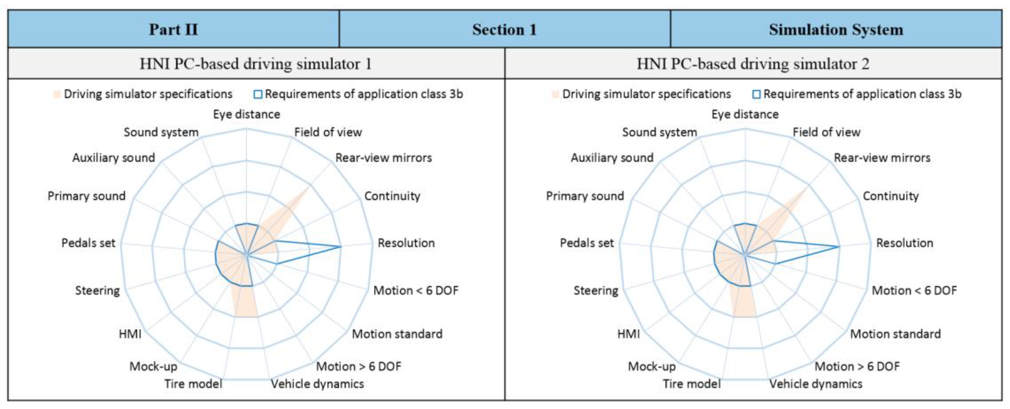
| ID | No. | Requirements of Networked Driving Simulation | D/W |
|---|---|---|---|
| 1 | Requirement of Driving Simulator 1 | ||
| 1 | Scene simulation system | ||
| 1.1 | It shall cover a 120° horizontal field of view | D | |
| … | … | ||
| 2 | Motion simulation system | ||
| 2.1 | It shall provide three degrees of freedom | W | |
| … | … | ||
| 2 | Requirement of Driving Simulator 2 | ||
| 1 | Scene simulation system | ||
| 1.1 | It shall cover a 240° horizontal field of view | W | |
| … | … | ||
| 2 | Motion simulation system | ||
| 2.1 | It shall provide five degrees of freedom | D | |
| … | … | ||
| Distinction | System Components of Networked Driving Simulation | ||||
|---|---|---|---|---|---|
| Driving Simulators | Traffic Simulators | Workstations | Database Consoles | Communication Systems | |
| Constituent System | x | x | |||
| Building Component | x | x | x | ||
| Role Significance | Components of Networked Driving Simulation Systems | |||||
|---|---|---|---|---|---|---|
| Constituent Systems | Building Components | |||||
| Driving Simulators | Traffic Simulators | Workstations | Database Consoles | Comm. Technologies | Comm. Architectures | |
| Essential Component | x | x | ||||
| Optional Component | x | x | x | x | ||
| ID | Name | Visualization System | Motion System | Acoustic System | Driver Platform | |||||||||||||
|---|---|---|---|---|---|---|---|---|---|---|---|---|---|---|---|---|---|---|
| Eye Distance (A) | Field of View (B) | Rear-View Mirrors (E) | Continuity (F) | Resolution (G) | Motion Standard (L) | Motion < 6 DOF (K) | Motion > 6 DOF (M) | Vehicle Dynamics (N) | Tire Model (O) | Primary Sound (P) | Auxiliary Sound (Q) | Sound System (R) | Mock-Up (S) | HMI (T) | Steering (U) | Pedals Set (V) | ||
| 1 | ATMOS simulator | 2 | 3 | 2 | 3 | 2 | ‒ | 3 | ‒ | 3 | 3 | 1 | 1 | 1 | 4 | 2 | 2 | 1 |
| 2 | Airmotion _ride | 2 | 1 | 3 | 1 | 2 | 1 | ‒ | ‒ | 2 | 2 | 1 | 1 | 1 | 1 | 1 | 1 | 1 |
| 3 | HNI PC simulator | 1 | 1 | 3 | 1 | 1 | ‒ | ‒ | ‒ | 2 | 2 | 1 | ‒ | 1 | 1 | 1 | 1 | 1 |
| System Components | Solution Elements | ||
|---|---|---|---|
| 1 | 2 | 3 | |
| Driving Simulators |  |  |  |
| Traffic Simulators |  |  |  |
| Workstations |  |  |  |
| Database Consoles |  |  |  |
| Communication Technologies |  |  |  |
| Communication Architectures |  |  |  |
| Example Driving Simulators | Specified Driving Simulator Application Classes | |||||||
|---|---|---|---|---|---|---|---|---|
| 1a | 2b | 3b | 3c | 4b | 4c | 5b | 5c | |
| ATMOS driving simulator | 2.04 | 2.15 | 3.22 | 3.22 | 2.00 | 1.81 | 2.00 | 2.00 |
| Airmotion_ride driving simulator | 3.26 | 2.23 | 1.48 | 1.48 | 1.38 | 2.38 | 1.80 | 1.80 |
| HNI PC-based driving simulator | 3.15 | 2.30 | 1.30 | 1.30 | 1.96 | 2.96 | 1.78 | 1.78 |
| Priority Scheme 1 = Equally Important 5 = More Important 10 = Much More Important 0.2 = Less Important 0.1 = Much Less Important | Network Characteristics | Sum of Weights | Priority Weight (%) | ||||
|---|---|---|---|---|---|---|---|
| Bandwidth | Packet Loss Rate | Determinism | Latency | Segment Length | |||
| Bandwidth | x | 5 | 0.2 | 1 | 10 | 16.2 | 29.35 |
| Packet loss rate | 0.2 | x | 0.2 | 1 | 5 | 6.4 | 11.59 |
| Determinism | 5 | 5 | x | 5 | 10 | 25 | 45.29 |
| Latency | 1 | 1 | 0.2 | x | 5 | 7.2 | 13.04 |
| Segment length | 0.1 | 0.2 | 0.1 | 0.2 | x | 0.4 | 0.730 |
| Network Characteristics | Priority Weight (%) | Communication Technologies | |||||
|---|---|---|---|---|---|---|---|
| Ethernet 10 Mbps | CAN Bus | InfiniBand | |||||
| Fulfillment (%) | Partial Assessment (%) | Fulfillment (%) | Partial Assessment (%) | Fulfillment (%) | Partial Assessment (%) | ||
| Bandwidth | 29.35 | 80 | 23.5 | 20 | 5.87 | 100 | 29.4 |
| Packet loss rate | 11.59 | 10 | 1.16 | 100 | 11.6 | 100 | 11.6 |
| Determinism | 45.29 | 00 | 0.00 | 100 | 45.3 | 00 | 0.00 |
| Latency | 13.04 | 00 | 0.00 | 100 | 13.0 | 00 | 0.00 |
| Segment length | 0.730 | 100 | 0.73 | 50 | 0.37 | 30 | 0.22 |
| Final assessment (%) | 25.39 | 76.14 | 41.22 | ||||
© 2017 by the authors. Licensee MDPI, Basel, Switzerland. This article is an open access article distributed under the terms and conditions of the Creative Commons Attribution (CC BY) license (http://creativecommons.org/licenses/by/4.0/).
Share and Cite
Abdelgawad, K.; Gausemeier, J.; Trächtler, A.; Gausemeier, S.; Dumitrescu, R.; Berssenbrügge, J.; Stöcklein, J.; Grafe, M. An Application-Oriented Design Method for Networked Driving Simulation. Designs 2017, 1, 6. https://doi.org/10.3390/designs1010006
Abdelgawad K, Gausemeier J, Trächtler A, Gausemeier S, Dumitrescu R, Berssenbrügge J, Stöcklein J, Grafe M. An Application-Oriented Design Method for Networked Driving Simulation. Designs. 2017; 1(1):6. https://doi.org/10.3390/designs1010006
Chicago/Turabian StyleAbdelgawad, Kareem, Jürgen Gausemeier, Ansgar Trächtler, Sandra Gausemeier, Roman Dumitrescu, Jan Berssenbrügge, Jörg Stöcklein, and Michael Grafe. 2017. "An Application-Oriented Design Method for Networked Driving Simulation" Designs 1, no. 1: 6. https://doi.org/10.3390/designs1010006