A Structurally Enhanced, Ergonomically and Human–Computer Interaction Improved Intelligent Seat’s System †

1
Department of Industrial Design, Rhode Island School of Design, Providence, RI 02908, USA
2
Department of Civil Engineering, Zhejiang University, Hangzhou 310058, China
3
Department of Industrial Design, Zhejiang University, Hangzhou 310058, China
4
Department of Engineering Product Development, Singapore University of Technology and Design, Singapore 487372, Singapore
5
Department of Industrial Design, University of Science & Technology, Beijing 100083, China
6
Department of Mathematics, Pace University, New York, NY 10038, USA
*
Author to whom correspondence should be addressed.
†
This paper is an extended version of paper published in the Second International Conference on Advanced Technology and Business, Fort Collins, CO, USA, 27–28 December 2015.
Designs 2017, 1(2), 11; https://doi.org/10.3390/designs1020011
Submission received: 28 September 2017
/
Revised: 9 November 2017
/
Accepted: 18 November 2017
/
Published: 29 November 2017
(This article belongs to the Special Issue Road Vehicle Safety: Design and Assessment)
Abstract
:Featured Application
The potential application of this seating system lies in the field of manufacturing process for airplane seating system. This paper provides a prototype for the mold processing, manufacturing flow and logistics for industrial engineering. The potential application will improve the early stage prototype iteration, and speed up the product design and manufacturing process. In addition, the concept-driven design process closely integrates human needs, and it can optimize the cost and quality in the early stage design.
Abstract
Modern technology advances airplane seat design with better ergonomics and new HCI (human-computer interaction). However, airline companies are not motivated to replace the seat system due to the cost consideration. Hence, a series of re-optimized design in ergonomics and HCI should be carried out by designers. This paper describes a novel intelligent seat’s system, which is designed to be used for the airplanes or similar conditions. This system consists of redesigned ergonomics and HCI compared with original seat’s systems. The mainly redesigned parts are the aesthetics and visual modeling for people to receive visual information, the ergonomics part for people to receive tactile information, new users’ action innovation for people to receive and output information, the redesign of the structure of the system with low weight and cost, and the functional system environment for people to receive information from humans through movement in multiple environments. Structural analysis supports the redesign. The purpose of the redesign is to improve the HCI system with new tech and interaction.
1. Introduction
The re-design of airline seats’ systems for improved ergonomics and human–computer interaction will be described in this article. As the seat system evolves, quite a lot of new HCI design of the new tech seat system is required to overcome the challenges that emerge. Various companies all over the globe have begun designing new HCI for the new seat system [1]. Microsoft, Google and other US companies did a lot of work on the tech based HCI. Japanese companies concentrated on the design with tech and cultural elements. This paper describes a novel intelligent seat’s system based on former design [2].
Modern technology has provided considerable progress in the area of aircraft seats and seating systems. However, airline companies haven’t improved seat systems for 7–10 years because the US Federal Aviation Administration (FAA) of the head injury criterion (HIC) is quite costly, and the complexity requires a long time to conduct the test. It is required that when aircraft lands in an emergency or, in the case when a plane can not take off, the redesigned seat system should not have a significant impact on the passenger’s head. The rule is to make sure that passengers can at least stay alive, and better stay conscious, so that passengers can run away timely in case of any accident. The human face is fragile, and, when the face hits the side screen, the chances for a passenger's survival and ability to flee away might be reduced [3].
Some people have complaints because of the uncomfortable nature of the seats of some current airline companies. For a long time, some people have believed that the HCI and ergonomics of the seat system is old and needs updating. Hence, a series of re-optimized designs in ergonomics and HCI is required from the designers. Based on research of the new tech and interactive study, this article illustrates a redesigned system. The new design proposed here is according to the User’s Centered Design. The new design of seat systems for aircraft use, or for any other tech seat systems, have the following requirements: comfort, passenger’s space optimization, and IFE (In Flight Entertainment) Functionality. The following research areas are highlighted in this paper: Aesthetics, Ergonomics, Innovation, Functionality, Weight, and Interaction.
The theoretical analysis for human machine engineering and interaction about the seating system involves the following: users’ feeling, perception, learning, error and correction, memorization, and generation of emotions. In the interaction process between the user and the seating system, to optimize the interaction experience, the entire design method will be described, and a test for the design content will be demonstrated.
The theoretical analysis for the ergonomics in seating systems focuses on the following three parts: the relationship between humans and seating systems; the harmony for humans, seating and the environment; and the impressions and feelings from the unique design of the seating system on users. In addition, structural and design methodology analysis will be conducted for the seating ergonomics, and the test of the design content will be demonstrated.
For the concept-driven design, the purpose of all the methodologies, data and experimental demonstration in this paper are to control the early stage concept design through the initial concept demonstrations. The concept-driven design, from a macro perspective, can promote the detailed industrial design, launch the entire design from human’s essential needs, and derive the origins of the concept design for the seating system.
The design concept in this paper is as follows:
- -
- Aesthetic: formal and visual transmission of information from humans
- -
- Ergonomics: sensorial transmission of information from humans
- -
- Interaction: transmission and reception of information from humans through movement
- -
- Structure, weight, and cost: reception of information from humans through movement in a single environment
From all of these aspects, the users’ needs can be more accurately understood, and a reasonable design scheme can be developed for the final product. Design details and demonstrations will be discussed.
Design Goal
Problem: The HCI of a current intelligence tech seat system needs improvement. The main users of this problem were middle-aged mid-range business aircraft passengers or ordinary automobile drivers.
Problems scenarios: Passengers in the automobiles or airplanes with various interactive actions emerged as using high tech instruments. Design tasks: the aesthetics and visual modeling for users to receive visual input, the ergonomics part for users to get tactile information, a new user’s action innovation for users to communicate information, the redesign of the structure of the seat system with lower weight and cost, the functional system environment for users to get information from users through movements in various environments.
2. Design Concept
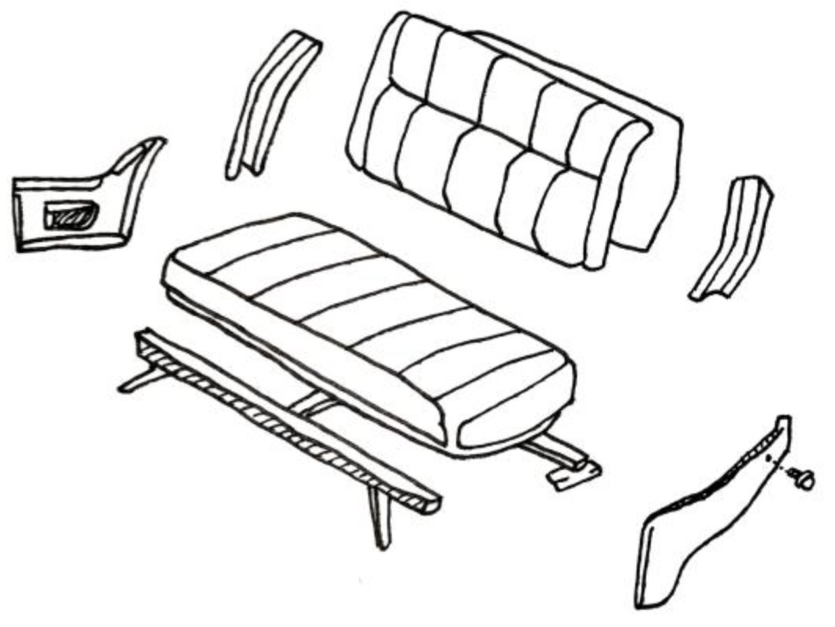
The mind mapping below illustrates the design process for this design goal with complexity. Some design sketches showing the design concepts also help to make the design more useful and more interesting.
After mind mapping, the following points are concluded and summarized here: redesigned ergonomics and HCI in original seat’s systems, the aesthetics and visual modeling for people to receive visual information, the ergonomics part for person to receive tactile information [4], a new user’s action innovation for people to receive and output information, the redesign of the structure of the system with low weight and cost, and the functional system environment for people to receive information from humans through movements in multiple environments. The basic design concept and ideas can be basically seen from Figure 1.
3. Aesthetic—Formal and Visual Transmission of Information from Humans
To improve the seat system, the first thing to do after the concepts is to change the form and visual shape, in order to let people have a better impression of the seat system.
3.1. Design Composition and Curve Coordination
The famous artist Kandinsky’s theory [5] laid the foundation for the aesthetic design of the seat system.
When people see the shape of the products, it is better for them to be comfortable and feel calm. To put the point and line’s constitution in a great reconstruction of the product will achieve the design goal. The idea of this theory can be seen from Figure 2.
Repeated equal-spaced straight lines are the easiest design scene, so as the basic rhythm, minute interval times, or repeated at intervals. As shown in Figure 3.
First, the first iteration aimed at increasing the amount of repetition, as pictures of the scene. If you rely on a lot of violin music, play to enhance the sound of the violin.
The second iteration—except for the amount of enhancement, there is sense of quality in music generally similar to repeating the same section of music after a long pause [5].
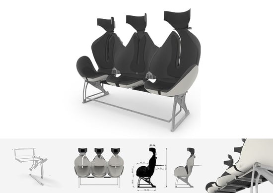
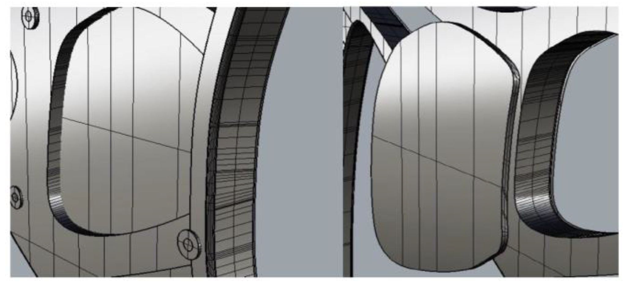
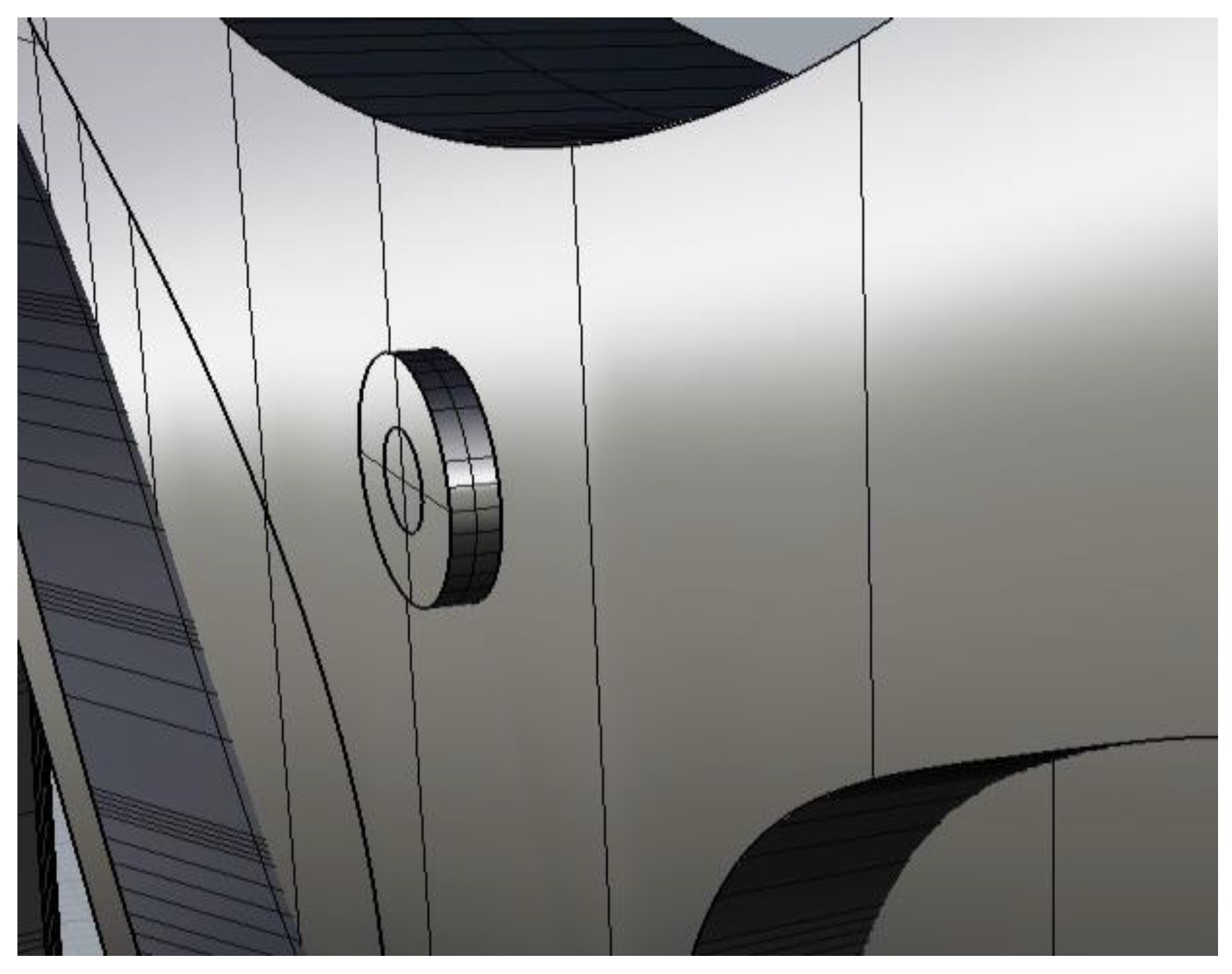
In this article, the design is based on Kandinsky’s theory, and the goal is to make the shape of the seat system shown in Figure 4 in a curved coordination and a great design composition.
3.2. Design Semantics
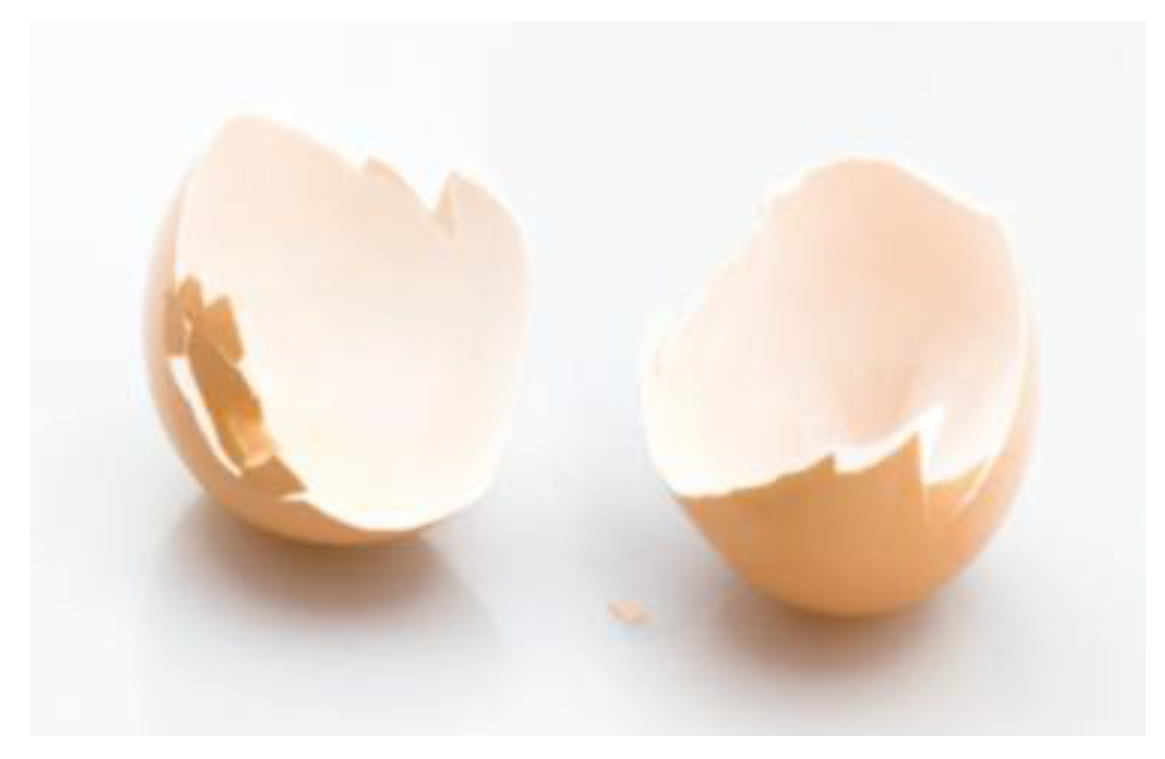
The way that the seat system is reconstructed is illustrated here. The new structure is inspired by a common object in daily lives: the eggshell. For the embryo, the eggshell is an important structure [6]. Firstly, the eggshell forms a chamber with safety for the new developing embryo. Secondly, a structural protection and controlled gas medium are also provided by the shell. As the Figure 5 shows.
The main idea for the design is to design a new structure just like the embryo, with a cozy environment and secured environment, offering the passenger the most security and great feeling for the entire journey. Then, the re-designed model, will include more modern style elements, and more interaction with the passenger. The model is shown in Figure 6.
Color: Contrasting colors form the basis of modern design. Meanwhile, small details such as the handles have a combination of black and white to add to the element of mystery without being so boring. In artistic terms, this is known as the penetration of point, line and plane.
Shape: Eggshells are one of the most natural, beautiful and secure structures. We use ergonomics factors to define the main space of the seat as well as using passengers’ behavior as one of our factors in making decisions.
The seat handles are different from the traditional ones, for not only do they cater to the shape and moving actions of our arms, but they are also able to change in shape. The cushion, redesigned to stimulate a circle form known as “Yin-Yang”, provides an element of traditionalism.
The back rest is also a combination of aesthetic and ergonomics by providing the best of both worlds in terms of passengers’ comfort and space.
Hollow Spaces: Through research, we optimize the area of the backseat to cater to the main pressure points. Thus, we decided to make the back rest and seat bottom hollow [6]. This does not reduce the strength and stiffness of the material but reduces the material costs. Furthermore, we design the cut in such a way that not only does it look aesthetically stunning, but it is also able to outline the shape of the body and allow the passengers to feel as one with the spaces.
Crafts: Designers are born from craftsman. Thus, we incorporate the act of crafting when designing. We have read through many design references about molding and material books for crafting, as we want to search for the easiest and most cost-efficient way for producing it.
The result is that the most efficient way is to piece up various parts together like a Lego set. This repetitive process makes it fast and easy for factories to produce it and easier for aircraft servants to clean it. Furthermore, the black surface of the cushion makes it easier to keep it from getting dirty.
All in all, the shape of an egg provides an integral feeling: beautiful in and out, and full of inspiration of modern internationalism design.
4. Ergonomics—Sensorial Transmission of Information from Humans
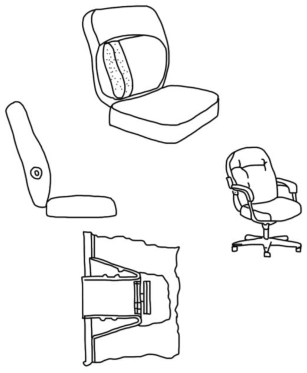
After the aesthetic part, careful design is needed for the sensorial transmission of the information from humans. By analyzing the body posture and pressure points on human bodies subjected to prolonged seating, the design is considered in terms of ergonomics. The positions of the sensors are illustrated in Figure 7.
For improvement of the comfort, the seating system automatically adjusts the position to better fit the passenger’s situation. Some sensors will be installed inside the back cushion to monitor the physical signal from the passengers. Some body movements or non-movements may indicate that the passenger falls asleep, which is when the seat needs to be adjusted. Furthermore, some cardiorespiratory signals will also be monitored, such as heart rates and respiration, to offer more options. Specifically, in order to extract the proposed cardiorespiratory information from the original signals, some adaptive data processing algorithms need to be developed and utilized, both for PVDF (polyvinylidene fluoride) film sensors and conductive fabric sensors. The data from the research can be see from Table 1 and Table 2. Simple and powerful data processing algorithms are therefore described and testified as follows, according to cardiorespiratory information extracted from PVDF sensor output and conductive fabric sensor output.
From the deduction from the data above, it can be optimized for the ideal seat height, area for construction and the support areas. All of these need to be focused on, as well as some other information that should not be neglected.
Firstly, the passenger’s back is supposed to be in the most comfortable position, when it is not restricted to a limited space. This is when the lumbar vertebra will be in a lordosis position (Lordosis is the inward curvature of a portion of the lumbar and cervical vertebral column.). At the same time, the back and bottom of the seat should be strong enough to support the weight of the passenger.
Generally, the point force point of an adult’s lumbar vertebra is about 23 to 26 cm higher than the seat. For this reason, according to these measurements, the product will be designed so that the support will be higher than the force point, so that it is strong enough to support the back when the passenger lays back.
The other two important points should also be positioned on the shoulder rest and the lumbar rest. However, most of the time, lumbar will be the main part to exert the force. The back rest can be ranged from 48 to 63 cm in width, and 35 to 48 cm in height.
Secondly, only a small area of the bottom will be in contact with the seat when the passenger is seated. Detailed calculations suggested that nearly 75% of the passenger’s body weight is supported by around 25 cm2 of this contact area with the cushion. Not only will this result in a big stress exerted on our back, causing soreness in the backbone area, but it is also the reason for pain and aches after prolonged sitting. Adding a cushion on the back can greatly lower the pressure exerted on the back because the contact area is increased. In this case, the cushion acts as a support for the proper seating position [9].
Lastly, from the observation and surveying, it is obvious that passengers will not remain rigid in the seats with the same position for a prolonged period. Thus, to better utilize the material, it is logical and cost efficient to reduce the amount of material used in the seat back components, while, at the same time, not failing to maintain the comfort of the passenger throughout the entire trip.
4.1. Size of Seats
Based on the research, the dimensions of seating position of both male and females were collected to maximize the comfort the majority of our passengers, the detailed data is listed in Table 3.
This data shown in Table 4 provides the basis to the modelling work, as the requirement is to meet the population distribution, taking 50% of the passengers as men. The following takes the 50th percentile of each piece of data.
Conclusion—cushion area: the ischium endures the largest pressure, which decreases gradually as it spreads out; the smallest pressure is supplied by the thighs.
The back rest can range from 48 to 63 cm in width and 35 to 48 cm in height: the shoulder blade and lumbar vertebra are two main supporting points, and pressure gradually reduces outwards along the two points.
The right and the left back seat experience the same pressure.
The seat should suit the shapes of back, legs and the bottom of thighs.
Two supporting points: one is between the fifth and sixth thoracic vertebras; the other is on the waist.
5. Interaction—Transmission and Reception of Information from Humans through Movements
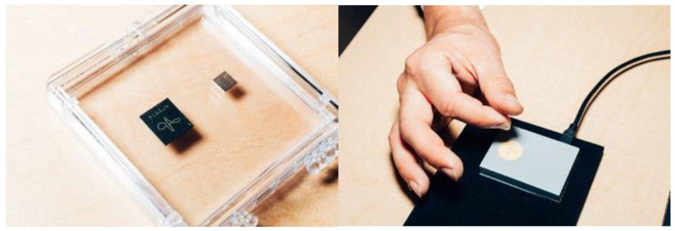
To equip the system with a smarter HCI and make it more useful, the redesigned system needs to be good in terms of both ergonomics and HCI. Currently, new tech affects our life in various ways. For example, inside a conference room at Google’s San Francisco office, there’s a screen in front displaying raw output data from a tiny sensor just below one’s hand. If someone moves the thumb up and down against the finger. Each time, the blue dot on the screen moves along with the finger [12]. It can be flipped to a new demo, and now a circle is being made with the thumb. The faster the thumb goes, the faster the blue dot spins.
It is a tiny chip, and one that will soon be remarkably easy to add to nearly any device: inside the frame of a VR (virtual reality) helmet, the bezel of a smart watch, or the chassis of your phone [6]. Some devices with chips are shown in Figure 8.
The way will be easy when users swipe a touchscreen, twist a knob on the stereo, or scroll the finger around the iPod’s touch wheel. With the right tracking system, a light switch can be flipped without the switch, or the volume of the speakers can be turned up without actually touching them just by sliding the finger. The gestures don’t have to be huge and exaggerated: one doesn’t need to wave like a madman in front of the Kinect [6]. They can be as small as they are in real life.
Right now, the gesture technology has depended on exaggeration. Camera-based systems, like Leap Motion (2010, LeapMotion Inc., San Francisco, CA, USA) or Intel’s Real Sense (2015, Intel, Santa Clara, CA, USA), are big and slow, and can’t see through walls or at night. Capacitive sensors are great for touch but cannot see in three dimensions; when the users cross the fingers, the sensors fall apart.
6. Structure, Weight, and Cost—Reception of Information from Humans through Movements in Single Environments
Another part of the design is the structure, weight, and cost of the seat systems.
6.1. Structural Mechanics
Based on patent study, the product is able to do a close comparison with its own design and modify the current design to fit the new needs. The following designs show our idea to improve the strength of existing seat skeleton structures.
Generally, hollow tubular structure should be in one piece, without any other components such as screws. Similarly, when building a house, each house pillar must be one piece, and not broken into many pieces because a shift in one of the parts will result in a collapse of the whole house [11]. The comparison between the hollow design and ordinary seat is shown in Figure 9.
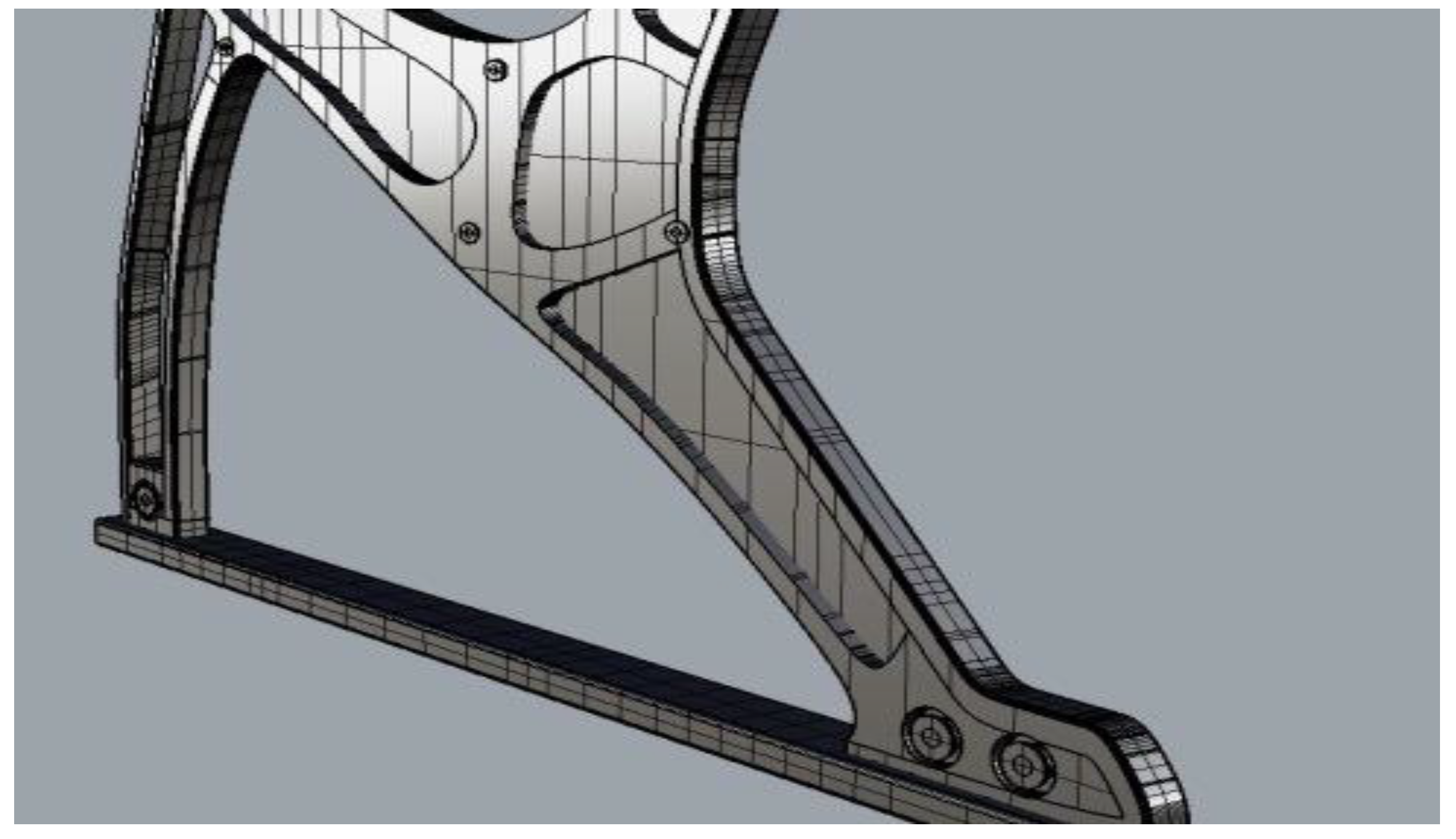
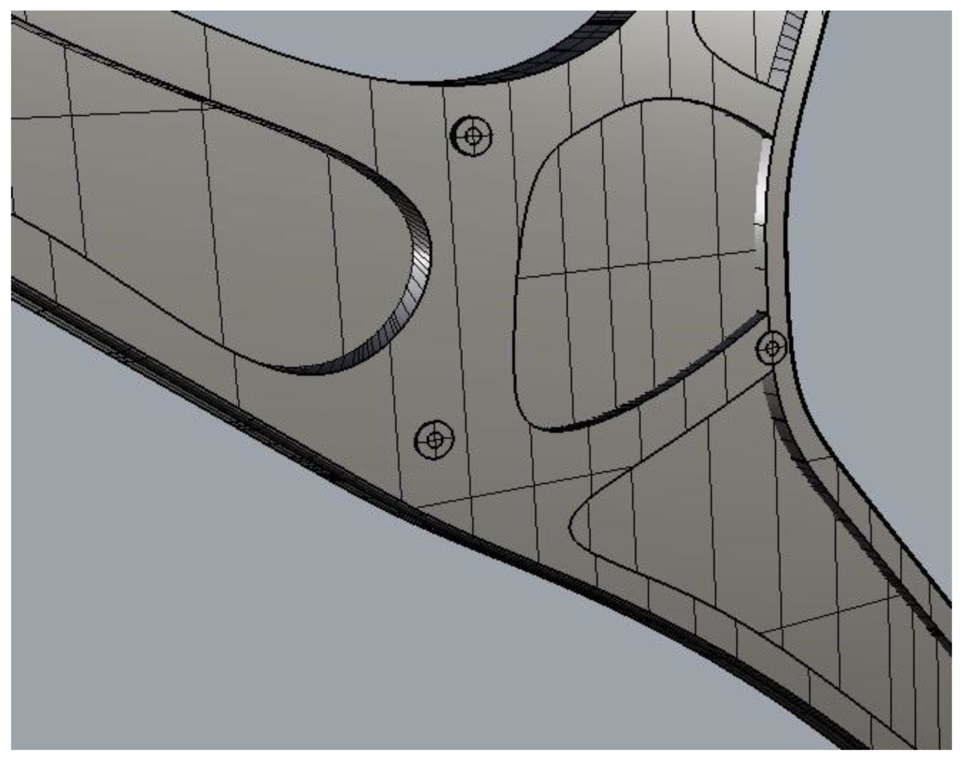
Supporting planar plate with semi hollow cut will allow the whole structure to endure larger stress through shear deformation, with about the same amount of material used. In this way, the lateral supporting structure can better utilize the material, in order to save material and be more cost-effective. Detailed structural analysis of the planner plate will be followed to better illustrate the mechanism of this design. A general idea can be found from Figure 10.
Adding additional support components, such as screws, to make all the plates a one-piece component, helps to increase the overall endurability under the 3D shear deformation, at the areas where most planner plates overlay each other. In the case of potential shear displacement between the plates, if all the components are bonded together, they will behave stronger as a whole unit, and are less likely to undergo large displacement and disassembly compared to simple structure [13]. Simulations will be shown to support this method of adding screws in the following sessions. The simple structure is shown in Figure 11 and the redesigned structure is shown in Figure 12.
Spider-shaped seat bottom bifurcation is to spread out the center of gravity and distribute it to a larger area, thereby reducing the amount of force per unit area. However, it must be soldered to the ground to ensure stability [14].
The pillars of each arch bend (or triangular) is to maximize the force that it can support. Patent US4375300 has also proven that the triangular hinge is the best structure to support maximum truss [15].
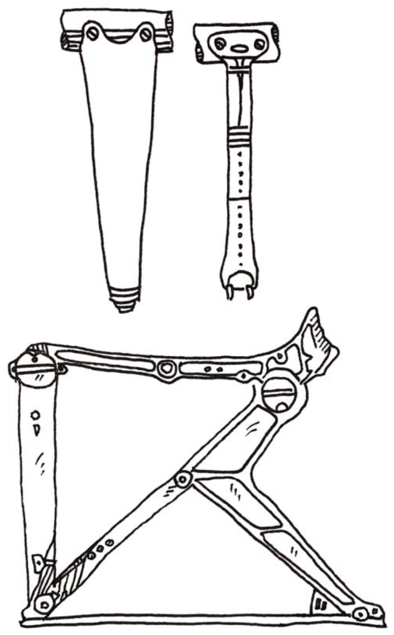
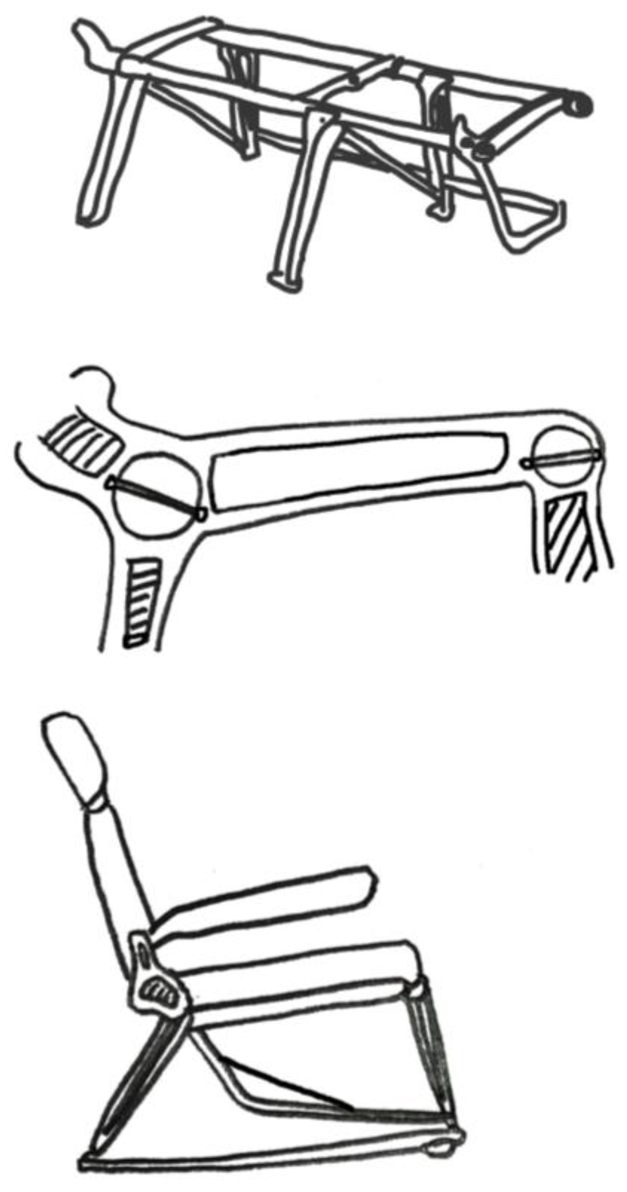
Traditional airline seat skeleton [16] has two support points, mainly on the ends of each side, with small hinges to support a large skeletal structure [8]. The traditional and redesigned structure are shown in Figure 13 and Figure 14.
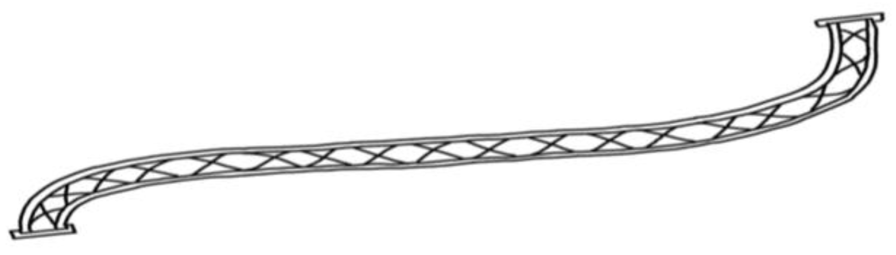
The redesign is completely opposite of the above concept as the traditional structure [17] shown in Figure 15. It focuses on minimizing the area of the skeletal structure for a larger support area. Not only does it reduce the weight of the support, but we can also provide a safer seat structure. This is through maximizing the support area to a long beam, connecting all the chairs so that the pressure from the passenger can be equally distributed to a greater area.
By changing the traditional support leg base to a stent-like support, not only does it not affect the amount of weight it can carry, but it also reduces the amount of material used and gives passengers more space allowance.
6.2. Material Mechanics
There are air holes shown in Figure 16 to minimize the volume of material used, yet the strength does not differ much [18]. It minimizes usage of materials, thus saving cost. More holes are designed to be placed on the back support rather than seat support, as the main pressure point is on the lower seat area.
6.3. Structural Analysis
6.3.1. Supporting Planar Plate
Finite Element Analysis is run for comparison of the supporting planar plate with a semi hollow cut. The hollow cut will help to enhance the structure.
The analysis is run with two supporting plates with about the same amount of material. The momentum is applied to mimic the load of a human sitting on a normal chair, as can be shown from the stress distribution plot in Figure 18 and Figure 19. When applying the hollow cut method, the maximum stress of the uniform cut plate is around twice that of the hollow plate.
The smaller stress indicates that the design with a hollow cut is structurally stronger than the uniform cut. With the similar design maximum stress, the hollow design can save much material, or, with the same amount of material applied, the hollow design can withhold a much bigger load, which increases the safety of the seat system.
The reason behind the stronger structure is that, although the material is reduced in the middle of the plate, the edges of the plate is enhanced compared with the middle area. The edge area plays a more significant role in the structure. That is why when using the same amount of material, the bending stiffness of the hollow plate will be much bigger, which can help the whole structure to endure larger load.
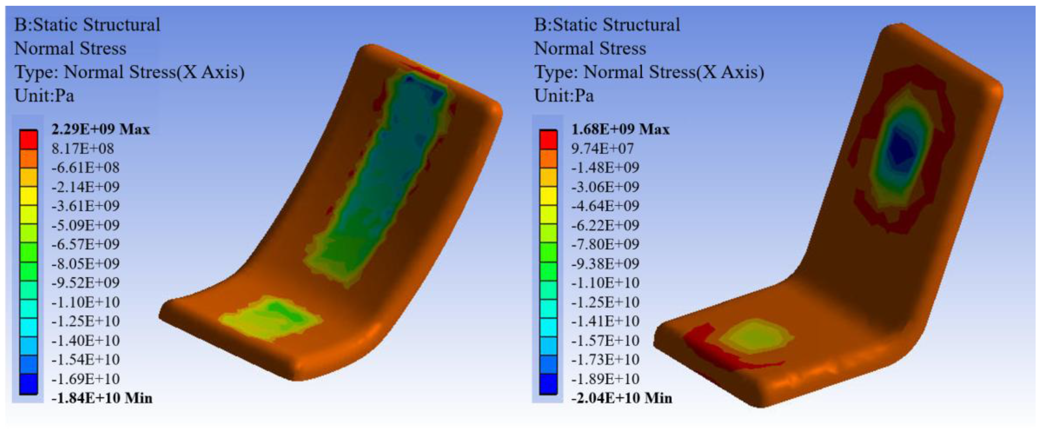
6.3.2. Screws Connecting the Supporting Plates
To implement the hollow cut design of the supporting parts, multi-layer plates will be combined to form the supporting part. Screws will be added where most planner plates are overlaid, to bond all the layers together. The screws not only physically connect all the layers, but also important in the structure. When shear force is loaded on the seats, the screws act as an essential role to withstand the shear deformation. And it will be more efficient to apply the screws at the spots with the most layers of plates. When the screws are positioned at the place with maximum number of plates, the shear stress will be more uniformly distributed to all the plates, which in effect help the entire supporting structure stronger. In addition, the more uniformly distributed shear stress is also applied to the screws themselves, makes the screws less likely to break.
Simulation is run for the screws. The results can be seen in Figure 20 and Figure 21. For comparison, both the two-layer and four-layer plates’ situations are analyzed. On the left is the stress of the screw located in the two-layer plates. On the right is the four-layer case. The same shear displacements are applied to the plates. From the stress plots of the screw, it is seen that when the screw is located at the spots with the most layers of plates, the stress on the screw is much smaller. To be more specific, the two-layer case results in stresses around one and a half times and twice the stresses for the four-layer case. In extreme cases, the screws will firstly break, and the plates will disassemble afterwards. In the new design, the safety of the screws is improved, and hence the overall stiffness of the entire supporting components will be higher under the shear load.
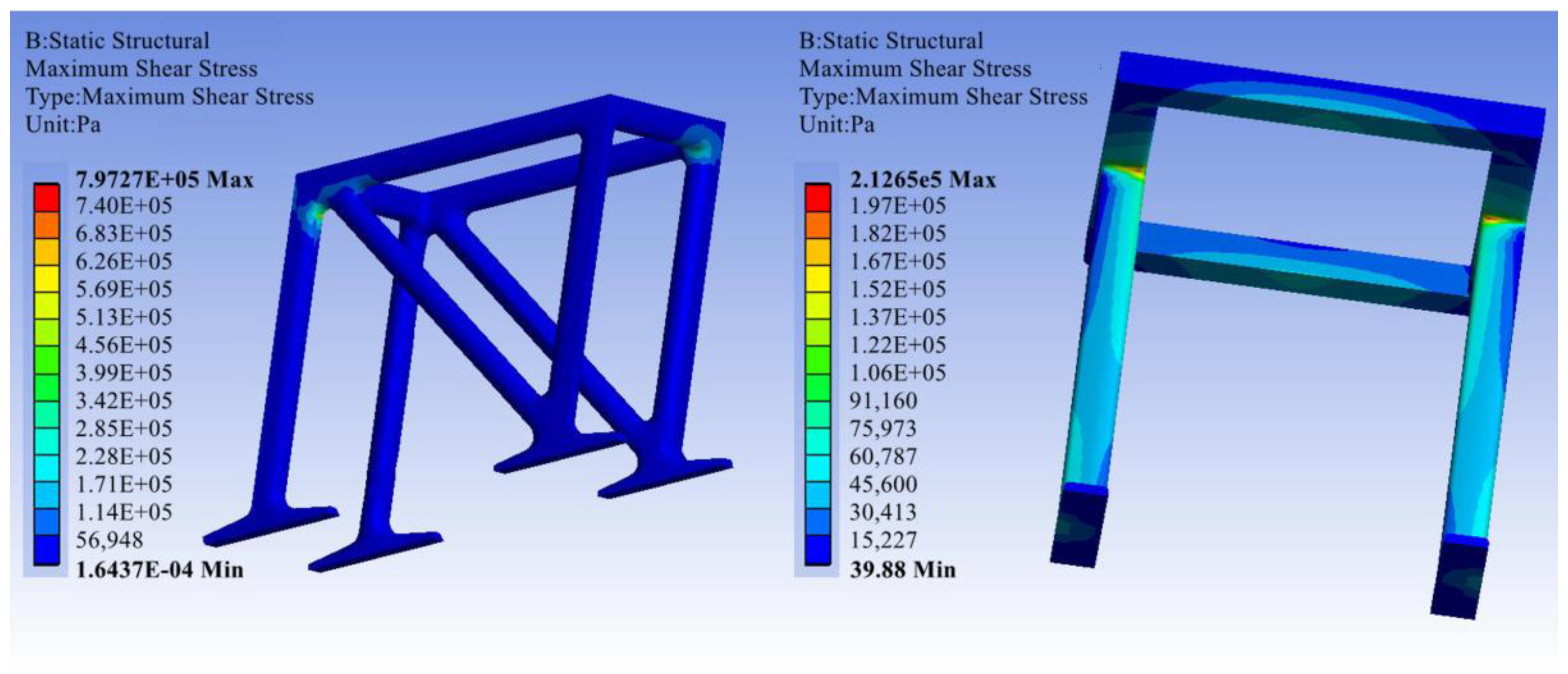
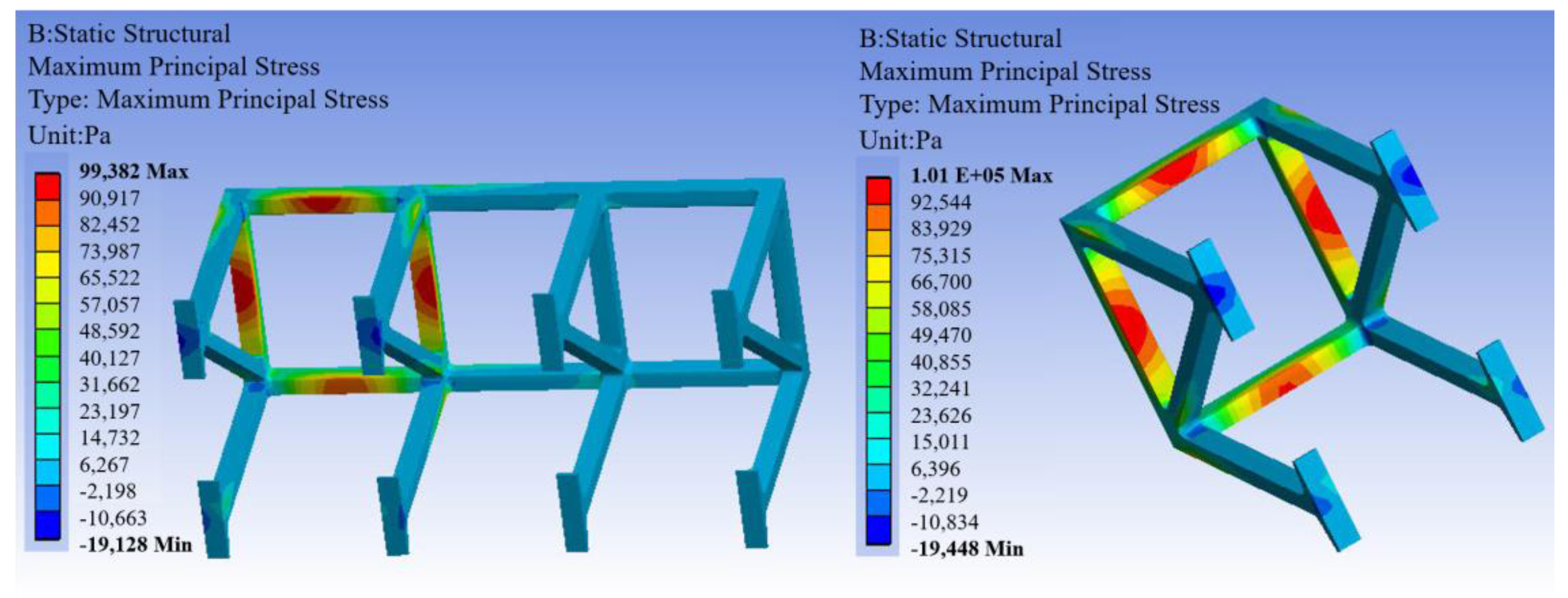
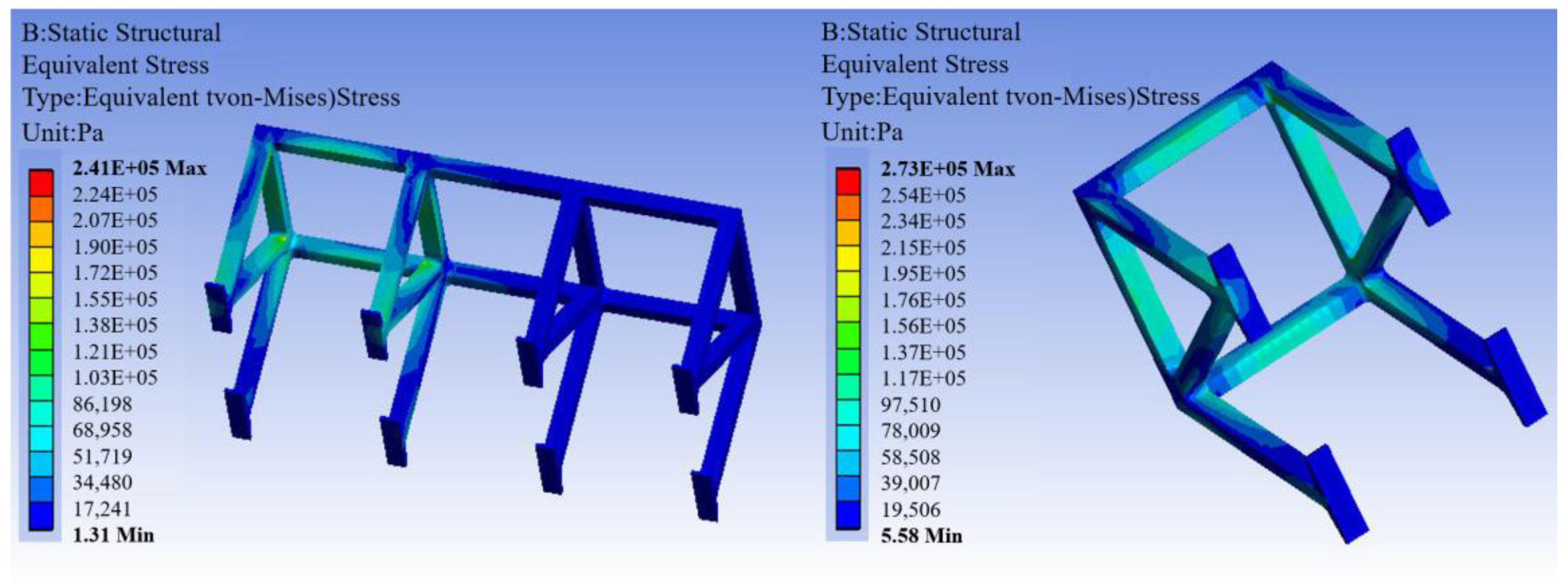
6.3.3. Triangular Hinge
The analysis for comparison of the triangular hinge and simple straight hinge is also calculated. The results are shown in Figure 22. For the truss structure, the triangular hinge can also enhance the overall stiffness, so the stability can be improved. The triangular hinge provides more contact between the chair and the ground, hence distributing some of the load from the seat.
For a simple straight hinge, as can be seen from Figure 23, it is more difficult, structurally, compared with the triangular truss, since single column support is not as stable. Otherwise, it needs to be much thicker in order to provide the same stiffness, which might not be economically efficient. It is also challenging for the junction area, where high stress is concentrated.
Different types of stress are compared to verify that the triangular hinge is more structurally reliable for the truss. As Figure 24 shows, highly concentrated stress is much less for the triangular hinge, which results from the evenly distributed loading, so that the triangular hinge can withhold higher loading in applications.
6.3.4. Chair Support
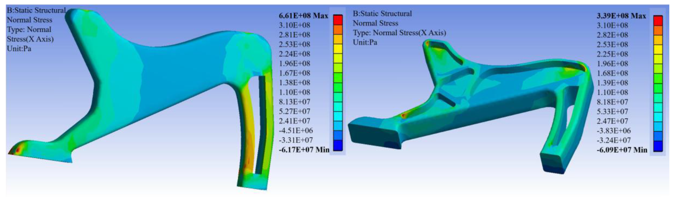
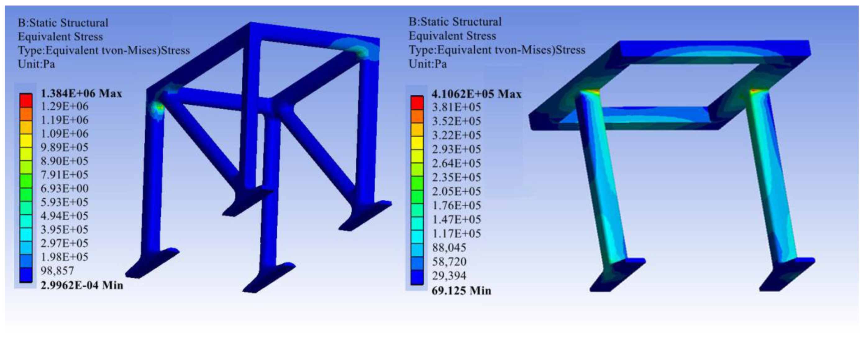
Simulation has also shown that, by using the redesign, the stress for the chair support is more uniformly distributed, and the stress is also reduced because the stiffness of the entire structure is enhanced by the redesign. Figure 25 illustrates this below. Thus, the area of the skeletal structure can be minimized for a larger support area. The smaller supporting base can also help to provide a larger space for passengers on the plane.
Different types of stress are investigated, and all results show that the support part of the redesign can perform better than the traditional design. When the adjacent chairs are connected, the whole supporting structure is united as one entity, which provides a stronger base for the seating. It can be seen from Figure 26.
6.3.5. Seat
As for the seat, it can be shown from the Finite Element Analysis that the designed chair can provide a safe protection for passengers. Stress is more uniformly distributed over the chair, compared with traditional straight chairs. Firstly, it increases the structure safety of the whole chair, just like the protected structure of the embryo from the eggshell. Secondly, the chair is more comfortable for passengers. In traditional chairs, most stress is concentrated in a small area. A passenger easily feels uncomfortable if most of the pressure is applied on one area on the back. In this case, passengers need to adjust the posture very often. However, the design here makes the shape of the chair fit to a human’s back, which can in some way adjust to a human’s skeleton structure, and provides support to the spine, especially the lower back area. Hence, the comfortableness can be much improved. The plot can be seen in Figure 27.
Different loading scenarios are applied to the seats to compare the structural performance of the redesign. Furthermore, it can be seen from the stress contour plot Figure 28, that the redesign can evenly distribute the load over the entire seat. Structural-wise, in the case of extreme loading, the redesigned seat will be less likely to break due to the even stress distribution. In addition, compared with the straight seat, the redesign can better fit the curve of the human body. Then, the passengers can have a bigger contact area between the body and the seat. The whole back will be supported, so, from ergonomics, the redesign is better for the human body. As a result, both the structural and comfortableness performance can be improved at the same time.
6.4. Weight
6.4.1. Structural Mechanics
Reducing materials in some unnecessary areas is useful to save on material costs while providing about the same level structural support. More importantly, the weight of the heaviest part of the structure can be decreased. As Figure 29 shows, the hollow structure can save material without sacrifice the strength.
6.4.2. Material Mechanics
Composite materials are used by aircraft to achieve significant weight reductions compared to conventional seat systems [18]. The seat assembly consists of a lightweight composite support structure, a lightweight composite seat base, and also a seat back assembly with a lightweight inner frame.
The take away message from this patent is that composite materials are one of the fields that require more research. The materials known as advanced polymer matrix composites have the potential to be the best material to construct the skeletal structure with lighter weight. Figure 30 gives a general idea of the material.
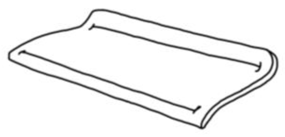
The sponge foam cushion has air holes inside. The shape of the cushion changes according to the back shape of each user, maximizing comfort and, at the same time, minimizing the materials used [20], as shown in Figure 31 and Figure 32. The inflatable mattress variant degree has been calculated to ensure that the basic shape can provide ergonomic uses [18].
Seats can use the support from carbon fibre tubes and do not require additional metal support structures [13], shown in Figure 32.
Upholstered carbon fibre tube support and cushion foam structure are constructed with half of the sponge (foam) [14] in order to achieve a comfortable seating position, saving on material, shown in Figure 33.
Forward thigh support structure is higher than back seat support, as it can provide more leg space for the users. Using Y shape support for the back structure (honeycomb) can also reduce the weight of the whole seat structure, yet provide approximately the same weight support [11], shown in Figure 34.
From this, it was concluded that honeycomb material reduces the total weight of support structure, yet is able to support about the same pressure as the original design. It is both light and strong.
6.5. Cost
6.5.1. Material Mechanics
The material cost could be optimized by minimizing the usage of materials and choosing the most economical yet strongest material, as Figure 35 shows. The costs might be reduced by removing unnecessary material. As shown in material and structural mechanics, it is able to reduce the material used without reducing much of the load that the skeleton can hold. The choice of materials for both the exterior and interior components will be further shown in the following sections.
6.5.2. Structural Mechanics
On the structural side, by reducing the amount of area of the skeleton support, like Figure 36 and Figure 37 show, both the material usage and the cost might both be minimized. On a side note, the strength of structure should not be sacrificed for the sake of minimizing material cost, as safety is the most crucial factor. Hence, by analyzing all the possible designs in strength supports and modifying them to our needs, a stable low-cost structure could be created.
7. Functionality—Reception of Information from Humans through Movements in Multiple Environments
In addition, the new design lets the seat system have more functionality through the movement of the human.
8. Conclusions
In this article, an ergonomically and human–computer interaction re-optimized design used for airplanes or similar conditions is described. The redesigned aesthetics and visual modeling part is highlighted for people to receive visual input. In addition, the ergonomics part is addressed, for a person to get a tactile signal, and a new user’s action innovation is shown for people to communicate, the redesign of the structure of the system features with stronger structure and low weight and cost, and the functional system environment is illustrated for people to get information from human movement. Structural analysis is detailed to support the design. It can be seen that, with new tech, the ergonomics and interaction HCI system is improved for the seat’s system.
In this paper, human machine engineering and interaction and their relationship in seating design are discussed from different angles, including the design methodology. The methodology starts from concept-driven design. In the early stage design concepts, some elements from some certain objects are extracted and applied in the seating system, and then integrate multiple objects to construct the new characteristics of the product. This methodology combines the features of multiple objects in the human–machine interaction. In order to meet some certain user needs, the essential factors are taken from objects with the functions needed, and integrated into the product to implement the function, and then the design goal is met.
In this paper, ergonomics in the seating design are discussed from multiple aspects, including methodology of design constituted. This methodology is generally identified with design deconstruction and design reconstruction. By deconstructing the key factors of points, lines, and surfaces, and reconstructing them again, some more sophisticated designs can be obtained. In addition, from the rapid iteration of tests or vote-type design, some effective schemes can be developed, with improved features from original scheme. Furthermore, these features can effectively affect the user needs when using the seating system. Thereby, the optimization from another methodology in the seating ergonomics can be achieved.
Future work may put emphasis on more efficient human–computer interaction and more comfortable user experience for the seats. New material might be explored to provide lighter weight, without decreasing the structural reliability.
Acknowledgments
We thank MDPI for comments that greatly improved the manuscript.
Author Contributions
Jin Cao drafted the initial design and the iterations; Da Ku and Jiachun Du conducted structural analysis for all the parts; Weiqiao Dong and Vera Ng contributed to the research and data collection for analysis and optimization, Jin Cao, Da Ku, Weiqiao Dong and Yufei Wang organized all the data and writing.
Conflicts of Interest
The authors declare no conflict of interest.
References
- Christopher, W. Human Performance Modeling: HP2—Using Empirical Research and Human Performance Modeling to Predict Astronaut Performance in Long-Duration Space Missions. In Proceedings of the Human Factors and Ergonomics Society 2014 Annual Meeting, Chicago, IL, USA, 27–31 October 2014; pp. 834–838. [Google Scholar]
- Cao, J.; Wang, Y. An intelligent seat’s system for better ergonomics and Human–Computer Interaction. In Proceedings of the 2015 the Second International Conference on Advanced Technology and Business, Dalian, Liaoning, China, 28 December 2015. [Google Scholar] [CrossRef]
- Rosson, M.B. Affective HCI and Emotions and Motivational Aspects. In Proceedings of the IFIP INTERACT’15: Human–Computer Interaction Part I, Bamberg, Germany, 14–18 September 2015; pp. 201–209. [Google Scholar]
- Peter, W. Exploring Gesture Sinification to Support Reflective Craft Practice, What Do I Hear? Communicating with Sound. In Proceedings of the ACM CHI’15 33rd Annual ACM Conference on Human Factors in Computing Systems, Seoul, Korea, 18–23 April 2015; Volume 1, pp. 67–76. [Google Scholar]
- Kandinsky, V. Kandinsky’s Study of Point Line and Surface; Renmin University of China Press: Beijing, China, 2003; pp. 61–62. ISBN 9787300048918. [Google Scholar]
- Stewart, J.R.; Mathieson, A.N.; Ecay, T.W.; Herbert, J.F.; Parker, S.L.; Thompson, M.B. Uterine and eggshell structure and histochemistry in a lizard with prolonged uterine egg retention (Lacertilia, Scincidae, Saiphos). J. Morphol. 2010, 271, 1342–1351. [Google Scholar] [CrossRef] [PubMed]
- Lee, D.H. An Outlook for Content UX in TV: The Emergence of Augmented Content. In Proceedings of the ACM CHI’15 33rd Annual ACM Conference on Human Factors in Computing Systems, Seoul, Korea, 18–23 April 2015; Volume 2, pp. 789–796. [Google Scholar]
- Kim, D. User Situation-Aware Mobile Communication Method. In Proceedings of the HCI International 2015 17th International Conference on HCI: Posters’ Extended Abstracts, Part II, Los Angeles, CA, USA, 2–7 August 2015; Volume 5, pp. 508–513. [Google Scholar]
- André, R.F.; Vuyk, H.D.; Ahmed, A.; Graamans, K.; Nolst Trenité, G.J. Correlation between subjective and objective evaluation of the nasal airway. A systematic review of the highest level of evidence. Clin. Otolaryngol. 2009, 34, 518–525. [Google Scholar] [CrossRef] [PubMed]
- Johnson, P.W. Differences in the three-dimensional typing forces between short and long travel keyboards. In Proceedings of the Human Factors and Ergonomics Society 2014 Annual Meeting, Chicago, IL, USA, 27–31 October 2014; pp. 1447–1450. [Google Scholar]
- Chen, X. The Application and Finite Element Analysis of Magnesium Alloy on Automobile Seat Structures. Master’s Thesis, Jilin University, Changchun, China, 2006. [Google Scholar]
- Francis, P.; McCullough, R., Jr.; Snelgrove, V.; Goswami, B.C. Flame Retardant Composite Polymeric Foams. Patent EP0327170A2, 9 August 1989. [Google Scholar]
- Fei, F. A Study of the Relation between the Adjustable Dimensions of Automobile Seat and Driving Comfort. Master’s Thesis, Nanjing Forestry University, Nanjing, China, 2011. [Google Scholar]
- Wang, J.C.; Huang, H.; Liu, X.T.; Zhao, L.H.; Tao, Y.L. Lightweight Design of Automotive. J. Shanghai Univ. Eng. Sci. 2011, 26, 15–18. [Google Scholar]
- Miyazaki, Y.; Hashimoto, K.; Kuriyama, Y.; Kobayashi, J. Welding Methods and Forming Characteristics of Tailored Blanks (TBs); Nippon Steel Technical Report No. 88 July 2003; UDC 629.11.011:621.791.72:621.983; Nippon Steel & Sumitomo Metal Corporation: Tokyo, Japan, 2003; pp. 35–39. [Google Scholar]
- Yang, T. Optimal Design on Structure and Forming Process for Lightweight of Automobile Seat. Int. Appl. Eng. Res. 2012, 12, 1855–1859. [Google Scholar]
- Yuan, S. Comfort of automobile seat. Automob. Sci. Technol. 1990, 2, 12–16. [Google Scholar]
- Zou, B. The Design of Comfort of Automobile Seat Based on Ergonomics. Automob. Sci. Technol. 2009, 4, 15–17. [Google Scholar]
- Feng, F.Y.; Hou, J.J. The Design of Resistance to Fatigue Automobile Seat Based on Ergonomics. Mech. Manag. Dev. 2010, 25, 16–17. [Google Scholar]
- Ling, L. Research on Subjective and Objective Evaluation Method of Automobile Seat Static Comfort Level. Master’s Thesis, Jilin University, Changchun, China, 2012. [Google Scholar]
Figure 1.
Sketches of the design concept.
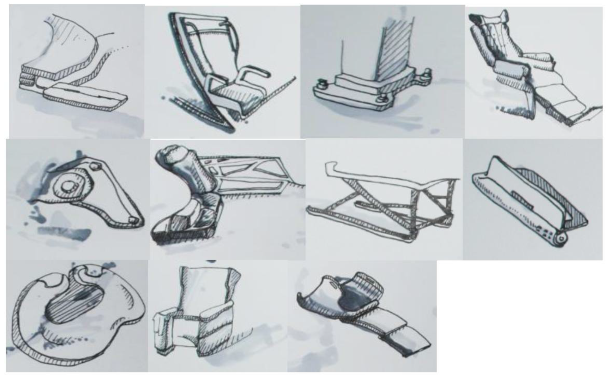
Figure 2.
Illustration of Kandinsky’s theory of point line and surface [5].
Figure 2.
Illustration of Kandinsky’s theory of point line and surface [5].
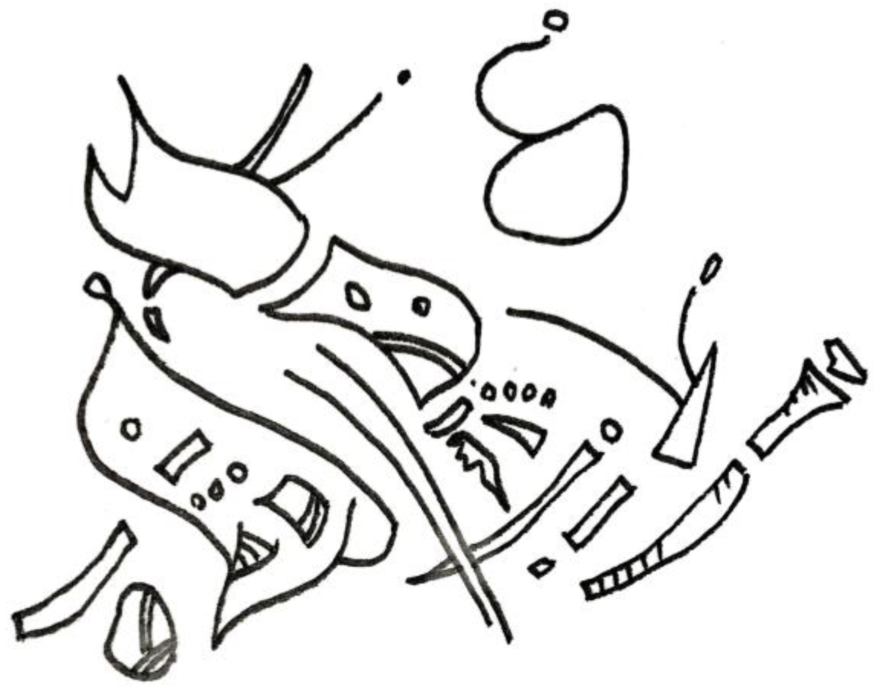
Figure 3.
Repeated pattern of lines.
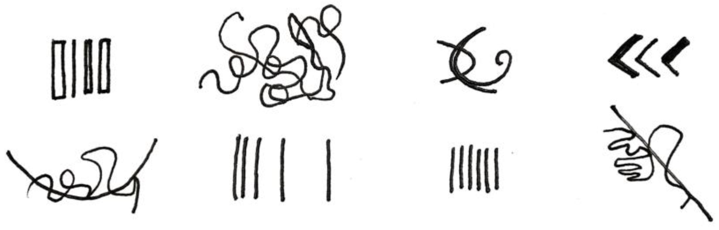
Figure 4.
3D modeling design.
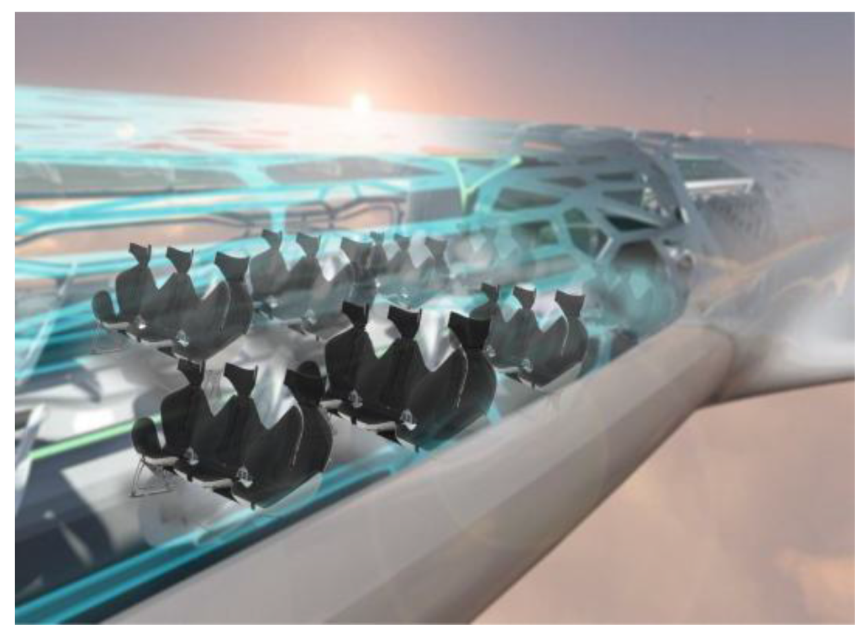
Figure 5.
Eggshell.

Figure 6.
Eggshell inspired design.
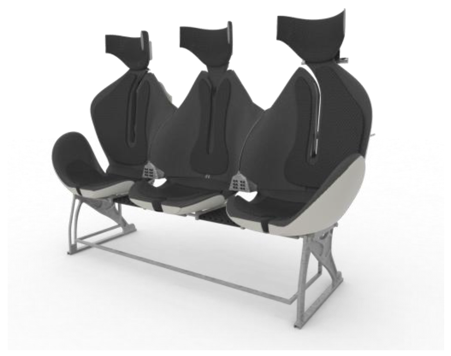
Figure 7.
Sensors installed behind the cushion.
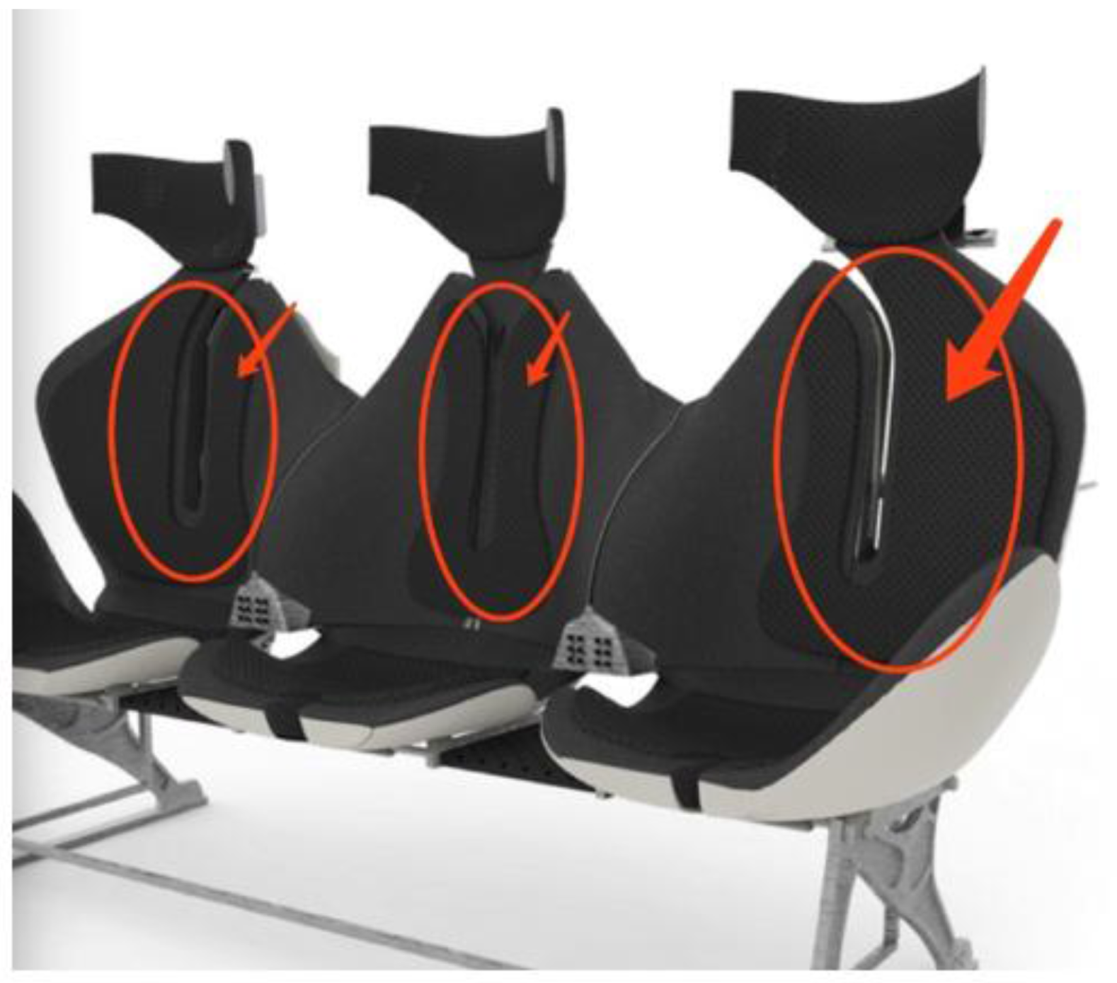
Figure 8.
The challenge of Soli was to shrink the radar to the size of a computer chip. Peter Mccollough for Wired.
Figure 8.
The challenge of Soli was to shrink the radar to the size of a computer chip. Peter Mccollough for Wired.

Figure 9.
Simple structure and redesign.
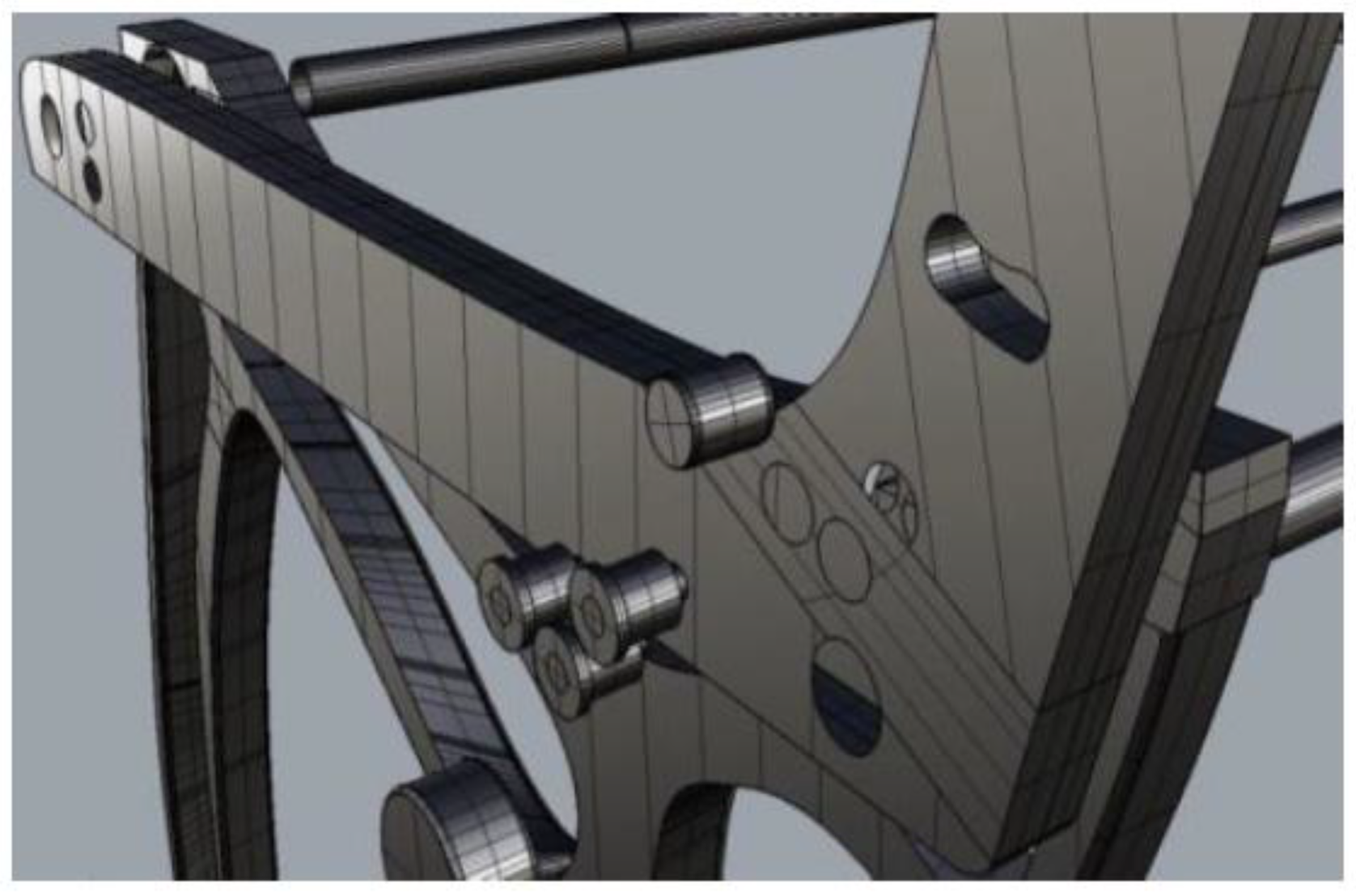
Figure 10.
Redesigned structure.

Figure 11.
Simple structure [14].
Figure 11.
Simple structure [14].

Figure 12.
Redesigned structure.

Figure 13.
Traditional skeletal structure support.
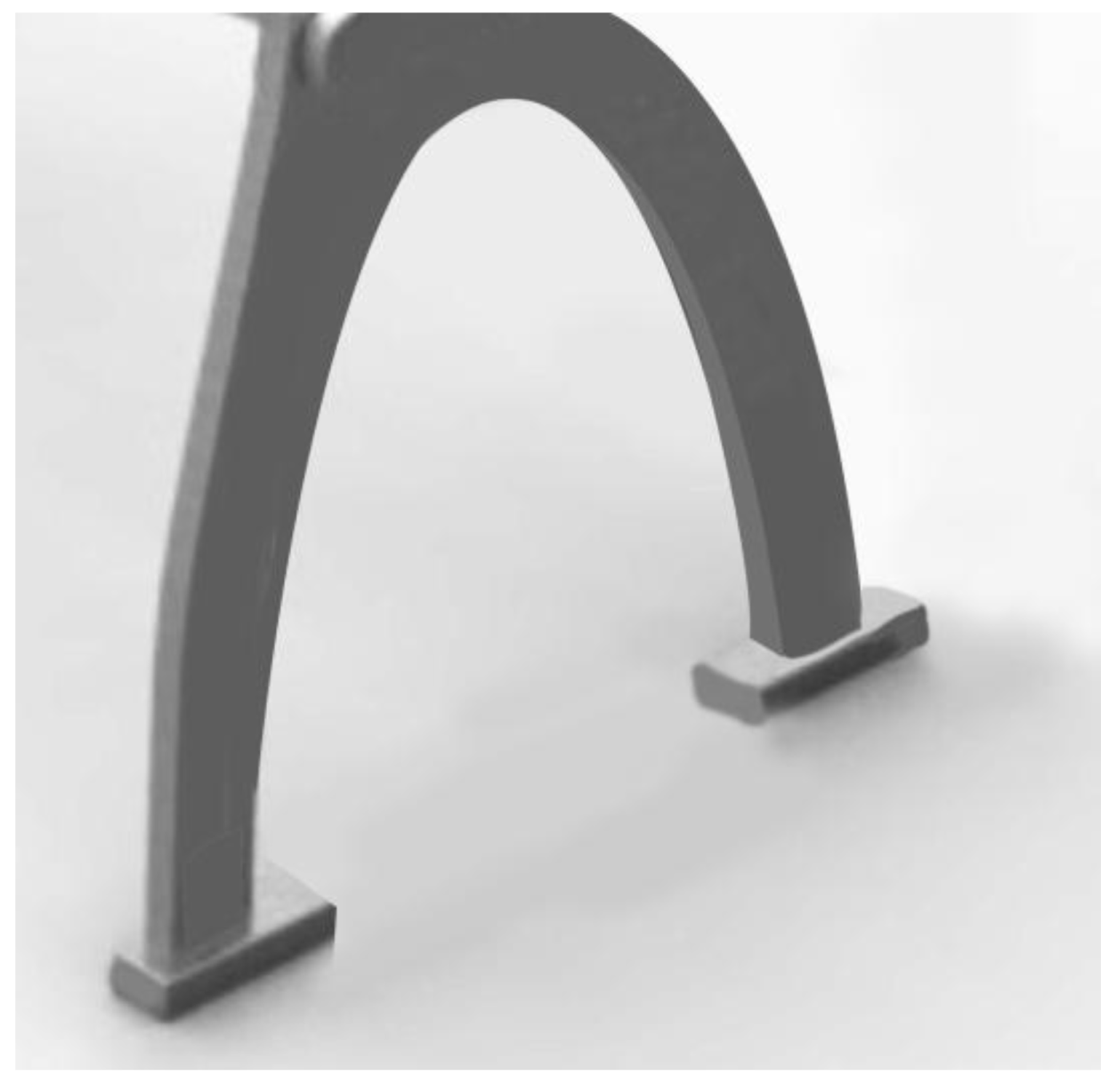
Figure 14.
Redesigned structure with reinforced support.

Figure 15.
US Patent 4,375,300 STraditional strong triangular support structure [17].
Figure 15.
US Patent 4,375,300 STraditional strong triangular support structure [17].

Figure 16.
US Patent 8,376,462 B2 Aircraft seat with holes on the back [18].
Figure 16.
US Patent 8,376,462 B2 Aircraft seat with holes on the back [18].
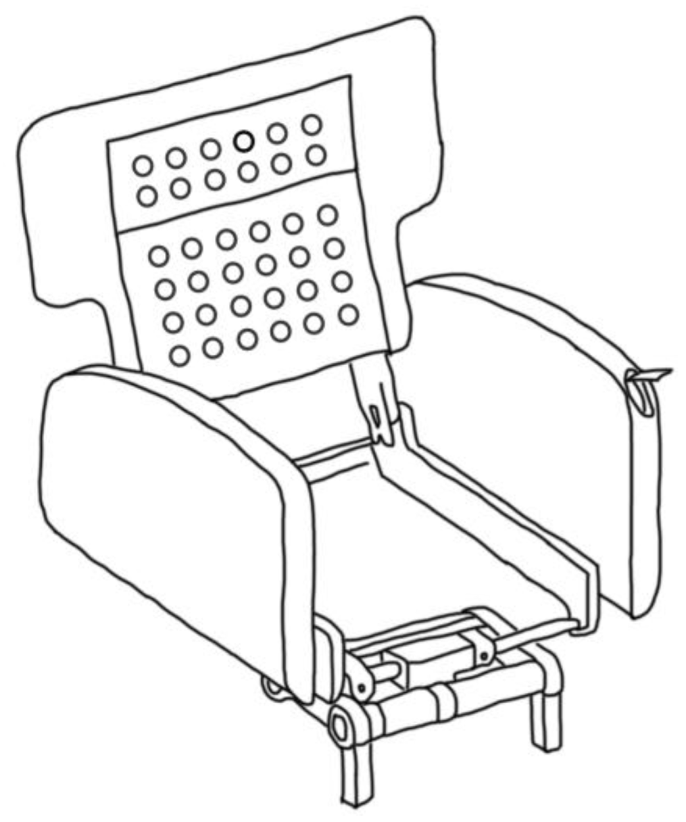
Figure 17.
U.S. Patent 4,229,040 Triangular support saves cost and materials [19].
Figure 17.
U.S. Patent 4,229,040 Triangular support saves cost and materials [19].

Figure 18.
Stress analysis for comparison of the supporting planar plate (maximum principal stress).
Figure 18.
Stress analysis for comparison of the supporting planar plate (maximum principal stress).

Figure 19.
Stress analysis for comparison of the supporting planar plate (maximum shear stress).
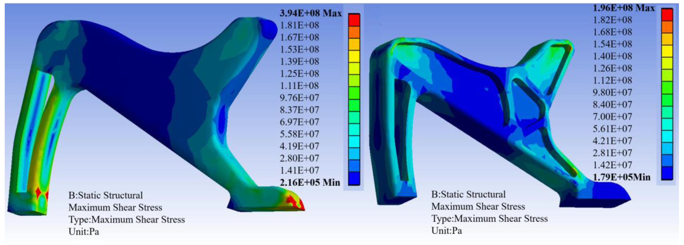
Figure 20.
Stress analysis for comparison of the screws (equivalent stress).
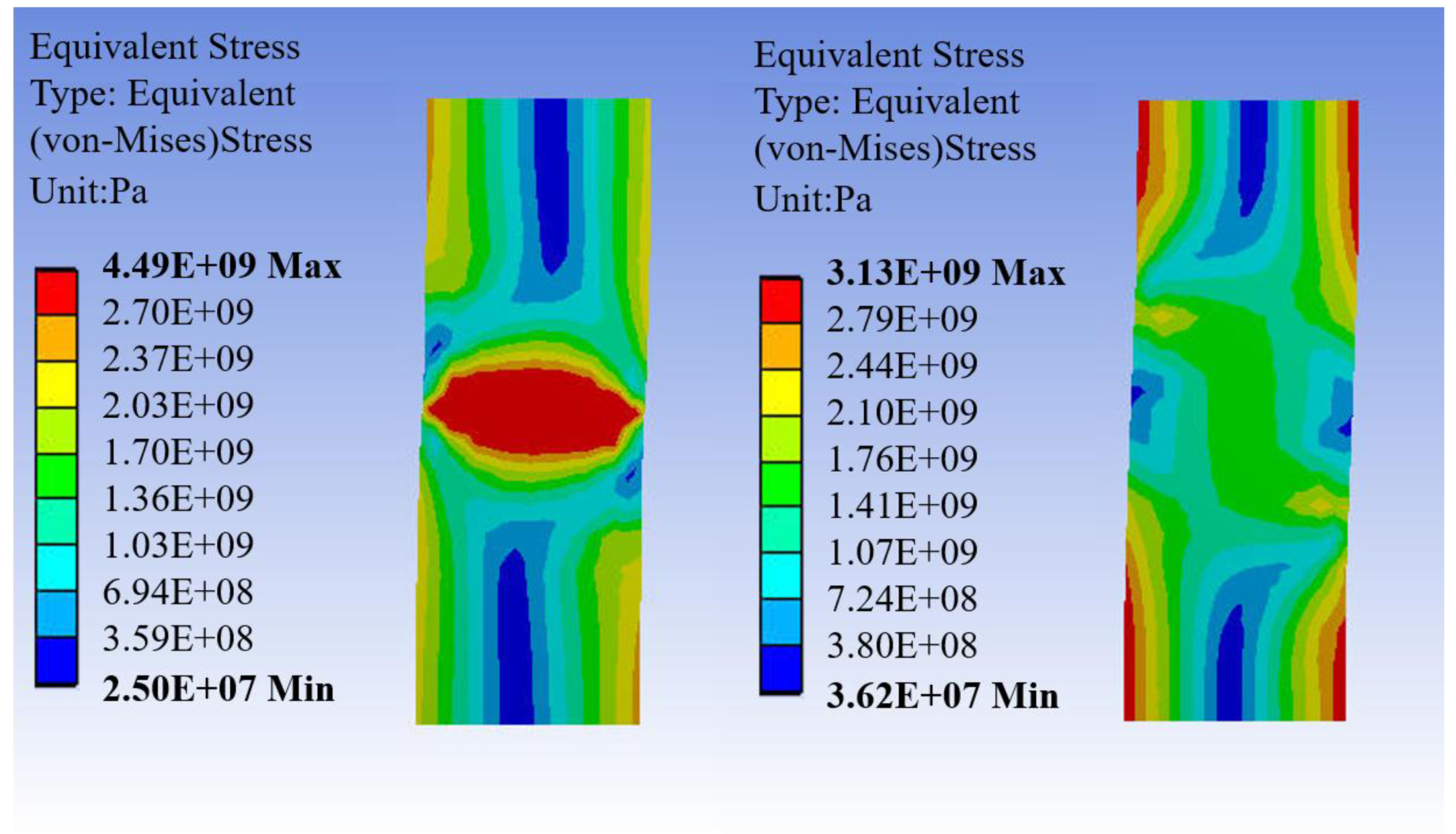
Figure 21.
Stress analysis for comparison of the screws (normal stress).
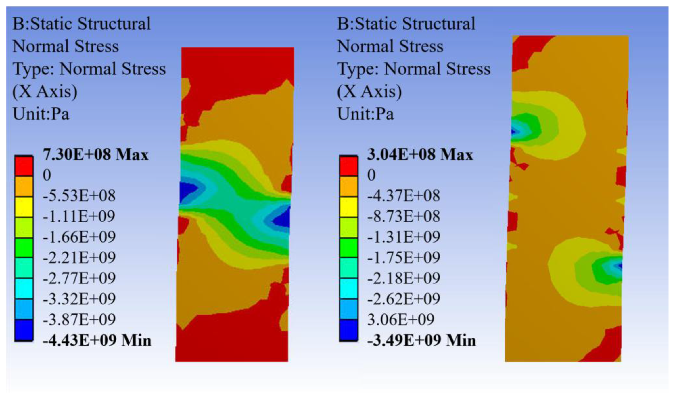
Figure 22.
Stress analysis for comparison of the triangular hinge and simple straight hinge (equivalent stress).
Figure 22.
Stress analysis for comparison of the triangular hinge and simple straight hinge (equivalent stress).

Figure 23.
Stress analysis for comparison of the triangular hinge and simple straight hinge (maximum shear stress).
Figure 23.
Stress analysis for comparison of the triangular hinge and simple straight hinge (maximum shear stress).

Figure 24.
Stress analysis for comparison of the triangular hinge and simple straight hinge (stress intensity).
Figure 24.
Stress analysis for comparison of the triangular hinge and simple straight hinge (stress intensity).
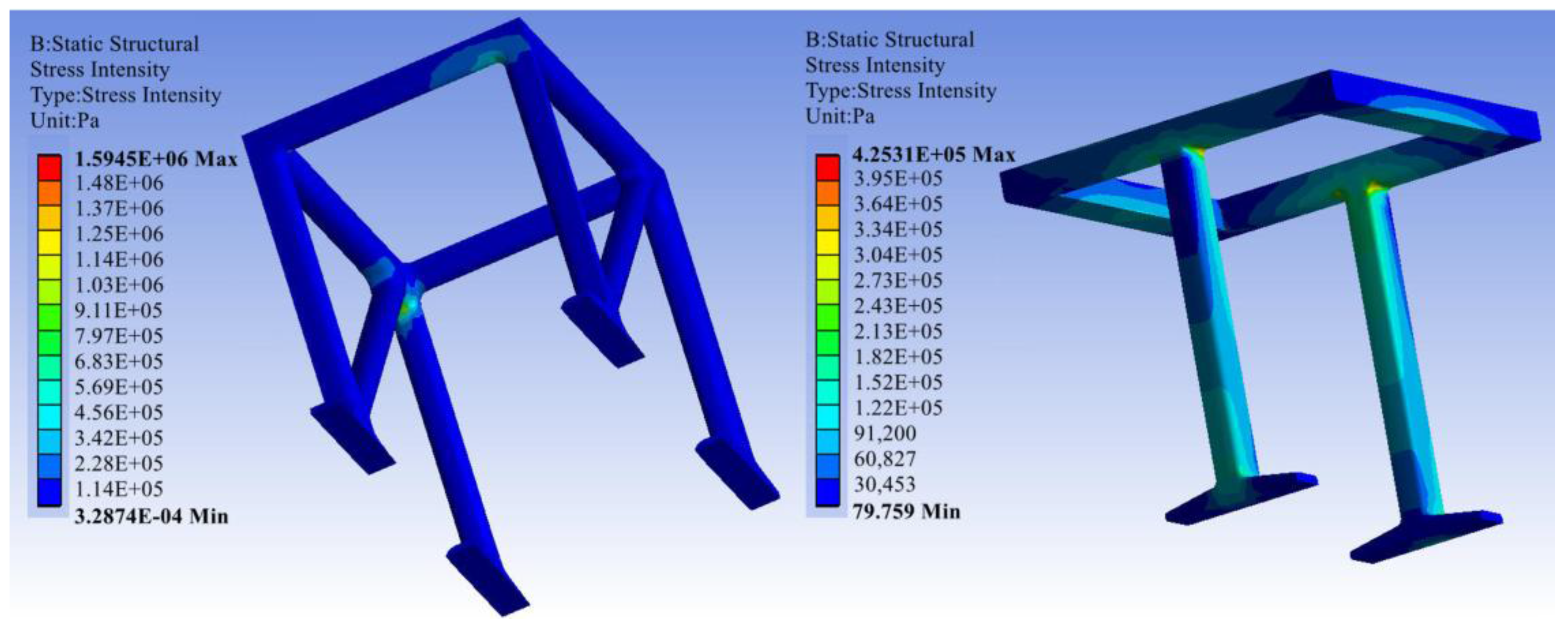
Figure 25.
Stress analysis for comparison of the support parts between redesign and the traditional support.
Figure 25.
Stress analysis for comparison of the support parts between redesign and the traditional support.

Figure 26.
Stress analysis for comparison of the support parts between redesign and the traditional support.
Figure 26.
Stress analysis for comparison of the support parts between redesign and the traditional support.

Figure 27.
Stress analysis for comparison of the chair.
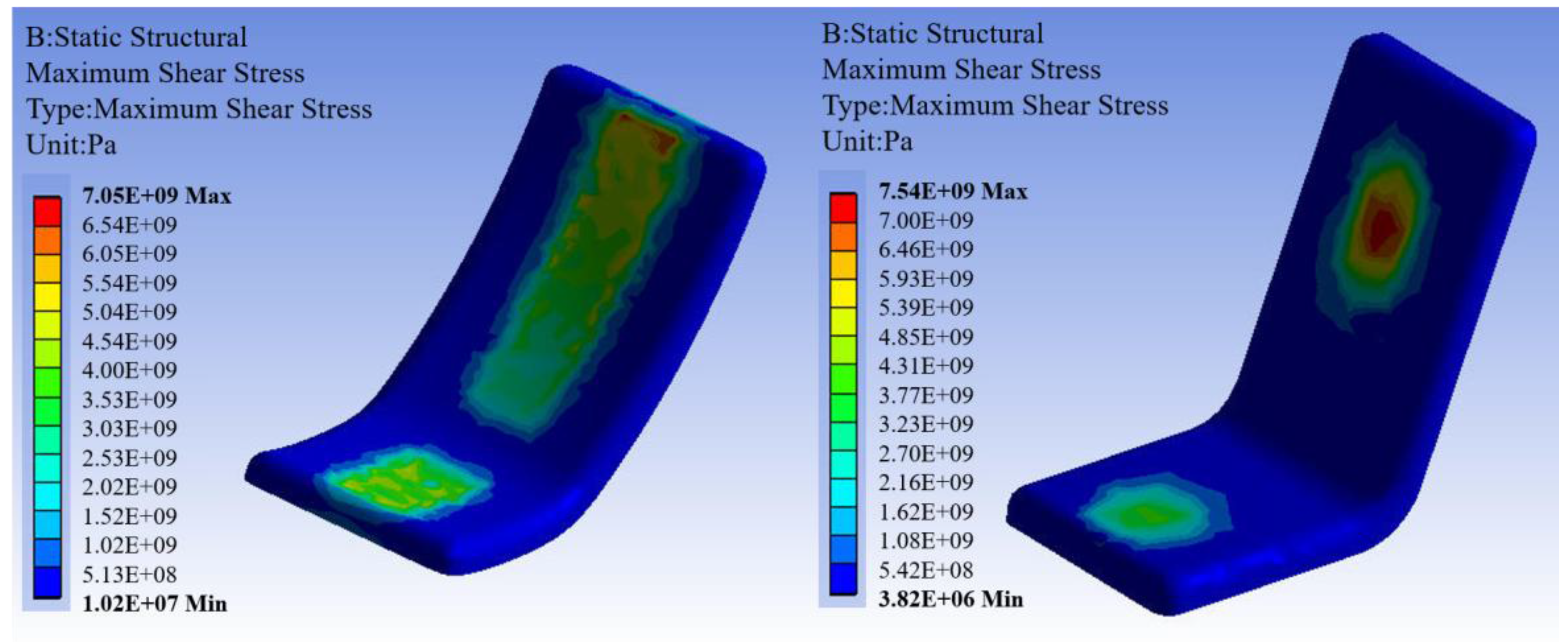
Figure 28.
Stress analysis for comparison of the chair.

Figure 29.
Structure of hollows.

Figure 30.
US Patent 007,954,762 B2 light yet strong material [18].
Figure 30.
US Patent 007,954,762 B2 light yet strong material [18].
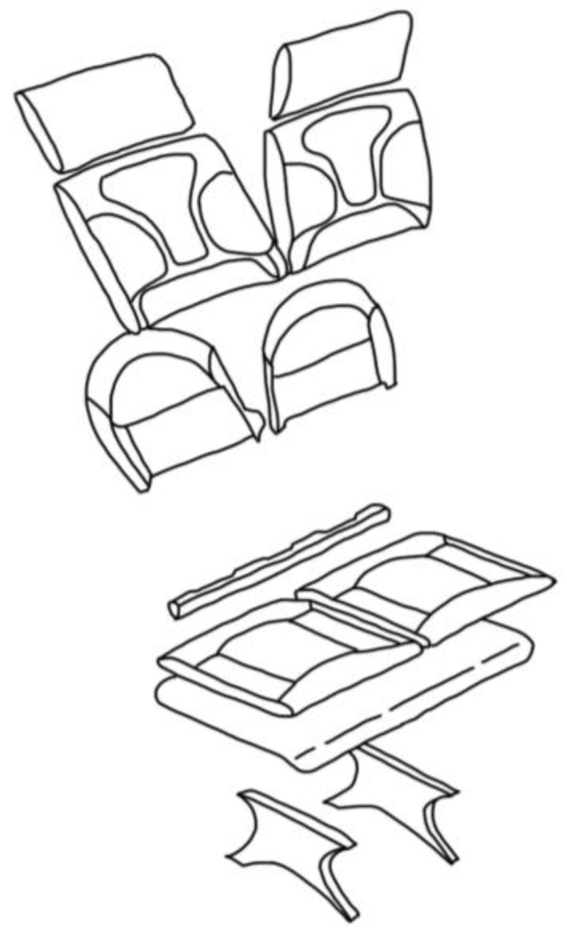
Figure 31.
US Patent 5,660,438 Seat cushion [20].
Figure 31.
US Patent 5,660,438 Seat cushion [20].

Figure 32.
US Patent 007,954,762 B2 Carbon fibre tube as a metal structure [13].
Figure 32.
US Patent 007,954,762 B2 Carbon fibre tube as a metal structure [13].

Figure 33.
US Patent 007,954,762 B2 Carbon fibre tube as a metal structure [14].
Figure 33.
US Patent 007,954,762 B2 Carbon fibre tube as a metal structure [14].

Figure 34.
US Patent 3,468,582 Honeycomb structure [16].
Figure 34.
US Patent 3,468,582 Honeycomb structure [16].
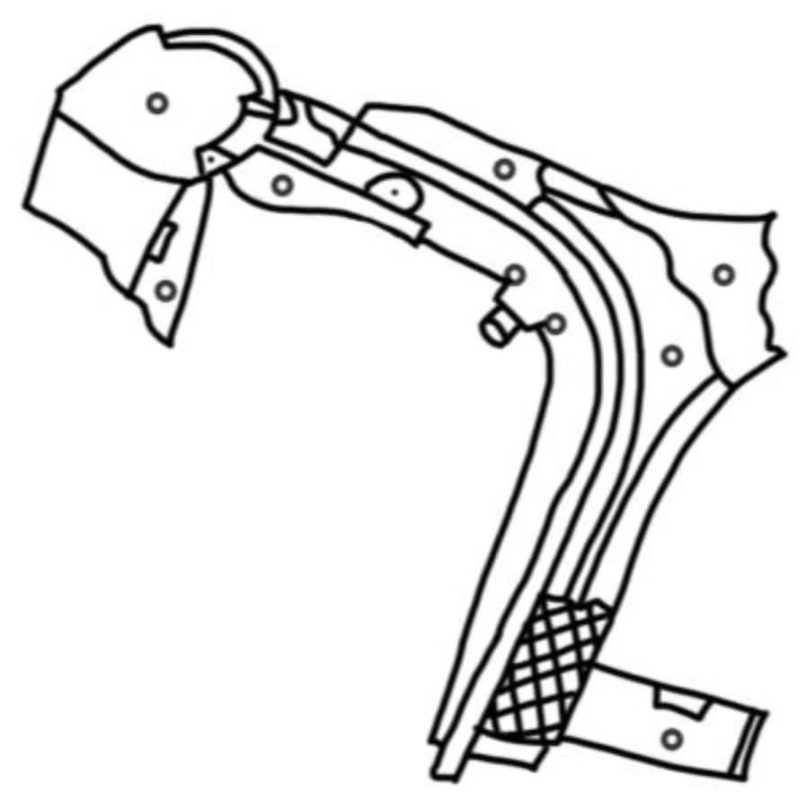
Figure 35.
Material and cost saving new design.

Figure 36.
Individual back components.
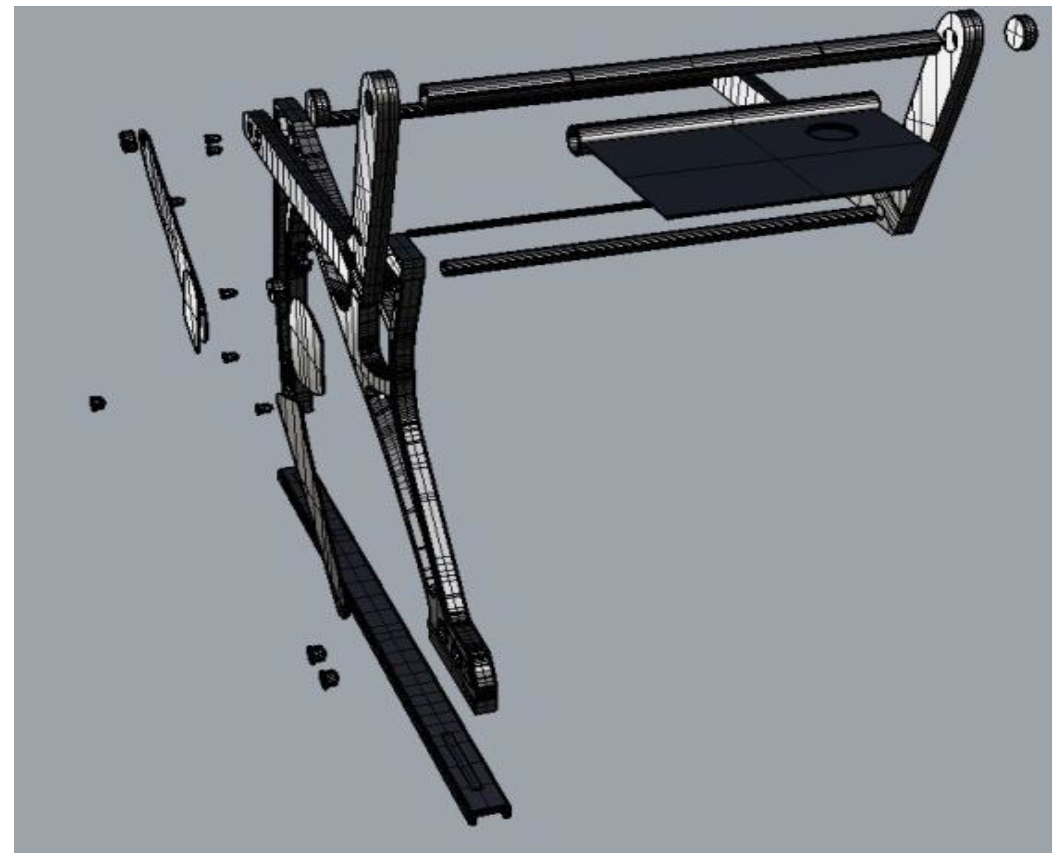
Figure 37.
Individual front components.
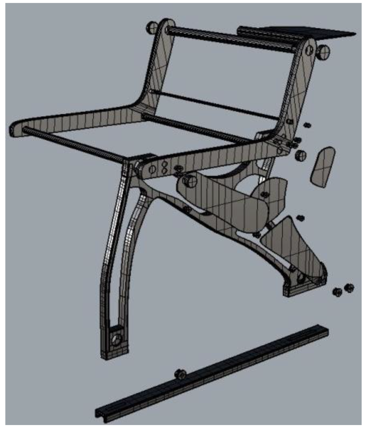
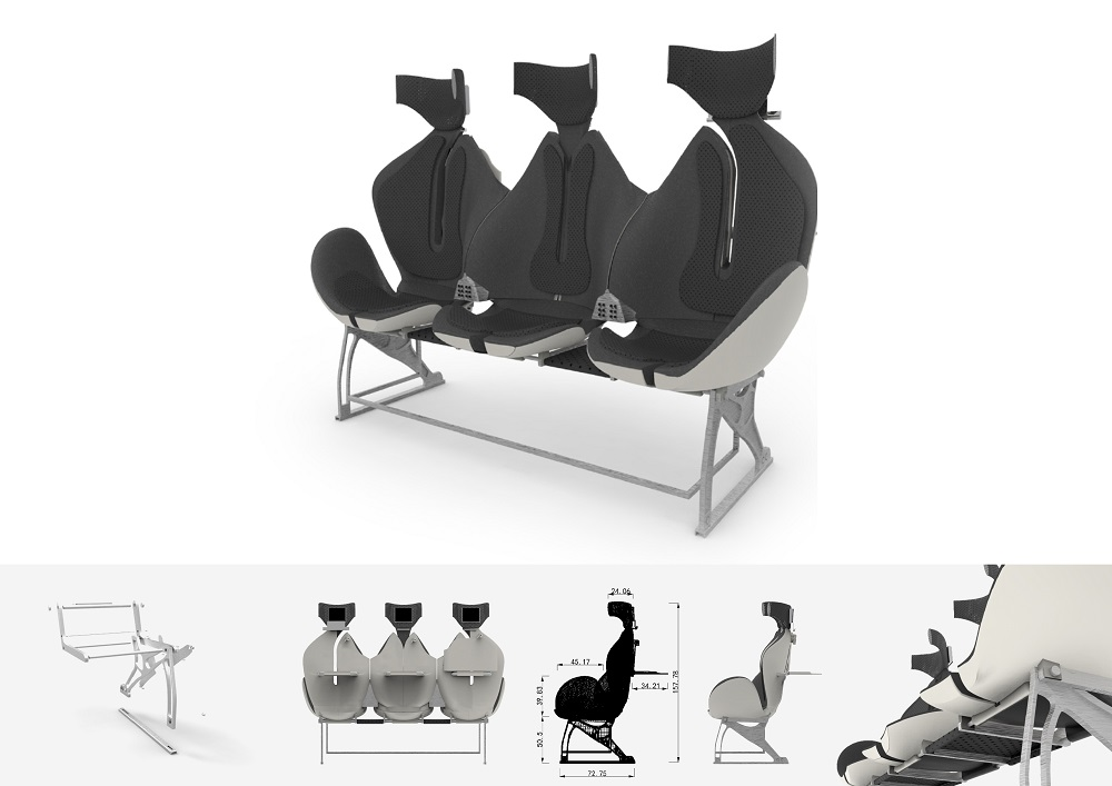
Figure 38.
Front dimension.
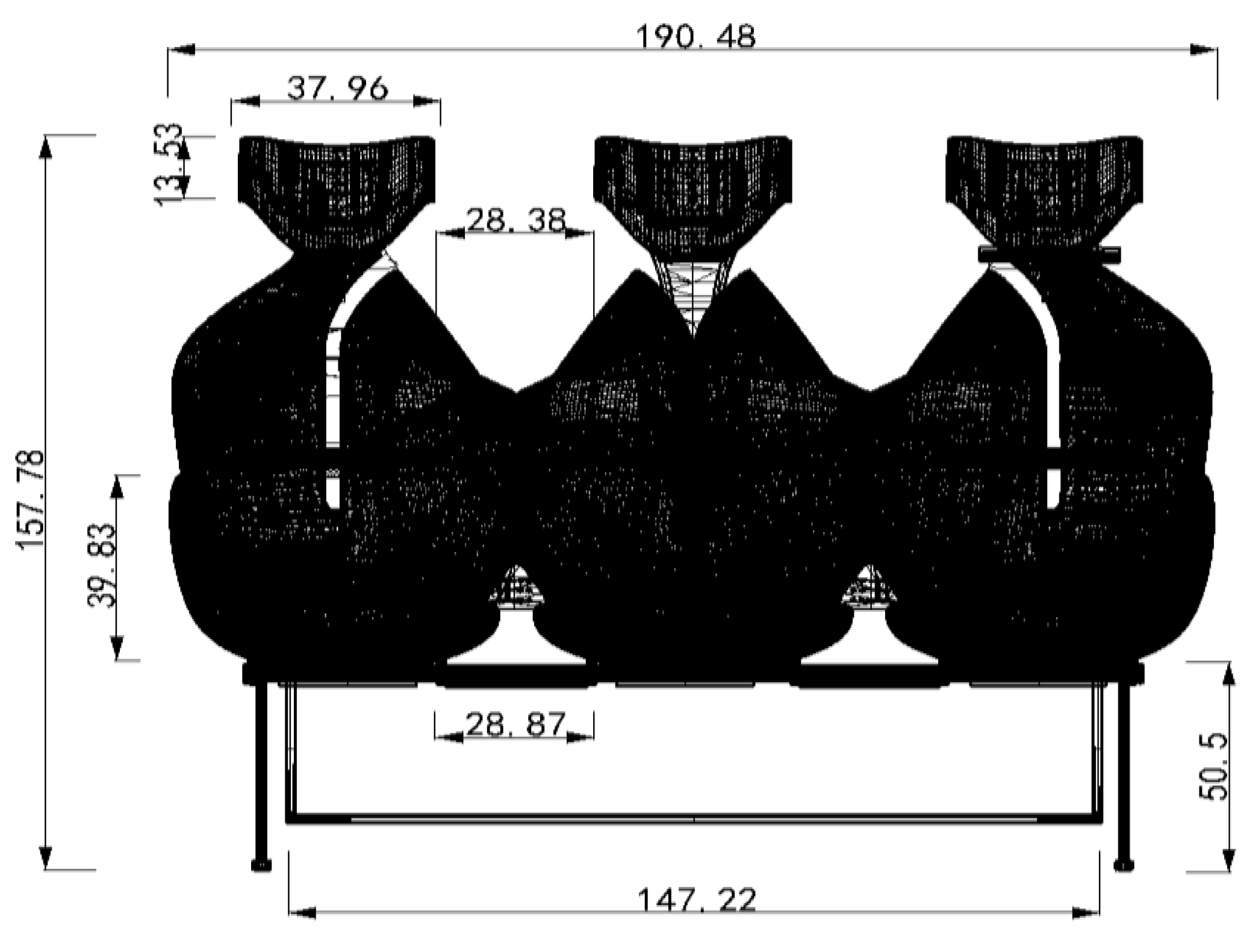
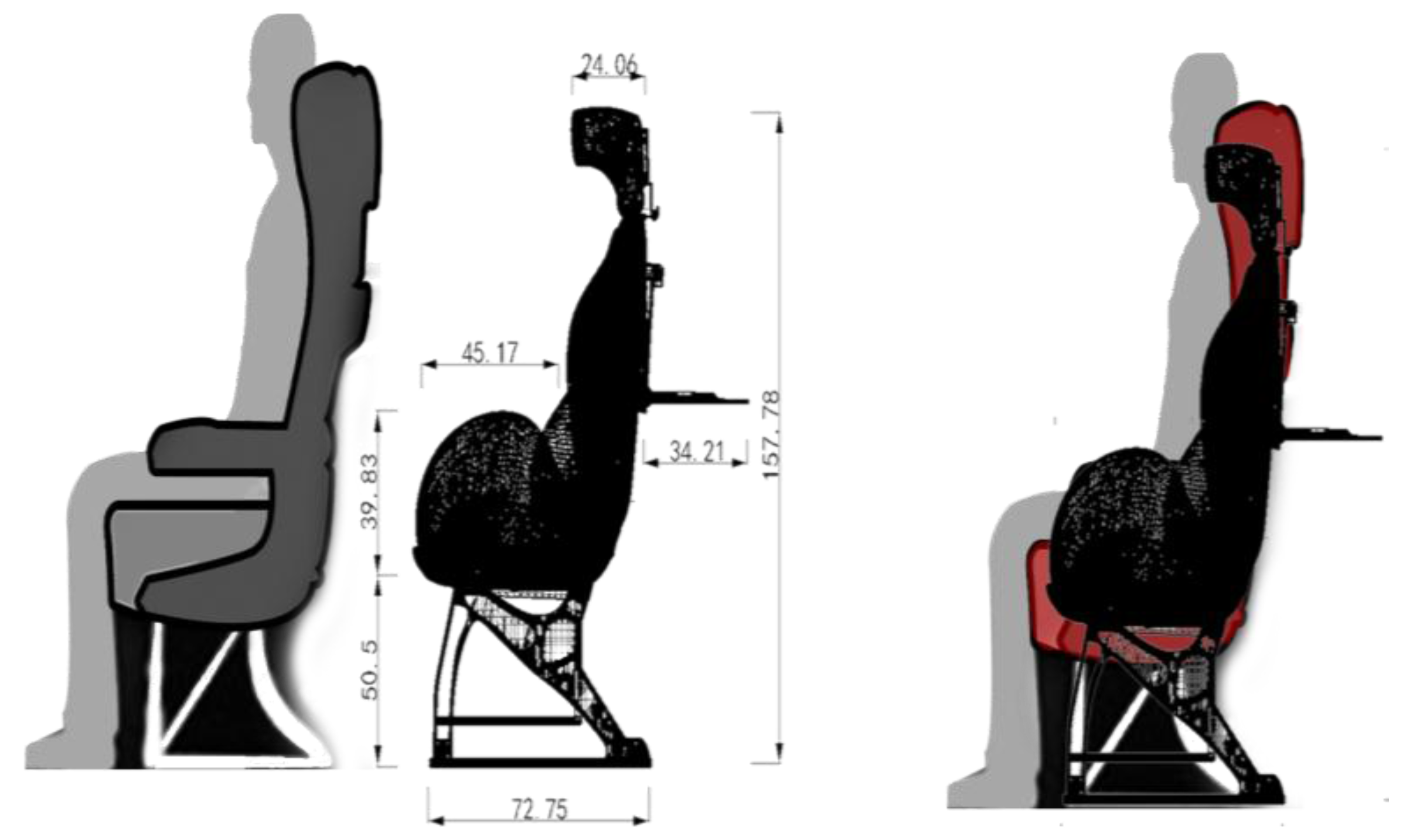
Figure 39.
Side dimension.
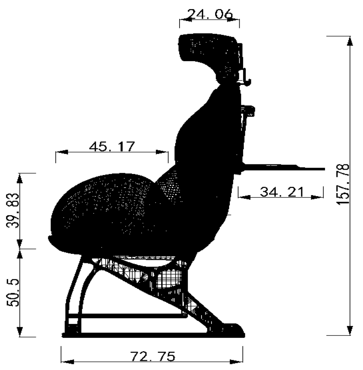
Figure 40.
Seat to seat dimension.

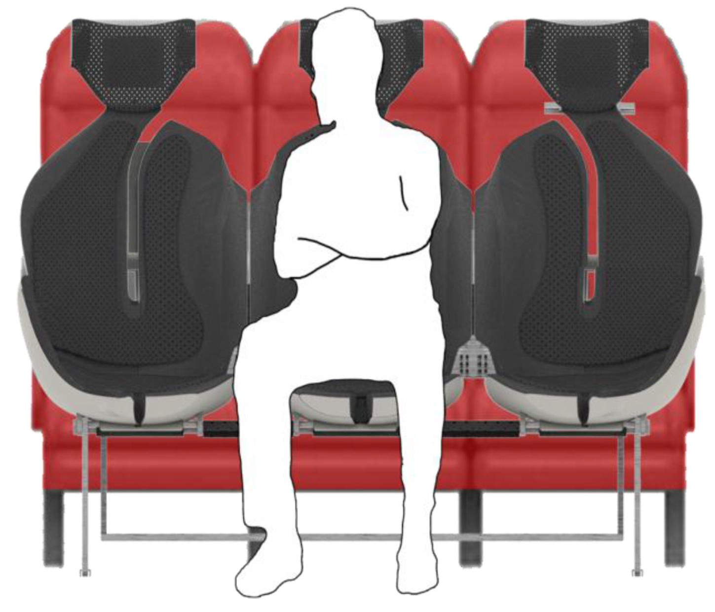
Figure 41.
Side view of final product.
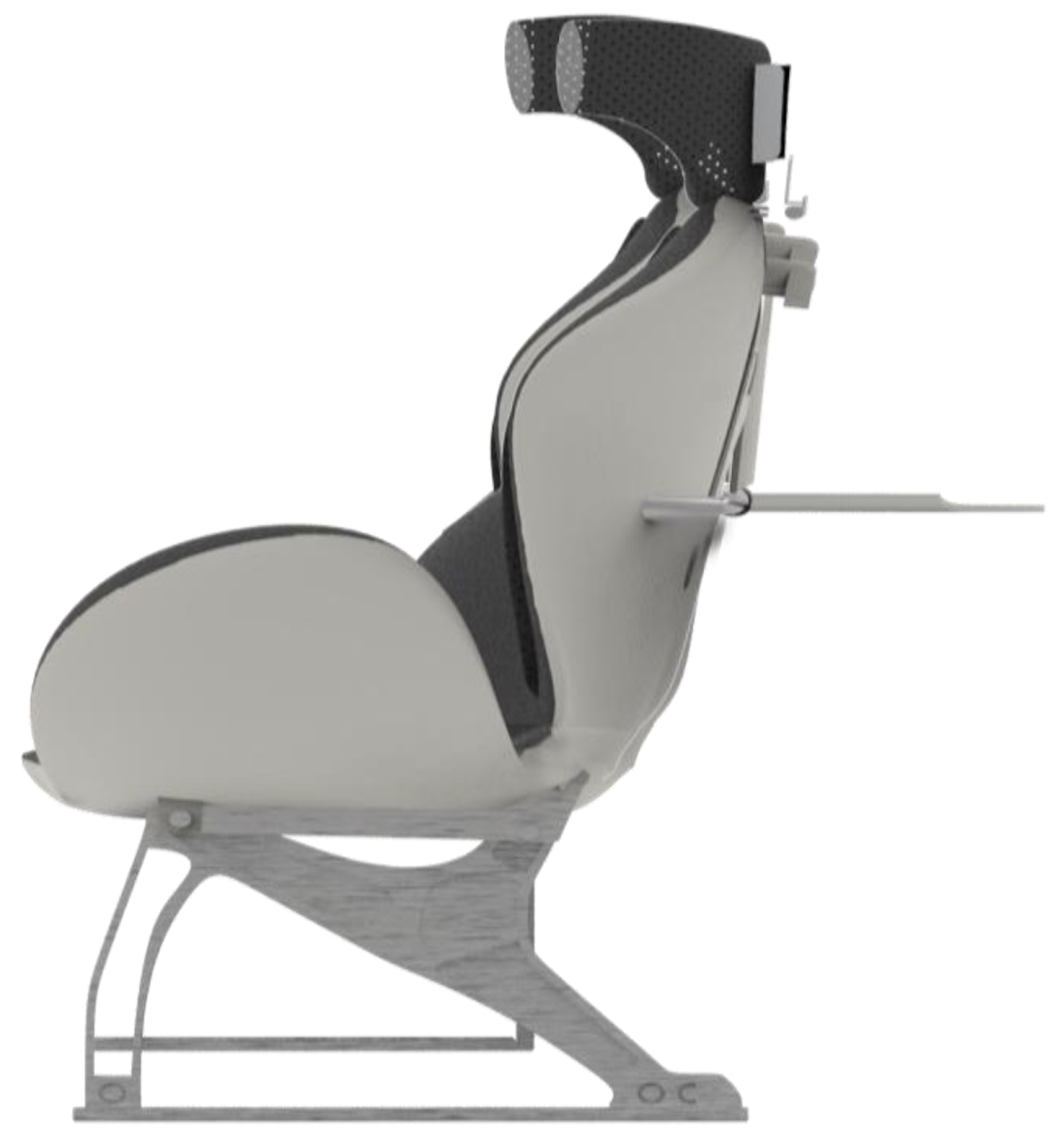
Figure 42.
Back view of final product.
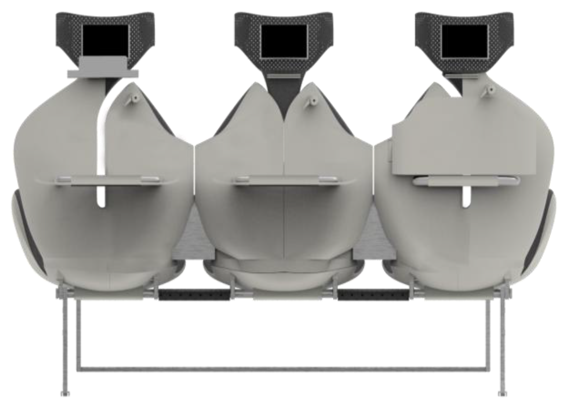
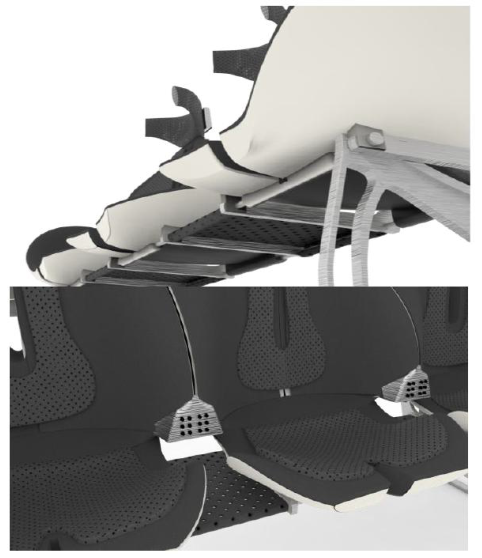
Figure 43.
Bottom view of final product.
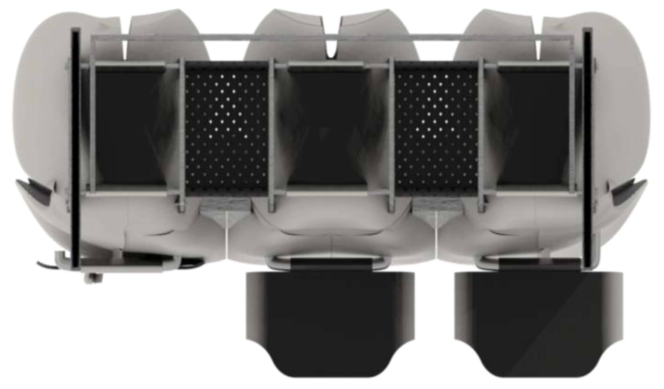
Figure 44.
Seat cushion of final product.

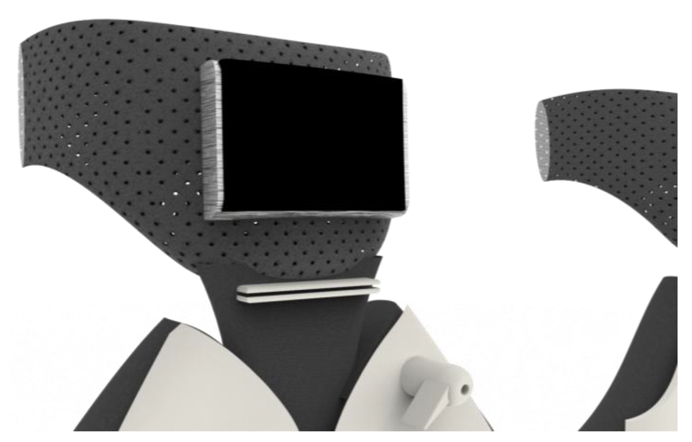
Figure 45.
IFE (in-flight entertainment).

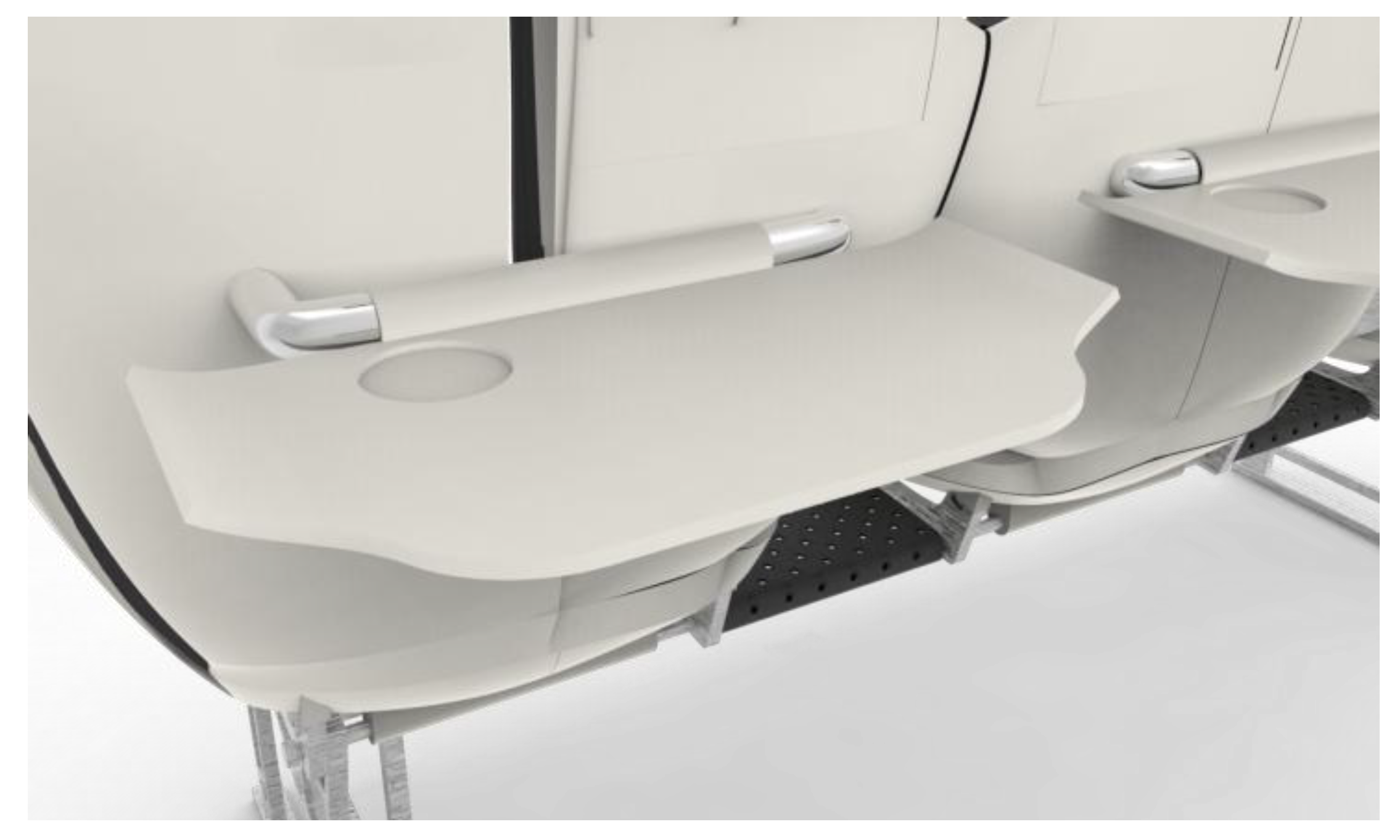
Figure 46.
Table top.

Table 1.
The pressure distribution on the backrest surface [7]. SD: Surface Distribution.
Table 1.
The pressure distribution on the backrest surface [7]. SD: Surface Distribution.
| Entry | No Lumbar Pillow | Small Lumbar Pillow | Middle Lumbar Pillow | Large Lumbar Pillow | ||||
|---|---|---|---|---|---|---|---|---|
| μ | SD (N = 6) | μ | SD (N = 6) | μ | SD (N = 6) | μ | SD (N = 6) | |
| Weight/kg | 13.95 | 8.7 | 15.7 | 9.41 | 16.53 | 8.74 | 17.00 | 9.59 |
| Surface/cm2 | 994.4 | 143.5 | 1180 | 154.9 | 1249.4 | 134.5 | 1246.9 | 135.6 |
| Pressure/kPa | 1.34 | 0.64 | 1.28 | 0.59 | 1.28 | 0.53 | 1.32 | 0.58 |
| Maximum/kPa | 3.28 | 1.04 | 3.33 | 1.04 | 3.28 | 0.81 | 3.56 | 1.18 |
| Slope/ | 0.26 | 0.05 | 0.30 | 0.06 | 0.28 | 0.04 | 0.29 | 0.05 |
| Maximum slope/ | 1.63 | 0.33 | 2.12 | 0.60 | 2.25 | 0.29 | 2.18 | 0.82 |
Table 2.
Correlativity between subjective and objective evaluation results [8].
Table 2.
Correlativity between subjective and objective evaluation results [8].
| Entry | Weight/kg | Surface/cm2 | Pressure/kPa | Maximum/kPa | Slope/ | Maximum Slope/ |
|---|---|---|---|---|---|---|
| Lumbar comfort | 0.679 | 0.661 | −0.227 | 0.196 | 0.022 | 0.613 |
| Back comfort | 0.982 | 0.971 | −0.514 | 0.536 | 0.58 | 0.934 |
| Shoulder comfort | 0.864 | 0.933 | 0.855 | 0.326 | 0.922 | 0.968 |
| Neck comfort | 0.776 | 0.868 | 0.91 | 0.219 | 0.948 | 0.923 |
| Total | 0.965 | 0.987 | −0.654 | 0.415 | 0.657 | 0.976 |
Table 3.
Optimal adjustable range [10].
Table 3.
Optimal adjustable range [10].
| Area | Male | Female | ||
|---|---|---|---|---|
| Lx/mm | θ/Degree | Lx/mm | θ/Degree | |
| Neck and shoulders | 670–770 | 10–20 | 570–620 | 10–15 |
| Upper limb | 570–670 | 5–20 | 570–620 | 0–15 |
| Truck | 620–720 | 10–20 | 570–620 | 10–20 |
| Lower limb | 670–770 | 5–20 | 620–670 | 5–20 |
| Operating gear | 620–670 | 0–10 | 570–620 | 0–15 |
© 2017 by the authors. Licensee MDPI, Basel, Switzerland. This article is an open access article distributed under the terms and conditions of the Creative Commons Attribution (CC BY) license (http://creativecommons.org/licenses/by/4.0/).
Share and Cite
MDPI and ACS Style
Cao, J.; Ku, D.; Du, J.; Ng, V.; Wang, Y.; Dong, W. A Structurally Enhanced, Ergonomically and Human–Computer Interaction Improved Intelligent Seat’s System. Designs 2017, 1, 11. https://doi.org/10.3390/designs1020011
AMA Style
Cao J, Ku D, Du J, Ng V, Wang Y, Dong W. A Structurally Enhanced, Ergonomically and Human–Computer Interaction Improved Intelligent Seat’s System. Designs. 2017; 1(2):11. https://doi.org/10.3390/designs1020011
Chicago/Turabian StyleCao, Jin, Da Ku, Jiachun Du, Vera Ng, Yufei Wang, and Weiqiao Dong. 2017. "A Structurally Enhanced, Ergonomically and Human–Computer Interaction Improved Intelligent Seat’s System" Designs 1, no. 2: 11. https://doi.org/10.3390/designs1020011