General Design Procedure for Free and Open-Source Hardware for Scientific Equipment


1
Department of Electrical and Computer Engineering, Michigan Technological University, Houghton, MI 49931, USA
2
Department of Electronics and Nanoengineering, School of Electrical Engineering, Aalto University, 02150 Espoo, Finland
3
Department of Materials Science and Engineering, Michigan Technological University, Houghton, MI 49931, USA
*
Author to whom correspondence should be addressed.
Designs 2018, 2(1), 2; https://doi.org/10.3390/designs2010002
Submission received: 4 December 2017
/
Revised: 20 December 2017
/
Accepted: 22 December 2017
/
Published: 30 December 2017
Abstract
:Distributed digital manufacturing of free and open-source scientific hardware (FOSH) used for scientific experiments has been shown to in general reduce the costs of scientific hardware by 90–99%. In part due to these cost savings, the manufacturing of scientific equipment is beginning to move away from a central paradigm of purchasing proprietary equipment to one in which scientists themselves download open-source designs, fabricate components with digital manufacturing technology, and then assemble the equipment themselves. This trend introduces a need for new formal design procedures that designers can follow when targeting this scientific audience. This study provides five steps in the procedure, encompassing six design principles for the development of free and open-source hardware for scientific applications. A case study is provided for an open-source slide dryer that can be easily fabricated for under $20, which is more than 300 times less than some commercial alternatives. The bespoke design is parametric and easily adjusted for many applications. By designing using open-source principles and the proposed procedures, the outcome will be customizable, under control of the researcher, less expensive than commercial options, more maintainable, and will have many applications that benefit the user since the design documentation is open and freely accessible.
Keywords:
RepRap; 3D printing; OpenSCAD; customization; open hardware; open science hardware; OScH; free and open-source hardware; FOSH; free and open-source software; custom designs; distributed manufacturing; P2P; P2P manufacturing; open design; scientific equipment; open scientific hardware; slide dryer
1. Introduction
The distributed digital manufacturing of free and open-source scientific hardware (FOSH) used for scientific experiments [1] has been shown to in general reduce the costs of scientific hardware by 90–99% [2]. These impressive cost savings have proven resilient across both standard [3] and custom equipment [4]. This has supported the rapid growth of an engineering subfield to develop FOSH for science, which is represented by the annual Gathering for Open Science Hardware [5] as well as two new academic journals, the Journal of Open Hardware and HardwareX. There are numerous examples of FOSH scientific equipment in all fields, ranging from syringe pumps [6] to self-assembling robots [7]. Examples exist in the field of biology [8,9,10,11,12], optics [13], and microfluidics [14,15]. Many open tools exist for physics and materials, including radial stretching systems with force sensors [16], a robot-assisted mass spectrometry assay platform [17], a large stage four-point probe [18], and automated microscopes [19]. Simple yet essential devices for health and medical treatment in the developing world include a mobile water quality tester [20] and a sample rotator mixer [21]. There are open-source ventures into Internet of things (IOT) energy monitors for buildings [22], energy-efficient homes and subsystems [23], and even smart cities [24]. With the development of building-block technologies, it is less time-consuming than it was in the past to share and collaborate on open-source scientific instruments [25].
One of the primary enabling innovations that provide the opportunity for distributed manufacturing of open-source hardware-based [26] scientific equipment is the 3D printing capabilities of the self-replicating rapid prototyper (RepRap) project [27]. RepRap 3D printers have been used to provide high-quality educational experiences for students in a wide range of disciplines in the classroom [28,29] and have become scientific platforms themselves [30]. A maturing network of peer-production [31] and 3D printing file repositories [32] provides both time and cost savings within scientific labs [33]. Combining 3D printing with off-the-shelf components and open-source electronics (e.g., the Arduino prototyping platform) has enabled the automation of scientific equipment. As the fabrication of scientific equipment moves away from a central paradigm of purchasing proprietary equipment to one in which scientists themselves download open-source designs, fabricate components with digital manufacturing technology, and then assemble the equipment themselves, there is a need for a standard procedure that designers can follow when targeting this audience. This procedure is made up of design steps, which are activities that have to be performed to come to a fully defined product [34,35], and follow a set of design principles, which are the general rules leading the cognitive activity of design in the appropriate direction [36].
This study provides such a generalized design procedure for the development of free and open-source hardware for scientific applications. After laying out and explaining each of the five steps in the procedure encompassing six design principles, a case study is provided for an open-source slide dryer. The case study is discussed as a practical example of the benefits and drawbacks of this approach.
2. Generalized Procedure
The generalized procedure contains five steps and encompasses six design principles:
- Evaluate existing similar scientific tools for their physical functions and base the design of the FOSH design off of replicating the physical effects, not pre-existing designs. If necessary, evaluate a proof of concept.
- Design, involving the following design principles:
- Use only free and open-source software tool chains and open hardware for the fabrication of the device.
- Attempt to minimize the number and type of parts and the complexity of the tool.
- Minimize the amount of material and the cost of production.
- Maximize the use of components that can be distributed digitally manufactured from using widespread and accessible tools such as the RepRap 3D printer.
- Create parametric designs with pre-designed components, which enable design customization.
- All components that are not easily and economically fabricated with existing open hardware equipment in a distributed fashion should be chosen from off-the-shelf parts, which are readily available throughout the world.
- Validate the design for the targeted function(s).
- Document the design, manufacture, assembly, calibration, and operation of the device meticulously. This should include the raw source of the design (e.g., computer aided design files (CAD)), not only the files used for production (e.g., stereolithography files (STL)).
- Share all of the documentation in the open-access literature.
3. Details of Each Procedure Step
3.1. Literature Review & Proof of Concept
A literature review must be undertaken before a new open hardware device is to be designed. This literature review should ensure that there have not been other open-source designs for the same device as well as detail how similar devices are fabricated for commercial applications. In both cases the fundamental concepts that are targeted are the physical steps that the device must perform as well as determining the metrics of success. Cooperation is important to thriving FOSH.
If a literature review reveals that a solution already exists, build off of what has been done, adding improvements or refinements.
In conjunction with this step, it may be useful to generate an as-simple-as-possible proof of concept. If there are even small signs of success, the design may be worth pursuing. However, if the proof of concept does not work, it may be wise to rethink the approach.
3.2. Design, Involving the Following Design Principles
3.2.1. Use of Only Free and Open-Source Tool Chain
Use free and open-source software design tools where possible in the initial design (e.g., open-source CAD packages such as OpenSCAD, FreeCAD, or Blender). For example, with an open-source customizer [37] it is possible for even novices to make customizable designs. FOSS should be used for all software whenever possible [38,39,40]. Finally, the fabrication equipment used to make the targeted device should run free and open-source firmware and should when possible be FOSH itself (e.g., a RepRap 3D printer). If that is not feasible, then low-cost and/or widely-used software packages and hardware should be favored. This is to ensure the widest possible accessibility of your designs for remixing by others.
Using FOSH and FOSS should fall in naturally with the scientific method as an important factor in the scientific method is repeatability. However, if an experiment uses high-priced proprietary tools, this is a barrier to others trying to replicate the results. By using open-source design methodologies for hardware, costs can be minimized, allowing for ease of replication and verification.
3.2.2. Minimize Complexity
In order to support maintenance, upgrading, repair, and end of life disassembly [41] and recycling [42], attempt to minimize the number and type of parts (e.g., use all the same type of fastener) and the complexity of the tool overall. Minimize dissimilar materials when unnecessary and reduce the part count. It should be noted, however, that the individual parts when digitally manufactured can be as complex as the tools (e.g., 3D printers) allow for, with no penalty.
Designers must consider that the users of their instruments may not be engineers or specifically skilled in instrument manufacturing. Therefore, complexity should also be reduced in manufacturing techniques as well as applied theories.
3.2.3. Minimize Material Consumption
By reducing the amount of material used, the environmental impact is minimized as the processing and transportation embodied energy are all reduced by the reduced use of material [43,44,45,46]. This can be done by eliminating non-functional bulk to designs, and, in 3D printed designs, minimizing infill percentage to fulfill mechanical requirements. In addition, material minimization reduces overall economic costs from reduced processing time as well as material costs.
3.2.4. Maximize Components that Can Be Digitally Manufactured and Distributed
The use of distributed digital manufacturing using widespread and accessible tools such as the RepRap 3D printer and open PCB mills [47] help to reduce both the environmental impact [43,44,45,46] as well as reduce the economic costs of production [48,49,50,51]. Lead times can also be reduced, as well as improving maintainability.
3.2.5. Create Parametric Designs
By making parametric designs rather than solving a specific case, all future cases can also be solved while enabling future users to alter the core variables to make the device useful for them. For example, a simple 3D printable syringe pump [6] resulted in thousands of downloads and customizations, creating millions of dollars of value for the scientific community in the first year of its release [50,51]. The syringe pumps were used in multi-material 3D printers [47], wax printing of paper-based microfluidics [15], and as a fluid handling robot for chemical and biological experiments [30]. In addition, the original design was improved and ported from a Raspberry Pi environment to an Arduino environment for in-lab control [52].
The creation of parametric tools allows a large degree of flexibility to the user. Properly parametrized 3D model designs will allow users to alter critical dimensions for their purposes. In some cases, it will also allow models to be reformatted such that they could be manufactured with a wide and unforeseeable range of tools.
3.2.6. Off-the-Shelf Parts
All customized parts are designed to be digitally manufactured, but often times less expensive components can be found that are mass manufactured (e.g., pipes, tubes, screws, etc.). These should be sourced so they are as widely available as possible throughout the world. Using off the shelf parts allow research labs to stock a minimum of parts, which are widely used. This, once again, reduces the lead time, which speeds up research.
3.3. Validation
In order for the FOSH tool to be used in the scientific community, it must be validated using a clear and transparent procedure and have a low-cost, effective method of calibration. Again, whenever possible, one should use other digitally manufactured open hardware tools and FOSS to complete the validation and calibration.
3.4. Proper Documentation
Documentation must actively assist a non-specialist with recreating the hardware. The Open Source Hardware Association (OSHWA) has extensive guidelines for properly documenting and releasing open-source designs [53]. In summary, the guidelines are:
- Share design files in the most universal type.
- Include a fully detailed bill of materials, including prices and sourcing information.
- If software is involved, make sure the code is clear and understandable to a layman.
- Include many photos such that nothing is obscured; these can be used as a reference while manufacturing.
- In the methods section, the entire manufacturing process must be detailed, as these are instructions for users to replicate the design.
- Share on many file hosting sites (see step 5 below), but also be sure to specify a license. This gives users information on what fair use of the design constitutes.
3.5. Share Aggressively
Open-source hardware can be at a disadvantage when competing with proprietary technology, because proprietary technology is sold through conventional channels and typically will have a marketing budget to pay for advertising. FOSH can be sold and marketed through this model as well, but in some cases this is not appropriate. In order for FOSH to proliferate, designs must be shared aggressively just to raise awareness of the existence of the option. All of the documentation for a project can be shared on the Open Science Framework, which is set up to take any type of file and handle large datasets. Software can be shared on sites like GitHub or SourceForge, and should include proper documentation on the inner workings of the code, as well as a brief summary. The 3D designs can be shared on sites set up by government scientific funders like the NIH 3D Print Exchange or open-source companies like Ultimaker’s YouMagine or MyMiniFactory as well as other repositories [54]. Circuit designs can be shared on sites like the Open Circuit Institute [55].
Designers should consider spreading designs to as many hosting sites as possible, as this will only increase exposure. Regardless of the site, it is important to engage with the community, building personal rapport. Building a reputation for intelligence, reliability, and helpfulness will bolster confidence in your designs and increase usage.
4. Case Study: Slide Dryer
This generalized procedure for design was developed through experience and relied heavily on the Open Source Lab [2] and the best practice guidelines from OSHWA [53]. In order to demonstrate the steps in the creation of FOSH hardware for science, a case study is presented on the development of an open-source slide dryer. Slide dryers are designed to gently warm glass microscope slides to decrease the drying time for experiments after cleaning steps. Slide dryers allow users to increase their productivity. Slide dryers are available commercially for $225–5245 [56]. Commercial slide dryers come in many different shapes and sizes, and with different capabilities [56]. As a generalization, all slide dryers provide a rack structure and a heat source.
In this case study the target is to design a FOSH slide dryer with an acceptable capacity (30 slides) and a fast drying rate (10 min or less). The numbers chosen are somewhat arbitrary but, due to the parametric design of the system, design constraints may be altered to better fit the requirements of a specific laboratory. Note that the two target features (capacity and dry time) cannot both be optimized using the current design—as drying time decreases, the slide count must also decrease for a given power consumption.
In the first step, the existing literature is surveyed for slide dryer designs. There have been some efforts to patent the concept of slide drying [57,58,59]. One attempt [57] uses an electric current to generate heat; however, it has since expired. Another design [58] patented in Russia uses forced air. Yet another design [59] uses gas forced through a tube in order to create heat and has also expired. Next, a search for open-source solutions is carried out. There is one design available on the Internet, “Glass Slide Dryer” [60]. Though this design is functional and less costly than commercial systems, it has a few apparent issues:
- Poor documentation and construction notes
- Not scalable
- Overly complex
- The performance of the device is not characterized.
These issues have prevented its widespread adoption.
Finally, commercialized slide dryers are reviewed. The most expensive option (over $5000) [56] is able to heat 57 slides (unless an additional shelf is purchased for $284) at 70 °C. Many other options are available [56,61,62,63,64,65], but all products are expensive considering their function. The cheapest design that almost fits the target specifications (its slide capacity is too small) comes in at $225 [56] and most slider dryers or warmers were $300–1000. A more detailed techno-economic comparison is made in Section 3.5.
Upon review of the existing options, it is found that the FOSH community is in need of a well-documented, customizable, and effective slide dryer. Concepts are generated, tested, and simplified and refined until an optimal design is found. The simple proof of concept (step 1) that led to this final design was simply aluminum wire wrapped around a box hooked to a variable power supply. The chosen design, which was designed to be parametric in OpenSCAD (steps 2a and 2e), involves 3D printing a base with a peg structure on an open-source 3D printer, (steps 2a and 2d). The 3D printable parts are designed to minimize filament consumption (step 2c). Then readily available wire (step 2f) can be woven across the base. When voltage is applied, electrical energy will be converted to heat due to the resistance of the wire [66] in a simple design (step 2b).
Twenty AWG copper magnet wire is selected for its low cost and resistance to corrosion [67]. The resistance is measured by measuring out a long length of wire, in this case 10 m. Then, using a fluke multimeter, the resistance of the length can be found. Simply by dividing the measured resistance by the length, the resistivity can be found. For the specific wire used [67], a resistivity of 0.000220 Ohm/mm is found. This value is required to find the minimum length of wire to match the selected power supply.
An off-the-shelf (step 2f) 12V 5A power supply is selected [68] due to both low cost and high availability. Additionally, most off-the-shelf supplies like the one selected have thermal overloads built in to prevent damage due to short circuits. Using Ohm’s law, the necessary length L can be found, given resistivity ρ, current I, and voltage V:
The wattage, P, consumed is simply defined by:
It should be noted that it is not wise to run a power supply continuously at full capacity [68]. Therefore, it is advised to use a fraction of the available I. In this case study, 90% of I is utilized in the design.
Once L has been determined, it is only a matter of distributing the wire among the rack system. The rack is developed in OpenSCAD (step 2a). This allows for the design to be entirely parametric (step 2e), as well as transferable to customizers [37]. Key parameters that the model depends on are:
- Wire Resistance: The measured resistivity of the heating element (in Ohm/mm).
- Wire Diameter: The diameter of the heating element (in mm).
- Supply V: The voltage of the power supply (in V).
- Supply I: Maximum allowable current from the power supply (in A).
- Slide count: The desired number of slides to dry (number).
- Slide Dimensions: Width and length of the slides (in mm)
- Printer Dimensions: The 3D print bed surface area X and Y size of the 3D printer to be used.
There are many lesser dimensional parameters, which specify features such as winding pegs and rack height, which can be adjusted by the user to make a slide dryer ideal for their application. The SCAD model will optimize the design to fit the user’s 3D printer, while minimizing part counts (step 2b). Each rack can be connected using snap-fit connectors also generated by the model. As this is a parametric design, it allows for similar results to be achieved via different means. For example, a smaller printer can be used by printing off a larger number of shelves to accommodate the same number of slides as a larger printer can do with fewer shelves but a greater area. If only a 24-V supply is available, simply by changing the parameters, the design can still facilitate the user’s desired number of slides. The intention of this design is not necessarily for users to replicate exactly what was used in this case study, but rather to empower them to use the materials and tools readily available in their lab or workplace to easily generate a useful and reliable slide dryer for themselves.
The example design based on the desired slide count generated seven shelves for a Lulzbot Taz 5 printer [69]. The design in the OpenSCAD environment can be viewed in Figure 1.
Following guidelines for appropriate documentation (step 4), the bill of materials along with item, number, price, and source are shown in Table 1. As can be seen in Table 1, the cost of the materials to build the open-source slider dryer for 30 slides is $16.63.
The manufacturing of the device is fairly simple. First, the user must print all necessary components. Then weave wire around the pegs (there should be one strand of wire per set of pegs). Once one shelf is completed, the user inserts the pegs, attaches the next shelf, and wraps the wire once around the peg to tension the lower shelf. This process is repeated for all shelves. Once complete, the user strips both ends of the wire with a razor blade and cuts and places 10-mm pieces of shrink tube over the wire (do not shrink them yet). Then the wire is soldered to the middle tab and the back tab of the barrel jack (the wire is not polarized, so it does not matter which wire is soldered to which tab). Finally, shrink the shrink tube over the solder joints, as well as the unconnected barrel jack tab (as in Figure 2).
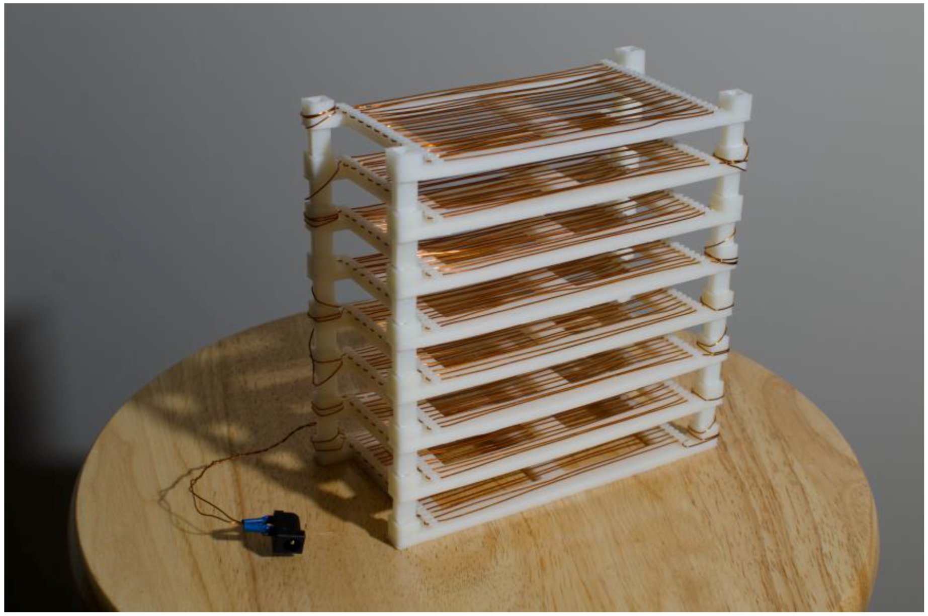
The slide dryer is sliced using open-source Cura Lulzbot Edition using the high-quality default print settings; 120 g of high impact polystyrene (HIPS) filament and 10.6 m of magnet wire is used. A 5.5 mm barrel jack is soldered to the wire ends in order to easily interface with the power supply. The assembled open-source slide dryer can be seen in Figure 3.
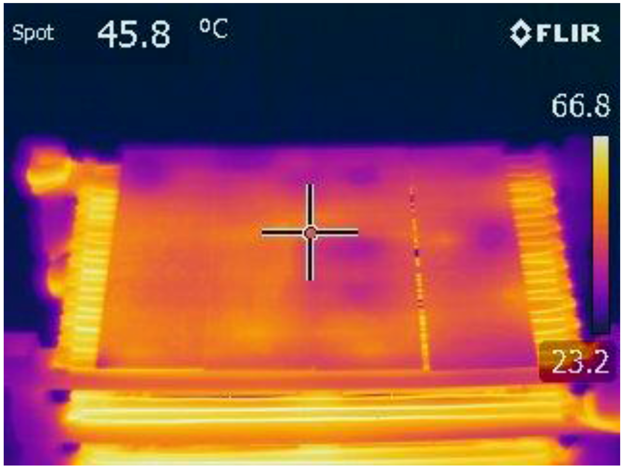
As validation (step 3), 30 slides are washed in water and rinsed in ethanol, and then placed on the open-source dryer. The dryer is then powered on, and the time-to-dry is measured while the temperature is being monitored with an open-source thermocouple-based data logger (T400, Pax Instruments). The warming kinetics experiment is repeated three times. A FLIR thermal distribution on a single rack is viewed with a thermal camera to demonstrate uniformity of heating. Lastly, dry time data for commercial solutions were collected via simulated devices using a heated plate and, in the case of the forced air variant, a fan. The plate is brought up to the maximum indicated temperature by the devices’ respective data sheet and then 10 trials are performed and averaged to find the drying times.
5. Results and Discussion
5.1. Drying Time and Temperature Uniformity
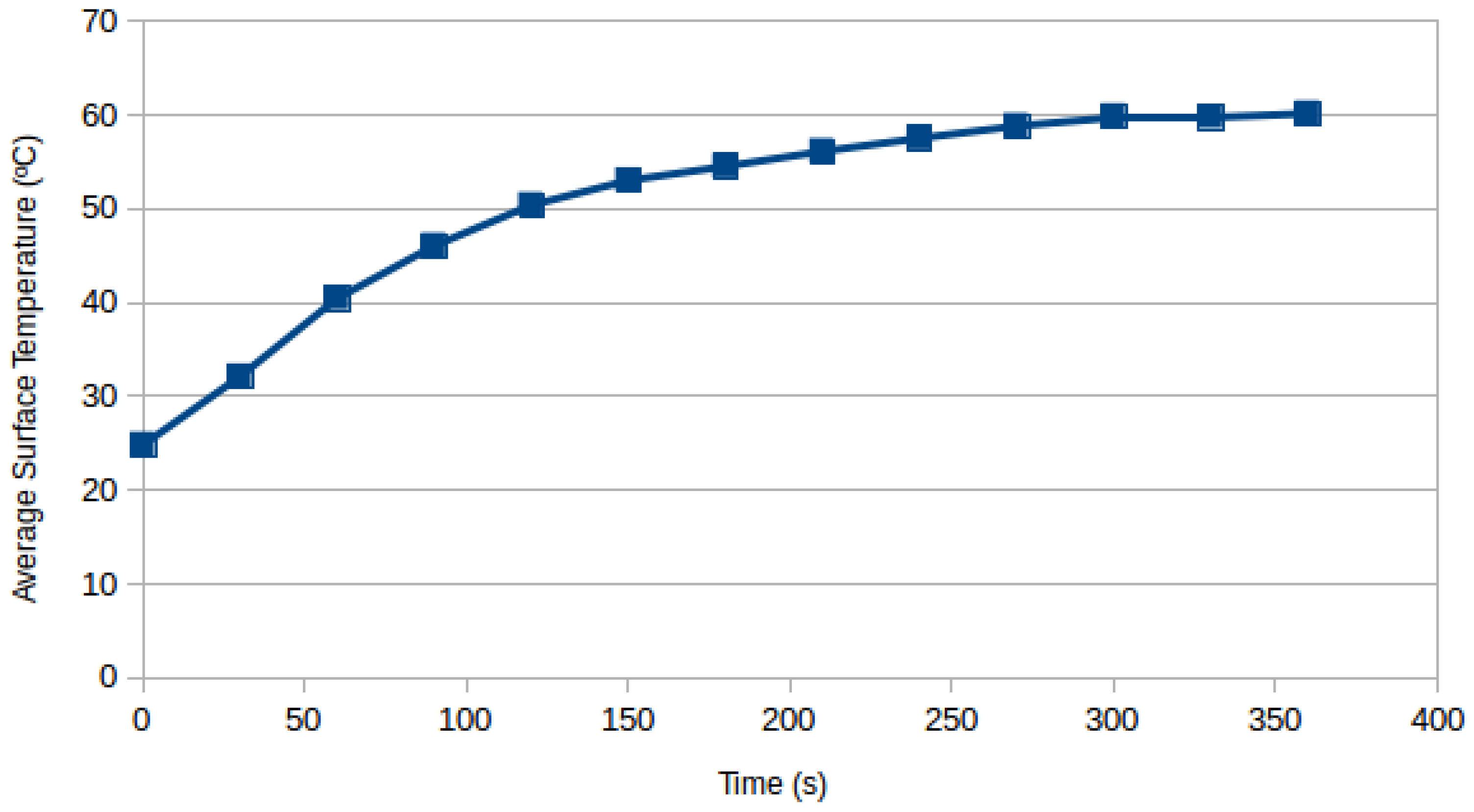
The open-source slide dryer successfully met the design parameters. The amount of time required to dry 30 slides is ~3 min (±1 min.), well below the desired 10-min target limit. The temperature during heat-up is recorded in Figure 4. On average it takes 5 min to fully heat up.
5.2. Customized Designs
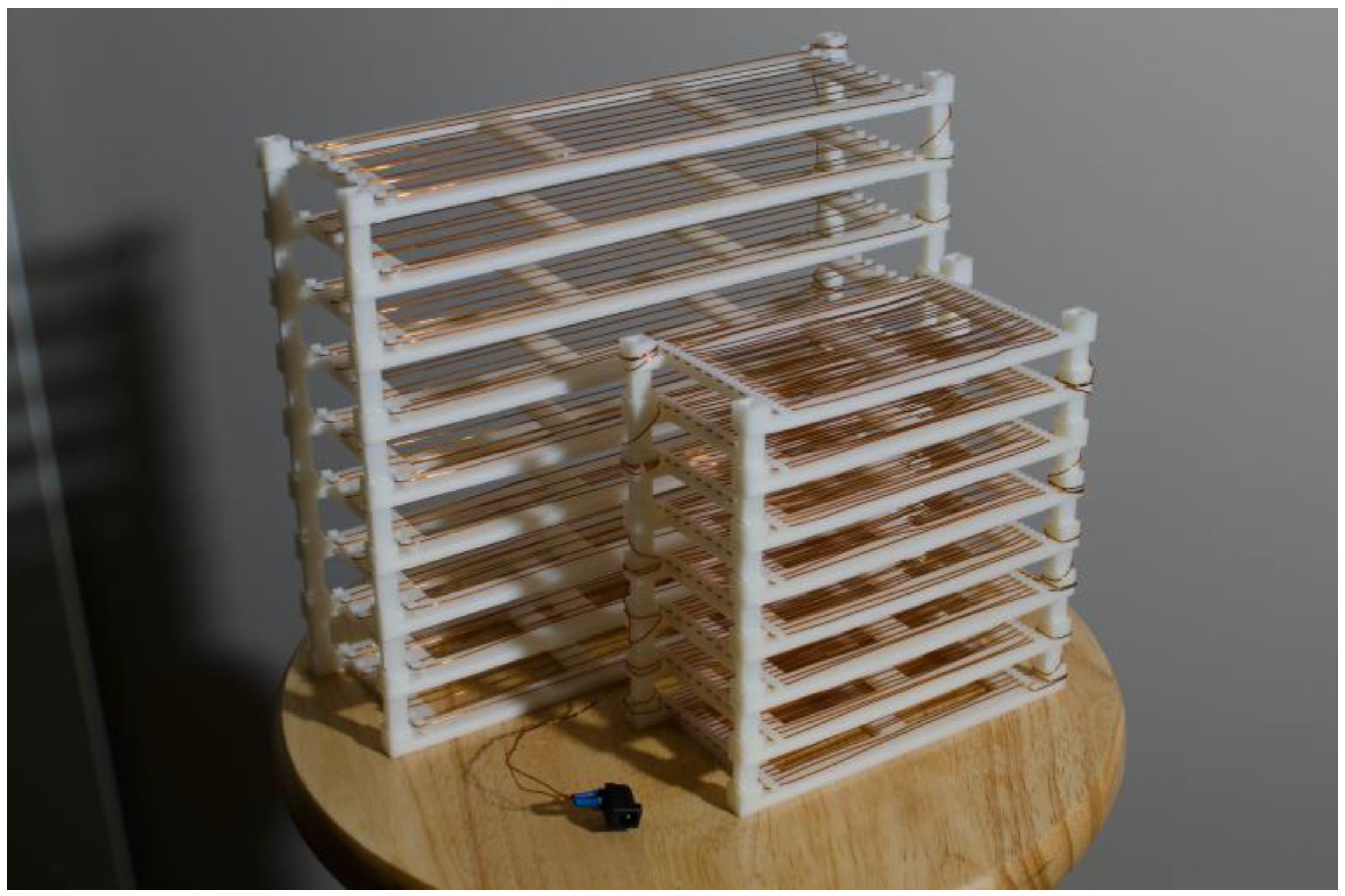
The parametric design of the open-source slide dryer allowed for different models to be generated and tested. For example, a slide dryer with a capacity of 66 slides was created using the same method as the 30-slide system (Figure 6). However, using the same power supply will yield insufficient heat to dry slides, and therefore will require a doubled voltage (24 V, 5 A supply) to have the same density. To have a significant increase in power, the design can remain as proposed for 66 slides, but instead use a 24 V 15 A supply to yield 240 watts of output.
5.3. Design Iterations
Many different design ideas were explored before arriving at the simple solution of applying a current directly to the wire. The first iteration was designed based off of a circuit suggested in [2], which involved an open-source microcontroller (Arduino) controlling a relay tied to high wattage resistors and a power supply. A thermistor was used as a control feedback, so the dryer could be set to a desired temperature. The resistors were put in a 3D printed enclosure with a fan and ventilation shafts. Slides were made to sit on top of the enclosure and have heat from the resistors transferred to them. The test design was prototyped using a breadboard. As this was clearly not a permanent solution, the electronics where put onto a custom circuit board and milled. Two designs were tested, one with utilizing the Arduino and relay, and the other utilizing an Op-Amp and MOSFET. The design ultimately was not selected due to a couple downfalls. First, the heat could not be transferred to the slides quickly enough. The resistors would hit peak heat, and the slides would take an excessive amount of time to dry (more than 30 min). The design was also overly complex. In addition, there were a couple unique parts to 3D print that were not simple-to-print geometry (as was the final design shown in Figure 1). Additionally, a custom circuit board, though convenient once made, is not approachable by all users. The final design is demonstrated to be superior because of its low unique part count (five parts total via step 2b), ease of manufacturing with minimal materials (step 2c) using open-source tools (step 2a), and highly parametric model (step 2e) using readily available off-the-shelf parts (step 2f). Another advantage over previously conceived designs is direct thermal contact, enabling more efficient energy use. The wire also distributes the heat, as proven in Figure 5, ensuring an even and quick dry, (as validated above, step 3). The complete design is open source and can be found at [70] (step 4). After publication of this article, the design will be shared aggressively on many 3D printing repositories (step 5) (NIH 3D Print Exchange, Youmagine, and MyMiniFactory, as well as in the PLOS Open Toolbox and Appropedia [71].
5.4. Safety
Efforts have been made to ensure safe and risk-free operation. Using magnet wire (a wire coated with a thin layer of insulation) allows for close thermal contact, but still protects from electrical short circuiting. If in any case the magnet wire gets scraped and bare copper is exposed, the wire must be replaced or, in some cases, it can be covered with liquid electrical tape. Covering insulation scrapes with additional insulation may cause a decrease in device performance, however. In case of a short circuit (metal placed between to exposed pieces of wire), the selected power supply will disable itself (via thermal overload) [68]. Finally, the solder tabs on the power connector are completely covered with shrink-tube for insulation.
5.5. Techno-Economic Comparisons
The price of the design is approximately $16.63, which is significantly less expensive than commercial alternatives (see direct comparisons in Table 2). Previous work has shown that the labor costs [3] of fabricating such open-source equipment are small and that moving to open-source scientific hardware is easily justified by economics alone. However, as the open-source slide dryer can be customized to fit the exact needs of the research group and the size can be accommodated by the design, the value to the researcher tends to be larger than simple economics would predict.
From the total costs and the cost per slide data available in Table 2, it is clear that the FOSH solution can be significantly more cost-effective than even the least expensive commercial solution. The advantage commercial slide driers have over the proposed FOSH solution is decreased drying time based on their maximum rated temperature. For the lowest cost per slide drying, the FOSH device is more than 7 times more cost-effective. In general, for a two orders of magnitude reduction in cost, the slide dry time is about doubled. Although the majority of the most cost-effective commercial solutions have rapid drying times, their capacity is less than half (almost a third) that of a solution like the FOSH 66 slide 24 V design. Effectively, this indicates that in large batches, the FOSH solution can outperform in terms of both cost and efficiency. In small batches, the FOSH design has a lower initial cost. The costs of proprietary slide dryers can come with other services (e.g., a warranty) that the user must determine are valuable enough to warrant paying the premium for commercial closed systems. Once again, the advantage the FOSH solution has over all closed-source commercial solutions is that it can be modified and optimized for a given researcher. If the drying times shown in this particular device are not sufficient for a lab’s needs, users may simply change the design parameters to increase the power output. If this is done to reach higher temperatures (e.g., 100 °C), then higher temperature thermopolymers are recommended for the 3D printed components. For example, polycarbonate (PC) is heat resistant up to 116 °C and would be appropriate to match any commercial slide dryer with a maximum temperature of 100 °C or below. PC costs about twice the HIPS used here, which would increase the cost of the FOSH device by about $5.00 for plastic in addition to the more powerful power supply. These changes do not alter the overall results of the economic analysis. Lastly, although many of the commercial versions were also open to the environment, a few were enclosed to stop contamination. The FOSH system could also be easily enclosed to reduce contamination.
5.6. Future Work
Future work can improve the slide dryer further by (1) building an enclosure to protect it from drafts and contaminants as well as dry the slides in an inert atmosphere; (2) change the geometry to dry different types of objects; (3) provide controls and temperature feedback for variable temperatures or for custom warming sequences to be followed; and (4) adjust the corners of the 3D printable design to enable better wire management. In addition, the open-source slide dryer design can be easily altered for many different applications far outside of the narrow scope focused on here. For example, this design could be altered into a parametric space heater, a part shelf, or a parametric load resistor. Submitting this design to popular 3D printing sites (step 5) will give the design exposure and could potentially spawn unconceivable permutations of the design.
In this case study, the slide dryer has become the property of the open-source community, and will empower researchers, teachers, and hobbyists alike to accelerate their own research when a slide dryer is appropriate. The cost of conventional scientific hardware is expensive because of a relatively low demand, making research-grade equipment prohibitively expensive [72]. By designing using open-source principles based on the proposed procedures, the outcome will be less expensive than commercial options, more maintainable, and will have many applications that benefit the user since the design documentation is open and free of proprietary information. As many scientists begin to use this design procedure in their own equipment, it will enable more rapid progress as we all have the opportunity to “stand on the shoulders of giants” [73].
6. Conclusions
This paper successfully demonstrated the use of a five-step procedure encompassing six design principles to develop open-source hardware designs for scientific equipment. In this case study the open-source slide dryer, which can be fabricated to have equivalent functionality for a small fraction of the cost of commercial systems, has become the property of the open-source community, and will empower researchers, teachers, citizen scientists, and hobbyists alike. The custom design is parametric and easily adjusted for many laboratories and other applications. By designing using open-source principles and the proposed procedures, the outcome will be customizable, under the control of the researcher, significantly more cost effective than commercial solutions, easy to maintain, and comes with fully free and open documentation.
Acknowledgments
This project was supported by the Michigan Tech Open Sustainability Technology Laboratory, Fulbright Finland, Aleph Objects, Pax Instruments, and ThermoAnalytics. The authors would also like to thank Yani Beeker and Logan Stetsko for the helpful discussions, as well as Adam Pringle, Bobbi Wood, and Mark Klien for technical assistance. The authors would also like to thank Sarah Oberloier for professional photography services and equipment and the anonymous reviewers for their helpful comments.
Author Contributions
Joshua M. Pearce conceived and designed the experiments; Shane Oberloier wrote the code, made the design, and performed the experiments; Shane Oberloier and Joshua M. Pearce wrote the paper.
Conflicts of Interest
The authors declare no conflict of interest.
References
- Pearce, J.M. Building Research Equipment with Free, Open-Source Hardware. Science 2012, 337, 1303–1304. [Google Scholar] [CrossRef] [PubMed]
- Pearce, J. Open-Source Lab: How to Build Your Own Hardware and Reduce Research Costs, 1st ed.; Elsevier: Waltham, MA, USA, 2014. [Google Scholar]
- Trivedi, D.K.; Pearce, J.M. Open Source 3-D Printed Nutating Mixer. Appl. Sci. 2017, 7, 942. [Google Scholar] [CrossRef]
- Liardon, J.L.; Barry, D.A. Adaptable Imaging Package for Remote Vehicles. HardwareX 2017, 2. [Google Scholar] [CrossRef]
- Dosemagen, S.; Liboiron, M.; Molloy, J. Gathering for Open Science Hardware. J. Open Hardw. 2016, 1, 4. [Google Scholar] [CrossRef]
- Wijnen, B.; Hunt, E.J.; Anzalone, G.C.; Pearce, J.M. Open-source syringe pump library. PLoS ONE 2014, 9, e107216. [Google Scholar] [CrossRef] [PubMed]
- Zykov, V.; Chan, A.; Lipson, H. Molecubes: An open-source modular robotics kit. In Proceedings of the IROS-2007 Self-Reconfigurable Robotics Workshop, San Diego, CA, USA, 2 November 2007. [Google Scholar]
- Baden, T.; Chagas, A.; Marzullo, T.; Prieto-Godino, L.; Euler, T. Open Laware: 3-D Printing Your Own Lab Equipment. PLoS Biol. 2015, 13, e1002086. [Google Scholar]
- Damase, T.R.; Stephens, D.; Spencer, A.; Allen, P.B. Open source and DIY hardware for DNA nanotechnology labs. J. Biol. Methods 2015, 2, e24. [Google Scholar] [CrossRef] [PubMed]
- Oh, J.; Hofer, R.; Fitch, W.T. An open source automatic feeder for animal experiments. HardwareX 2017, 1, 13–21. [Google Scholar] [CrossRef]
- McMunn, M.S. A time-sorting pitfall trap and temperature datalogger for the sampling of surface-active arthropods. HardwareX 2017, 1, 38–45. [Google Scholar] [CrossRef]
- Gali, H. An Open-Source Automated Peptide Synthesizer Based on Arduino and Python. Slas Technol. Trans. Life Sci. Innov. 2017, 22, 493–499. [Google Scholar] [CrossRef] [PubMed]
- Zhang, C.; Anzalone, N.C.; Faria, R.P.; Pearce, J.M. Open-source 3D-printable optics equipment. PLoS ONE 2013, 8, e59840. [Google Scholar] [CrossRef] [PubMed]
- Fobel, R.; Fobel, C.; Wheeler, A.R. DropBot: An open-source digital microfluidic control system with precise control of electrostatic driving force and instantaneous drop velocity measurement. Appl. Phys. Lett. 2013, 102, 193513. [Google Scholar] [CrossRef]
- Pearce, J.M.; Anzalone, N.C.; Heldt, C.L. Open-Source Wax RepRap 3-D Printer for Rapid Prototyping Paper-Based Microfluidics. J. Lab. Autom. 2016, 21, 510–516. [Google Scholar] [CrossRef] [PubMed]
- Schausberger, S.E.; Kaltseis, R.; Drack, M.; Cakmak, U.D.; Major, Z.; Bauer, S. Cost-Efficient Open Source Desktop Size Radial Stretching System With Force Sensor. IEEE Access 2015, 3, 556–561. [Google Scholar] [CrossRef]
- Chiu, S.H.; Urban, P.L. Robotics-assisted mass spectrometry assay platform enabled by open-source electronics. Biosens. Bioelectr. 2015, 64, 260–268. [Google Scholar] [CrossRef] [PubMed]
- Chandra, H.; Allen, S.W.; Oberloier, S.W.; Bihari, N.; Gwamuri, J.; Pearce, J.M. Open-source automated mapping four-point probe. Materials 2017, 10, 110. [Google Scholar] [CrossRef] [PubMed]
- Wijnen, B.; Petersen, E.E.; Hunt, E.J.; Pearce, J.M. Free and open-source automated 3-D microscope. J. Microsc. 2016, 264, 238–246. [Google Scholar] [CrossRef] [PubMed]
- Wijnen, B.; Anzalone, G.C.; Pearce, J.M. Open-source mobile water quality testing platform. J. Water Sanit. Hyg. Dev. 2014, 4, 532–537. [Google Scholar] [CrossRef]
- Dhankani, K.; Pearce, J.M. Open Source Laboratory Sample Rotator Mixer and Shaker. HardwareX 2017, 1, 1–12. [Google Scholar] [CrossRef]
- Pocero, L.; Amaxilatis, D.; Mylonas, G.; Chatzigiannakis, I. Open source IoT meter devices for smart and energy-efficient school buildings. HardwareX 2017, 1, 54–67. [Google Scholar] [CrossRef]
- Thomson, C.C.; Jakubowski, M. Toward an Open Source Civilization:(Innovations Case Narrative: Open Source Ecology). Innovations 2012, 7, 53–70. [Google Scholar] [CrossRef]
- Jiang, J.; Claudel, C. A high performance, low power computational platform for complex sensing operations in smart cities. HardwareX 2017, 1, 22–37. [Google Scholar] [CrossRef]
- Harnett, C. Open source hardware for instrumentation and measurement. IEEE Instrum. Meas. Mag. 2011, 14. [Google Scholar] [CrossRef]
- Gibb, A.; Abadie, S. Building Open Source Hardware: DIY Manufacturing for Hackers and Makers, 1st ed.; Addison-Wesley Professional: Boston, MA, USA, 2014. [Google Scholar]
- Sells, E.; Bailard, S.; Smith, Z.; Bowyer, A.; Olliver, V. RepRap: The Replicating Rapid Prototyper-Maximizing Customizability by Breeding the Means of Production. In Handbook of Research in Mass Customization and Personalization; World Scientific: Toh Tuck Link, Singapore, 2010; pp. 568–580. [Google Scholar]
- Kentzer, J.; Koch, B.; Thiim, M.; Jones, R.W.; Villumsen, E. An open source hardware-based mechatronics project: The replicating rapid 3-D printer. In Proceedings of the 4th International Conference on Mechatronics, Kuala Lumpur, Malaysia, 17–19 May 2011. [Google Scholar]
- Schelly, C.; Anzalone, G.; Wijnen, B.; Pearce, J.M. Open-source 3-D printing technologies for education: Bringing additive manufacturing to the classroom. J. Vis. Lang. Comput. 2015, 28, 226–237. [Google Scholar] [CrossRef]
- Zhang, C.; Wijnen, B.; Pearce, J.M. Open-source 3-D platform for low-cost scientific instrument ecosystem. J. Lab. Autom. 2016, 21, 517–525. [Google Scholar] [CrossRef] [PubMed]
- Moilanen, J.; Vaden, T. 3D Printing Community and Emerging Practices of Peer Production. First Monday 2013. [Google Scholar] [CrossRef]
- Coakley, M.F.; Hurt, D.E.; Weber, N.; Mtingwa, M.; Fincher, E.C.; Alekseyev, V.; Chen, D.T.; Yun, A.; Gizaw, M.; Swan, J.; et al. The NIH 3D print exchange: A public resource for bioscientific and biomedical 3D prints. 3D Print. Addit. Manuf. 2014, 1, 137–140. [Google Scholar] [CrossRef] [PubMed]
- Coakley, M.; Hurt, D.E. 3D Printing in the Laboratory: Maximize Time and Funds with Customized and Open-Source Labware. J. Lab. Autom. 2016, 21, 489–495. [Google Scholar] [CrossRef] [PubMed]
- Bonvoisin, J.; Galla, J.K.; Prendeville, S. Design Principles for Do-It-Yourself Production. In International Conference on Sustainable Design and Manufacturing; Springer: Bolongna, Italy, 2017; pp. 77–86. [Google Scholar]
- Fu, K.K.; Yang, M.C.; Wood, K.L. Design principles: Literature review, analysis, and future directions. J. Mech. Des. 2016, 138, 101103. [Google Scholar] [CrossRef]
- Pahl, G.; Beitz, W. Engineering Design; Springer: London, UK, 2016. [Google Scholar]
- Nilsiam, Y.; Pearce, J.M. Free and Open Source 3-D Model Customizer for Websites to Democratize Design with OpenSCAD. Designs 2017, 1, 5. [Google Scholar] [CrossRef]
- Feller, J.; Fitzgerald, B. Understanding Open Source Software Development London; Addison-Wesley: London, UK, 2002; pp. 143–159. [Google Scholar]
- Lakhani, K.R.; Wolf, R.G. Why hackers do what they do: Understanding motivation and effort in free/open source software projects. Perspect. Free Open Source Softw. 2005, 1, 3–22. [Google Scholar] [CrossRef]
- Hippel, E.V.; Krogh, G.V. Open source software and the “private-collective” innovation model: Issues for organization science. Organ. Sci. 2003, 14, 209–223. [Google Scholar] [CrossRef]
- Harjula, T.; Rapoza, B.; Knight, W.A.; Boothroyd, G. Design for disassembly and the environment. CIRP Ann. Manuf. Technol. 1996, 45, 109–114. [Google Scholar] [CrossRef]
- Zhong, S.; Pearce, J.M. Tightening the loop on the circular economy: Coupled distributed recycling and manufacturing with recyclebot and RepRap 3-D printing. Resour. Conserv. Recycl. 2018, 128, 48–58. [Google Scholar] [CrossRef]
- Kreiger, M.; Pearce, J.M. Environmental life cycle analysis of distributed three-dimensional printing and conventional manufacturing of polymer products. ACS Sustain. Chem. Eng. 2013, 1, 1511–1519. [Google Scholar] [CrossRef]
- Kreiger, M.A.; Mulder, M.L.; Glover, A.G.; Pearce, J.M. Life cycle analysis of distributed recycling of post-consumer high density polyethylene for 3-D printing filament. J. Clean. Prod. 2014, 70, 90–96. [Google Scholar] [CrossRef]
- Gebler, M.; Uiterkamp, A.J.S.; Visser, C. A global sustainability perspective on 3D printing technologies. Energy Policy 2014, 74, 158–167. [Google Scholar] [CrossRef]
- Faludi, J.; Bayley, C.; Bhogal, S.; Iribarne, M. Comparing environmental impacts of additive manufacturing vs traditional machining via life-cycle assessment. Rapid Prototyp. J. 2015, 21, 14–33. [Google Scholar] [CrossRef]
- Anzalone, G.C.; Wijnen, B.; Pearce, J.M. Multi-material additive and subtractive prosumer digital fabrication with a free and open-source convertible delta RepRap 3-D printer. Rapid Prototyp. J. 2015, 21, 506–519. [Google Scholar] [CrossRef]
- Petersen, E.E.; Pearce, J. Emergence of Home Manufacturing in the Developed World: Return on Investment for Open-Source 3-D Printers. Technologies 2017, 5, 7. [Google Scholar] [CrossRef]
- Petersen, E.E.; Kidd, R.W.; Pearce, J.M. Impact of DIY Home Manufacturing with 3D Printing on the Toy and Game Market. Technologies 2017, 5, 45. [Google Scholar] [CrossRef]
- Pearce, J. Quantifying the Value of Open Source Hardware Development. Mod. Econ. 2015, 6, 1–11. [Google Scholar] [CrossRef]
- Pearce, J.M. Return on investment for open source scientific hardware development. Sci. Public Policy 2015, 43, 192–195. [Google Scholar] [CrossRef]
- Lynch Open Source Syringe Pump Modifications. Available online: http://www.appropedia.org/Lynch_open_source_syringe_pump_modifications (accessed on 29 November 2017).
- Best Practices for Open-Source Hardware 1.0. Available online: https://www.oshwa.org/sharing-best-practices/ (accessed on 29 November 2017).
- Printable Part Sources. Available online: http://reprap.org/wiki/Printable_part_sources (accessed on 29 November 2017).
- Open Circuit Institute. Available online: http://opencircuitinstitute.org/ (accessed on 29 November 2017).
- Slide Warmers and Oven/Incubators. Available online: https://www.emsdiasum.com/microscopy/products/histology/heaters.aspx (accessed on 29 November 2017).
- Microscopic-Slide Drier. Available online: https://patents.google.com/patent/US1170739A (accessed on 29 November 2017).
- Шахтная аэрожёлобная сушилка. Available online: https://patents.google.com/patent/RU2589894C1 (accessed on 29 November 2017).
- Slide Staining and Heating Rack. Available online: https://patents.google.com/patent/US2101161A (accessed on 29 November 2017).
- Glass Slide Dryer. Available online: https://3dprint.nih.gov/discover/3dpx-004001 (accessed on 29 November 2017).
- VWR Slide Warmers Dryers. Available online: https://us.vwr.com/store/product/3617131/slide-warmers-dryers (accessed on 29 November 2017).
- Fischer Scientific Slide Warmers. Available online: https://www.fishersci.com/us/en/products/I9C8KUA7/slide-warmers.html (accessed on 29 November 2017).
- Thomas Scientific Slide Warmers. Available online: https://www.thomassci.com/search/go?ThomasDomain=www.thomassci.com&w=slide+warmers (accessed on 29 November 2017).
- Lab Scientific Slide Warmers. Available online: https://labscientific.com/Cytology/Tissue-Floating-Bath-and-Slides-Warmer/Slide-Warmers/ (accessed on 29 November 2017).
- Agar Scientific Slide Warmers. Available online: http://www.agarscientific.com/slide-warmers-for-24-slides-and-56-slides.html (accessed on 29 November 2017).
- Irwin, J.D.; Nelms, D.I. Basic Engineering Circuit Analysis, 10th ed.; Wiley: Hoboken, NJ, USA, 2011; p. 27. ISBN 978-0-470-63322-9. [Google Scholar]
- Remington Industries. 20H200P 20 AWG Magnet Wire, Enameled Copper Wire, 200 Degree, 1.0 lb., 0.0343″ Diameter, 314′ Length, Natural. Available online: http://a.co/gbuYXLf (accessed on 29 November 2017).
- LEDMO Power Supply, Transformers, LED Adapter, 12V, 5A Max, 60 Watt Max, for LED Strip. Available online: http://a.co/2FwKrqr (accessed on 29 November 2017).
- LulzBot TAZ 5. Available online: https://www.lulzbot.com/store/printers/lulzbot-taz-5 (accessed on 29 November 2017).
- Open Source Slide Dryer. OSF. Available online: https://osf.io/rm2ah/ (accessed on 4 December 2017).
- Appropedia. Available online: http://www.appropedia.org/ (accessed on 2 December 2017).
- Pearce, J.M. Impacts of Open Source Hardware in Science and Engineering. Bridge 2017, 47, 24–31. [Google Scholar]
- Dryden, M.D.; Fobel, R.; Fobel, C.; Wheeler, A.R. Upon the Shoulders of Giants: Open-Source Hardware and Software in Analytical Chemistry. Anal. Chem. 2017, 89, 4330–4338. [Google Scholar] [CrossRef] [PubMed]
Figure 1.
A rendering of the slide dryer in OpenSCAD.
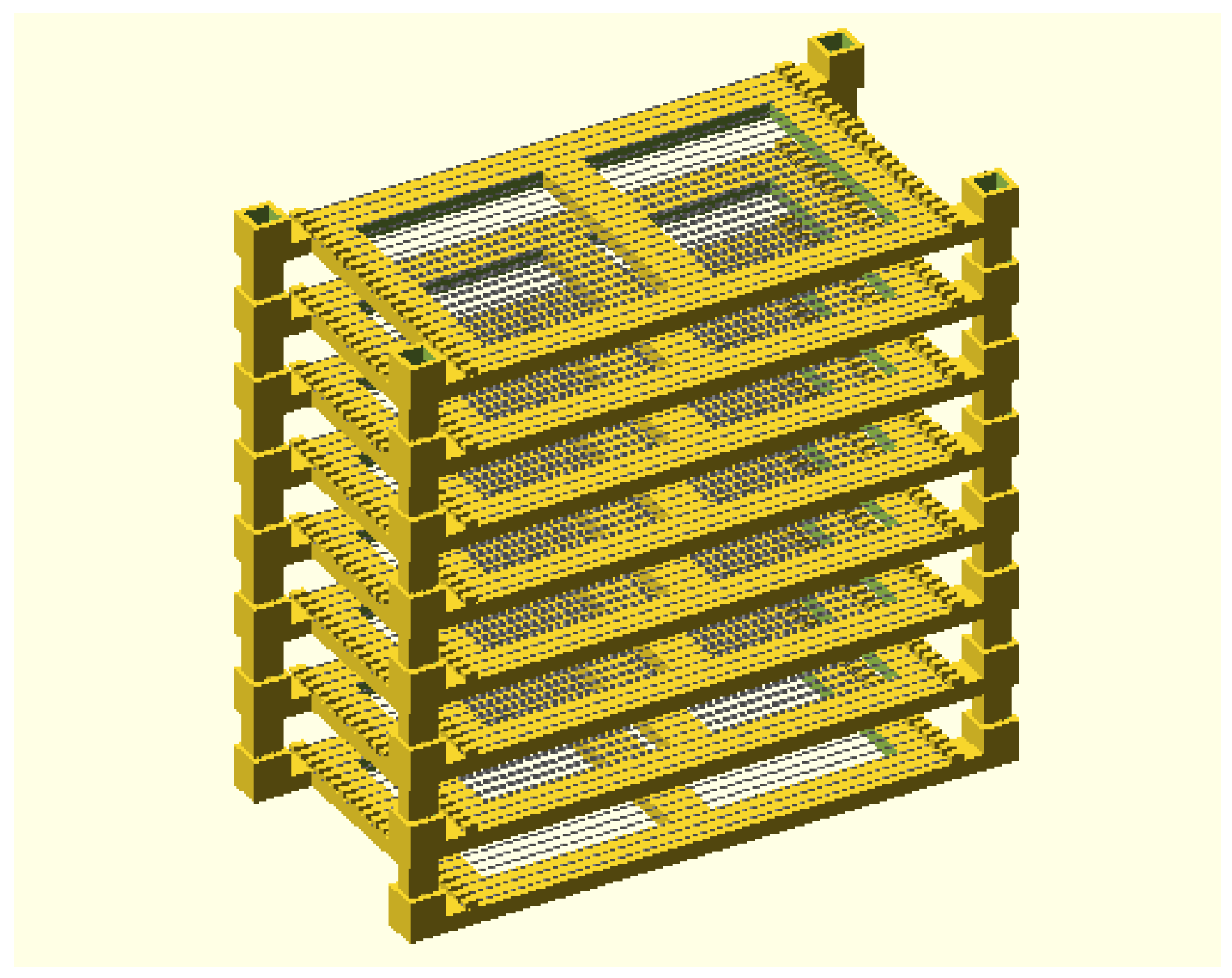
Figure 2.
Barrel jack connections and covering.
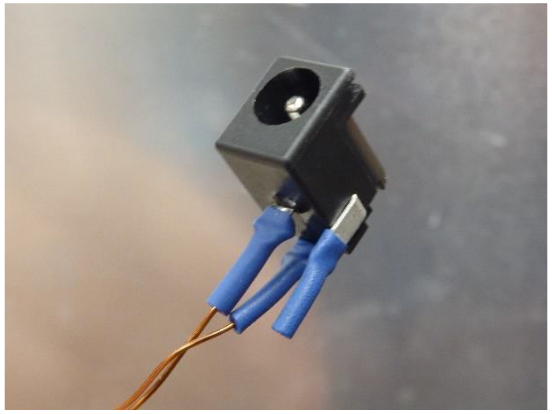
Figure 3.
The completed 30-slide open-source dryer.

Figure 4.
Average surface temperature of slides as a function of time for the open-source slide dryer (30-slide version).
Figure 4.
Average surface temperature of slides as a function of time for the open-source slide dryer (30-slide version).

Figure 5.
The thermal distribution of the wet slides while drying.

Figure 6.
Comparing design options for the open-source slide dryer: 66-slide dryer behind a 30-slide dryer.
Figure 6.
Comparing design options for the open-source slide dryer: 66-slide dryer behind a 30-slide dryer.


Table 1.
Bill of materials for the 30 slide—open-source slide dryer.
| Part | Link | Quantity | Cost |
|---|---|---|---|
| HIPS Filament | https://www.lulzbot.com/store/filament/hips | 120 g | $4.79 |
| 20 AWG Magnet wire | http://a.co/gbuYXLf | 10.6 m | $2.16 |
| 12 V 5 A Power Supply | http://a.co/7YzVkHB | 1 | $8.89 |
| Barrel Jack | https://www.digikey.com/short/q7wbrm | 1 | $0.76 |
| Shrink Tube | https://www.digikey.com/short/q300mc | 30 mm | $0.03 |
Table 2.
A comparison of commercial slide driers and the FOSH solution. Times denoted with * indicate experiment-based predictions based on maximum device temperature and not actual measurements from the device.
Table 2.
A comparison of commercial slide driers and the FOSH solution. Times denoted with * indicate experiment-based predictions based on maximum device temperature and not actual measurements from the device.
| Name | Cost (US$) | Capacity | US$/Slide | Max Temp. | Drying Time |
|---|---|---|---|---|---|
| FOSH 30 slide drier | 16.63 | 30 slides | 0.55 | 58 | 3.21 min |
| FOSH 66 slide drier | 23.82 | 66 slides | 0.36 | 42 | 4.58 min |
| FOSH 66 Slide drier (24 V) | 41.12 | 66 slides | 0.62 | 66 | 2.16 min |
| SHUR/Dry Slide Dryer III [56] | 5245.00 | 38 slides | 138.03 | 70 | 1.00 min * |
| Large Size Economical Slide Warmer [56] | 1274.00 | 66 slides | 19.30 | 100 | 1.37 min * |
| Slide Drying Bench, Electrothermal [61] | 1131.21 | 50 slides | 22.62 | 100 | 1.37 min * |
| Scientific Device Slide Heater [62] | 1080.00 | 20 slides | 54.00 | 65 | 1.66 min * |
| Slide Warmer [63] | 301.00 | 23 slides | 13.09 | 70 | 1.63 min * |
| XH-2002 [64] | 350.00 | 23 slides | 15.22 | 75 | 1.31 min * |
| Slide Warmers for 24 slides [65] | 317.00 | 24 slides | 13.22 | 70 | 1.63 min * |
| Slide warmer 23 slides [56] | 225.00 | 23 slides | 9.78 | 70 | 1.63 min * |
| Slide warmer 66 slides [56] | 285.00 | 66 slides | 4.32 | 70 | 1.63 min * |
© 2017 by the authors. Licensee MDPI, Basel, Switzerland. This article is an open access article distributed under the terms and conditions of the Creative Commons Attribution (CC BY) license (http://creativecommons.org/licenses/by/4.0/).
Share and Cite
MDPI and ACS Style
Oberloier, S.; Pearce, J.M. General Design Procedure for Free and Open-Source Hardware for Scientific Equipment. Designs 2018, 2, 2. https://doi.org/10.3390/designs2010002
AMA Style
Oberloier S, Pearce JM. General Design Procedure for Free and Open-Source Hardware for Scientific Equipment. Designs. 2018; 2(1):2. https://doi.org/10.3390/designs2010002
Chicago/Turabian StyleOberloier, Shane, and Joshua M. Pearce. 2018. "General Design Procedure for Free and Open-Source Hardware for Scientific Equipment" Designs 2, no. 1: 2. https://doi.org/10.3390/designs2010002