Next Article in Journal
Reply to Giannakos, K. Comment on: Toughness of Railroad Concrete Crossties with Holes and Web Openings. Infrastructures 2017, 2, 3
Previous Article in Journal
Quantifying the Financial Impact of Climate Change on Australian Local Government Roads
 
 
Reply published on 13 April 2017, see Infrastructures 2017, 2(2), 5.
Comment

Comment on: Toughness of Railroad Concrete Crossties with Holes and Web Openings. Infrastructures 2017, 2, 3

by
Konstantinos Giannakos
Civil Engineer, PhD, Fellow ASCE, Member TRB AR050 & 060 Committees, fib, AREMA, 108 Neoreion Str., Piraeus 18534, Greece
Infrastructures 2017, 2(1), 4; https://doi.org/10.3390/infrastructures2010004
Submission received: 10 January 2017 / Revised: 11 January 2017 / Accepted: 9 February 2017 / Published: 21 February 2017
The present brief comment is regarding the technical note “Toughness of railroad concrete crossties with holes and web opening”, by Erosha K. Gamage, Sakdirat Kaewunruen, Alex M. Remennikov, and Tetsuya Ishida [1].
I judge from my experience (please see some of my relevant publications [2,3,4,5,6,7,8,9,10,11,12,13,14,15,16,17,18] about loading and dimensioning of concrete sleepers; uploaded in http://giannakoskonstantinos.com/wp) that their technical note is of little value since it does not include dynamic testing of the sleepers/crossties, but it is based only on static tests. I briefly describe the research performed with me as the coordinator, for a period of over twenty years.
The investigation of railway matters in Greece had been undertaken during the development of the Greek Railways’ network and the design, construction, and maintenance of new and upgraded (high-speed) lines planned for operational speeds of up to 250 km/h (155 m/h) and axle-loadmax = 22.5 t; this development has been co-financed by European Union/EU and the Greek Government, since the 1980s, and it is performed according to the EU’s regulations and technical specifications. This decision (of increasing the permissible maximum operational speed in the network) resulted in a huge research program, in order to adapt the entire railway system to the needs of the High-Speed networks. The research program—extending over twenty years in total, in collaboration with universities in Greece (National Technical University of Athens/NTUA, Professor Th.P. Tassios; Aristotle University of Thessaloniki, Professor Tsotsos) and abroad (Graz University, Professor K. Riessberger; Munich Technical University, Professor G. Leykauff, etc.) and with research teams from research institutes: Institute of Geological and Mineral Research/IGME, initials of the relevant Greek words, Center of Research of Public Works, of the Ministry of Public Works/KEDE, initials of the relevant Greek words, in Greece and European State railway networks (French/SNCF and Sofrerail, Belgian/SNCB-Transurb Consult, German/DB, etc.)—led to the development of highly respected know-how and new fields of scientific knowledge. One of the main problems observed—before the research program—was the cracking of the concrete sleepers and the implied deterioration of the geometry of the track. Of the U2/U3 Vagneux type twin-block concrete sleepers (produced in Greece with the license and responsibility of the French company which produced them for the SNCF) laid on track, 60% or more exhibited cracks in the Greek network, at a position under the rail, propagating upwards from the lower seating surface of the sleeper on the ballast. It is noted that the same sleeper type in the French Railway network (maximum operational speed 200 km/h, daily tonnage 50,000 t) did not exhibit any problems at all. In Greece—at that time—the maximum operational speed was 140 km/h, daily tonnage 10,000 t, and Co-Co diesel locomotives were used of approximately 21 t/axle static load.
The existing international literature includes various methods that propose different formulas for a realistic estimation of actions on sleepers. The most commonly utilized (semi-analytic) formulas are found in the German, French, and American literature (cited in detail in e.g., [6,7,16]). The values of actions calculated through these formulas, assuming the most adverse conditions, justify the sporadic appearance of cracks (on the order of 1%–2%), but in no case their systematic appearance in over 60% of the sleepers (approaching even 80% in some parts) laid in tracks under operation, as it was observed in the Greek railway network (at the 1980s). The following Figure 1 depicts the results of the four methods cited in the German, French, and American literature, and the Giannakos method for: rail-type UIC60, doubly-elastic (in both directions: upwards and downwards) fastening RN with its elastic pad of 4.5 mm, twin-block concrete sleeper U3/U2 type, ballast two year old on track (polluted ballast bed and stiff support ρballast = 380 kN/mm), and a sensitivity analysis for the fluctuation of the subgrade’s static stiffness coefficient ρsubgrade = csubgrade from 40 (for pebbly substructure) to the most adverse conditions of 250 kN/mm (for stiff (rigid) subgrade at the bottom of a tunnel or on a concrete bridge with an insufficient thickness of ballast-bed), where ρ is the symbol of the static stiffness coefficient of each layer in the French and Greek literature, and c is the symbol in the German literature, both in kN/mm. RN is the fastening-type (for the attachment/fixation of the rail-foot on the sleeper’s upper surface) applied on U2/U3 twin-block (on monoblock also) sleepers in the French railway network. Pad’s Load-Deflection curve is cited in Fiche/Code of UIC/IUR 864-5/01-01-86 “Specification technique pour la fourniture de semelles a poser sous rails”, 4e edition; U.I.C.= initials for the “Union Internationale des Chemins de Fer”/“International Union of Railways”.
The results from Figure 1 led to a more exhaustive investigation of the extensive appearance of cracks on sleepers, which would lead to the development of a new methodology (Giannakos 2004 method) for the calculation of the actions on sleepers, which would be able to simulate and explain the phenomena that were observed in the Greek network (see [2,3,4,5,6,7,8,9,10,11,12,13,14,15,16,17,18,19,20]). One factor with a decisive influence on the value of the dynamic component of the actions is the value of the Non-Suspended (Unsprung) Masses/NSM of the vehicles and their behavior due to the dip of the (vertical) displacement of the track, the static stiffness coefficient of the track, the condition of the rail running table, etc. Two more parameters, that highly influence the value of the dynamic component of the actions, are the static and the dynamic stiffness coefficients of the pads of the fastenings; the static stiffness coefficient can be derived -each time- from the Load-Deflection curve of each pad and it is mathematically related to the dynamic stiffness coefficient.
After the research program, a mathematical approach to forecast the behavior of the Non-Suspended (Unsprung) Masses, for the estimation of actions was presented and compared with the real conditions on the track and the results of laboratory tests. The life-cycle of the sleepers and the track is highly affected by the loading. The results are useful for the design and every-day maintenance of the railway lines.
During this research program, testing of the strength of the concrete sleepers was performed: static tests in NTUA (Profs. Th.P. Tassios and K. Trezos [21]) and dynamic tests (see [7,22,23,24,25]) in the French State Railways/SNCF, at the laboratory of the “Research Department Voie/Track”, at Saint-Ouen/Paris, for two consecutive years [22,23,24,25].
The laboratory static-loading tests provided results for the sleeper’s strength; 500 kN/50 t for the U2/U3 type (Vagneux) twin-block sleeper and 750 kN/75 t for the U31 type (Vagneux) twin-block sleeper [22]; these are the failure thresholds. Dynamic tests in Saint Ouen’s laboratory provided strength results (failure threshold); 260 kN/20 t for U31 (operational load 200 kN/20 t) and 140–175 kN/14–17.5 t for U2/U3 [23,24,25]. This means that the failure threshold of the dynamic test is approximately 33% of the static test! According to the French State Railways’/SNCF’s regulations and technical specifications of that time for the U2/U3-type sleepers, the sleeper service load was 125–130 kN and the design load was 140–175 kN, consequently the sleeper failure (nominal) load was between 140 and 175 kN (see Appendix A below and Figure 1, where only the limits of the dynamic tests are used, as failure -and the cracking also- threshold; the static tests are not mentioned/used at all). The French State Railways’/SNCF’s specifications, for the strength of sleepers, did not take into account the static tests at all! (see [6,19,20,26]). A thorough description of the Giannakos (2004) method for the loading and the strength of concrete sleepers is also described in [20,27], textbooks for Railway Engineering of the Civil Engineering Department of the University of Thessaly (2007–2014). Furthermore, fib/International Federation of Concrete has adopted this method (Giannakos 2004) for precast concrete railway track systems (sleepers included; [28]). An article was also presented and included in TRB’s 2013 proceedings [29] for the Ultimate Strength/Failure Threshold vs. Actions on Track for the Ties’ Design in High-Speed and Heavy Haul Railroads.
Consequently, it is misleading to use static and not dynamic tests, as the authors (Erosha K. Gamage, Sakdirat Kaewunruen, Alex M. Remennikov, and Tetsuya Ishida) did in their technical note; they should also measure the sleeper’s strength under the dynamic load-test. The same principle has been included in Paragraph 4.2.3. of EN13230-2, which should also be applied. Apparently, this field of know-how is shared inside a very restricted cycle of scientists; the researchers should perform a complete and thorough research.
It is obvious that experience and know-how (theoretical and in practice)—based on results—in railway engineering depends on a lot of parameters, and not simply by the teaching experience gained in universities only, without any contact with the real operating conditions in railway networks.

Conflicts of Interest

The author of the present comment declares no conflict of interest.

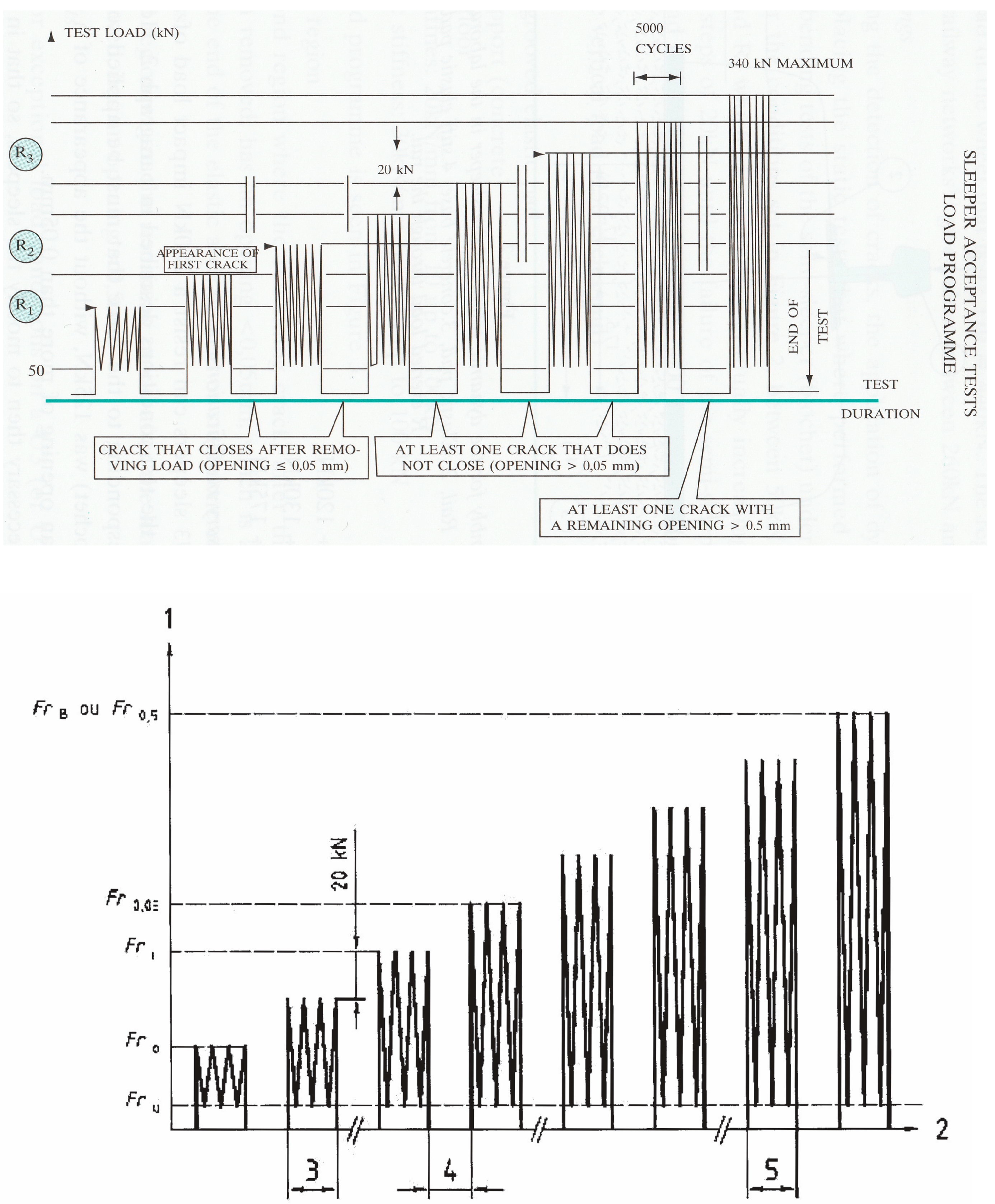
Appendix A. Tests for Concrete Sleepers—Acceptance Criteria (Excerpt of [6])

Figure A1 illustrates the dynamic test—according to the 1989 and 2003 regulations of the French State Railways (SNCF)—for the determination of the bearing capacity of a concrete sleeper (in kN). Since the sleepers U2 and U3 were produced in 1972–1978 and the research program was conducted in 1988 and 1989, the laboratory tests were performed according to the French standards (Norme Francaise 1989) and the SNCF standards (SNCF 1980) of that time. The dynamic testing of the sleepers was designed to correspond to three load regions as depicted in Figure A1 (upper illustration).
The lower illustration of Figure A1 shows the test procedure for the acceptance of concrete sleepers as described in the modern European Norms (EN 13230-2, 2003) and it is quite similar to the French Norms of 1989. The three load regions defined in the French regulations are determined by tests conducted under adverse seating conditions and are described below:
Figure A1. Dynamic test for the determination of the bearing capacity in kN of a concrete sleeper. (upper illustration) Program of Loading, at the sleeper’s rail seat section, of the dynamic test for the acceptance of the sleepers (Giannakos, 2004) according to Norme Francaise 1989 (see [27]). (Lower illustration) Dynamic test procedure, at the sleeper’s rail seat section, for the acceptance of the sleepers (EN 13230-2, 2003), where (1) load, (2) time, (3) 5000 load cycles, (4) maximum examination time of 5 min (5) frequency between 2 and 5 Hz.
Infrastructures 02 00004 g002
1st region or region R1 (Pre-cracking stage): Appearance of the first dim cracks, that disappear after unloading: this region is, in general, of little importance, because it varies greatly according to the tensile strength of the concrete (reinforcement does not undertake any stresses at this point). The strength of the sleeper itself is only slightly affected by these cracks. This load region reaches 100 kN (~10 t) with a maximum of 110 or 120 kN, and corresponds to adverse seating conditions of the sleeper (Figure A1 upper illustration, R1 level).
2nd region or R2 region (Post-cracking Service Load stage): Noticeable cracks appear, whose opening remains ≤0.05–0.1 mm after unloading. These cracks do not obstruct the track operation (that is, despite the cracks, the support conditions of the rail (on the ballast-bed) are ensured). During laboratory tests, the aforementioned cracking must appear in: 125 kN ≤ R2 ≤ 130 kN for the U2/U3 sleeper (Figure A1 upper illustration, R2 level).
3rd region or R3 region (Post-serviceability Cracking stage): The cracks remain open after unloading with opening ≥0.5 mm. This stage precedes and practically characterizes the complete failure of the sleeper (Figure A1 upper illustration, R3 level). During laboratory tests, the aforementioned cracking must be located between 140 kN and 175 kN for the U2/U3 sleeper.
During their operation in a track under circulation, the sleepers that meet these requirements will be able to resist the following loads:
In region R1: normal operational load. This includes the static load and the low frequency component of the dynamic load (in this case, every semi-sleeper undertakes: half of the static load of the axle plus an additional load due to superelevation/cant deficiency or excess plus an additional (dynamic) load due to the Suspended—and the Sprung—Masses of the vehicles).
In region R2: exceptional cases of dynamic loads, which are frequently observed on the track. These overloads are generated—mainly—from the Non-Suspended (Unsprung) Masses (NSM), from the ordinary defects of the rail running table, such as bad welds, wheel burns, etc., and from the ordinary defects of the wheels. These loads refer to loads that are beyond the normal operation (service) loads of the “wheel-rail-sleeper-ballast-substructure” system.
In region R3: exceptional cases of overloads, which are not frequently observed, such as: forgotten fastening clips on the rail running table, rail ruptures, gaps on the rail running table due to a shelling of a rail head section, wheel flats that exceed the acceptable tolerances, etc.

References and Notes

  1. Gamage, E.K.; Kaewunruen, S.; Remennikov, A.M.; Ishida, T. Toughness of railroad concrete crossties with holes and web openings. Infrastructures 2017, 2, 3. [Google Scholar] [CrossRef]
  2. Giannakos, K.; Loizos, A. Ballast stressing on a railway track and the behavior of limestone ballast. In Advances in Transportation Geotechnics; CRC Press and Taylor & Francis Group: Boca Raton, FL, USA, 2008; pp. 577–584. [Google Scholar]
  3. Giannakos, K.; Tsoukantas, S. Design methodology of slab track systems. In Advances in Transportation Geotechnics; CRC Press and Taylor & Francis Group: Boca Raton, FL, USA, 2008; pp. 585–592. [Google Scholar]
  4. Giannakos, K.; Loizos, A. Actions on railway track panel and ballast—Behavior of the Hellenic limestone ballast. In Bearing Capacity of Roads, Railways and Airfields; Taylor & Francis Group: Boca Raton, FL, USA, 2009; pp. 1263–1272. [Google Scholar]
  5. Giannakos, K. Theoretical calculation of the track-mass in the motion of unsprung masses in relation to track dynamic stiffness and damping. Int. J. Pavement Eng. 2010, 11, 319–330. [Google Scholar] [CrossRef]
  6. Giannakos, K.; Loizos, A. Evaluation of actions on concrete sleepers as design loads–Influence of fastenings. Int. J. Pavement Eng. 2010, 11, 197–213. [Google Scholar] [CrossRef]
  7. Giannakos, K. Loads on track, ballast fouling and life-cycle under dynamic loading in railways. J. Transp. Eng. 2010, 136, 1075–1084. [Google Scholar] [CrossRef]
  8. Giannakos, K. Reduced service life of concrete sleepers due to inadequate design. In Concrete under Severe Conditions; Taylor & Francis Group: Boca Raton, FL, USA, 2010; pp. 1281–1288. [Google Scholar]
  9. Giannakos, K. Comparison of magnitude of actions on track in high-speed and heavy-haul railroads—Influence of fastenings. Transp. Res. Rec. 2012, 2289, 70–77. [Google Scholar] [CrossRef]
  10. Giannakos, K. Influence of the Track’s Damping on the Track-Mass that Participates in the Motion of the Non-Suspended Masses of the Railway Vehicles; Volume in Honour of the professor George A. Giannopoulos; Aristotle University of Thessaloniki: Thessaloniki, Greece, 2012; pp. 81–94. (In Greek) [Google Scholar]
  11. Giannakos, K. Track defects and the dynamic loads due to non-suspended masses of railway vehicles. Int. J. Mech. 2013, 7, 180–191. [Google Scholar]
  12. Giannakos, K. Actions on a railway track, due to an isolated defect. Int. J. Control Autom. 2014, 7, 195–212. [Google Scholar] [CrossRef]
  13. Giannakos, K. Design loads on railway substructure: Sensitivity analysis of the influence of the fastening stiffness. Int. J. Railw. 2014, 7, 46–56. [Google Scholar] [CrossRef]
  14. Giannakos, K. Influence of a bent or battered joint or welding on the dynamic loads due to the non-suspended masses of railway vehicles. Int. J. Mech. 2014, 8, 307–318. [Google Scholar]
  15. Giannakos, K. Mathematical analysis of the transient loads for a deformed joint or welding in a railway Track. Int. J. Eng. Math. Model. 2015, 2, 51–62. [Google Scholar]
  16. Giannakos, K. Deflection of a railway reinforced concrete slab track: Comparing the theoretical results with experimental measurements. Eng. Struct. J. 2016, 122, 296–309. [Google Scholar] [CrossRef]
  17. Giannakos, K. Modeling the influence of short wavelength defects in a railway track on the dynamic behavior of the non-suspended masses. J. Mech. Syst. Signal Process. 2016, 68–69, 68–83. [Google Scholar] [CrossRef]
  18. Giannakos, K. Second order differential equation of motion in railways: The variance of the dynamic component of actions due to the sprung masses of the vehicles. Int. J. Theor. Appl. Mech. 2016, 1, 30–37. [Google Scholar]
  19. Prud’homme, A.; Erieau, J. Les Nouvelles Traverses en Beton de la SNCF; RGCF 2/1976; Revue Generale des Chemins de Fer/RGCF: Paris, France, 1976. [Google Scholar]
  20. Giannakos, K. Selected Topics in Railway Engineering, revised 4th version; Department of Civil Engineering, University of Thessaly: Volos, France, 2012; Chapter 14. [Google Scholar]
  21. Tasios, T.P.; Trezos, K. Laboratory Tests and Measurements on OSE Sleepers; National Technical University of Athens (NTUA)/Reinforced Concrete Laboratory, Research Program: Athens, Greece, 1989. [Google Scholar]
  22. OSE(Greek Railway Organization)/SNCF, Cooperation: 3/1989. Programme d’ essais realize au centre d’ essais de la Direction de l’ Equipement, OSE’s archives. 1989.
  23. OSE/SNCF, Cooperation: 6/1988. Comportment des traverses en relation avec les charges dynamiques, OSE’s archives. 1988.
  24. Giannakos, K.; Iordanidis, P.; Vlassopoulou, I. OSE Committee of Experts Report on their visit to SNCF from 15.5.1988/11.6.1988; OSE/Track Directorate: Athens, Greece, 1988. [Google Scholar]
  25. Giannakos, K.; Iordanidis, P.; Vlassopoulou, I. Summary Report of the Committee for the Issue of Twin-Block Sleepers after the Second Visit to SNCF in March 1989; OSE/Track Directorate: Athens, Greece, 1989. [Google Scholar]
  26. SNCF—Direction de l’ Equipement. Specification Technique VRE 2321 80-06 (B), Pour la Fourniture de traveRses Mixtes en Beton Arme, June 1980.
  27. Giannakos, K. Actions on the Railway Track; Papazissis Publicatios: Athens, Greece, 2004. [Google Scholar]
  28. fib/Federation Internationale du beton/International Federation of Concrete. Precast Concrete Railway Track Systems, with the participation of Giannakos, K., as railway expert. 2006.
  29. Giannakos, K. Ties’ design in high-speed and heavy haul railroads: Ultimum strength vs. actions on track. In Proceedings of the TRB Annual Meeting, Washington, DC, USA, 13–17 January 2013.
Figure 1. The results of the four methods (American, German, French, and Giannakos) for the loading and the strength of the U3/U2 concrete sleeper with RN fastenings, after a sensitivity analysis for the fluctuation of ρsubgrade [15].
Infrastructures 02 00004 g001

