
Materials and Life Science Experimental Facility at the Japan Proton Accelerator Research Complex IV: The Muon Facility


Abstract
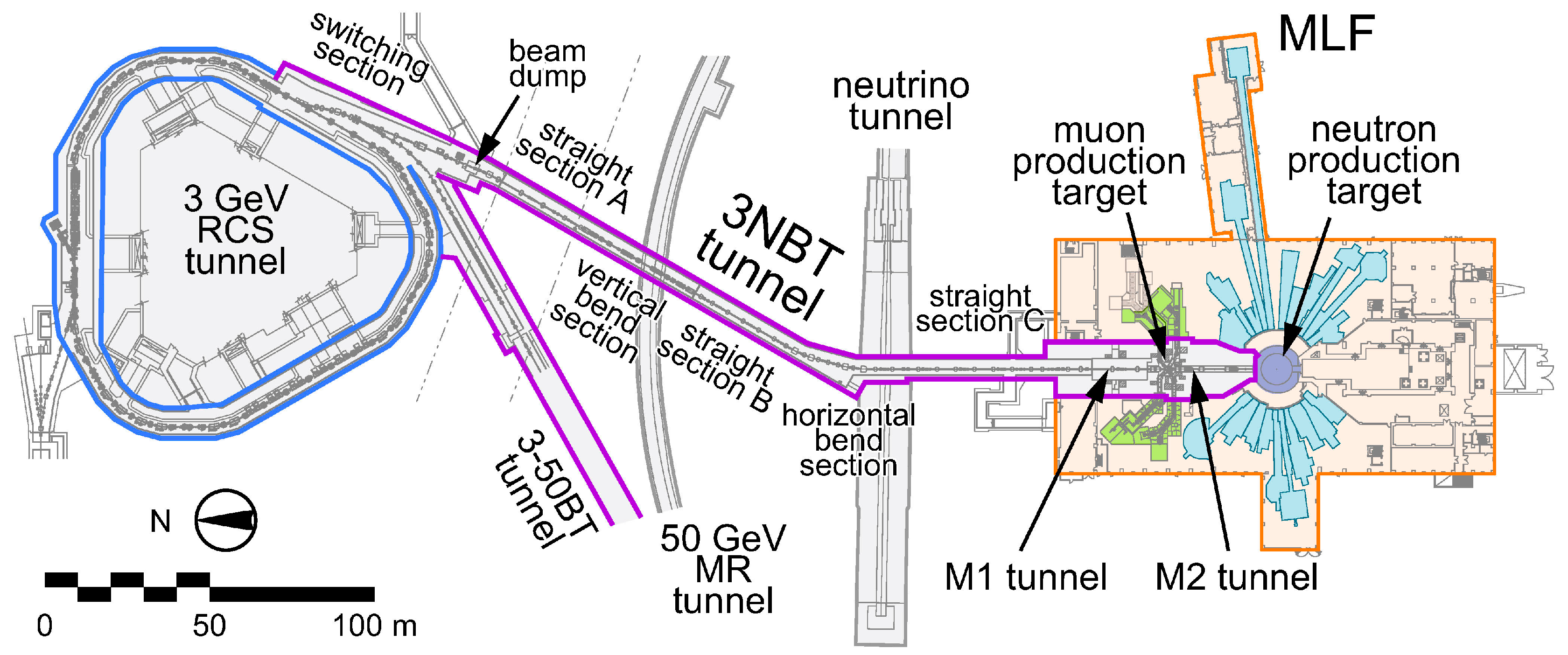
:1. Overview of the Muon Science Establishment
1.1. Muon Science Facility with Tandem-Type Production Graphite Target
1.2. Building Structure and Maintenance
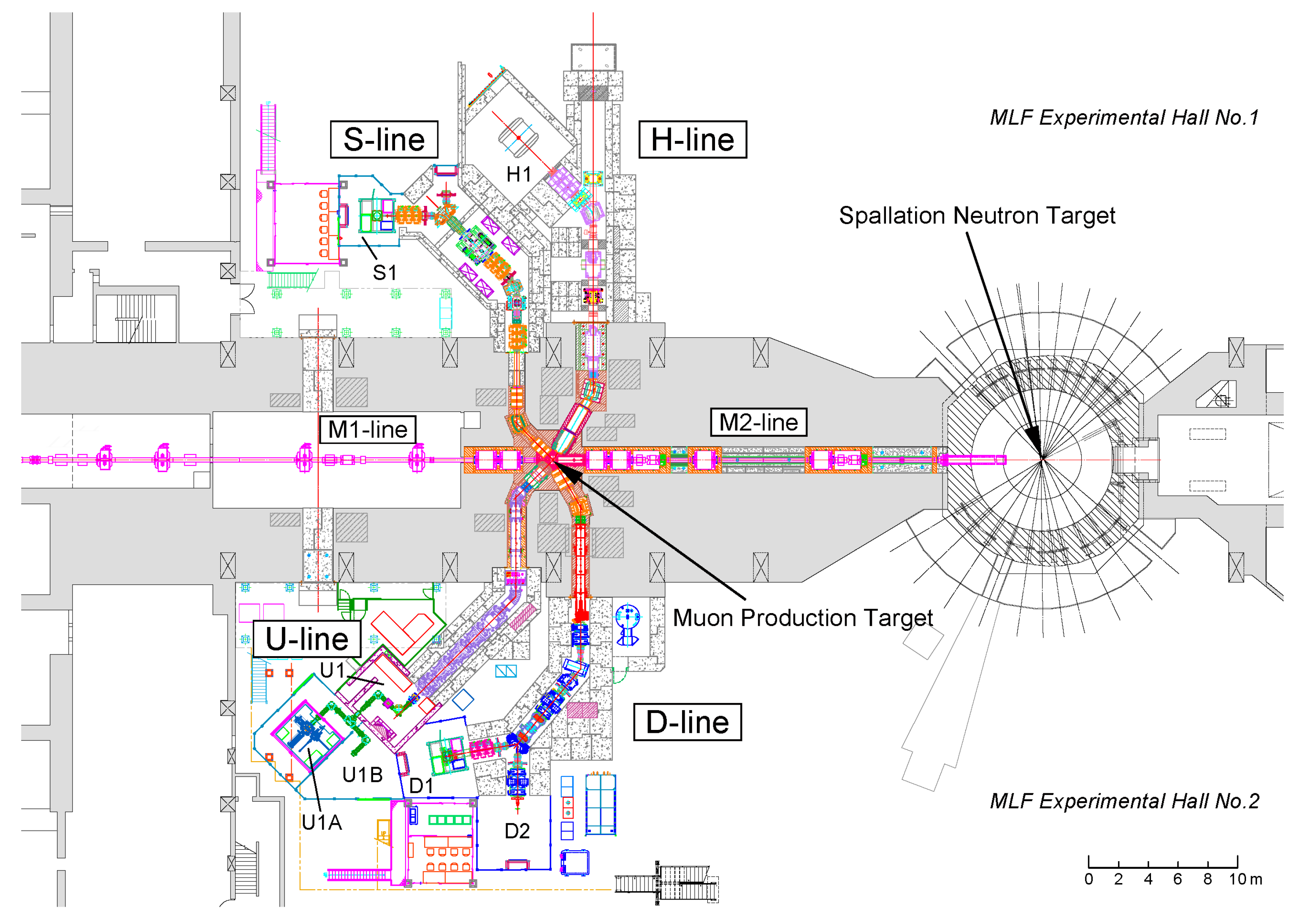
1.3. Muon Beamlines
2. Muon Target
2.1. Overview of the Muon Target
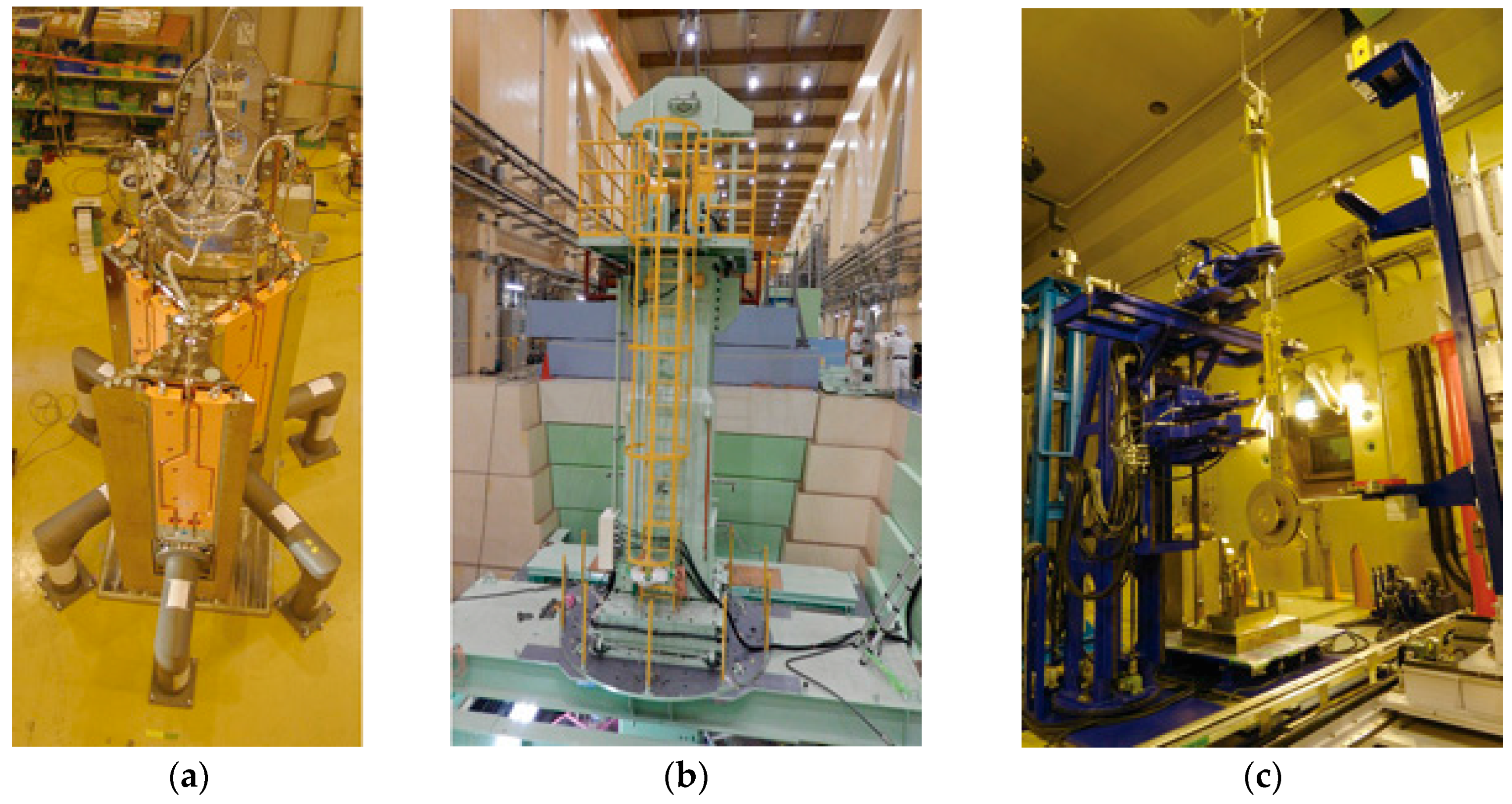
2.2. Fixed Muon Target
2.3. Rotating Muon Target
2.4. Scrapers
3. Muon Beamlines
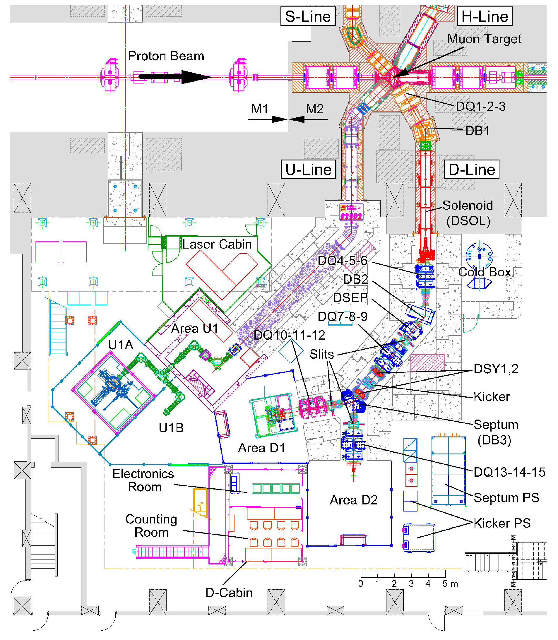
3.1. D-Line
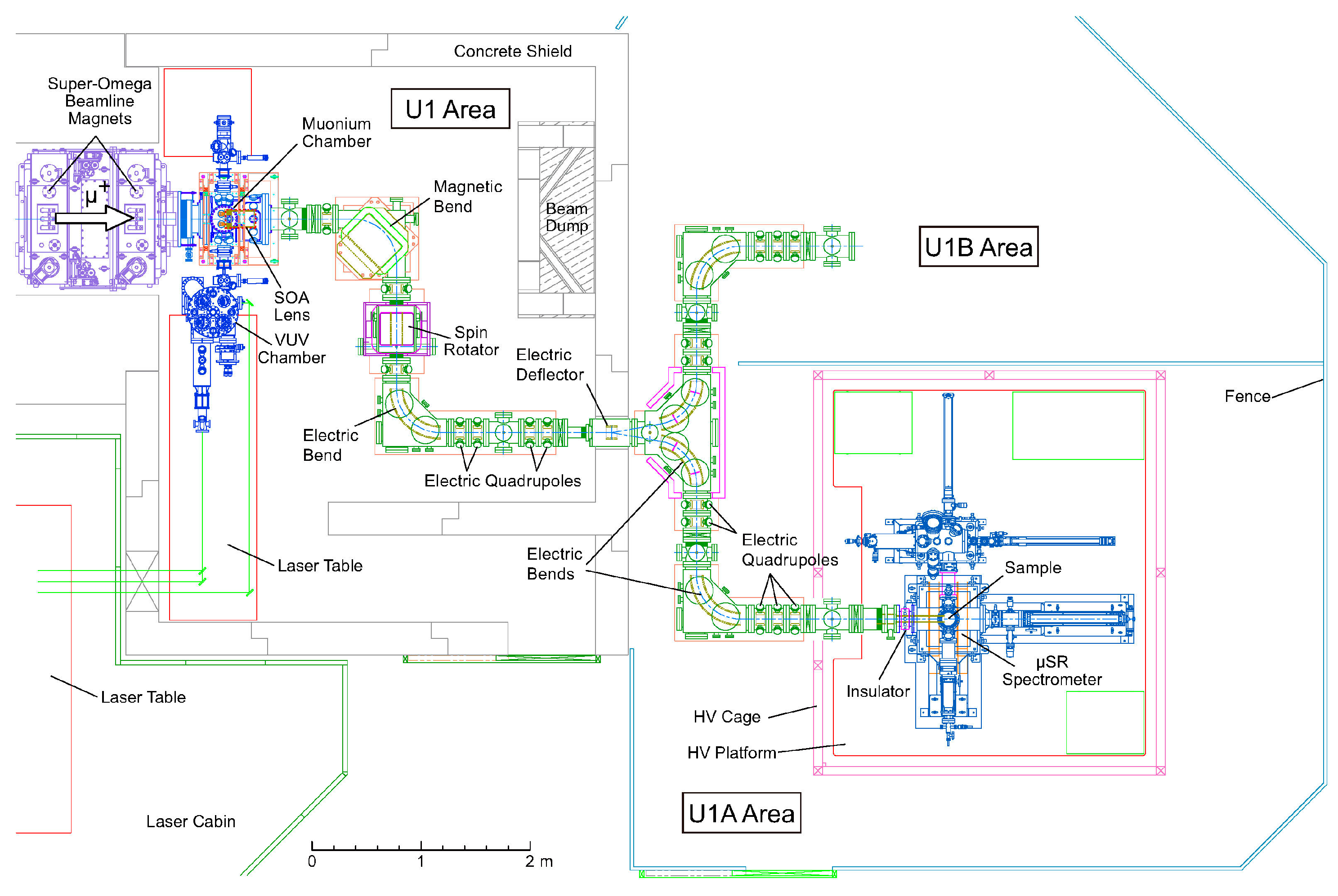
3.2. U-Line
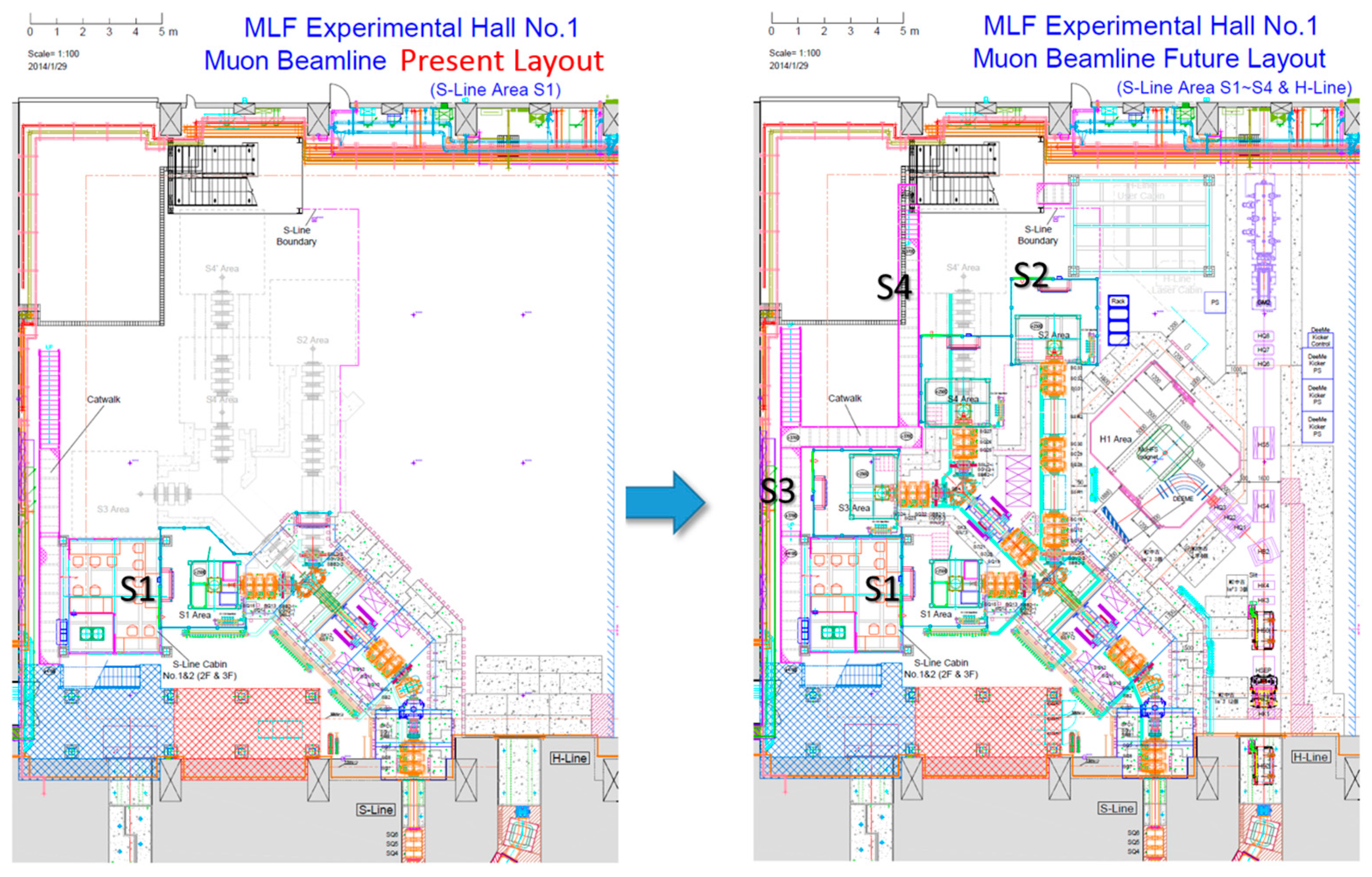
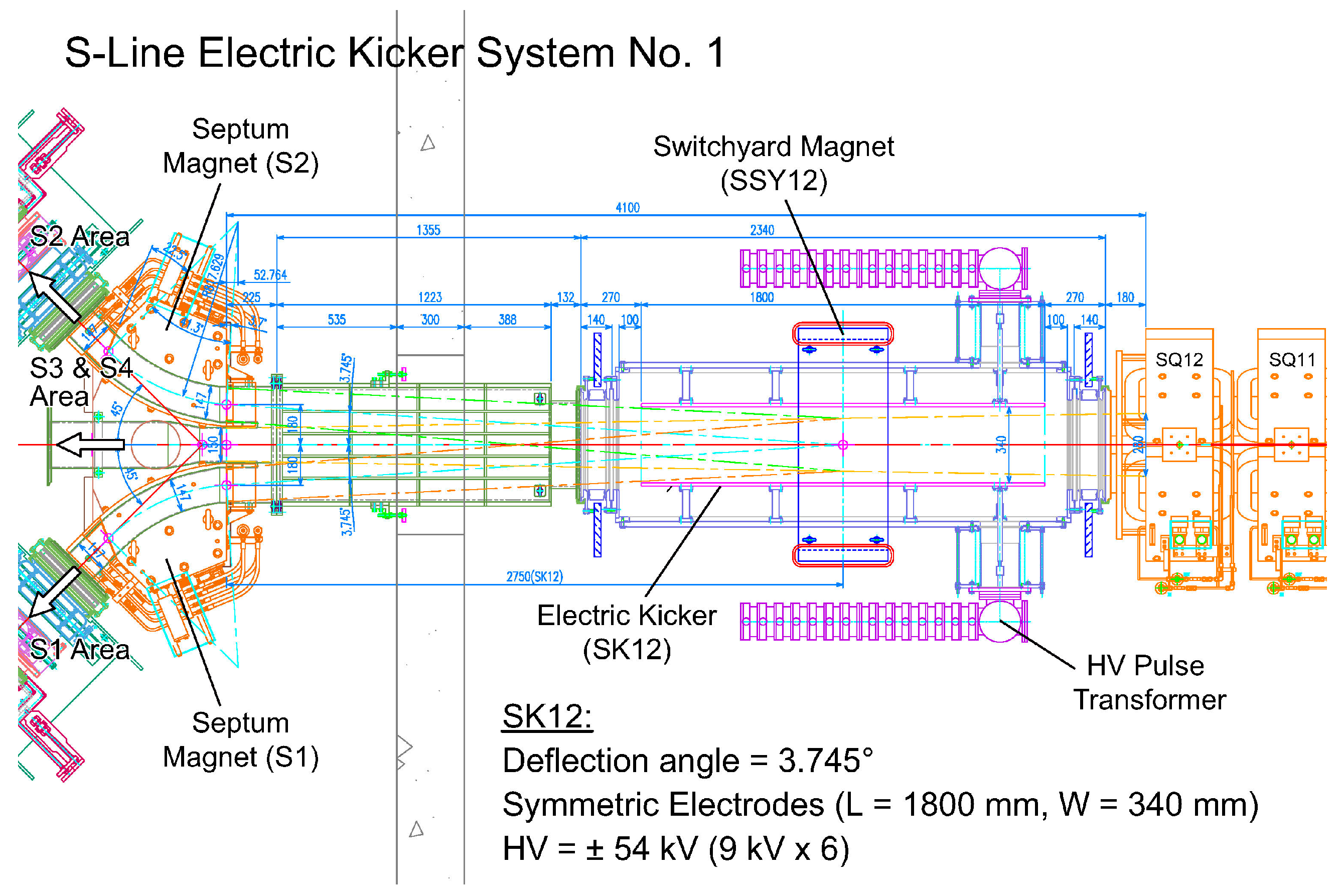
3.3. S-Line
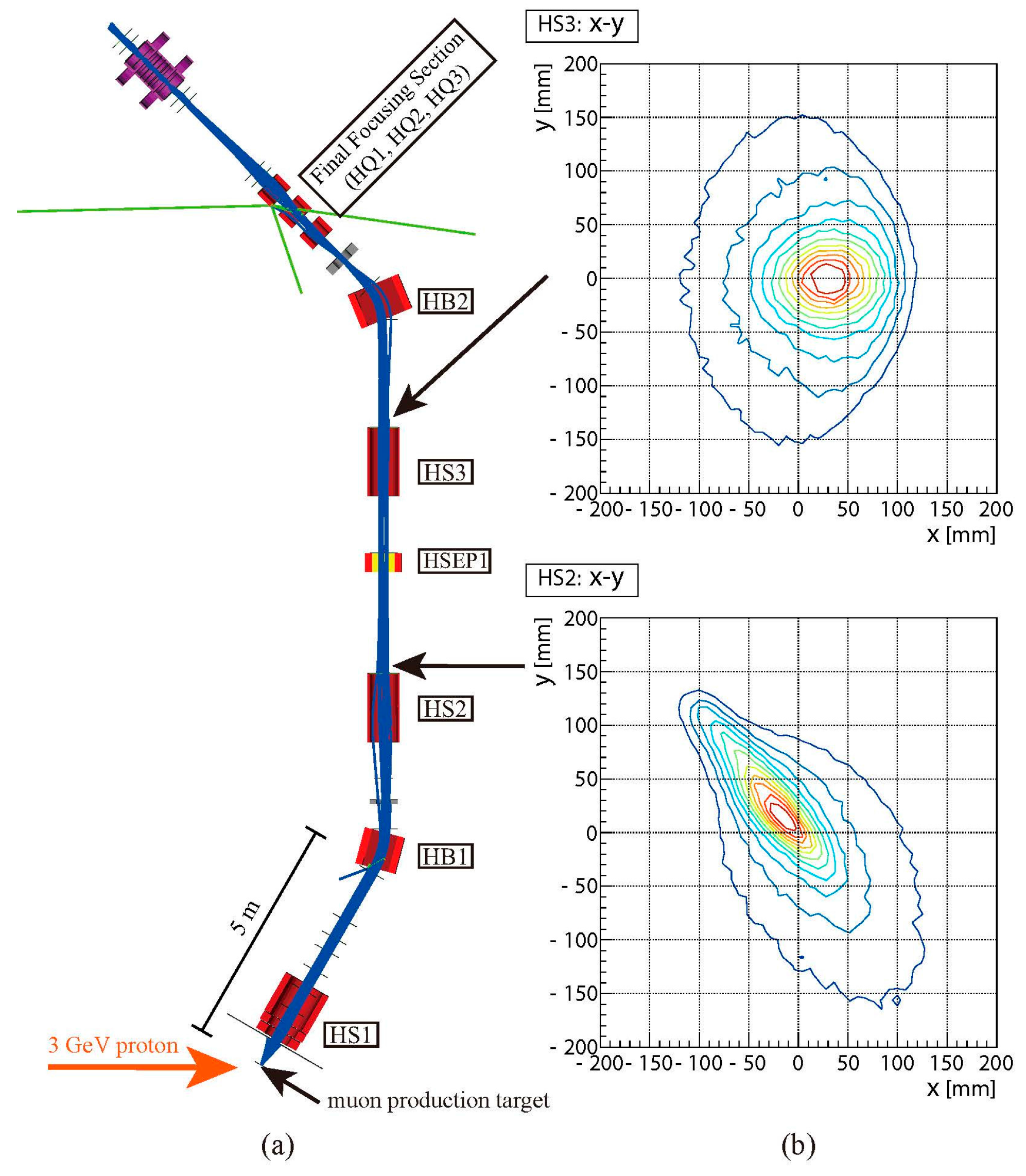
3.4. H-Line
4. Muon Experiment Instruments
4.1. µSR Spectrometers
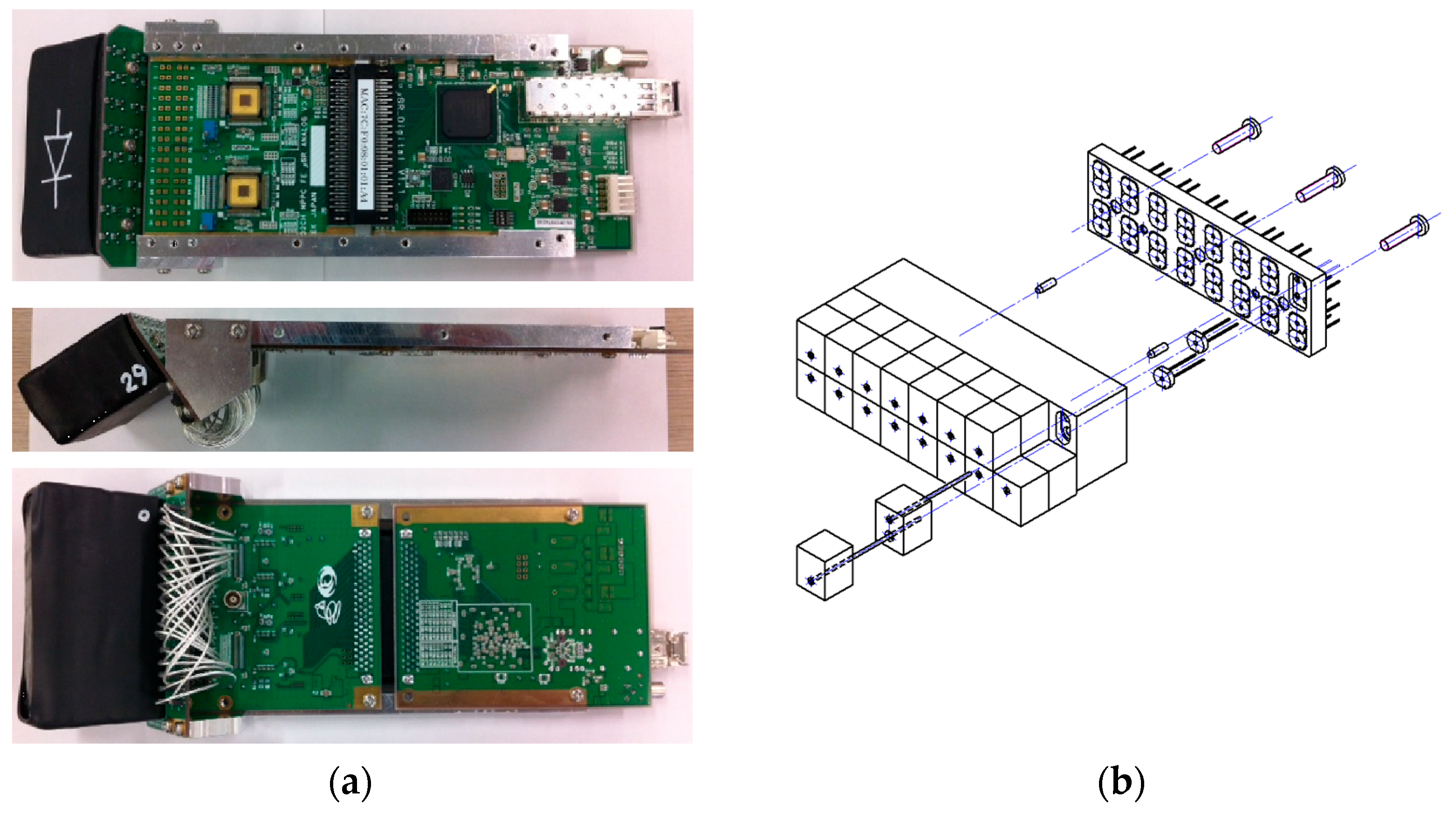
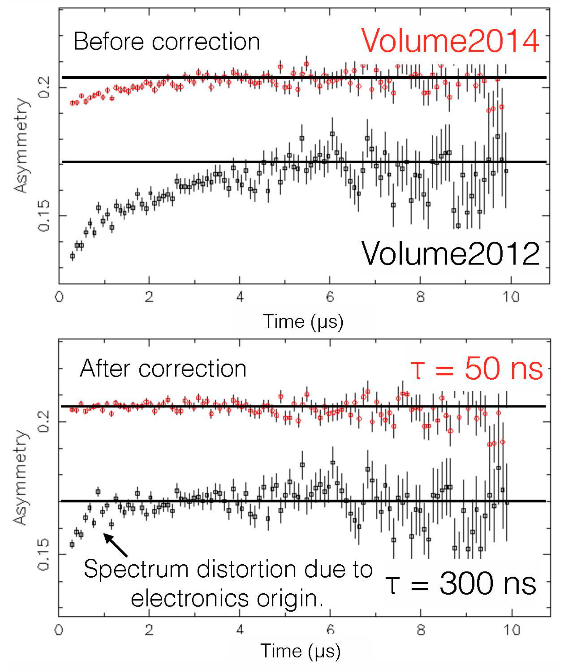
4.2. µSR Spectrometer for USMs
5. Recent Muon Application Highlights
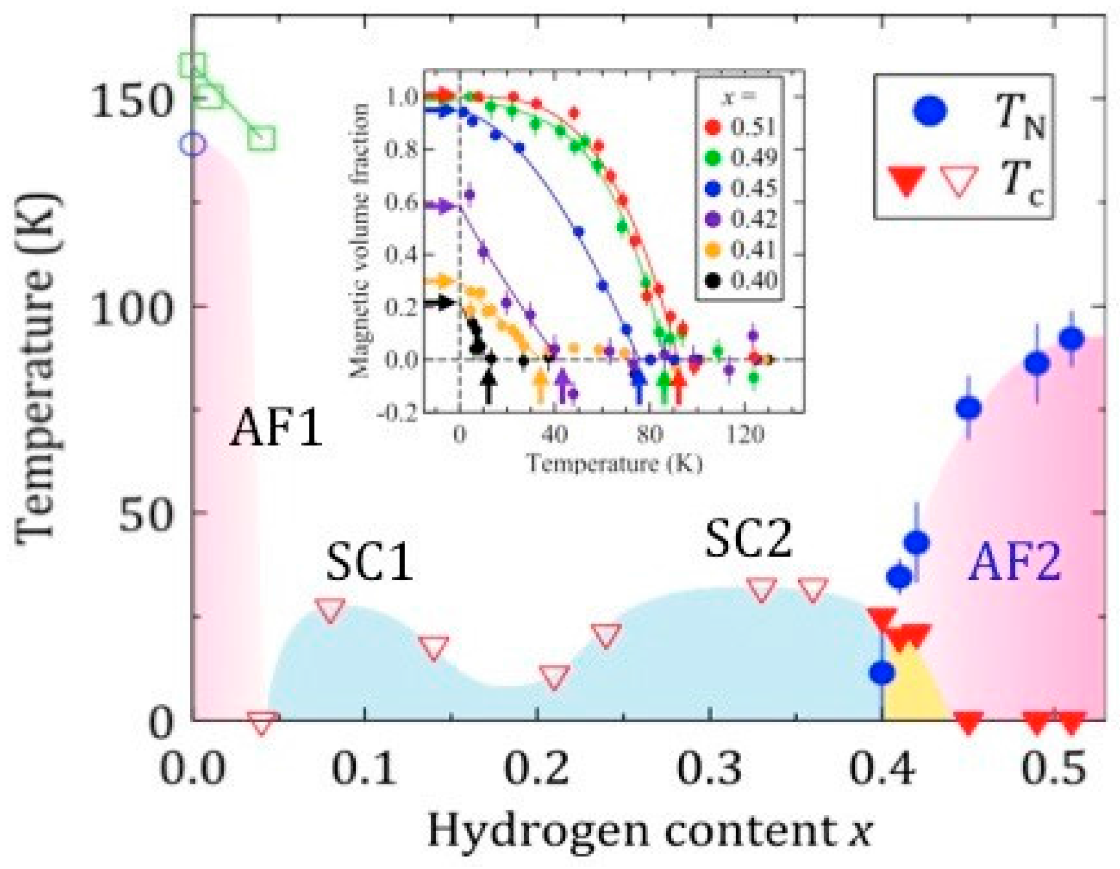
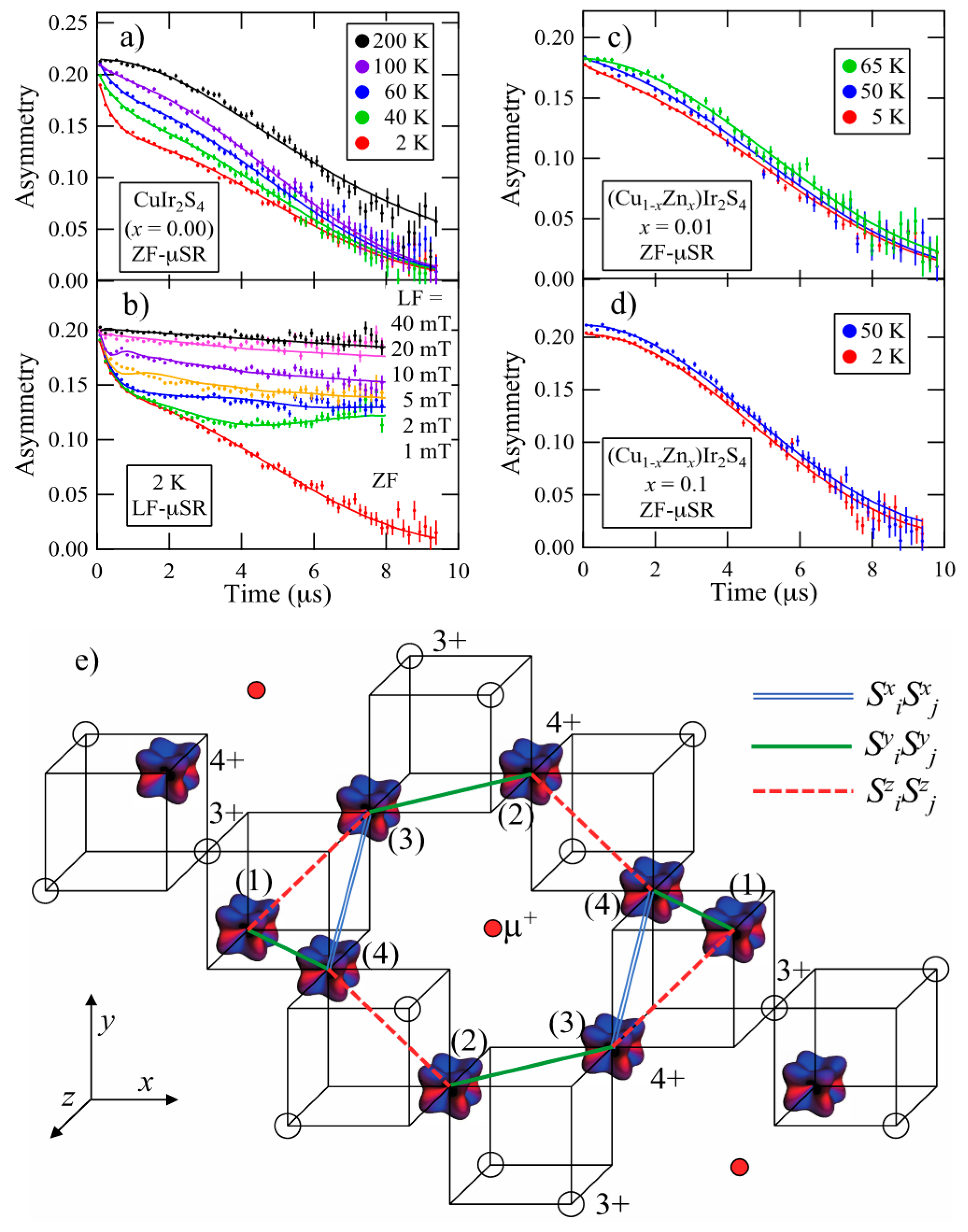
5.1. µSR Studies in Condensed Matter Physics and the Materials Sciences
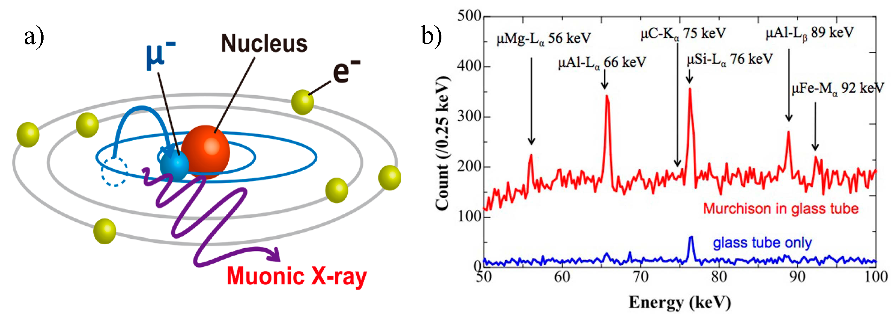
5.2. Non-Invasive Element Analysis
Acknowledgments
Author Contributions
Conflicts of Interest
References
- Miyake, Y.; Nishiyama, K.; Kawamura, N.; Makimura, S.; Strasser, P.; Shimomura, K.; Beveridge, J.L.; Kadono, R.; Fukuchi, K.; Sato, N.; et al. Status of J-PARC muon science facility at the year of 2005. Physica B 2006, 374, 484–487. [Google Scholar] [CrossRef]
- Heidenreich, G.; Baumann, P.; Geissler, A.; Strinning, A.; Wagner, W. Improvement of the operational reliability of target-E. PSI Sci. Rep. 1998, VI, 16. [Google Scholar]
- Nagamine, K.; Matsuzaki, T.; Ishida, K.; Watanabe, I.; Nakamura, S.N.; Kadono, R.; Kawamura, N.; Sakamoto, S.; Iwasaki, M.; Tanase, M.; et al. New RIKEN-RAL pulsed µCF facility and X-ray studies on DT-µCF. Hyperfine Interact. 1996, 101, 521–538. [Google Scholar] [CrossRef]
- TOYO TANSO. Available online: http://www.toyotanso.co.jp/index_en (accessed on 13 June 2017).
- Makimura, S.; Miyake, Y.; Kawamura, N.; Strasser, P.; Koda, A.; Shimomura, K.; Fujimori, H.; Nishiyama, K.; Kato, M.; Nakahara, K.; et al. Present status of construction for the muon target in J-PARC. Nucl. Instrum. Meth. A 2009, 600, 146–149. [Google Scholar] [CrossRef]
- Makimura, S.; Shimizu, R.; Kawamura, N.; Miyake, Y.; Kobayashi, Y.; Koda, A.; Kato, M.; Fujimori, H.; Shimomura, K.; Strasser, P.; et al. Report for muon production target with proton beam operation in J-PARC. In Proceedings of the 8th Annual Meeting of Particle Accelerator Society of Japan, Tsukuba, Japan, 1–3 August 2011; Particle Accelerator Society of Japan: Tokyo, Japan, 2011. 45008267. pp. 1188–1191. [Google Scholar]
- Matsuo, H. Irradiation damage in nuclear graphite and carbon material changes in dimension and physical properties caused by neutron irradiation and heat treatment. Graphite 1991, 1991, 290–302. [Google Scholar] [CrossRef]
- Makimura, S.; Kawamura, N.; Kojima, K.M.; Koda, A.; Kurosawa, N.; Shimizu, R.; Strasser, P.; Nakamura, J.; Miyake, Y. Remote-controlled non-destructive measurement for thermal conductivity of highly radioactive isotropic graphite used as the muon production target at J-PARC/MUSE. J. Nucl. Mater. 2014, 450, 110–116. [Google Scholar] [CrossRef]
- Makimura, S.; Kawamura, N.; Kato, M.; Kobayashi, Y.; Miyake, Y.; Koda, A.; Fujimori, H.; Shimomura, K.; Strasser, P.; Nishiyama, K.; et al. Remotely controlled replacement of highly radioactive components in J-PARC/MUSE. In Proceedings of the 7th Annual Meeting of Particle Accelerator Society of Japan, Himeji, Japan, 4–6 August 2010; Particle Accelerator Society of Japan: Tokyo, Japan, 2010. 44081307. pp. 479–483. [Google Scholar]
- Makimura, S.; Kawamura, N.; Onizawa, S.; Matsuzawa, Y.; Tabe, M.; Kobayashi, Y.; Shimizu, R.; Taniguchi, Y.; Fujimori, H.; Ikedo, Y.; et al. Development of muon rotating target at J-PARC/MUSE. J. Radioanal. Nucl. Chem. 2015, 305, 811–815. [Google Scholar] [CrossRef]
- Iwase, H.; Niita, T. Development of general-purpose particle and heavy ion transport Monte Carlo code. J. Nucl. Sci. Technol. 2002, 39, 1142–1151. [Google Scholar] [CrossRef]
- Kawamura, N.; Makimura, M.; Strasser, P.; Koda, A.; Fujimori, H.; Nishiyama, K.; Miyake, Y. Design strategy for devices under high radiation field in J-PARC muon facility. Nucl. Instrum. Meth. A 2009, 600, 114–116. [Google Scholar] [CrossRef]
- Makimura, S.; Ozaki, H.; Okamura, H.; Futakawa, M.; Naoe, T.; Miyake, Y.; Kawamura, N.; Nishiyama, K.; Kawai, M. The present status of R&D for the muon target at J-PARC: The development of silver-brazing method for graphite. J. Nucl. Mater. 2008, 377, 28–33. [Google Scholar] [CrossRef]
- Makimura, S.; Kawamura, N.; Onizawa, S.; Matsuzawa, Y.; Tabe, M.; Kobayashi, Y.; Shimizu, R.; Fujimori, H.; Ikedo, Y.; Kadono, R.; et al. Present status of muon production target at J-PARC/MUSE. JPS Conf. Proc. 2015, 8, 051002. [Google Scholar] [CrossRef]
- Makimura, S.; Matoba, S.; Kawamura, N.; Onizawa, S.; Matsuzawa, Y.; Tabe, M.; Kobayashi, Y.; Fujimori, H.; Ikedo, Y.; Koda, A.; et al. Present status of muon rotating target at J-PARC/MUSE. In Proceedings of the 12th Annual Meeting of Particle Accelerator Society of Japan, Tsuruga, Japan, 5–7 August 2015; Particle Accelerator Society of Japan: Tokyo, Japan, 2015; Volume FROM13, pp. 261–264. [Google Scholar]
- JTEKT. Available online: http://www.jtekt.co.jp/e/index.html (accessed on 13 June 2017).
- Bakule, P.; Matsuda, Y.; Miyake, Y.; Strasser, P.; Shimomura, K.; Makimura, S.; Nagamine, K. Slow muon experiment by laser resonant ionization method at RIKEN-RAL muon facility. Spectrochim. Acta B 2003, 58, 1019–1030. [Google Scholar] [CrossRef]
- Strasser, P.; Shimomura, K.; Koda, A.; Kawamura, N.; Fujimori, H.; Makimura, S.; Kobayashi, Y.; Nakahara, K.; Kato, M.; Takeshita, S.; et al. J-PARC decay muon channel construction status. J. Phys. Conf. Ser. 2010, 225, 012050. [Google Scholar] [CrossRef]
- Strasser, P.; Fujimori, H.; Koseki, K.; Hori, K.; Matsumoto, H.; Shimomura, K.; Koda, A.; Kawamura, N.; Makimura, S.; Kato, M.; et al. New muon kicker system for the decay muon beamline at J-PARC. Phys. Procedia 2012, 30, 65–68. [Google Scholar] [CrossRef]
- Miyake, Y.; Ikedo, Y.; Shimomura, K.; Strasser, P.; Nagatomo, T.; Nakamura, J.; Makimura, S.; Kawamura, N.; Fujimori, H.; Koda, A.; et al. Ultra slow muon project at J-PARC, MUSE. JPS Conf. Proc. 2014, 2, 010101. [Google Scholar] [CrossRef]
- Nagamine, K.; Miyake, Y.; Shimomura, K.; Birrer, P.; Marangos, J.P.; Iwasaki, M.; Strasser, P.; Kuga, T. Ultraslow positive-muon generation by laser ionization of thermal muonium from hot tungsten at primary proton beam. Phys. Rev. Lett. 1995, 74, 4811–4814. [Google Scholar] [CrossRef] [PubMed]
- Ikedo, Y.; Miyake, Y.; Shimomura, K.; Strasser, P.; Nishiyama, K.; Kawamura, N.; Fujimori, H.; Makimura, S.; Koda, A.; Ogitsu, T.; et al. Status of the Superomega muon beam line at J-PARC. Phys. Procedia 2012, 30, 34–37. [Google Scholar] [CrossRef]
- Ikedo, Y.; Miyake, Y.; Shimomura, K.; Strasser, P.; Kawamura, N.; Nishiyama, K.; Makimura, S.; Fujimori, H.; Koda, A.; Nakamura, J.; et al. Positron separators in Superomega muon beamline at J-PARC. Nucl. Instrum. Meth. B 2013, 317, 365–368. [Google Scholar] [CrossRef]
- Strasser, P.; Ikedo, Y.; Miyake, Y.; Shimomura, K.; Kawamura, N.; Nishiyama, K.; Makimura, S.; Fujimori, H.; Koda, A.; Nakamura, J.; et al. Superconducting curved transport solenoid with dipole coils for charge selection of the muon beam. Nucl. Instrum. Meth. B 2013, 317, 361–364. [Google Scholar] [CrossRef]
- Oishi, Y.; Okamura, K.; Miyazaki, K.; Saito, N.; Iwasaki, M.; Wada, S. All-solid-state laser amplifiers for intense Lyman-α generation. JPS Conf. Proc. 2014, 2, 010105. [Google Scholar] [CrossRef]
- Nakamura, J.; Oishi, Y.; Saito, N.; Miyazaki, K.; Okamura, K.; Higemoto, W.; Ikedo, Y.; Kojima, K.M.; Strasser, P.; Nagatomo, T.; et al. Optimal crossed overlap of coherent vacuum ultraviolet radiation and thermal muonium emission for μSR with the Ultra Slow Muon. J. Phys. Conf. Ser. 2015, 551, 012066. [Google Scholar] [CrossRef]
- Strasser, P.; Ikedo, Y.; Makimura, S.; Nakamura, J.; Nishiyama, K.; Shimomura, K.; Fujimori, H.; Adachi, T.; Koda, A.; Kawamura, N.; et al. Design and construction of the ultra-slow muon beamline at J-PARC/MUSE. J. Phys. Conf. Ser. 2015, 551, 012065. [Google Scholar] [CrossRef]
- Shimomura, K. Possibility of precise measurement of muonium HFS at J-PARC MUSE. AIP Conf. Proc. 2011, 1382, 245–247. [Google Scholar] [CrossRef]
- Aoki, M.; DeeMe Collaboration. An experimental search for muon-electron conversion in nuclear field at sensitivity of 10−14 with a pulsed proton beam. AIP Conf. Proc. 2012, 1441, 599–601. [Google Scholar] [CrossRef]
- Saito, N.; J-PARC g−2/EDM Collaboration. A novel precision measurement of muon g-2 and EDM at J-PARC. AIP Conf. Proc. 2012, 1467, 45–56. [Google Scholar] [CrossRef]
- G4beamline. Available online: http://public.muonsinc.com/ (accessed on 13 June 2017).
- Higemoto, W.; Ito, T.U.; Ninomiya, K.; Heffner, R.H.; Shimomura, K.; Nishiyama, K.; Miyake, Y. Muon beam slicer at J-PARC MUSE. Phys. Procedia 2012, 30, 30–33. [Google Scholar] [CrossRef]
- Hiraishi, M.; Iimura, S.; Kojima, K.M.; Yamaura, J.; Hiraka, H.; Ikeda, K.; Miao, P.; Ishikawa, Y.; Torii, S.; Miyazaki, M.; et al. Bipartite magnetic parent phases in the iron oxypnictide superconductor. Nat. Phys. 2014, 10, 300–303. [Google Scholar] [CrossRef]
- Iimura, S.; Matuishi, S.; Sato, H.; Hanna, T.; Muraba, Y.; Kim, S.W.; Kim, J.E.; Takata, M.; Hosono, H. Two-dome structure in electron-doped iron arsenide superconductors. Nat. Commun. 2012, 3, 943. [Google Scholar] [CrossRef] [PubMed]
- Fujiwara, N.; Tsutsumi, S.; Iimura, S.; Matsuishi, S.; Hosono, H.; Yamakawa, Y.; Kontani, H. Detection of antiferromagnetic ordering in heavily doped LaFeAsO1−xHx pnictide superconductors using nuclear-magnetic-resonance techniques. Phys. Rev. Lett. 2013, 111, 097002. [Google Scholar] [CrossRef] [PubMed]
- Kojima, K.M.; Kadono, R.; Miyazaki, M.; Hiraishi, M.; Yamauchi, I.; Koda, A.; Tsuchiya, Y.; Suzuki, H.S.; Kitazawa, H. Magnetic frustration in iridium spinel compound CuIr2S4. Phys. Rev. Lett. 2014, 112, 087203. [Google Scholar] [CrossRef]
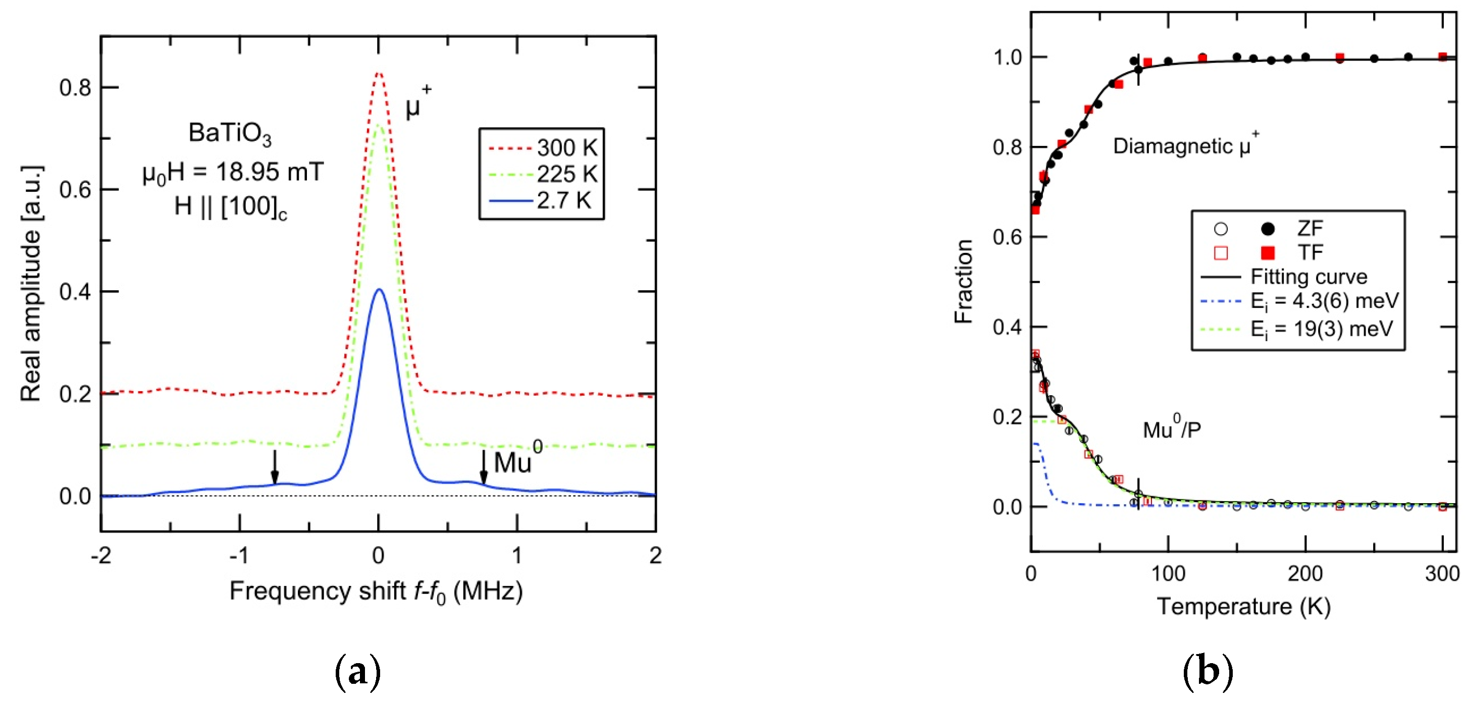
- Ito, T.U.; Higemoto, W.; Matsuda, T.D.; Koda, A.; Shimomura, K. Shallow donor level associated with hydrogen impurities in undoped BaTiO3. Appl. Phys. Lett. 2013, 103, 042905. [Google Scholar] [CrossRef]
- Terada, K.; Ninomiya, N.; Osawa, T.; Tachibana, S.; Miyake, Y.; Kubo, M.K.; Kawamura, N.; Higemoto, W.; Tsuchiyama, A.; Ebihara, M.; et al. A new X-ray fluorescence spectroscopy for extraterrestrial materials using a muon beam. Sci. Rep. 2014, 4, 5072. [Google Scholar] [CrossRef] [PubMed]


| 300 kW | 500 kW | 1 MW | |
|---|---|---|---|
| Shaft Simulation | 71 °C | 84 °C | 115 °C |
| Shaft Measurement | 78 °C | 95 °C | - |
| Graphite Simulation | 400 °C | 475 °C | 620 °C |
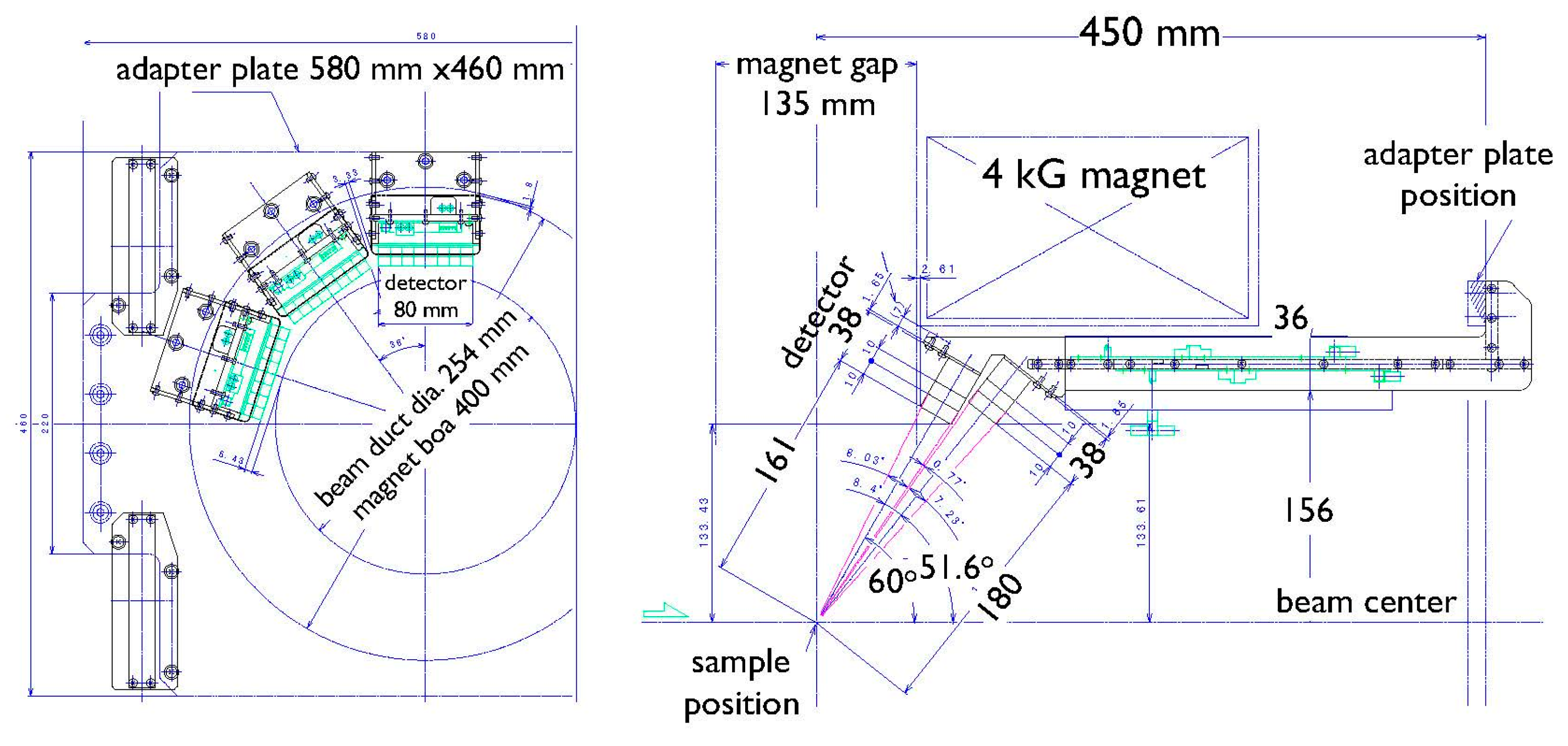
| Magnets | |
|---|---|
| Horizontal field BZ (//beam) or Bx (┴beam) | Maximum 0.4 T (1000 A, 100 V) |
| Bore and gap | ø400, 135 mm |
| Homogeneity | 0.1% ø20 mm, 1% ø50 mm |
| Stability | Drift < 0.01% for 8 h Ripple Vp–p < 0.01% |
| Vertical field By (┴beam, vertical) | Maximum 14 mT (25 mT with optional coils) (100 A, 40 V) |
| Homogeneity | 0.1% ø20 mm, 1% ø50 mm |
| Stability | Drift < 0.05% Ripple Vp–p < 0.1% |
| Correction field coils used to achieve a zero field (CCx, y, z) | Maximum 1 mT (10 A, 20 V) |
| Homogeneity | 0.5% ø20 mm, 10% ø50 mm |
| Positron Counters | |
| Number of channels | 32 channels × 40 Kalliope units = 1280 channels (640 pairs) |
| Detector solid angle | 21.2% of 4π (2 × 8 array of 10 mm × 12 mm scintillator cubes: covers an area of 1920 mm2 at 180 mm and 161 mm from the sample) |
| Sample Insert Area | |
| Bore and gap | ø254, 135 mm |
© 2017 by the authors. Licensee MDPI, Basel, Switzerland. This article is an open access article distributed under the terms and conditions of the Creative Commons Attribution (CC BY) license (http://creativecommons.org/licenses/by/4.0/).
Share and Cite
Higemoto, W.; Kadono, R.; Kawamura, N.; Koda, A.; Kojima, K.M.; Makimura, S.; Matoba, S.; Miyake, Y.; Shimomura, K.; Strasser, P. Materials and Life Science Experimental Facility at the Japan Proton Accelerator Research Complex IV: The Muon Facility. Quantum Beam Sci. 2017, 1, 11. https://doi.org/10.3390/qubs1010011
Higemoto W, Kadono R, Kawamura N, Koda A, Kojima KM, Makimura S, Matoba S, Miyake Y, Shimomura K, Strasser P. Materials and Life Science Experimental Facility at the Japan Proton Accelerator Research Complex IV: The Muon Facility. Quantum Beam Science. 2017; 1(1):11. https://doi.org/10.3390/qubs1010011
Chicago/Turabian StyleHigemoto, Wataru, Ryosuke Kadono, Naritoshi Kawamura, Akihiro Koda, Kenji M. Kojima, Shunsuke Makimura, Shiro Matoba, Yasuhiro Miyake, Koichiro Shimomura, and Patrick Strasser. 2017. "Materials and Life Science Experimental Facility at the Japan Proton Accelerator Research Complex IV: The Muon Facility" Quantum Beam Science 1, no. 1: 11. https://doi.org/10.3390/qubs1010011