
High Power Laser Facilities at the Kansai Photon Science Institute
by
 ,
,
Kiminori Kondo
*, 
Wataru Utsumi
,
Masaki Kando
,
Masaharu Nishikino
,
Ryuji Itakura
and
Hiromitsu Kiriyama
Kansai Photon Science Institute, Quantum Beam Science Directorate, National Institutes for Quantum and Radiological Science and Technology 8-1-7 Umemidai, Kizugawa, Kyoto 619-0215, Japan
*
Author to whom correspondence should be addressed.
Quantum Beam Sci. 2017, 1(1), 7; https://doi.org/10.3390/qubs1010007
Submission received: 27 March 2017
/
Revised: 26 May 2017
/
Accepted: 30 May 2017
/
Published: 7 June 2017
(This article belongs to the Collection Facilities)
Abstract
:At the Kansai Photon Science Institute (KPSI, Kyoto, Japan), there are three unique high-power laser facilities. Here, we introduce the features of each facility and some experimental studies, which will be useful to users as a reference.
1. Introduction
In April 2016, part of the Quantum Beam Science Directorate, which includes the Kansai Photon Science Institute (KPSI, Kyoto, Japan), was separated from the Japan Atomic Energy Agency (JAEA) and unified into a new society, the National Institute for Quantum and Radiological Science and Technology (QST) (Chiba-shi, Japan). Thus, our high-power laser facilities launched a new plan following this change. Under QST, the mission of research and development has not always been related to nuclear technology. It could be for science and technology that could produce an innovative technology and/or business. Therefore, high-power laser technology is also one of the important technologies that is being studied at the national institute. Now, KPSI belongs to QST; thus, for each laser facility, it is very important to produce impressive results and be used as a user facility. In this paper, we will describe the present status of our high-power laser facilities: the PW (Peta Watt) laser facility, the J-KAREN-P (Japan-Kansai Advanced Relativistic Engineering Petawatt); the X-ray laser facility (XRL), excited by an energetic repeatable glass laser, TOPAZ (Twin Optical Amplifiers using Zigzag slab); and the high-repetition rate, high peak power laser system, QUADRA-T (Quality Ultra Advanced Radiation source Terahertz radiation) for strong THz generation. Figure 1 displays a photo of the KPSI Kizu site; the KPSI Harima site is a SOR (Synchrotron Orbit Radiation) user facility site of SPring-8. The laser facilities are placed in the laboratory building, as shown in Figure 1.
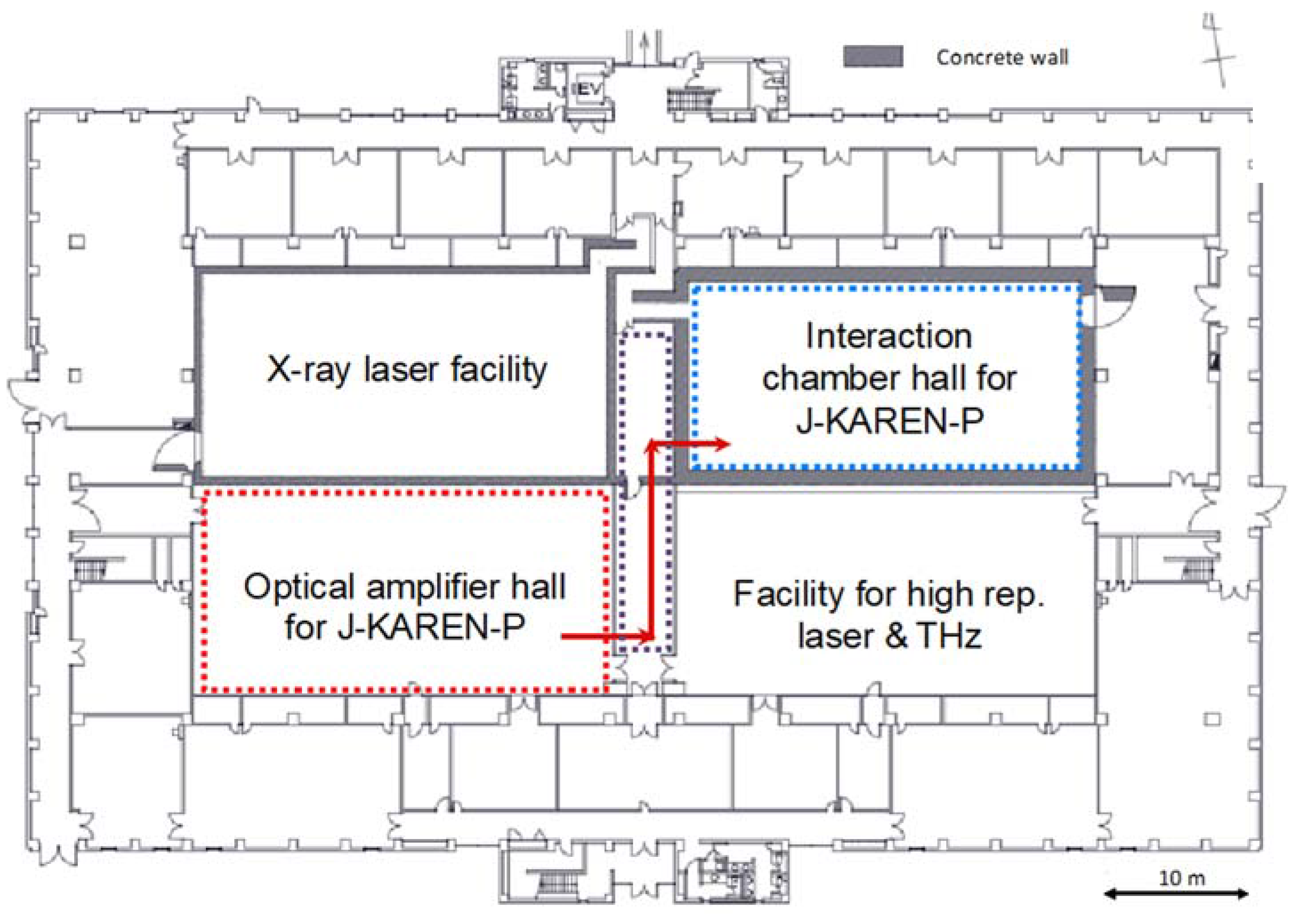
In Figure 2, a schematic top view of the laboratory building is shown. In this building, there are not only four experimental halls, but also other somewhat smaller rooms that are used for various activities, such as experiments. The J-KAREN-P facility occupies two halls. One is for the optical power amplifier chain, which can yield more than 60 J per pulse at a repetition rate of 0.1 Hz; the other is for the laser plasma interaction, which is illustrated in Figure 3. The large pulse compressor of J-KAREN-P is placed in the interaction chamber hall to reduce the number of large optics. In this interaction chamber hall, there is a microtron, which is an electron cyclotron accelerator. The wall thickness of this hall is 1 m acting as a radiation shield for the accelerator, while for the XRL facility hall, the thickness of the wall is 50 cm. The optical amplifier hall of J-KAREN-P and the hall for the high-repetition-rate laser facilities, QUADRA-T and THz, are halls of higher than class 1000 clearness to avoid optical damage caused by dust. These facilities are currently open for users.
In this paper, these three high-power laser facilities are introduced.
2. PW Laser Facility J-KAREN-P
2.1. Ultrashort High-Peak-Power Laser J-KAREN-P
The J-KAREN laser facility [1] delivers an on-target, single-shot intensity of 1021 W/cm2 with a temporal contrast of about 1012. J-KAREN has been upgraded to J-KAREN-P to realize pulses with a PW-level on-target peak power at a repetition rate of 0.1 Hz with an intensity capability of over 1022 W/cm2. Such progress in high-field science will give rise to new applications and breakthroughs, which include relativistic particle acceleration, bright X-ray source generation, and nuclear activation. Many other interesting features including relativistic transparency and radiation friction could be investigated with higher intensity laser pulses.
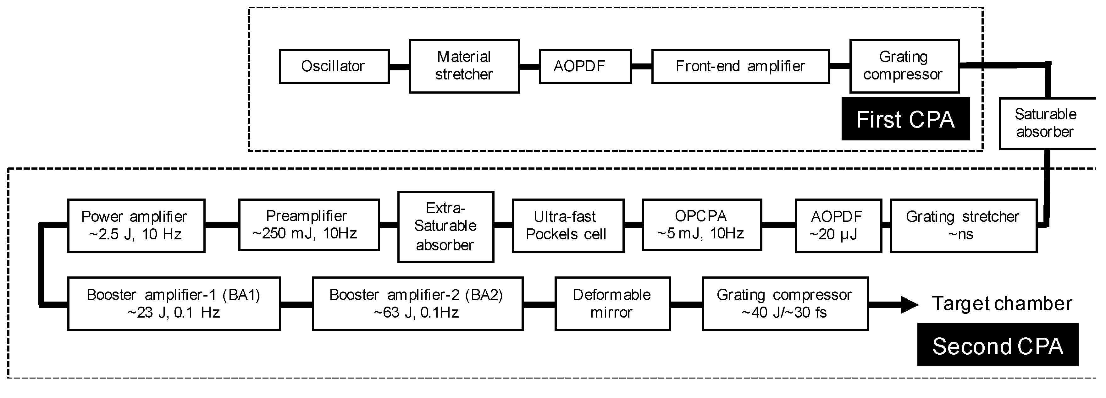
A schematic of J-KAREN-P laser system is shown in Figure 4. The output pulses with a high temporal contrast and uniform spatial profile from the power amplifier are up-collimated and enter booster amplifier 1 (BA1), which uses an 80-mm diameter Ti:sapphire crystal, and is pumped with approximately 50 J from 2 commercial Nd:glass green lasers at a repetition rate of 0.1 Hz. The pulses from BA1 are then amplified in the booster amplifier 2 (BA2), which uses a 120-mm diameter Ti:sapphire crystal, and are pumped with approximately 100 J from 4 commercial Nd:glass green lasers at a repetition rate of 0.1 Hz. A deformable mirror is installed in the laser chain to correct the wavefront distortion. The amplified pulses are up-collimated to a diameter of about 250 mm and are finally compressed in the compressor consisting of 4 1480 grooves/mm, gold-coated gratings of 565 × 360 mm2.
A maximum output energy of 23 J has been achieved with an incident pump energy of 47 J with a good conversion efficiency of 49% from BA1. The near-field beam profile has a homogeneous and uniform spatial intensity distribution. The amplified spectrum from the Ti:sapphire amplifiers is red-shifted because of saturation. As a mitigating measure, the amplifier input spectrum is therefore blue-shifted by tuning the phase-match setting of the beta-barium borate(BBO) crystals in the optical chirped-pulse parametric amplification (OPCPA) amplifier.
Figure 5 shows the dependence of the output energy from BA2 on the total pump energy at a repetition rate of 0.1 Hz. A maximum output energy of 63 J is achieved with an incident energy of 92 J. From Figure 5 it is clearly seen that the experimental data fits the simulation. Figure 6 displays the typical spatial profile of the laser beam from BA2. The beam diameter is 80 mm. The profile has a homogeneous and uniform intensity distribution.
After BA2, the wavefront distortions are corrected with the deformable mirror. The beam is then sent into the pulse compressor. The measured spectrum has a bandwidth of about 50 nm at FWHM (full-width at half-maximum). A recompressed pulse duration of less than 30 fs is obtained. The on-target peak power is expected to be PW-level at a repetition rate of 0.1 Hz because the beamline throughput from the laser room to the target chamber, including the compressor, is about 60%. With an f/1.4 off-axis parabolic mirror, the focal spot of 1.32 × 1.37 µm2 at the FWHM includes 32% of the energy. This results in a focused peak intensity of 1022 W/cm2 with a power level of 0.3 PW. The contrast is measured with a third-order cross-correlator for the laser pulse without pumping the booster amplifiers. The contrast at less than 200 ps before the main pulse is 3 × 10⁻¹² (detection limited). The contrast at 100, 50, 10, and 5 ps before the main pulse are about 10−11, 6 × 10⁻¹⁰, and 8 × 10⁻⁹, respectively.
2.2. Relativistic Plasma Experiment at Interaction Chamber Room
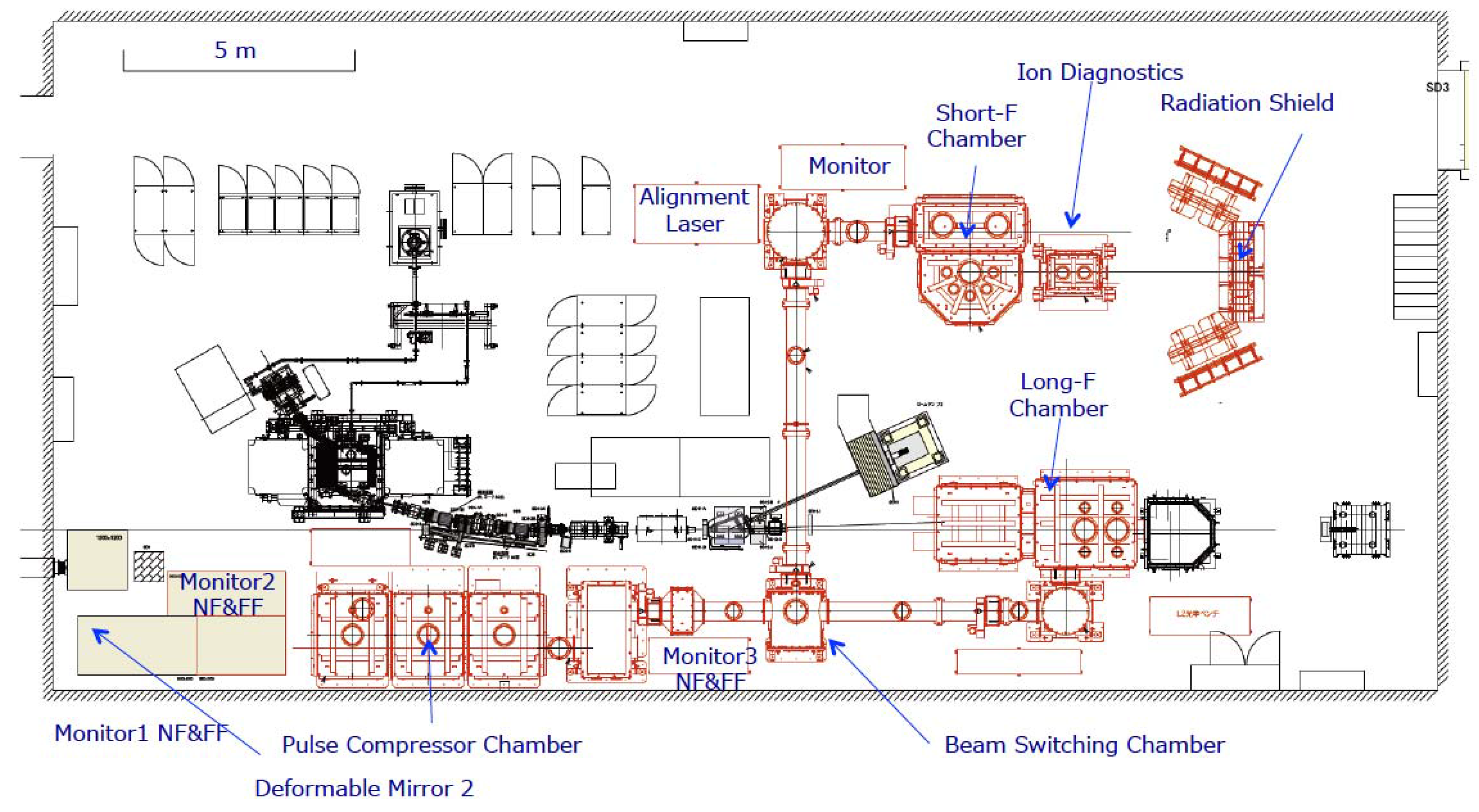
The experimental hall of J-KAREN-P is a radiation-controlled area surrounded by 1-m-thick concrete walls for ionizing radiation shielding. In the hall, the laser beamline, including a beam expander, pulse compressor, two target chambers, alignment lasers, and monitor systems, as well as a 150-MeV electron accelerator microtron, are installed. In this section, we review the capabilities of the two target chambers (short-F (Focal length) and long-F chambers) and review the planned and possible experiments.
2.2.1. Laser Beam Characterization
It is very important to characterize the laser beam performance, such as pulse duration and pulse contrast at the final destination—the target. We reflect a small fraction of the compressed main laser beam inside the target chamber with a 1-inch (2.45 cm) mirror to the detectors. Usually, a homemade TG-FROG (transient-grating, frequency-resolved optical gating) is used to adjust the pulse duration by moving the grating separation and input angle. Then, the typical pulse duration is 30 fs (FWHM) and the contrast ratio is 10−12, 200 ps before the main peak. The full beam characterization will be planned at the long-f chamber equipped with f/10 focusing optics.
Each target chamber equips a focal spot monitor composed of a microscope objective and a 12-bit imaging camera mounted on three-axis stages. Wavefront correction is performed using a deformable mirror ILAO95 (Imagine Optic, Orsay, France) and a Shack-Hartmann sensor HASO3 32 (Imagine Optic). The beam size at the deformable mirror is nominally 80 mm before the beam expanders and pulse compressor. The Strehl ratio determined by the final focus spot is approximately 0.4.
2.2.2. Short-F Chamber
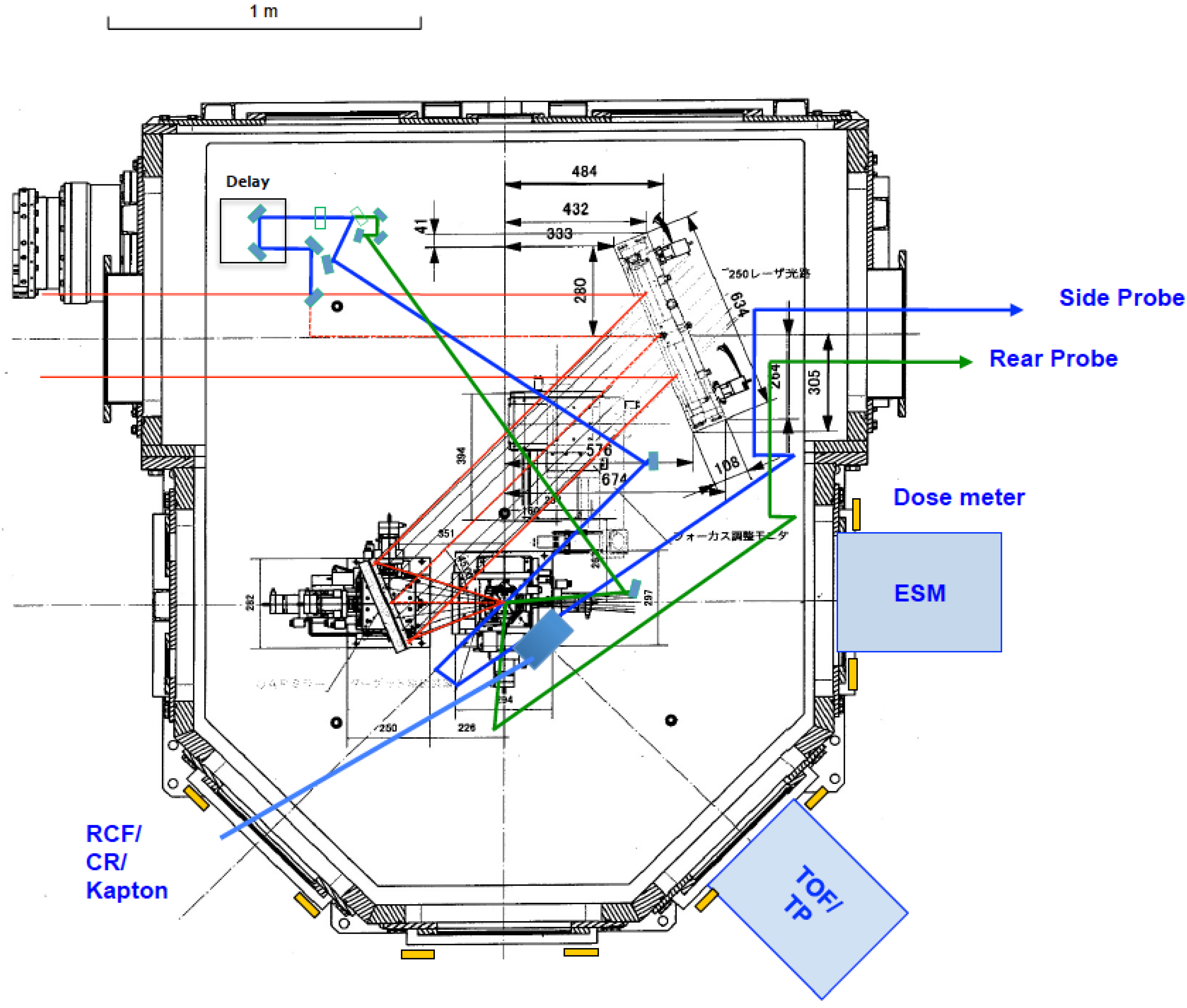
This target chamber has a semi-hexagonal shape to allow for several ports directed to the TCC (target chamber center) where laser pulses are focused and interact with the targets, as shown in Figure 7 and Figure 8. An OAP (off-axis parabolic mirror) with a short focal length (f = 350 mm) is typically installed with an off-axis angle of 45°. The nominal f-number is f/1.4 (f = 350 mm). A focal spot of 1.32 × 1.37 µm2 (FWHM) (encircled energy of 32%) is obtained. Thus, the estimated focused peak intensity reaches 1022 W/cm2 with a power level of 0.3 PW. The target can be either a tape target (aluminum, stainless steel, polyimide, titanium, etc.) or ribbon targets that have 10 holes to hold thin (<1 µm) foil targets. Two probe beams that split from the main beam can be used to diagnose the interaction of the intense laser and target.
2.2.3. Long-F Chamber
The target chamber is a rectangular parallelepiped enabling a long focal length setup for electron acceleration, as depicted in Figure 9. The additional diagnostic chamber can be either connected or disconnected as desired by the user. Currently, an f/10 off-axis parabolic mirror with an off-axis angle of 15° is prepared. A probe beam is reflected from the main laser beam by a 1-inch (2.54 cm) mirror. For a high-energy electron spectrometer, a permanent magnet (0.7 T, L = 500 mm) and electromagnet (0–1.2 T, L = 600 mm) are used, as shown in Figure 9.
2.3. Planned and Possible Experiments
Laser-driven ion acceleration experiments were tested for the first pilot experiment with the short-f chamber. The highest focused intensity is achieved in this chamber; thus, high-field-related experiments, such as optical field ionization, multi-charged ion acceleration [2], and radiation reaction effects, including gamma-ray flashes [3], can be conducted.
By using an f/10 optic, electron acceleration using a gas-jet, gas-cell, and capillary can be conducted for stable electron acceleration [4], and relativistic high-order harmonic generation experiments [5,6] are currently under consideration. In addition, two laser beam experiments will be easily implemented because our large compressor can accept dual beams with a small diameter (~100 mm). In this case, gamma-ray generation through Compton scattering [7], coherent X-ray generation by relativistic flying mirrors [8,9], colliding electron generation [10,11], and other experiments can be conducted.
3. X-ray Laser Facility
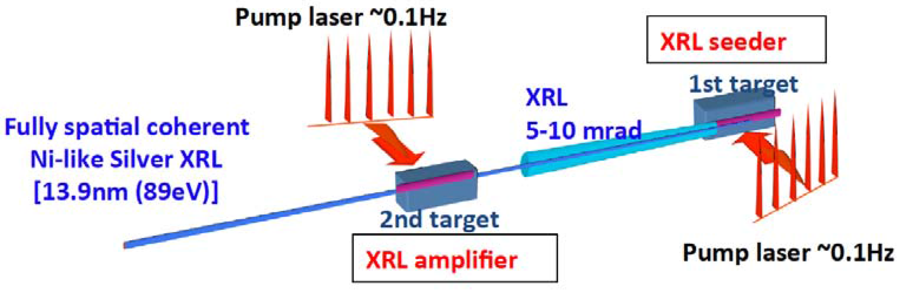
For delivering a plasma-base XRL pulse, a driver system, TOPAZ, is used, which is based on a Chirped Pulse Amplification(CPA) Nd:glass laser at KPSI. The TOPAZ system employs a zigzag slab-type amplifier chain, which allows us to operate with a repetition rate of 0.1 Hz because of the noticeable cooling efficiency of the zigzag slab amplifiers. A schematic of the TOPAZ is shown in Figure 10. It is routinely used for the generation of XRLs and the applied research of adding minor revisions to improve performance. In KPSI, we have demonstrated, for the first time, fully-spatial, coherent XRL beams at a wavelength of 13.9 nm by the oscillator-amplifier scheme. In the oscillator-amplifier configuration, the first gain medium functions as a soft X-ray oscillator, while the second gain medium functions as a soft X-ray amplifier. After optimization of the pumping condition for the soft X-ray amplifier on the second target, the high-quality XRL with an almost diffraction-limited divergence is generated. The typical parameters of the 13.9-nm laser include a beam divergence of better than 0.5 mrad, output of 200 nJ, and more than 109 photons/pulse. Figure 11 displays the beam pattern of the XRL beam. In the XRL system, the silver tape target is used for a repetition rate of 0.1 Hz. Figure 12 shows the tape target system, and the center position is irradiated by the pumping laser. More than 2000 shots are available by using a 50-m-long tape. Figure 13 shows the XRL beamlines for the applied research. The XRL beam is generated in the vacuum target chamber and is supplied to the downstream beam ports. There is a central beamline and some branches for the various applications. The applied experiments have been intensively promoted in the research field of materials science using single-shot X-ray imaging, XRL ablation, and nanoscale fabrication. In order to promote the area of applied research, we started upgrading the driving laser, and we will shift from a CPA:glass laser to a Ti:sapphire laser with the GRIP (Grazing Incidence Pumping) scheme. The 10-Hz, 20-TW CPA Ti:sapphire laser system consists of a regenerative amplifier system, pre-amplifier, and main amplifier. The laser pulse is amplified in the main amplifier of a 30-mm diameter Ti:sapphire crystal, and the amplified pulse energy is about 1.7 J at a repetition rate of 10 Hz. Conversely, we have also developed a Nd:YAG laser system using a master oscillator power amplifier platform. The maximum output energy is 4 J at a repetition rate of 50 Hz [12]. The Ti:sapphire laser system will be upgraded to the high-repetition-rate Nd:YAG laser system. Due to the high repetition rate, the expected applications include nanoscale fabrication and surface probes, such as a mask inspection for extreme-ultraviolet lithography.
4. High-Repetition-Rate, High-Peak-Power Laser Systems and Their Applications
In one of the four large experimental halls, high-repetition-rate laser systems have been developed and utilized for the investigation of the ultrafast excitation dynamics in atoms, molecules, and condensed matter. The layout of the laser system is illustrated in Figure 14.
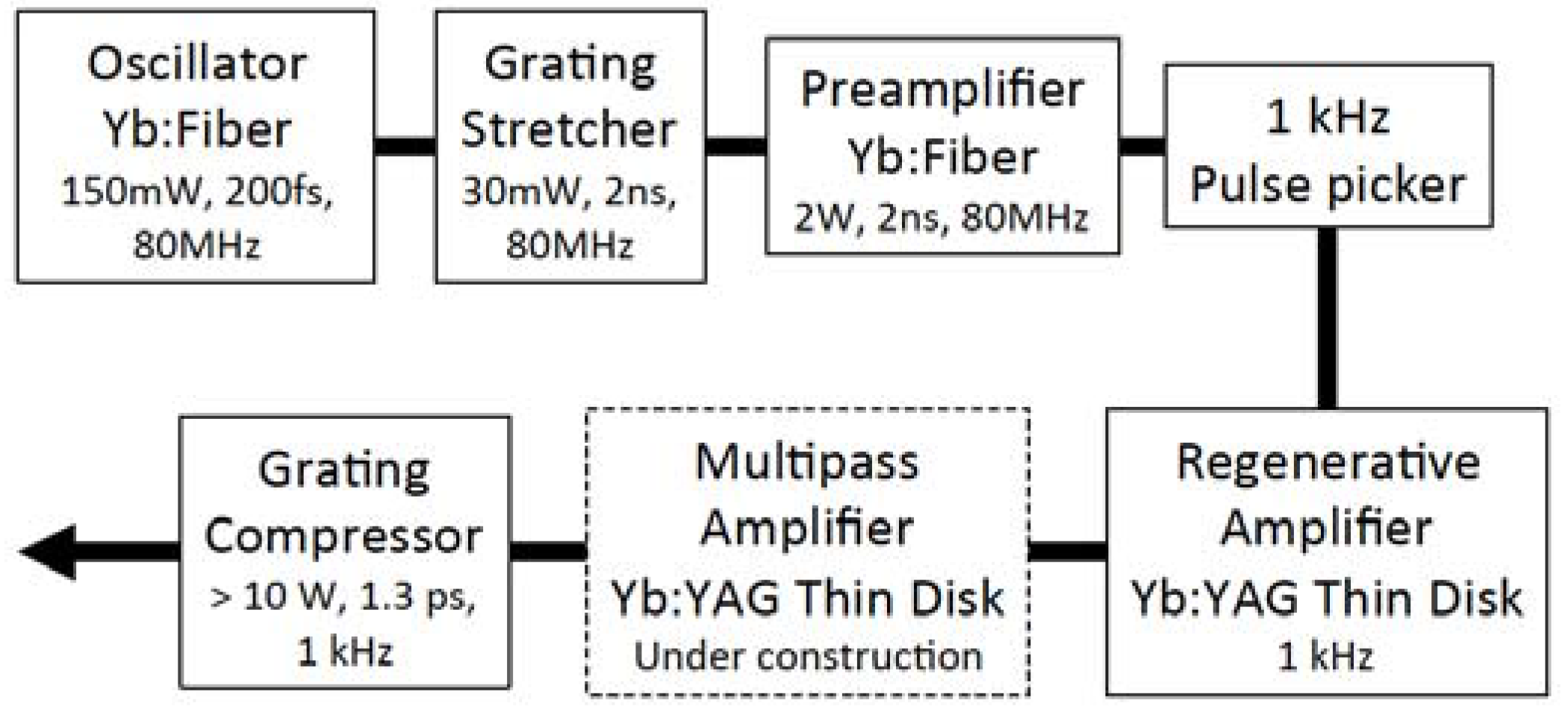
Aiming at strong THz pulse generation, a Yb:YAG thin-disk chirped-pulse-amplification laser system and QUADRA-T have been developed [13]. The system configuration of QUADRA-T is outlined in Figure 15. Currently, the regenerative amplification of this system operates at a repetition rate of 1 kHz with 10 mJ/pulse, a duration of 1.3 ps (FWHM), and a wavelength of 1.03 µm. We can achieve long-term stability within an RMS (Root Mean Square) of less than 1% for one-day operation when the output power is 10 mJ. If we make a sacrifice for long-term stability, a larger pulse energy of 17 mJ/pulse is achievable.
In order to achieve shorter pulse durations, a regenerative amplifier using a Yb:Y2O3 ceramic thin disk has been constructed. This system offers an output power of more than 2 mJ and a pulse duration of 0.9 ps (FWHM) [14].
For THz pulse generation, we adopt the optical rectification of the output from QUADRA-T in a Mg-doped stoichiometric LiNbO3 crystal. The method of tilting the pump pulse front is the solution to the large velocity mismatch between the near-infrared pump light and generated THz radiation in a crystal. In KPSI, a contact grating device with a Fabry-Perot resonator for effective THz radiation generation was designed and fabricated. It has already been demonstrated that this new device can efficiently generate THz radiation [15]. In comparison to the conventional method, which uses a diffraction grating and optical elements for image transportation to a LiNbO3 crystal, the contact grating device becomes significantly compact. The spatial quality also becomes homogeneous. This scheme is scalable to larger devices for generating stronger THz radiation.
Thin-disk amplification to generate high-power picosecond pulses is a key technology not only for strong THz pulse generation, but also for pumping OPCPA, which is now under construction at KPSI. Few-cycle, intense near-infrared pulses from OPCPA will be used for research on ultrafast dynamics in a variety of materials.
Two sets of Ti:sapphire CPA systems are also operated for the applied research. The specifications of these two systems are quite similar. The pulse energy is nearly 2 mJ, the pulse duration is 50 fs (FWHM), the repetition rate is 1 kHz, and the wavelength is 795 nm. One of the important research studies using these Ti:sapphire CPA systems is the investigation of the ultrafast ionization and dissociation dynamics of polyatomic molecules with photoelectron-photo ion coincidence momentum imaging apparatus [16]. The other is the terahertz application for monitoring photo-induced carriers in a semiconductor, such as Si [17]. The investigation of carrier dynamics in the THz regime leads to the development of unique devices in the THz regime: (i) high-efficiency etalons for THz radiation with an optical shutter [18], and (ii) a frequency upshifter by relativistic Doppler reflection from a photo-induced moving plasma front [19].
5. Summary
Three laser facilities at KPSI Kizu have been introduced. The XRL facility and QUADRA-T laser facility are now open for users, whereas J-KAREN-P has been also open since Fiscal Year (FY) 2017. We welcome your visit to KPSI Kizu and the use of these laser facilities for many attractive experiments. Especially, the J-KAREN-P facility will provide a high field of over 1022 W/cm2 with a high contrast at the focal point in the short-F chamber, and there are several interesting experiments with long interaction lengths at relativistic intensities in the long-f chamber.
Conflicts of Interest
The authors declare no conflict of interest.
References
- Kiriyama, H.; Mori, M.; Pirozhkov, A.S.; Ogura, K.; Sagisaka, A.; Kon, A.; Esirkepov, T.Z.; Hayashi, Y.; Kotaki, H.; Kanasaki, M.; et al. High-contrast, high-intensity petawatt-class laser and applications. IEEE J. Sel. Top. Quantum Electron. 2015, 21, 1601118. [Google Scholar] [CrossRef]
- Nishiuchi, M.; Sakaki, H.; Esirkepov, T.Z.; Nishio, K.; Pikuz, T.A.; Faenov, A.Y.; Skobelev, I.Y.; Orlandi, R.; Sako, H.; Pirozhkov, A.S.; et al. Acceleration of highly charged GeV Fe ions from a low-Z substrate by intense femtosecond lasers. Phys. Plasmas 2015, 22, 033107. [Google Scholar] [CrossRef]
- Nakamura, T.; Koga, J.K.; Esirkepov, T.Z.; Kando, M.; Korn, G.; Bulanov, S.V. High-Power Gamma-Ray Flash Generation in Ultraintense Laser-Plasma Interactions. Phys. Rev. Lett. 2012, 108, 195001. [Google Scholar] [CrossRef] [PubMed]
- Mori, M.; Kando, M.; Kotaki, H.; Hayashi, Y.; Bulanov, S.V.; Koga, J.; Kondo, K.; Pirozhkov, A.S.; Nishimura, H.; Nagashima, K. Condition of MeV Electron Bunch Generated from Argon Gas-Jet Target in the Self-Modulated Laser Wakefield Regime. J. Phys. Soc. Jpn. 2011, 80, 105001. [Google Scholar]
- Pirozhkov, A.S.; Kando, M.; Esirkepov, T.Z.; Gallegos, P.; Ahmed, H.; Ragozin, E.N.; Faenov, A.Y.; Pikuz, T.A.; Kawachi, T.; Sagisaka, A.; et al. Soft-X-Ray Harmonic Comb from Relativistic Electron Spikes. Phys. Rev. Lett. 2012, 108, 135004. [Google Scholar] [CrossRef] [PubMed]
- Pirozhkov, A.S.; Kando, M.; Esirkepov, T.Z.; Gallegos, P.; Ahmed, H.; Ragozin, E.N.; Faenov, A.Y.; Pikuz, T.A.; Kawachi, T.; Sagisaka, A.; et al. High order harmonics from relativistic electron spikes. New J. Phys. 2014, 16, 093003. [Google Scholar] [CrossRef]
- Kawase, K.; Kando, M.; Hayakawa, T.; Daito, I.; Kondo, S.; Homma, T.; Kameshima, T.; Kotaki, H.; Chen, L.M.; Fukuda, Y.; et al. Development of a bub-MeV X-ray source via Compton backscattering. Nucl. Inst. Methods Phys. Res. A 2011, 637, S141. [Google Scholar] [CrossRef]
- Kando, M.; Fukuda, Y.; Pirozhkov, A.S.; Ma, J.; Daito, I.; Chen, L.; Esirkepov, T.Z.; Ogura, K.; Homma, T.; Hayashi, Y.; et al. Demonstration of Laser-Frequency Upshift by Electron-Density Modulations in a Plasma Wakefield. Phys. Rev. Lett. 2007, 99, 135001. [Google Scholar] [CrossRef] [PubMed]
- Kando, M.; Pirozhkov, A.S.; Kawase, K.; Esirkepov, T.Z.; Fukuda, Y.; Kiriyama, H.; Okada, H.; Daito, I.; Kameshima, T.; Hayashi, Y.; et al. Enhancement of Photon Number Reflected by the Relativistic Flying Mirror. Phys. Rev. Lett. 2009, 103, 235003. [Google Scholar] [CrossRef] [PubMed]
- Kotaki, H.; Masuda, S.; Kando, M.; Koga, J.K.; Nakajima, K. Head-on injection of a high quality electron beam by the interaction of two pulses. Phys. Plasmas 2004, 11, 3296. [Google Scholar] [CrossRef]
- Kotaki, H.; Daito, I.; Kando, M.; Hayashi, Y.; Kawase, K.; Kameshima, T.; Fukuda, Y.; Homma, T.; Ma, J.; Chen, L.M.; et al. Electron Optical Injection with Head-On and Countercrossing Colliding Laser Pulses. Phys. Rev. Lett. 2009, 103, 194803. [Google Scholar] [CrossRef] [PubMed]
- Mikami, K.; Hasegawa, N.; Okada, H.; Kondo, S.; Nishikino, M.; Kawachi, T. Development of High-Repetition Rate and High-Pulse-Energy Nd:YAG MOPA Laser System. In Proceedings of the ICXRL2016, Nara, Japan, 22–27 May 2016. in press. [Google Scholar]
- Ochi, Y.; Nagashima, K.; Maruyama, M.; Tsubouchi, M.; Yoshida, F.; Kohno, N.; Mori, M.; Sugiyama, A. Yb:YAG thin-disk chirped pulse amplification laser system for intense terahertz pulse generation. Opt. Express 2015, 23, 15057–15064. [Google Scholar] [CrossRef] [PubMed]
- Maruyama, M.; Okada, H.; Ochi, Y.; Nagashima, K. Sub-picosecond regenerative amplifier of Yb-doped Y2O3 ceramic thin disk. Opt. Express 2016, 24, 1685–1692. [Google Scholar] [CrossRef] [PubMed]
- Tsubouchi, M.; Nagashima, K.; Yoshida, F.; Ochi, Y.; Maruyama, M. Contact grating device with Fabry-Perot resonator for effective terahertz light generation. Opt. Lett. 2014, 39, 5439–5442. [Google Scholar] [CrossRef] [PubMed]
- Hosaka, K.; Yokoyama, A.; Yamanouchi, K.; Itakura, R. Correlation between a photoelectron and a fragment ion in dissociative ionization of ethanol in intense near-infrared laser fields. J. Chem. Phys. 2013, 138, 204301:1–204301:9. [Google Scholar] [CrossRef] [PubMed]
- Tsubouchi, M.; Nagai, M.; Ohshima, Y. Terahertz tomography of a photo-induced carrier based on pump-probe spectroscopy using counterpropagation geometry. Opt. Lett. 2012, 37, 3528–3530. [Google Scholar] [CrossRef] [PubMed]
- Tsubouchi, M.; Kumada, T. Development of high efficiency etalons with an optical shutter for terahertz laser pulses. Opt. Express 2012, 20, 28500–28506. [Google Scholar] [CrossRef] [PubMed]
- Kohno, N.; Itakura, R.; Tsubouchi, M. Mechanism of relativistic Doppler reflection from a photoinduced moving plasma front studied by terahertz time-domain spectroscopy. Phys. Rev. B 2016, 94, 155205. [Google Scholar] [CrossRef]
Figure 1.
The Kansai Photon Science Institute (KPSI) Kizu site.
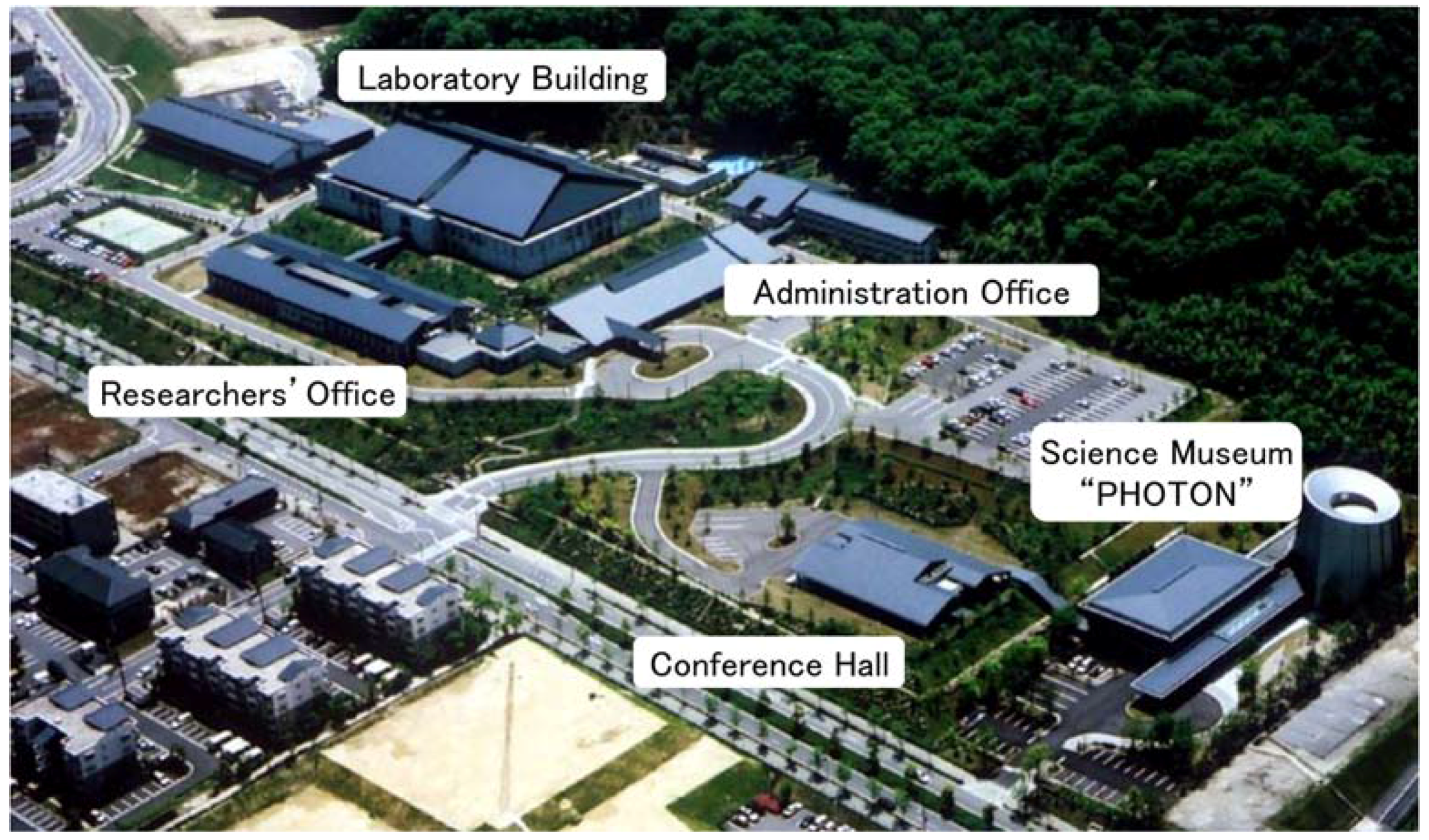
Figure 2.
Schematic of the top view of the laboratory building. Japan-Kansai Advanced Relativistic Engineering Petawatt: J-KAREN-P. Red arrow shows the propagation of amplified laser pulse from the optical amplifier hall to the interaction chamber hall.
Figure 2.
Schematic of the top view of the laboratory building. Japan-Kansai Advanced Relativistic Engineering Petawatt: J-KAREN-P. Red arrow shows the propagation of amplified laser pulse from the optical amplifier hall to the interaction chamber hall.

Figure 3.
Schematic of the top view of the interaction chamber hall for J-KAREN-P. NF: Near Field Monitor; FF: Far Field Monitor.
Figure 3.
Schematic of the top view of the interaction chamber hall for J-KAREN-P. NF: Near Field Monitor; FF: Far Field Monitor.

Figure 4.
Schematic of the J-KAREN-P laser system. AOPDF: Acousto-Optic Programmable Dispersive Filter; CPA: Chirped Pulse Amplification; OPCPA: Optical Parametric Chirped-Pulse Amplification.
Figure 4.
Schematic of the J-KAREN-P laser system. AOPDF: Acousto-Optic Programmable Dispersive Filter; CPA: Chirped Pulse Amplification; OPCPA: Optical Parametric Chirped-Pulse Amplification.

Figure 5.
Output energy from the booster amplifier 2 (BA2).
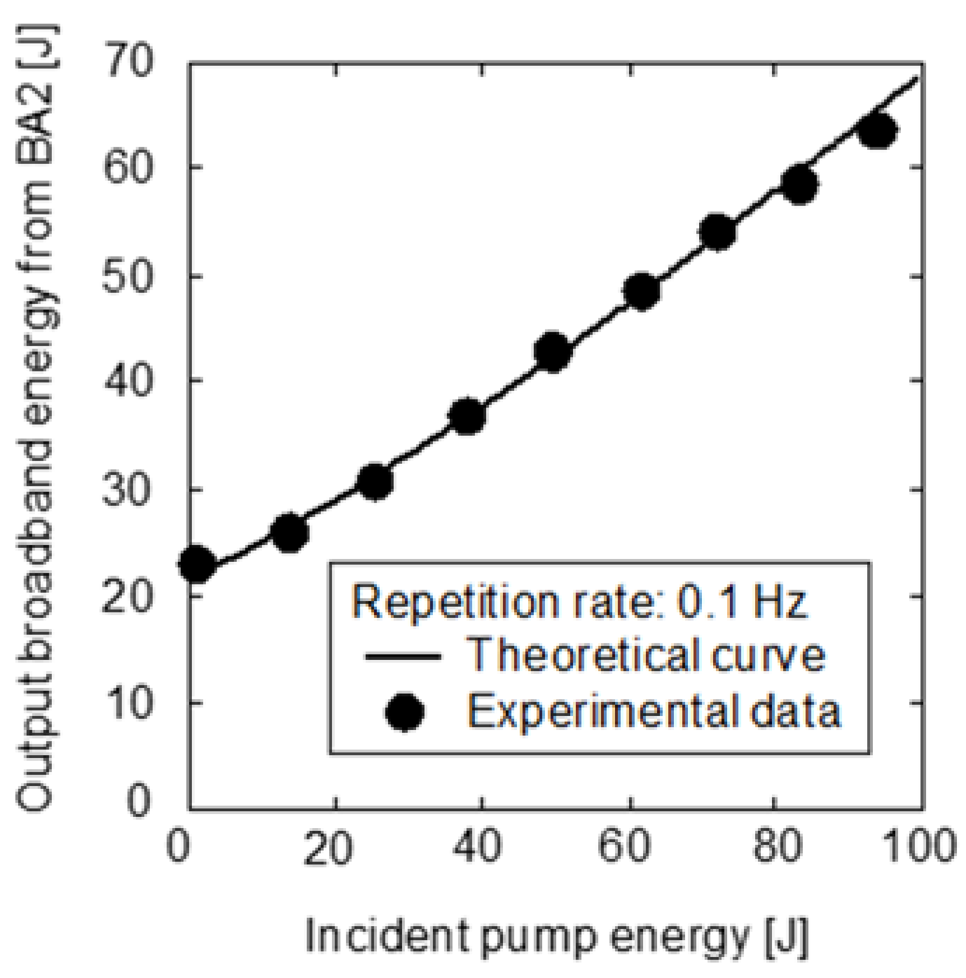
Figure 6.
Near-field intensity distribution of BA2 output.

Figure 7.
Inside view of the short-F chamber.
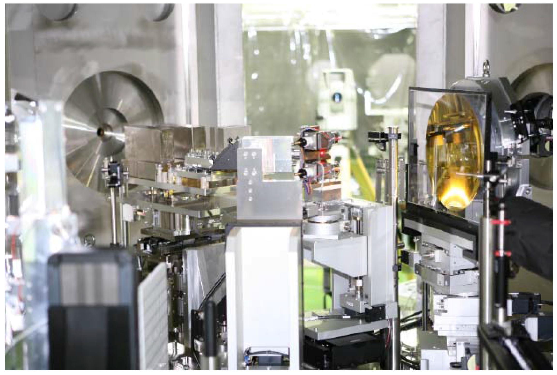
Figure 8.
Schematic of the ion acceleration experiment at the short-F chamber. Arrows represent the pass of the probe beam. Blue arrows are for side probe, and red arrows for rear side. RCF: Radiochromic Film; CR: Columbia resin 39 (CR-39); TOF: time of flight ion spectrometer; ESM: electron spectrometer; TP: Thomson parabola ion analyzer .

Figure 9.
Schematic of the electron acceleration experiment at the long-F chamber.
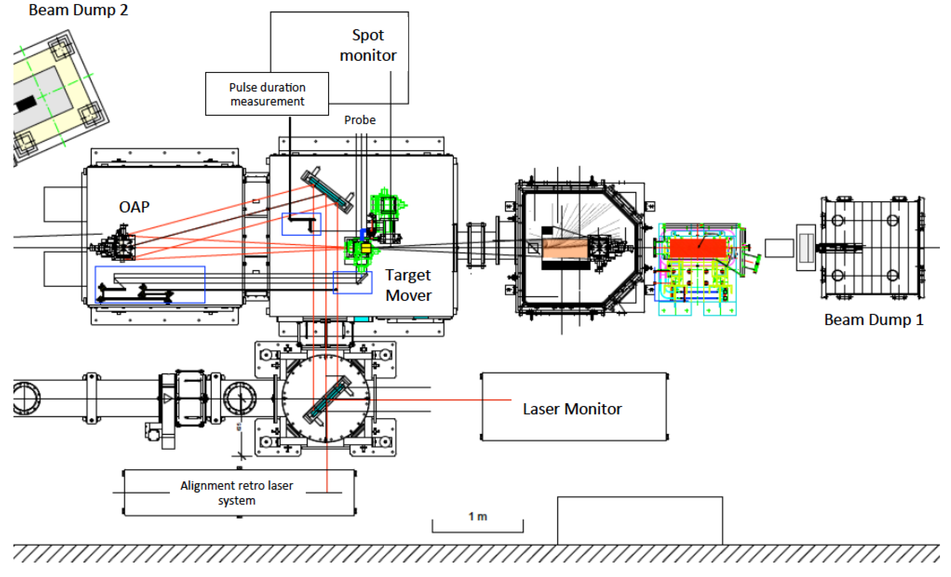
Figure 10.
Schematic of X-ray laser oscillator-amplifier configuration. XRL: X-Ray Laser.

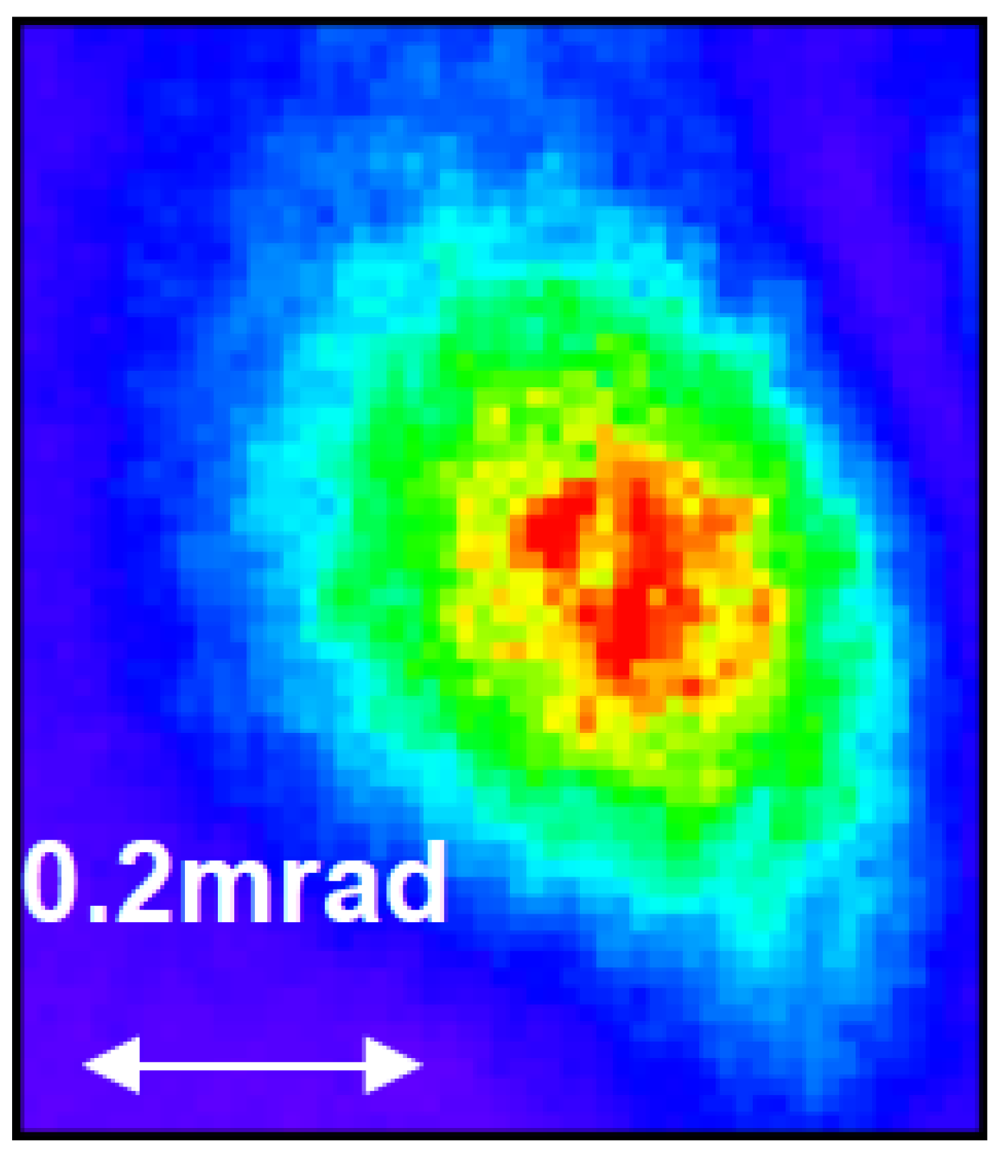
Figure 11.
Beam pattern of the XRL pulse. The pulse energy is 300–1000 nJ, and the beam divergence is less than 1 mrad.
Figure 11.
Beam pattern of the XRL pulse. The pulse energy is 300–1000 nJ, and the beam divergence is less than 1 mrad.

Figure 12.
Tape target system for generating XRL pulses.
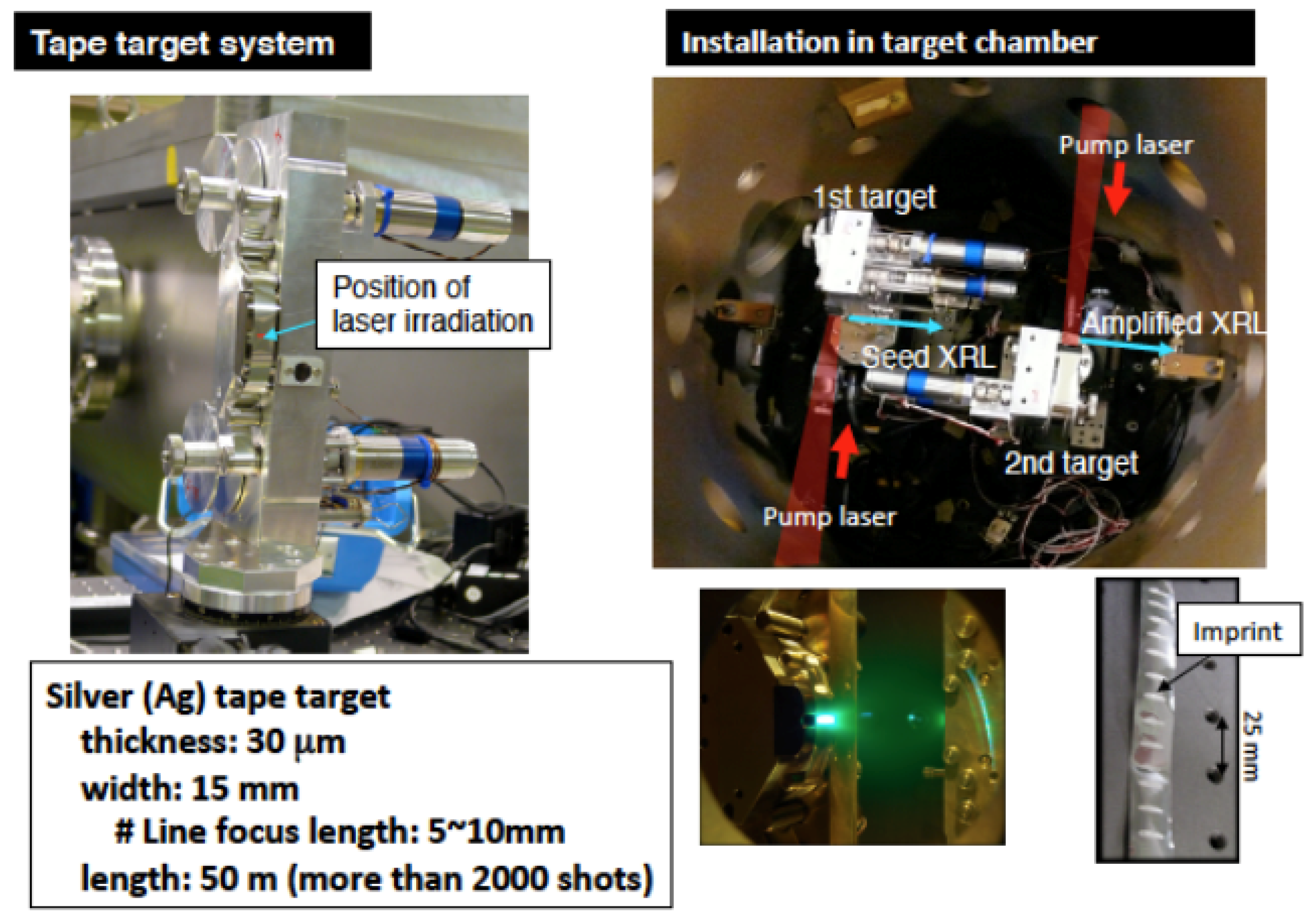
Figure 13.
XRL beamlines for applied research. Red arrow shows the pumping TOPAZ laser for generating XRL. Blue arrows the propagation of XRL for application chambers.
Figure 13.
XRL beamlines for applied research. Red arrow shows the pumping TOPAZ laser for generating XRL. Blue arrows the propagation of XRL for application chambers.

Figure 14.
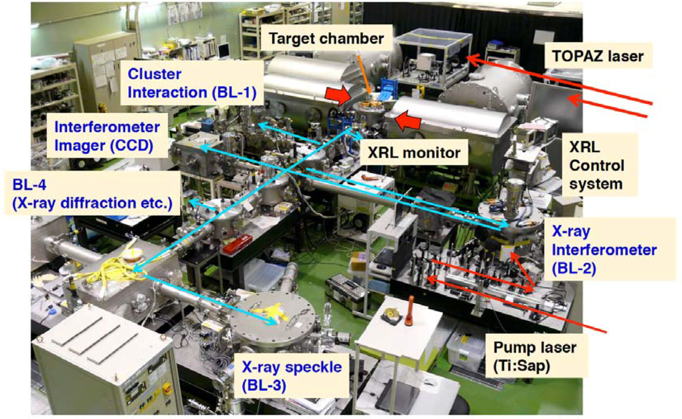
Experimental room for high-repetition-rate, high-peak-power laser systems.
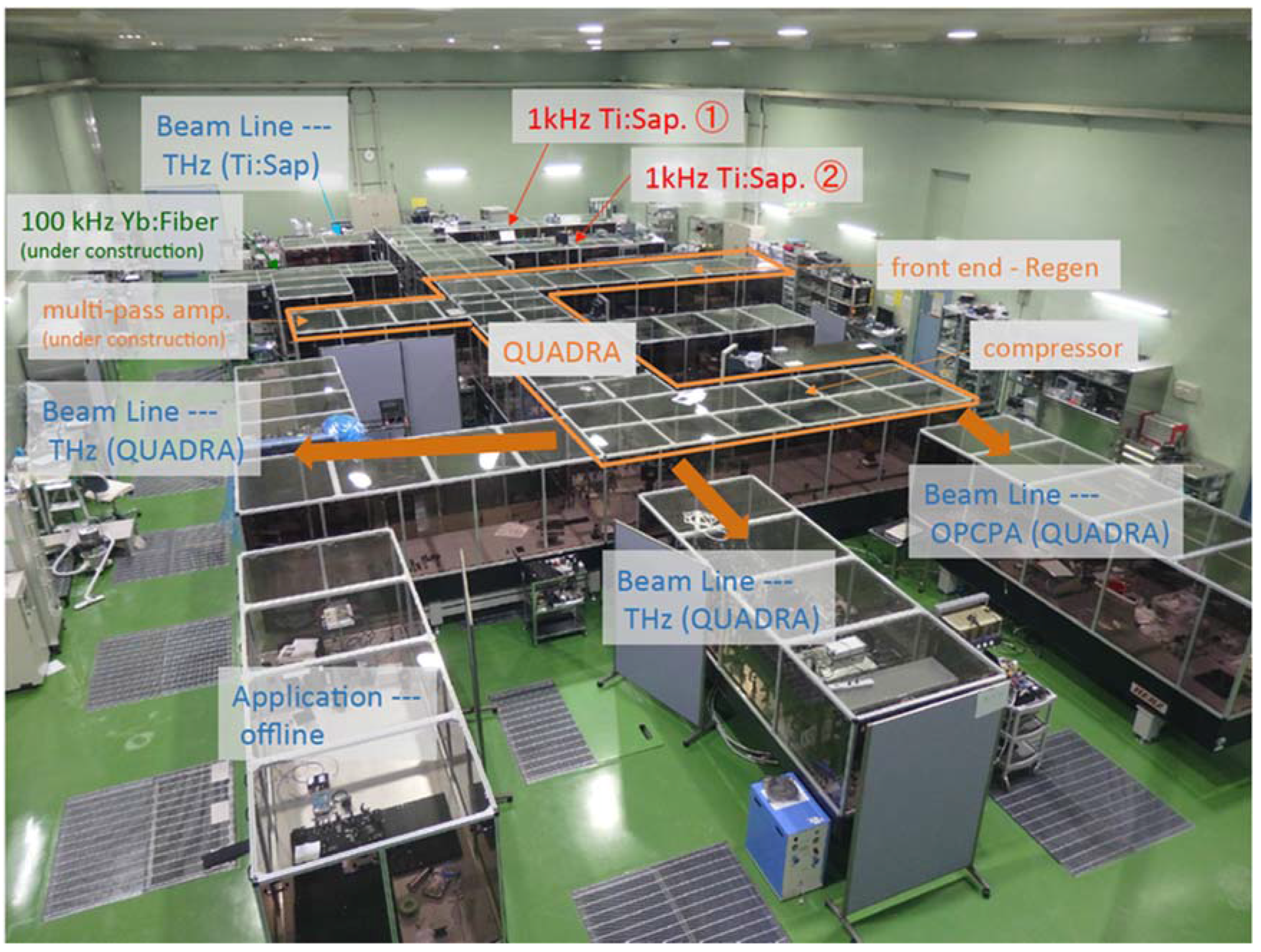
Figure 15.
Schematic of the QUADRA-T (Quality Ultra Advanced Radiation source Terahertz radiation) laser system.
Figure 15.
Schematic of the QUADRA-T (Quality Ultra Advanced Radiation source Terahertz radiation) laser system.

© 2017 by the authors. Licensee MDPI, Basel, Switzerland. This article is an open access article distributed under the terms and conditions of the Creative Commons Attribution (CC BY) license (http://creativecommons.org/licenses/by/4.0/).
Share and Cite
MDPI and ACS Style
Kondo, K.; Utsumi, W.; Kando, M.; Nishikino, M.; Itakura, R.; Kiriyama, H. High Power Laser Facilities at the Kansai Photon Science Institute. Quantum Beam Sci. 2017, 1, 7. https://doi.org/10.3390/qubs1010007
AMA Style
Kondo K, Utsumi W, Kando M, Nishikino M, Itakura R, Kiriyama H. High Power Laser Facilities at the Kansai Photon Science Institute. Quantum Beam Science. 2017; 1(1):7. https://doi.org/10.3390/qubs1010007
Chicago/Turabian StyleKondo, Kiminori, Wataru Utsumi, Masaki Kando, Masaharu Nishikino, Ryuji Itakura, and Hiromitsu Kiriyama. 2017. "High Power Laser Facilities at the Kansai Photon Science Institute" Quantum Beam Science 1, no. 1: 7. https://doi.org/10.3390/qubs1010007