A Work Area Visualization by Multi-View Camera-Based Diminished Reality


Department of Information and Computer Science, Keio University, Yokohama 223-8521, Japan
*
Author to whom correspondence should be addressed.
†
Current address: 3-14-1 Hiyoshi Kohoku-ku, Yokohama 223-8522, Japan.
‡
The authors contributed equally to this work.
Multimodal Technol. Interact. 2017, 1(3), 18; https://doi.org/10.3390/mti1030018
Submission received: 15 July 2017
/
Revised: 12 August 2017
/
Accepted: 31 August 2017
/
Published: 5 September 2017
(This article belongs to the Special Issue Recent Advances in Augmented Reality)
Abstract
:Hand-held tools are indispensable for efficient manual working in fields ranging from woodworking to surgery. In this paper, we present a diminished reality (DR) method to visualize areas occluded by hands and tools in various hand-working scenarios. We propose a redesigned existing arbitrary viewpoint image generation method for DR applications as a core DR background rendering to recover views without undesirable objects. We conducted quantitative and qualitative experiments using real data to validate the performance of the proposed method. The experimental results showed that our method runs in real-time (40.1 fps) and surpasses conventional methods (including image inpainting-based and geometry-based approaches) in terms of image similarity measures.
1. Introduction
Various hand-held tools are used for efficient manual operations in fields such as woodworking, cooking, and surgery. This benefit comes with visual occlusion of the working area, however, because these devices tend to be large due to their driving parts, joints, batteries, etc. For example, readers may have experienced situations where a gripped electric drill shields the work target, thus making observation of the work target directly from the front impossible. One classical solution to this problem is to observe the working area from another viewpoint through mirrors or cameras. But this method requires cumbersome mental viewpoint conversions from the different view to the eye view; in the case of mirrors, mirror-image conversion is also necessary. To overcome this problem, computer-aided viewpoint conversions may be substituted for mental viewpoints.
Augmented reality (AR) [1,2] allows the information of the hidden background to be directly overlaid to the real environment, but the information is described in indirect forms such as digital annotations. Contrary to this concept of augmentation, visualization technology for making things less noticeable or invisible is called diminished reality (DR) [3]. Some reports have found that effective visual information reduction improves specific manual task performances [4,5]. DR estimates the occluded areas using multi-viewpoint cameras partially observing the areas. Therefore, to visualize the changing hidden work target by removing the occluding objects, we need to surround the target area with multi-view cameras to increase the chances of observing the background with any of the installed cameras. However, existing DR methods based on multi-view geometry utilize depth searching in overlapped regions of the each view and thus have difficulty in observing the scene from a variety of direction [6,7]. Such approaches, in principle, require a number of cameras, although the increase in the number of cameras increases computational costs.
To avoid this trade-off between the number of cameras and visualization quality in DR-based work area display, we propose a low-cost background view rendering algorithm based on multi-view images. The proposed real-time rendering algorithm is a redesign of the existing arbitrary viewpoint image generation method for DR applications, which results in a DR system that can handle view-dependent properties in rendering results. This has not been achieved in any real-time observation-based DR approaches to date.
Our contributions in this paper are summarized as follows:
- We present a multi-view-based work area visualization method that solves occlusion problems in hand-work scenarios.
- To achieve this, we propose to redesign an existing arbitrary viewpoint image generation method [8] as a core DR background rendering to recover views without undesirable objects (e.g., hands and tools).
- We conducted quantitative and qualitative experiments using real data to validate the performance of the proposed method.
2. Related Work
In this section, we introduce various DR methods (including the state of the art) and discuss differences with our proposed method. DR methods can be roughly divided into methods that can handle dynamic and static environments. These differences come from the acquisition timing of the background image resources. DR that utilizes background pre-capturing can secure a sufficient number of viewpoints for background recovery (as much as time and memory allow), while DR of online capturing needs to somehow compensate for limited resources in the time between frames. The proposed DR system aims to sequentially visualize changing work areas. The proposed method thus is classified as a DR method for dynamic backgrounds. Table 1 summarizes the characteristics of existing DR methods and the proposed method.
2.1. DR for Static Background
Zokai et al. removed factory piping in the current view placed between two stationary cameras observing the background [6]. In this framework, a point on a light ray extended toward each pixel from the view center is projected onto the other two cameras, and the similarity of the projected point pairs is calculated. This operation is executed according to the depth; the depth and color of the point at the highest score is considered to be the depth and color of the hidden background in the current view. In principle, this method seems likely to be applicable to dynamic scenes, but this has yet to be demonstrated. Herling et al. [9] and Kawai et al. [10] implemented a patch-based inpainting method to estimate background pixels based on the pixels based on pixels in the current view. In this case, because the background is not actually observed, a literal plausible background image is presented. Therefore, the background must be static. Since this inpainting method takes several seconds to complete the process, the inpainting process is separated from the other processes using a multithread technique. When the object to be diminished moves, it takes more time to complete the inpainting processing. Li et al. removed a person in a video [11]; the authors selected a background to cover the person with a homography-warped image fetched from the Internet based on GPS information. Because the Internet photos were calibrated beforehand, one image was selected and switched if the view became close to a different image.
In contrast to the methods introduced thus far, the proposed method sequentially updates the background resources of video streams with several multi-view cameras surrounding the environment. The most relevant approach in terms of the rendering framework is a method proposed by Cosco et al. [4], who removed a visually obstructive haptic device using their visuo-haptic system. Assuming the background was static, they manually created scene polygons and captured the scene from various viewpoints before placing the haptic device. They used the images as inputs for a simplified unstructured lumigraph rendering (ULR) [8] to recover the currently hidden area. We instead use a rangefinder and multiple color sensors to obtain the background’s geometric and appearance changes, respectively, in an automatic manner. We also need to factor in objects to be removed that appear in the background resources, which do not appear in Cosco et al.’s pre-captured background images.
2.2. DR for Dynamic Background
Jarusirisaward et al. generated arbitrary viewpoint images without the object to be removed by defining a scene reconstruction volume of plane-sweep algorithm so as not to include the removal object [7]. Assuming Lambertian backgrounds, this depth-search-based method involves numerous similarity measurements to estimate depths and colors, thus making the method’s real-time property poor. Barnum et al. proposed a method to see through a scene behind a wall by installing a camera behind the wall [12]. Barnum et al. method divides the background into static and dynamic planes, which are then projected onto the current viewpoint. Assuming the background consists of two planes (e.g., facades and a pedestrian), this method does not require time-consuming depth searching for background estimation. Meerits and Saito enabled DR processing in a 3D dynamic background using an RGB-D sensor to avoid the depth searching [13]. The number of viewpoints for background observation is limited, however, because of practical issues such as mutual infrared interference of the RGB-D sensors and the existence of unrecovered pixels due to an insufficient number of viewpoints need to be filled using inpainting processing. In this case, it becomes difficult to perform real-time processing [13].
The challenges of this study are twofold: (1) to achieve DR in a 3D dynamic scene using the real-time observation-type DR methods described above; and (2) to simultaneously develop a rendering framework that will preserve the view-dependent properties derived from multi-viewpoint observations. To the best of our knowledge, DR methods that have these two properties have yet to be achieved.
3. Method
3.1. Overview
Given calibrated multi-viewpoint cameras surrounding the working environment (Section 3.2), our goal is to remove a tool held in the worker’s hand in the worker’s view C, as shown in Figure 1. Figure 2 shows our proposed pipeline. To achieve this, we redesign the camera blending fields (CBFs) of Buehler et al.’s ULR [8], which is a generalized form of free-viewpoint image generation method that uses unstructured cameras. Our DR system first captures multiple color images and a depth image and starts calculating CBF (Section 3.3), surface extraction (Section 3.4), region of interest detection (Section 3.5), and finally view synthesis (Section 3.6). The following sections describe the redesigned CBF to view synthesis using the CBF for DR rendering.
3.2. Multi-View Camera Calibration
We first calibrate a single RGB-D camera and multiple conventional cameras to obtain the intrinsic and extrinsic parameters of each camera. Because the reference points of the following CBF calculation (Section 3.3) are built using the depth image , all cameras are aligned regarding the RGB-D camera. First, we perform feature point matching between the images to obtain 2D-2D correspondences in images . Since one of the images is incorporated with a depth image , we obtain 3D-2D correspondences of all cameras . Then, we perform bundle adjustment [16] with the 3D-2D correspondences and camera poses calculated by solving the perspective-n-point problem [17] as the initial value.
3.3. Camera Blending Field with Penalty Points
A CBF is a map of weights or ratios to blend M color cameras in a worker’s view C (i.e., blending weights of data cameras in [8]). A CBF is calculated based on positions of the user view C and data cameras , surface points , and penalty points . Here, surface points and penalty points refer to as a set of points representing the background surface and representative points of the object to be diminished respectively (See Figure 1). In the proposed method, penalty weights are given to the data cameras including light rays that closely pass through penalty points ; in other words, light rays detour around the points. We assume that data cameras surround a target work area to remove an occluder (an electric drill shown in Figure 1) in a generated background image. Given poses and projection matrices of the data cameras, the blending weights of each data camera to each 3D point are calculated as follows.
where is a function that returns 1 when the 2D point exists within the image plane and otherwise 0. and are calculated as follows.
where , , and is a normalized vector from a virtual camera C, , and to , respectively. and are user-controllable values to determine effects of and respectively.
3.4. Surface Extraction
We extract surface points and penalty points from using depth frames. Because we receive only one depth map per frame, we transform it to the worker’s view and separate that to foreground and background depth maps. First, the input depth map is back-projected as a 3D point cloud. Then, the surface points are transformed to the worker’s viewpoint C, thus yielding a depth map from the worker’s perspective. Although some regions are missing or cannot be observed from the RGB-D camera, they can be filled in with surface splatting [18] and the past depth frames.
Depth map frames are updated using the following equation at every frame.
where is an arbitrary value and is a previous depth frame calculated by this equation. Therefore, we can obtain a temporally smoothed depth map by setting and at the initial and following frames, respectively. To do this, we assume that, at least in the first two frames of each data camera , objects to be diminished do not appear in the field of view.
After this process, the depth map of weighted average is separated into foreground and background depth maps based on the following calculation.
where t is an arbitrary tolerance value and is a mask image representing the foreground and background .
Note that the foreground and background depth maps are updated using Equation (7) separately. Finally, we collect 2D points at regular intervals from the worker’s view and back-project them to calculate 3D points based on the background depth map.
3.5. Region of Interest Detection
The raw mask image of objects of interest does not perfectly extract the shape of the region of interest (ROI) due to the erratic depth measure of the RGB-D sensor [19]. Therefore, we detect ellipses [20] to extract rough shapes of the objects of interest with smooth borders and update the mask . The detected center points of the ellipses are then back-projected based on the foreground depth map to be used as penalty points .
3.6. View Synthesis
3D points comprise triangle meshes known as geometric proxy [8]. These triangle meshes can be an approximation of a surface of a background or focal plane. Based on the calculated CBF, images of n most-weighted data cameras are projected onto each mesh using projective texture mapping; they are then blended using an alpha blending scheme [21].
Given an ROI frame (Section 3.5), projected 3D points can be distinguished to ones in the ROI or ones out of the ROI; points in each triangle are also identifiable. Therefore, we can categorize a triangle into one of three types: (1) all points in ROI, (2) all points out of ROI, and (3) at least one point in ROI. The first type of triangle is rendered in a straightforward manner; the second type is discarded (i.e., it is not rendered). For the third type, setting the weight for points out of ROI to zero, we obtain a gradual alpha blend at the borders of ROI.
4. Experiments
4.1. Overview and Setup
In this section, we describe two experiments to demonstrate the effectiveness and performance of our method. In the first experiment, we present video results of existing DR methods and the proposed method for comparison (Section 4.2). In the second experiment, we evaluated the proposed method in a quantitative comparison using a similarity measure (Section 4.3).
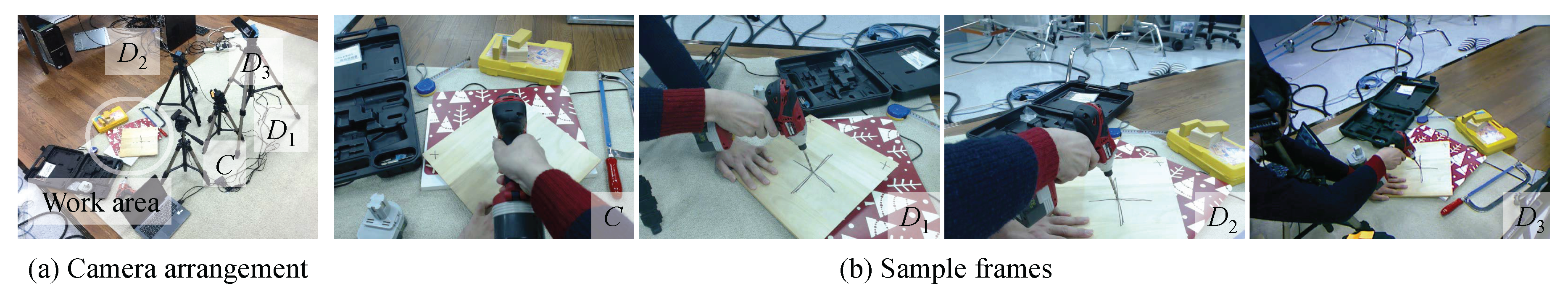
In all experiments, we used a Microsoft Kinect sensor and three USB cameras (640 × 480 resolution) to record frames showing non-planar work areas; and are both set to 1.0. We used an electric drill/screw as a hand-held device to be diminished. The proposed system was implemented on a Windows 10 64-bit laptop with an Intel Core i7-6567U 3.30 GHz CPU, Intel Iris Graphics 550 GPU, and 16.0 GB memory. The CBF calculation (Section 3.3) and view synthesis based on the CBF (Section 3.6) was implemented on CPU and GPU, respectively. The system was implemented using C++ and OpenGL shading language 3.3.
Because the drawing of each triangle polygon on the estimated background surface in Section 3.6 can be handled independently, the drawing may be processed at high speed via parallel processing. The proposed method uses a geometry shader scheme in OpenGL to duplicate one triangle into three in order to blend them in one draw call, while general image-based rendering performs three draw calls for one triangle to blend three vertices’ weights (Related discussions can be found in [22]).
4.2. Video Performance Evaluation
We present video results of the proposed method (A supplemental video is presented) and conventional DR methods for visual comparison in a DR scenario to show that our method works in real-time to remove an object of interest in a dynamic scene. Here, we discuss image quality of each DR method. Figure 3 shows our setup in this experiment. For comparison, we selected Photoshop Content-Aware Fill and surface splatting [18] as the inpainting and geometry-based approaches, respectively. To apply the inpainting to the videos, we created mask frames in a manner described in Section 3.5 and filled in the ROI with the inpainted results. We used this mask sequence for the other two methods. For surface splatting, we used the Kinect sensor and a USB camera of the worker’s perspective. That is, the Kinect point clouds were transformed to the worker’s view and rendered as surfels [18] in the ROI. We hereby refer to the frame-by-frame Photoshop Content-Aware Fill and the surface splatting to PS and SS, respectively.
Figure 4 shows several frames picked up from the video result. In the video, the user held the electric drill with the right hand and used the left hand to move the wood board for convenience (i.e., the scene is dynamic). A cross mark painted on the wooden board was almost lost using the PS method, while it was visible when using the other methods. Although SS generated plausible backgrounds, a few regions appeared black because of unobservable pixels from the Kinect, similarly to [13]. In contrast, our method filled in these regions due to depth compensation (discussed in Section 3.4) and the multi-view-based rendering scheme discussed in Section 3.3 and Section 3.6. The reproduced background colors were mediated due to the multi-view image synthesis used in our method, although color inconsistency between the ROI and the other region was detectable in SS. Consequently, our method presents fine textures and colors in the results, except for the blurs caused by the multi-view synthesis. The frame rate of the proposed method was around 40.1 fps, meaning the proposed method works in real-time.
4.3. Similarity Measure
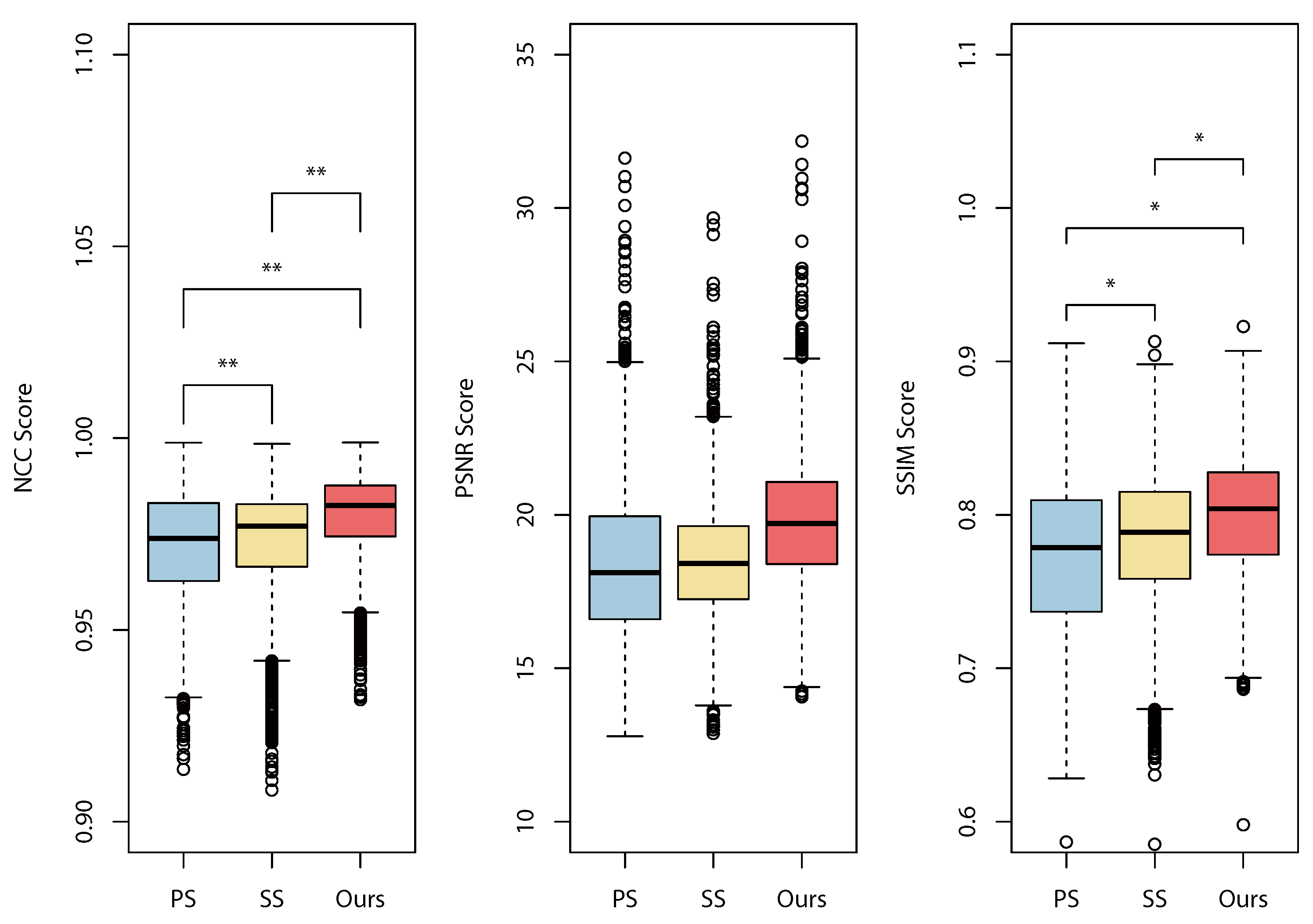
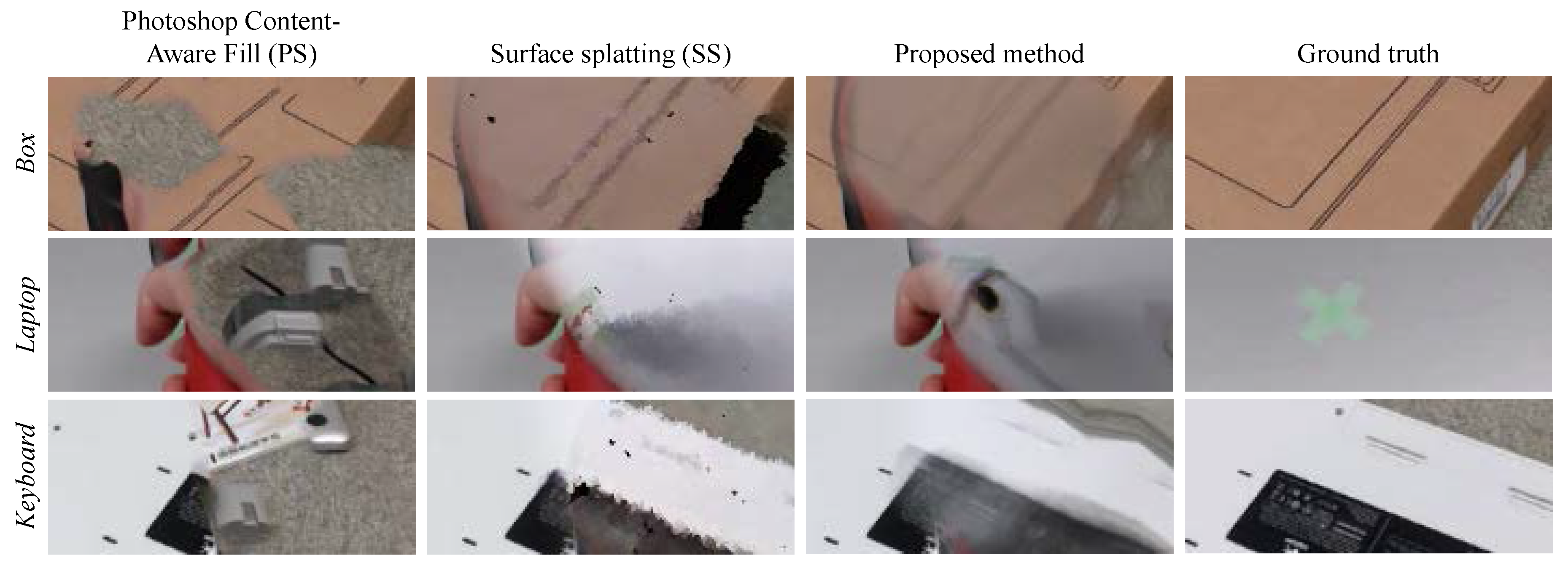
Because it is difficult to obtain image sequence pairs of inputs and ground truth (since the background is not observable during recordings), we obtained still image results using the proposed method and those provided from conventional methods to evaluate the images in normalized cross correlation (NCC), peak signal to noise ratio (PSNR), and structural similarity (SSIM) measure [23]. For comparison, we used the same methods used in the previous experiment. To measure the similarities, we recorded image pairs of the input multi-view images and corresponding ground truth images . We then obtained DR results using the three DR methods in three scenes: Box, Laptop, and Keyboards shown in Figure 5 and Figure 6.
We first built and captured a scene as a ground truth image. We then started to record multi-view images and waved a hand holding an electric drill to be removed in front of the cameras. We repeated this recording process several times per scene by changing the backgrounds’ arrangements of objects. We used such image pairs if ROI frames were valid. We obtained 5225 resulting image pairs. Finally, we calculated the NCC, PSNR, and SSIM of and , which we refer to as , , and , respectively.
In this experiment, we formulated two hypotheses:
H1.
In all similarity measures, our methods exceed the other methods.
H2.
The order of the measurements are PS < SS < Ours.
is based on the facts that PS does not observe the actual backgrounds, SS does not use multi-view images, and our method observes the actual background with multi-view cameras (i.e., the proposed method can handle richer image resources compared to the others).
Figure 7 and Table 2 show the statistical DR results of the NCC, PSNR, and SSIM evaluations. An analysis of variance (ANOVA) (Tukey-Kramer test) showed significant differences between all combinations of PS, SS, and our method in NCC and SSIM. From the results, and hold in NCC and SSIM. We did not observe a significance in PSNR; we considered that this was due to the characteristics of PSNR, which provides low scores to DR results, even for small misalignments, and the scores vary widely. The mean values in PSNR, however, showed a similar improvement to those in NCC and SSIM. These results, and the apparent quality shown in Figure 5 and Figure 6, provide a similar impression.
Figure 5 shows original user view images, mask images, PS images, SS images, our results, and corresponding ground truth images from each scene. Figure 6 shows close-up views of the green rectangles with dashed lines shown in Figure 5. PS filled much of the ROI with the texture of the carpet, which is a measured texture in the original view; the overall results are an unnatural patchwork of DR images. SS generates plausible results, but in the Box scene, for example, a side of the box has completely disappeared, since it is not visible from the Kinect. In contrast, the proposed method has no such vacant region. Because our method attempts to use pixels from the closest views, based on the algorithm presented in Section 3.3, the metrical surfaces of the background objects appear natural and without unnecessary speculars in the Laptop scene. However, due to the multiple image blending, our method tends to generate blurred image as shown in the Keyboard scene.
5. Discussion
5.1. Geometric Issues
In terms of the DR image quality, our method relies on the quality of the surface estimation because the surfaces are where the data images are projected; in other words, they are digitally focused [24]. A multiple RGB-D camera system is thus one possible extension, although using multiple RGB-D cameras would create interference problems [25]. Compared to extending the system configuration, we could use a partial depth-searching approach for the limited region to be reconstructed to reduce computational costs.
5.2. Representation and Interface
Based on a rough survey on impressions of our DR results, respondents reported both positive and negative impressions. The positive opinions were nearly the same as the advantages described in Section 4. The negative opinions were mainly related to the DR representations. For example, when the electric device the user held was removed completely, the user became confused, since the user’s hand and tool were invisible. Buchmann et al. [5] discussed similar results; their basic solution was to use semi-transparent representation, which is the de facto standard for representing an object to be removed as semi-transparent (for example, the AR X-ray [28,29] and See-through Vision [12,30]).
We believe, however, that such rendering methods do not fully solve the problem mentioned above. In our case, the tip of the drill (and whether or not it touches the surface) is the most important information to the user. Even though AR X-ray and See-through Vision can show the backgrounds and the tool at the same time, these methods cannot recover the tip of the drill in the user’s view. As such, the DR representation issue remains as future work.
6. Conclusions
In this paper, we presented a DR method based on multiple viewpoint cameras to visualize occluded work areas in manual work scenarios. Our DR rendering scheme is a redesign of unstructured lumigraph rendering for DR applications and runs in real time, thus preserving view-dependent properties. Quantitative evaluations and qualitative comparisons supported the fact that our method surpasses the conventional methods in terms of image similarity measures. We also discussed limitations and further improvements to be implemented in the near future.
Supplementary Materials
The following are available online at https://www.mdpi.com/2414-4088/1/3/18/s1. We provide a supplemental video corresponding to the results shown in Figure 4.
Acknowledgments
This work was supported in part by a Grant-in-Aid from the Japan Society for the Promotion of Science Fellows Grant Number 16J05114.
Author Contributions
S.M. designed and implemented the proposed method and organized this paper; M.M. partially implemented the proposed method and performed the experiments; H.S. designed the experiments and helped to draft the manuscript.
Conflicts of Interest
The authors declare no conflict of interest.
References
- Azuma, R.T. A survey of augmented reality. Presence Teleoper. Virtual Environ. 1997, 6, 355–385. [Google Scholar] [CrossRef]
- Azuma, R.T. Recent advances in augmented reality. IEEE Comput. Graph. Appl. 2001, 21, 34–47. [Google Scholar] [CrossRef]
- Mori, S.; Ikeda, S.; Saito, H. A survey of diminished reality: Techniques for visually concealing, eliminating, and seeing through real objects. IPSJ Trans. Comput. Vision Appl. 2017, 9. [Google Scholar] [CrossRef]
- Cosco, F.; Garre, C.; Bruno, F.; Muzzupappa, M.; Otaduy, M.A. Visuo-haptic mixed reality with unobstructed tool-hand integration. IEEE Trans. Vis. Comput. Graph. 2013, 19, 159–172. [Google Scholar] [CrossRef] [PubMed]
- Buchmann, V.; Nilsen, T.; Billinghurst, M. Interaction with partially transparent hands and objects. In Proceedings of the Sixth Australasian User Interface Conference, Newcastle, Australia, 30 January–3 February 2005; Volume 40, pp. 17–20. [Google Scholar]
- Zokai, S.; Esteve, J.; Genc, Y.; Navab, N. Multiview paraperspective projection model for diminished reality. In Proceedings of the International Symposium on Mixed and Augmented Reality (ISMAR), Tokyo, Japan, 7–10 October 2003; pp. 217–226. [Google Scholar]
- Jarusirisawad, S.; Hosokawa, T.; Saito, H. Diminished reality using plane-sweep algorithm with weakly-calibrated cameras. Prog. Inform. 2010, 7, 11–20. [Google Scholar] [CrossRef]
- Buehler, C.; Bosse, M.; McMillan, L.; Gortler, S.; Cohen, M. Unstructured lumigraph rendering. In Proceedings of the Special Interest Group on Computer Graphics and Interactive Techniques (SIGGRAPH), Los Angeles, CA, USA, 31 July–4 August 2001; pp. 425–432. [Google Scholar]
- Kawai, N.; Sato, T.; Yokoya, N. Diminished reality based on image inpainting considering background geometry. IEEE Trans. Vis. Comput. Graph. 2016, 22, 1236–1247. [Google Scholar] [CrossRef] [PubMed]
- Herling, J.; Broll, W. High-Quality Real-Time Video Inpaintingwith PixMix. IEEE Trans. Vis. Comput. Graph. 2014, 20, 866–879. [Google Scholar] [CrossRef] [PubMed]
- Li, Z.; Wang, Y.; Guo, J.; Cheong, F.L.; Zhou, Z.S. Diminished reality using appearance and 3D geometry of Internet photo collections. In Proceedings of the International Symposium on Mixed and Augmented Reality (ISMAR), Adelaide, Australia, 1–4 October 2013; pp. 11–19. [Google Scholar]
- Barnum, P.; Sheikh, Y.; Datta, A.; Kanade, T. Dynamic seethroughs: Synthesizing hidden views of moving objects. In Proceedings of the International Symposium on Mixed and Augmented Reality (ISMAR), Orlando, FL, USA, 19–22 October 2009; pp. 111–114. [Google Scholar]
- Meerits, S.; Saito, H. Real-time diminished reality for dynamic scenes. In Proceedings of the International Workshop on Diminished Reality, Fukuoka, Japan, 29 September–3 October 2015; pp. 53–59. [Google Scholar]
- Klein, G.; Murray, D. Parallel tracking and mapping for small AR workspaces. In Proceedings of the IEEE and ACM International Symposium on Mixed and Augmented Reality (ISMAR 2007), Nara, Japan, 13–16 November 2007; pp. 225–234. [Google Scholar]
- Kato, H.; Billinghurst, M. Marker tracking and hmd calibration for a video-based augmented reality conferencing system. In Proceedings of the IEEE and ACM International Workshop on Augmented Reality (IWAR), San Francisco, CA, USA, 20–21 October 1999; pp. 85–94. [Google Scholar]
- Lourakis, M.I.A.; Argyros, A.A. SBA: A software package for generic sparse bundle adjustment. Trans. Math. Softw. 2009, 36. [Google Scholar] [CrossRef]
- Lepetit, V.; Moreno-Noguer, F.; Fua, P. EPnP: An accurate O(n) solution to the PnP problem. Int. J. Comput. Vis. 2009, 81, 155–166. [Google Scholar] [CrossRef] [Green Version]
- Zwicker, M.; Pfister, H.; Baar, J.V.; Gross, M. Surface splatting. In Proceedings of the Special Interest Group on Computer Graphics and Interactive Techniques (SIGGRAPH), Los Angeles, CA, USA, 31 July–4 August 2001; pp. 371–378. [Google Scholar]
- Handa, A.; Whelan, T.; McDonald, J.; Davison, A.J. A benchmark for RGB-D visual odometry, 3D reconstruction and SLAM. In Proceedings of the IEEE International Conference on Robotics and Automation (ICRA), Hong Kong, China, 31 May–17 June 2014; pp. 1524–1531. [Google Scholar]
- Fitzgibbon, A.W.; Fisher, R.B. A buyer’s guide to conic fitting. In Proceedings of the British Machine Vision Conference (BMVC), Beimingham, UK, 11–14 September 1995; pp. 513–522. [Google Scholar]
- Debevec, P.; Borshukov, G.; Yu, Y. Efficient view-dependent image-based rendering with projective texture-mapping. In Proceedings of the Eurographics Rendering Workshop, Vienna, Austria, 29 June–1 July 1998; pp. 85–92. [Google Scholar]
- Davis, A.; Levoy, M.; Durand, F. Unstructured light fields. Comput. Graph. Forum 2012, 31, 305–314. [Google Scholar] [CrossRef]
- Wang, Z.; Bovik, A.C.; Sheikh, H.R.; Simoncelli, E.P. Image quality assessment: From error visibility to structural similarity. IEEE Trans. Image Proceess. 2004, 13, 600–612. [Google Scholar] [CrossRef]
- Levoy, M. Light fields and computational imaging. Computer 2006, 39, 46–55. [Google Scholar] [CrossRef]
- Butler, D.A.; Izadi, S.; Hilliges, O.; Molyneaux, D.; Hodges, S.; Kim, D. Shake‘N’Sense: Reducing interference for overlapping structured light depth cameras. In Proceedings of the SIGCHI Conference on Human Factors in Computing Systems, Austin, TX, USA, 5–10 May 2012; pp. 1933–1936. [Google Scholar]
- Enomoto, A.; Saito, H. Diminished reality using multiple handheld cameras. In Proceedings of the Asian Conference on Computer Vision (ACCV), Tokyo, Japan, 18–22 November 2007; Volume 7, pp. 130–135. [Google Scholar]
- Zou, D.; Tan, P. Coslam: Collaborative visual slam in dynamic environments. Trans. Pattern Anal. Mach. Intell. 2013, 35, 354–366. [Google Scholar] [CrossRef] [PubMed]
- Sandor, C.; Cunningham, A.; Dey, A.; Mattila, V.V. An augmented reality X-ray system based on visual saliency. In Proceedings of the International Symposium on Mixed and Augmented Reality (ISMAR), Seoul, Korea, 13–16 October 2010; pp. 27–36. [Google Scholar]
- Santos, M.; Souza, I.; Yamamoto, G.; Taketomi, T.; Sandor, C.; Kato, H. Exploring legibility of augmented reality X-ray. Multimed. Tools Appl. 2015, 75, 9563–9585. [Google Scholar] [CrossRef]
- Kameda, Y.; Takemasa, T.; Ohta, Y. Outdoor see-through vision utilizing surveillance cameras. In Proceedings of the International Symposium on Mixed and Augmented Reality (ISMAR), Arlington, VA, USA, 2–5 November 2004; pp. 151–160. [Google Scholar]
Figure 1.
Illustration of setup.
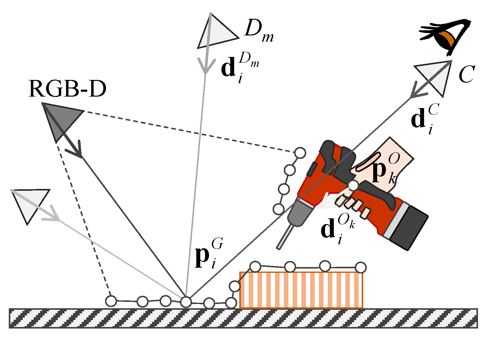
Figure 2.
Overview of the proposed pipeline.
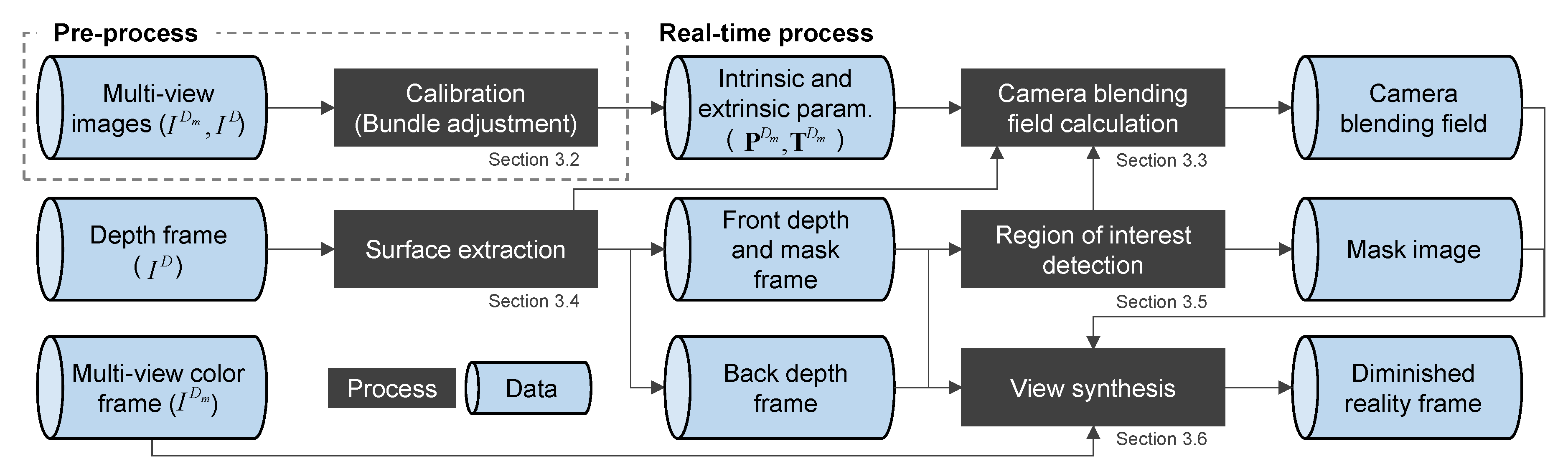
Figure 3.
Setup of the video performance evaluation.

Figure 4.
Qualitative comparison of original view and DR methods provided from Photoshop Content-Aware Fill, surface splatting, and the proposed method.
Figure 4.
Qualitative comparison of original view and DR methods provided from Photoshop Content-Aware Fill, surface splatting, and the proposed method.
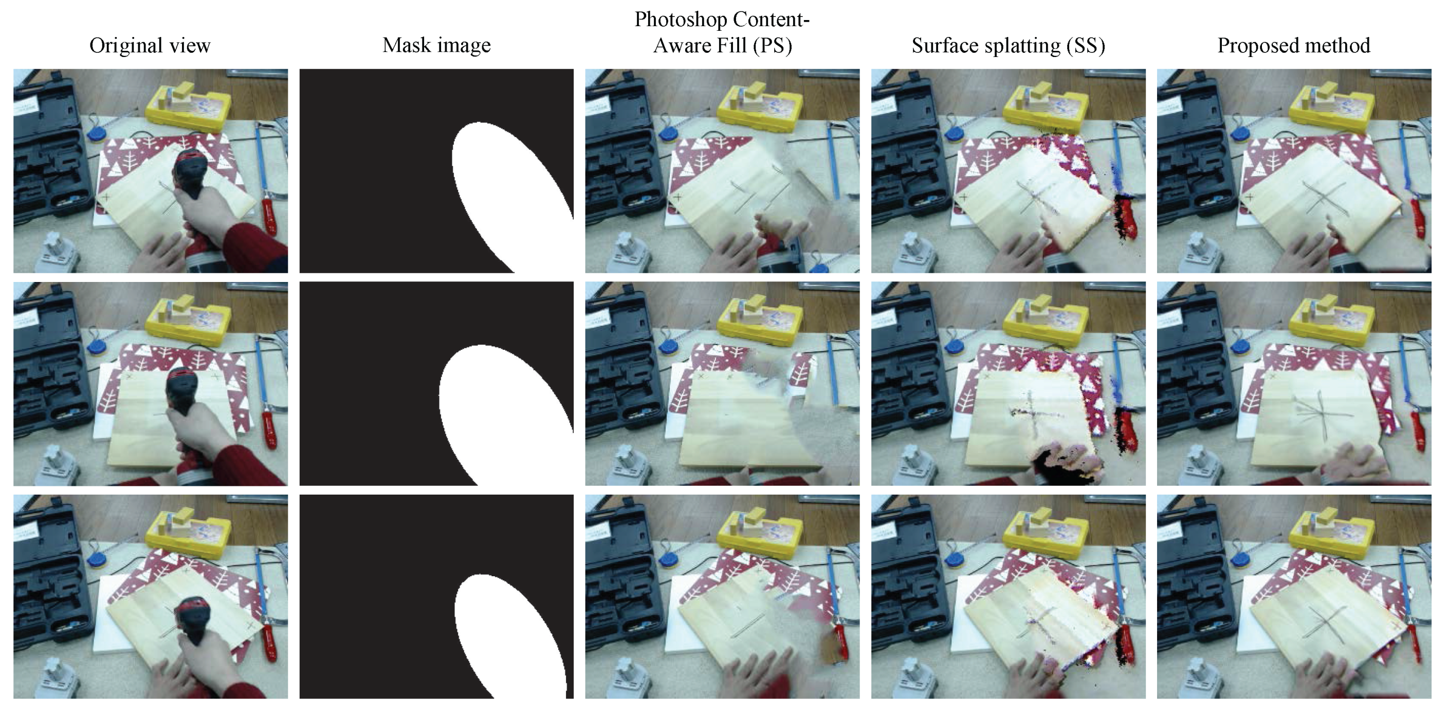
Figure 5.
DR result images of the similarity evaluations.
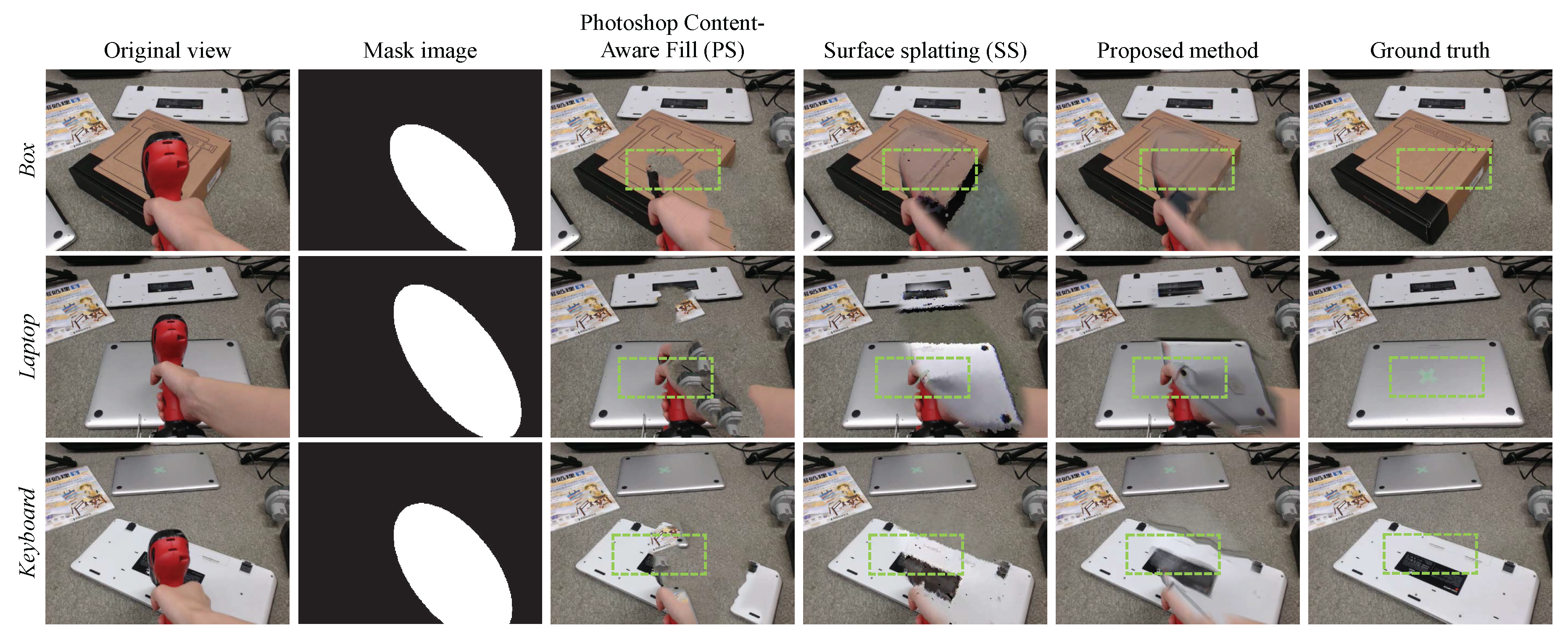
Figure 6.
Partially enlarged results corresponding to the green rectangular regions in Figure 5.
Figure 6.
Partially enlarged results corresponding to the green rectangular regions in Figure 5.

Figure 7.
Statistical DR results of the NCC, PSNR, and SSIM evaluations. Remark: (significance: (**) p < 0.01 and (*) p < 0.05).
Figure 7.
Statistical DR results of the NCC, PSNR, and SSIM evaluations. Remark: (significance: (**) p < 0.01 and (*) p < 0.05).

Table 1.
Characteristics of existing DR methods compared to the proposed method.
| Methods | Background | Object of Interest | User Pose | Multi-View | Depth Search | View-Dependent Properties |
|---|---|---|---|---|---|---|
| Zokai et al. [6] | Static | Static | Pre-calibrated | Yes | Required | No |
| Herling et al. [10] | Static | Static | 6DoF (Homography) | No | Not required | No |
| Kawai et al. [9] | Static | Static | 6DoF (SLAM [14]) | No | Not required | No |
| Li et al. [11] | Static | Dynamic | 6DoF (Homography) | Yes | Not required | Image switching |
| Cosco et al. [4] | Static | Dynamic | 6DoF (AR Marker [15]) | Yes | Not required | ULR-based [8] |
| Jarusirisawad et al. [7] | Dynamic | Dynamic | 6DoF (Virtual Camera) | Yes | Required | No |
| Barnum et al. [12] | Dynamic | Static | 6DoF (Homography) | No | Not required | No |
| Meerits and Saito [13] | Dynamic | Dynamic | 6DoF (AR Marker [15]) | No | Not required | No |
| Proposed | Dynamic | Dynamic | Pre-calibrated | Yes | Not required | ULR-based [8] |
Table 2.
Mean and standard deviation of all methods in the similarity measure experiment.
| NCC | PSNR | SSIM | |
|---|---|---|---|
| Photoshop Content-Aware Fill (PS) | 0.972 ± 0.014 | 18.40 ± 2.35 | 0.773 ± 0.049 |
| Surface splatting (SS) | 0.973 ± 0.013 | 18.44 ± 1.79 | 0.784 ± 0.043 |
| Proposed method | 0.980 ± 0.010 | 19.73 ± 2.03 | 0.801 ± 0.039 |
© 2017 by the authors. Licensee MDPI, Basel, Switzerland. This article is an open access article distributed under the terms and conditions of the Creative Commons Attribution (CC BY) license (http://creativecommons.org/licenses/by/4.0/).
Share and Cite
MDPI and ACS Style
Mori, S.; Maezawa, M.; Saito, H. A Work Area Visualization by Multi-View Camera-Based Diminished Reality. Multimodal Technol. Interact. 2017, 1, 18. https://doi.org/10.3390/mti1030018
AMA Style
Mori S, Maezawa M, Saito H. A Work Area Visualization by Multi-View Camera-Based Diminished Reality. Multimodal Technologies and Interaction. 2017; 1(3):18. https://doi.org/10.3390/mti1030018
Chicago/Turabian StyleMori, Shohei, Momoko Maezawa, and Hideo Saito. 2017. "A Work Area Visualization by Multi-View Camera-Based Diminished Reality" Multimodal Technologies and Interaction 1, no. 3: 18. https://doi.org/10.3390/mti1030018