
3D Numerical Modeling of Zeotropic Mixtures and Pure Working Fluids in an ORC Turbo-Expander


Abstract
:1. Introduction
- A high molecular weight;
- An acceptable evaporating pressure value to reduce both complexity and cost of evaporates;
- A high vapor density to avoid a large volume flow rate, consequently limiting the size of turbines, condensers, and evaporates;
- A positive slope or isentropic saturation vapor curve to prevent the formation of droplets at expansion process in a turbine and therefore avoiding pitting, corrosion, and erosion in turbine blades;
- A positive condensing gauge pressure in order to avoid air leakage into the cycle; and
- Low ozone depleting potential (ODP) and low global warming potential (GWP).
2. Working Fluid Selection and Design Parameters
- (a)
- (b)
- The upper limit of the tip speed must be within 370 m/s [4].
- (c)
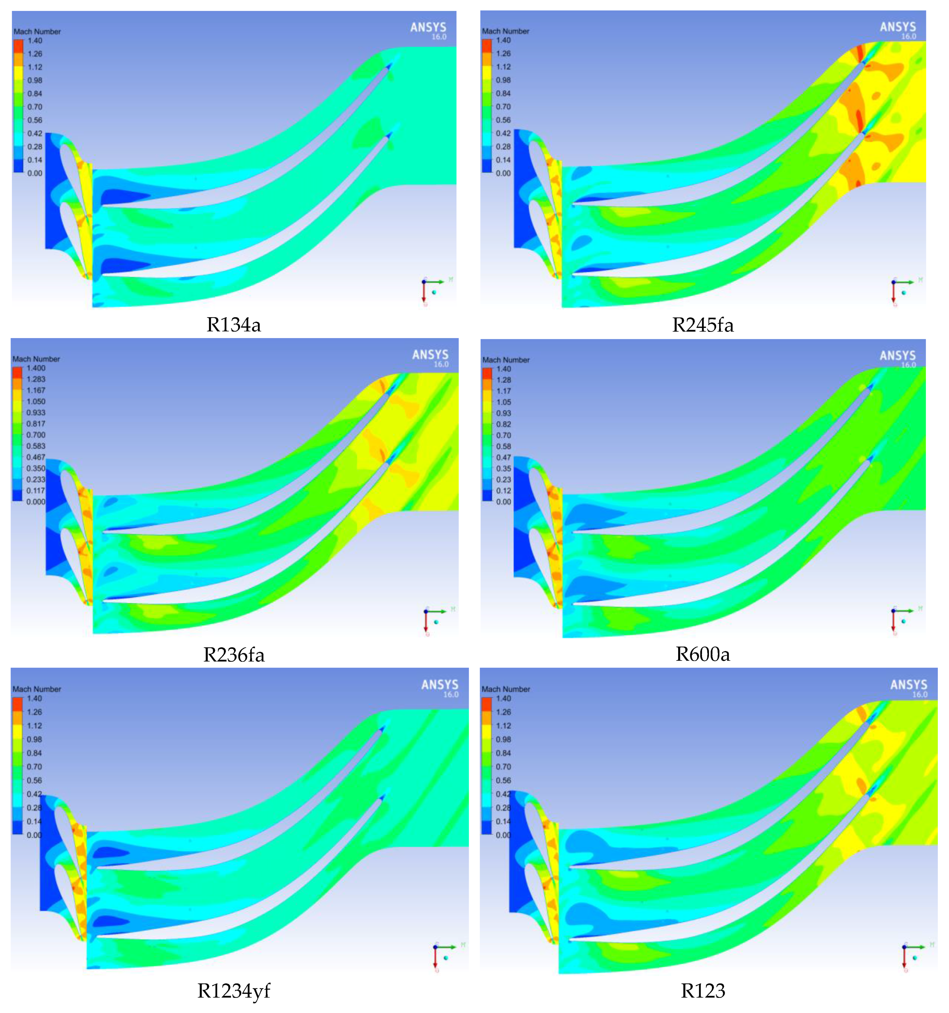
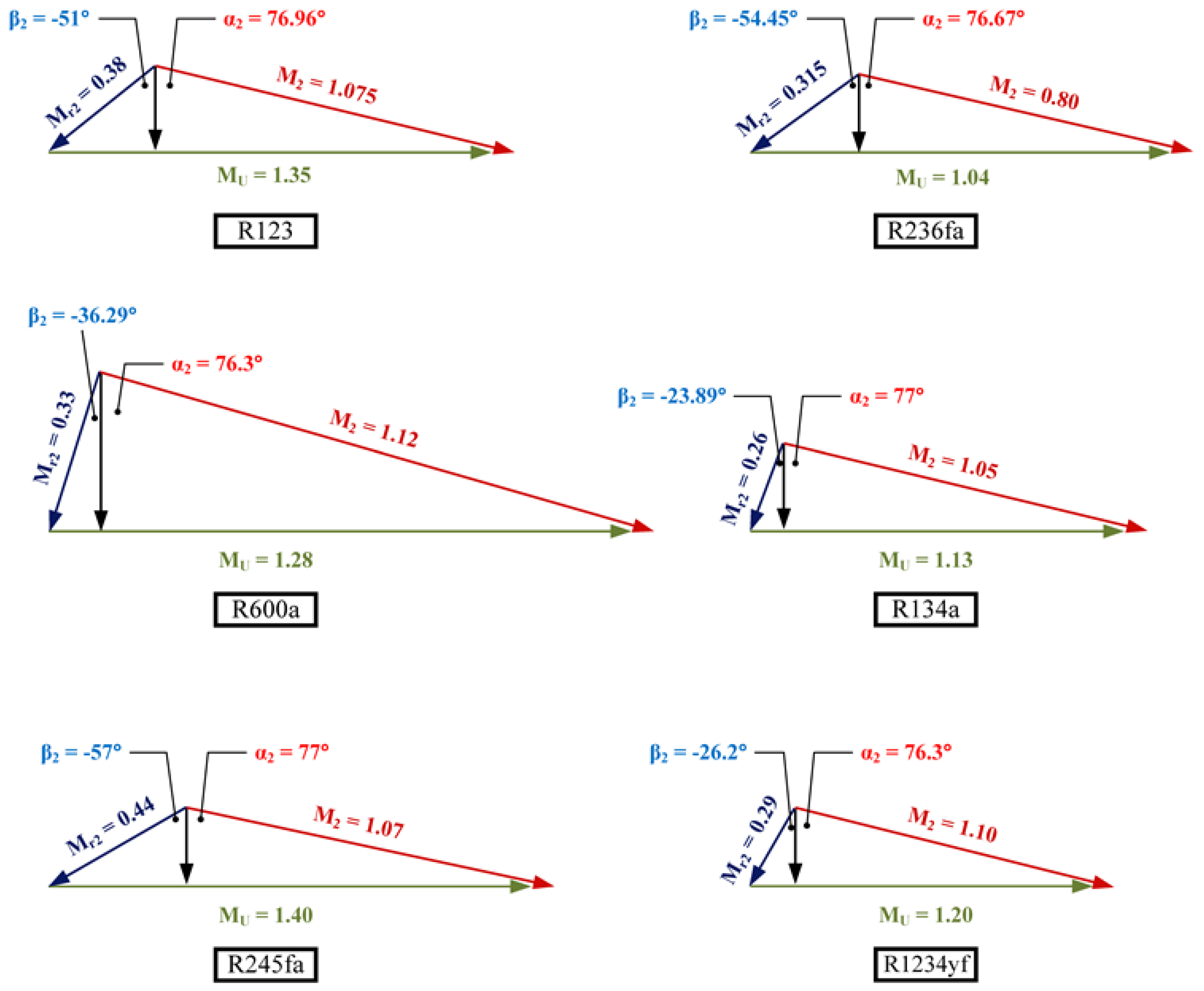
- A maximum relative Mach number is generally recommended in order to avoid a choked flow in the rotor.
- (d)
- The upper limit of the absolute Mach number at the nozzle exit should not exceed 1.8 [4].
- (e)
- (f)
- The tip Mach number lies in the range 0.5–0.7 for automotive turbocharger turbines, while the value of tip Mach number is increased to 1, and choking must be considered for low-temperature turbines (refrigerant expander) (see Cox [21]).
- (g)
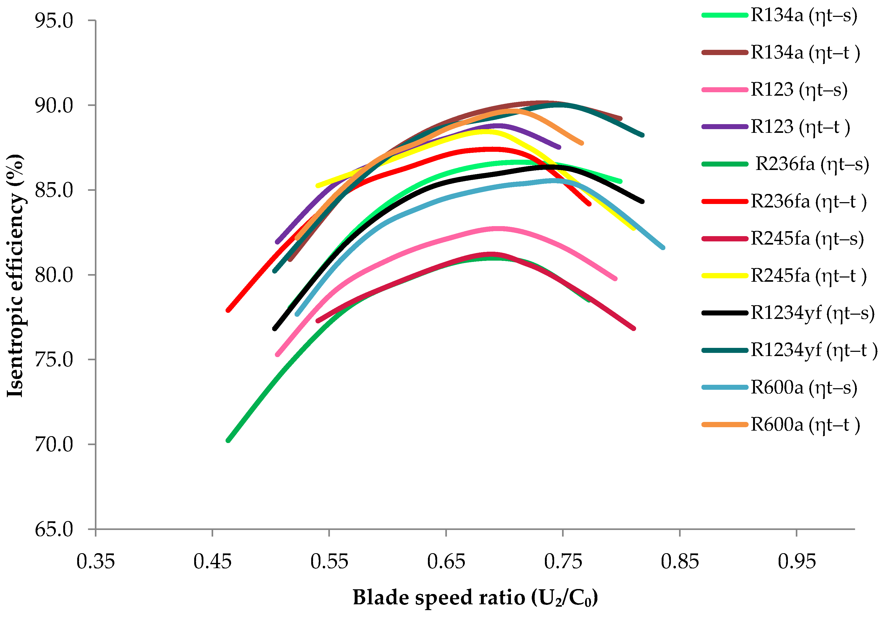
- The blade speed ratio () should be close to 0.7 for most efficient turbines, where C0, the spouting velocity, is the velocity of a jet if the gas was expanded isentropically through a nozzle, and equals (see Cox [21]).
3. Numerical Method
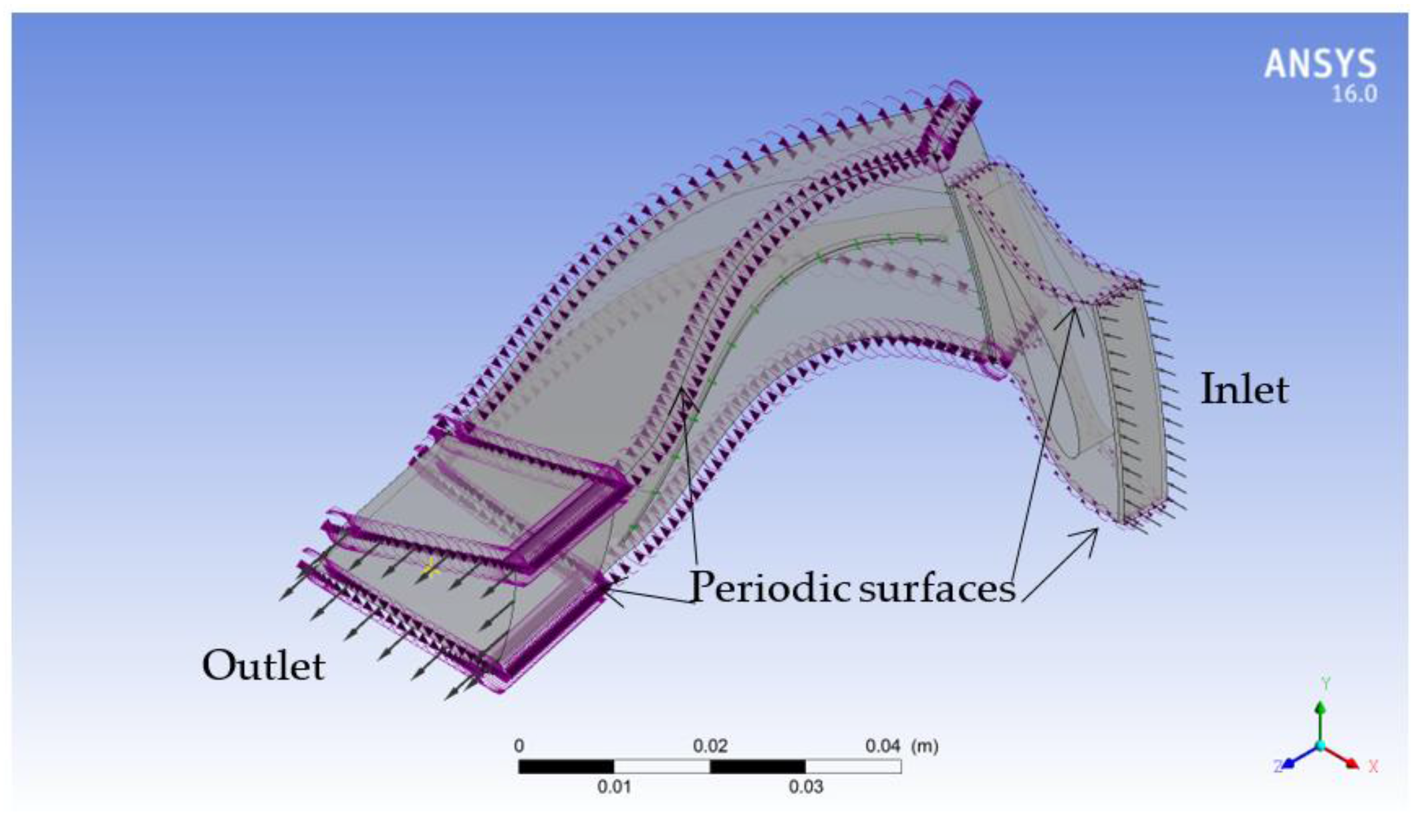
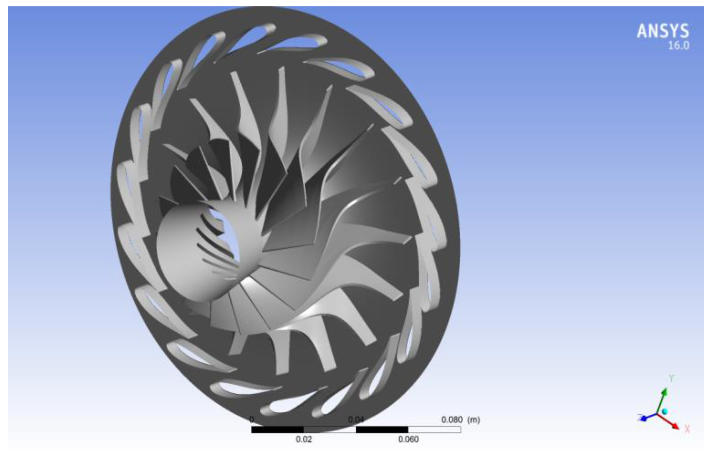
3.1. Computational Domain
3.2. Boundary Conditions
- a)
- The total temperature of 477.6 K and the total pressure of 413.6 kPa were defined at the turbine inlet.
- b)
- The outlet static pressure was 72.4 kPa to produce a pressure ratio (t-s) equal to 5.73.
- c)
- The working fluid that was used in the experimental data of [22] was air and was assumed as an ideal gas in the CFD simulations.
- d)
- The nominal rotational speed for the turbine was set to 71,700 rpm, equal to that of the experimental data [22].
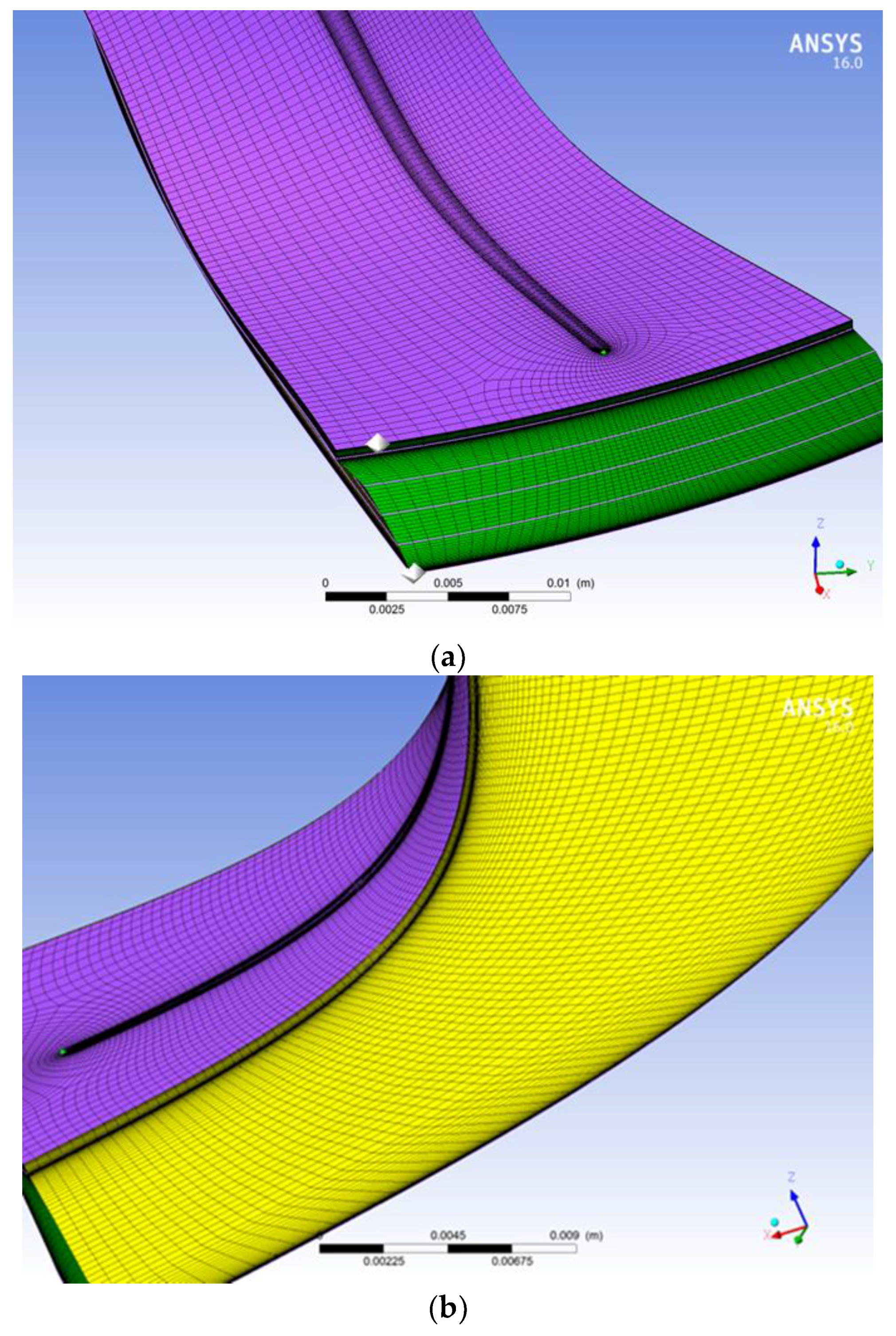
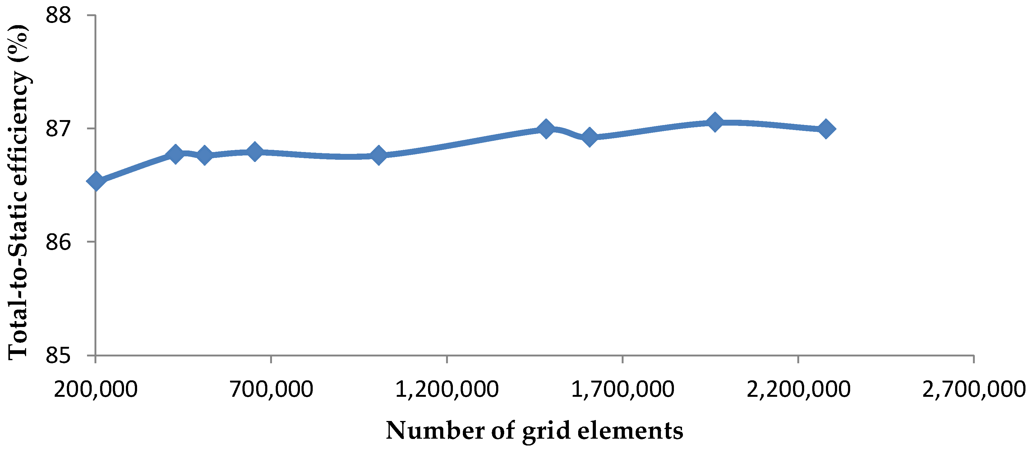
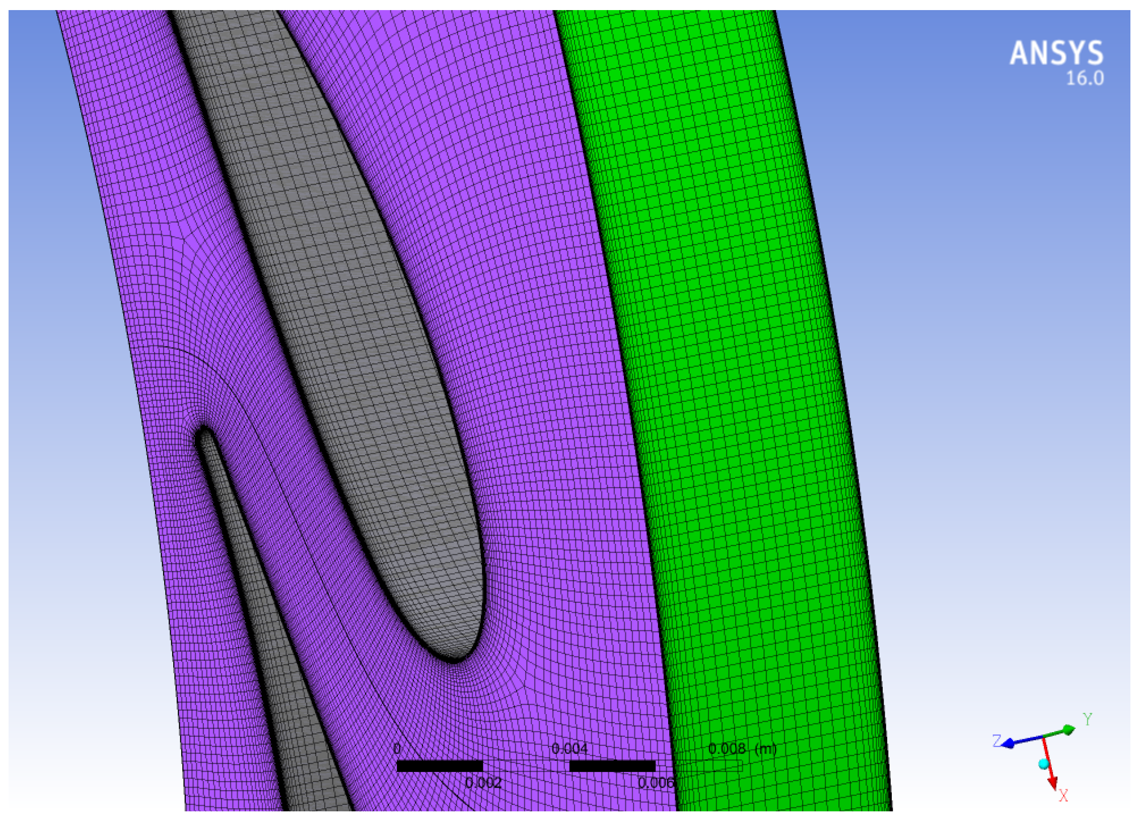
3.3. Mesh
- a)
- Face angle: the angle between the edges of each face within an element. The final mesh analysis of rotor flow passages shows 23.27° for minimum face angle and 156.72° for maximum face angle.
- b)
- Minimum Volume: the minimum volume of each cell. Its value is 1.922 × 10⁻¹⁵ m3.
- c)
- Connectivity Number: the number of elements connected to a single node. Its value is 10.
3.4. Numerical Details
4. Numerical Results and Discussion
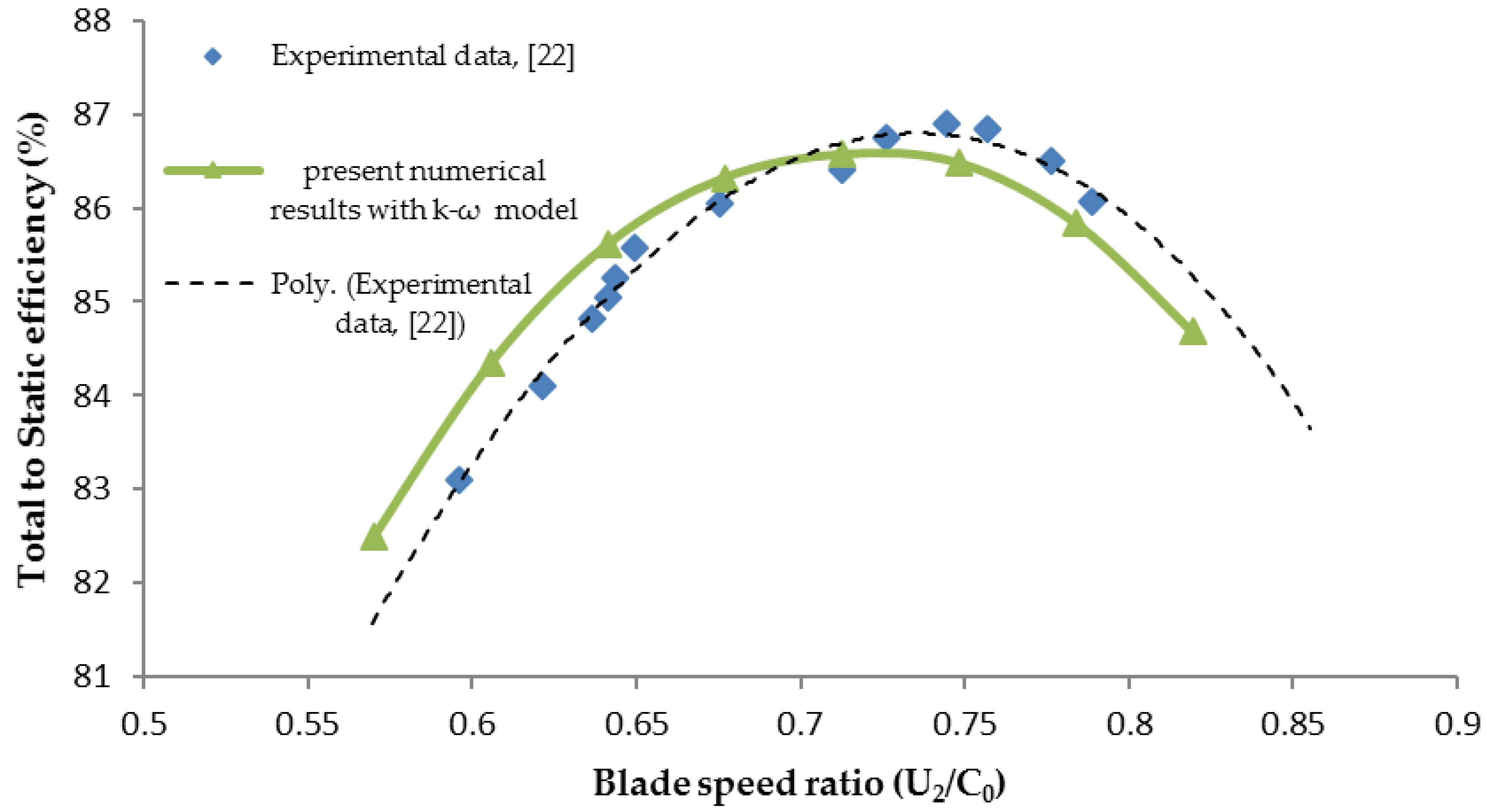
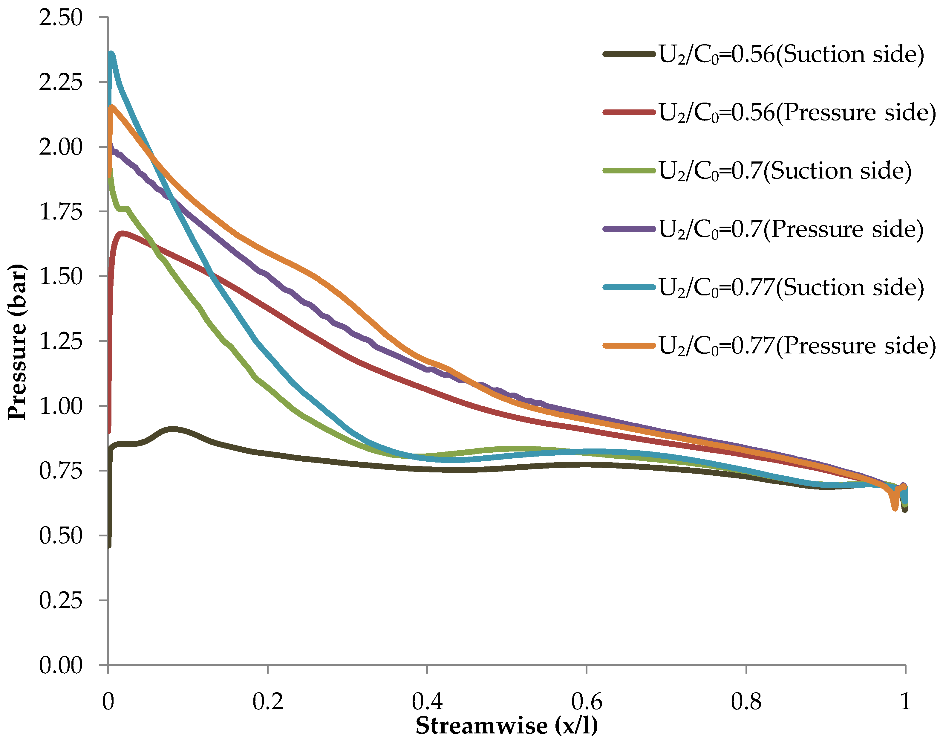
4.1. Validation of the Numerical Results
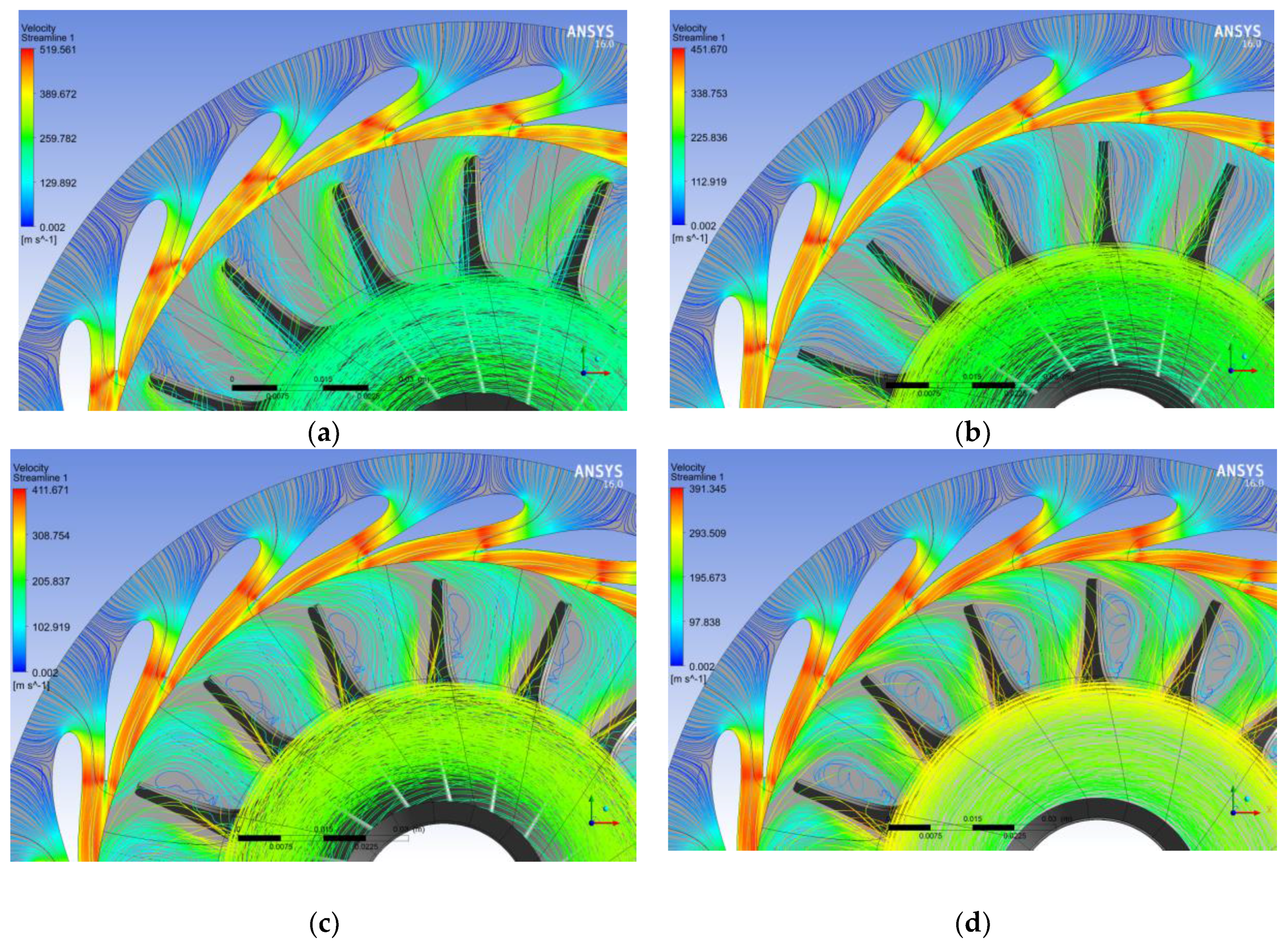
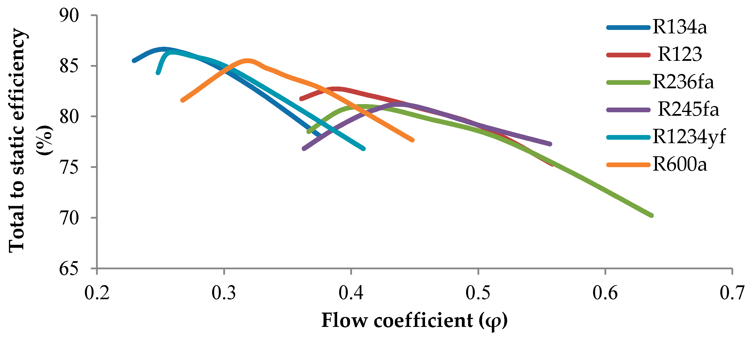
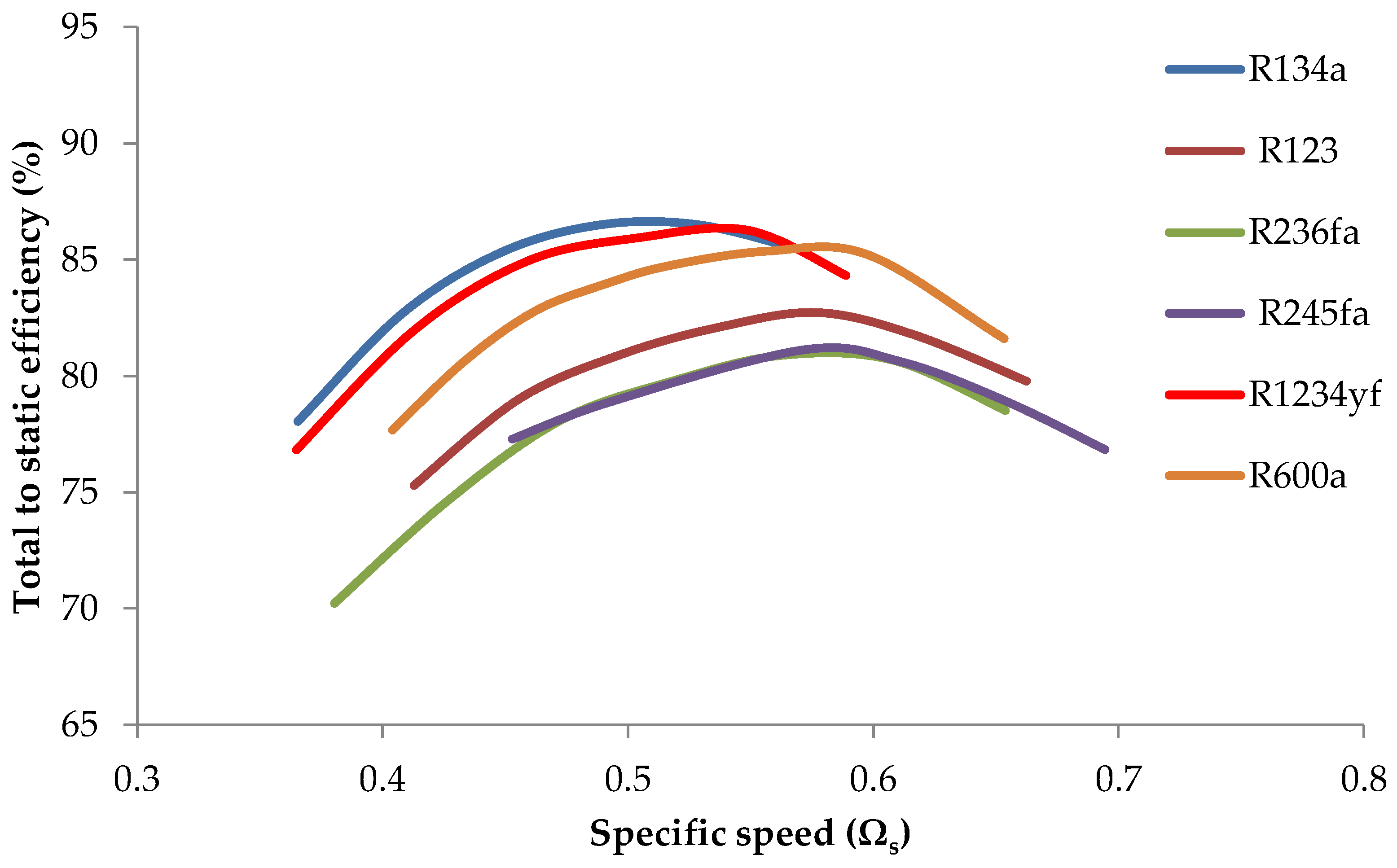
4.2. Numerical Results of Pure Working Fluids
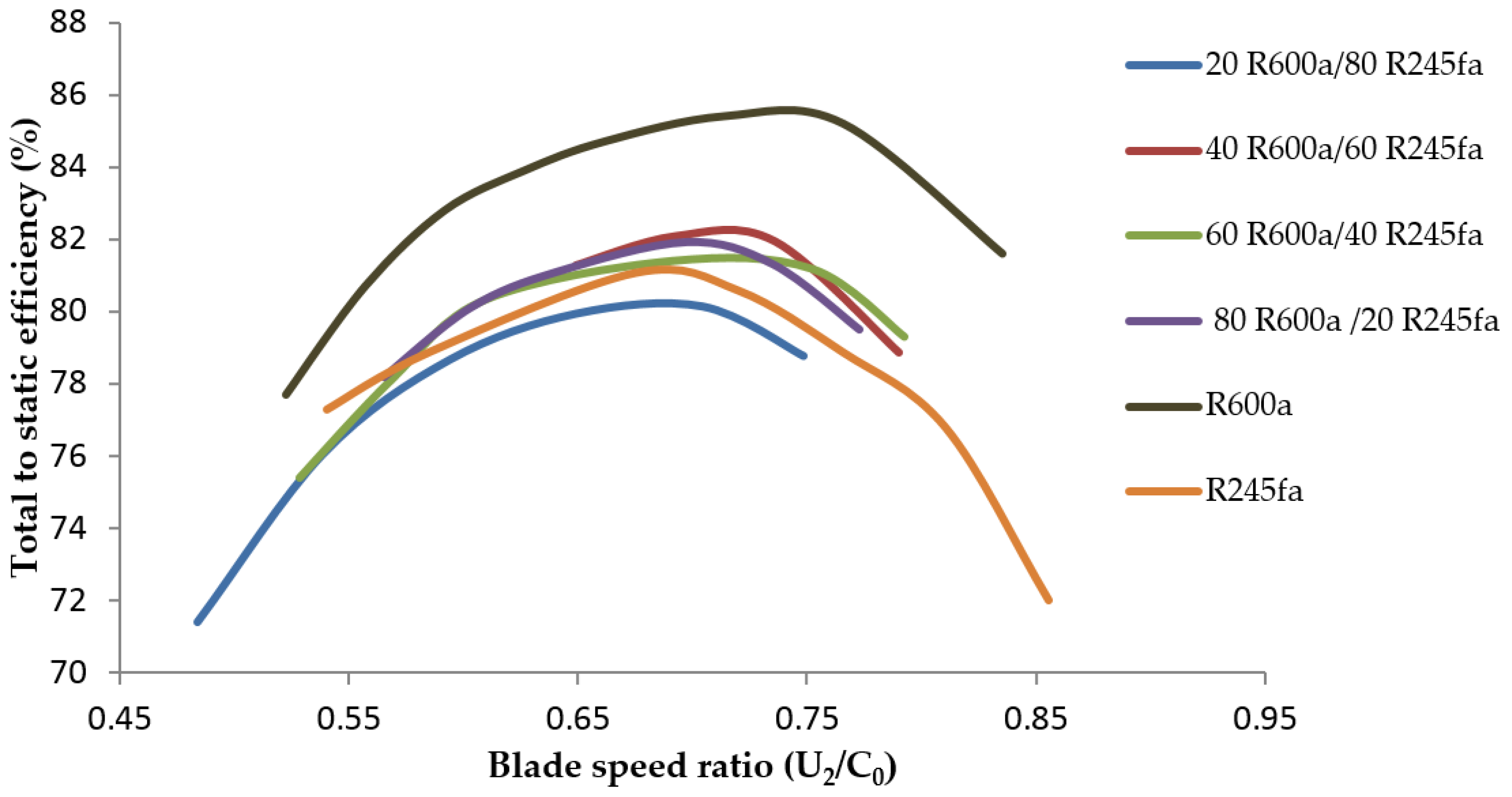
4.3. Numerical Results of Zeotropic Mixtures Working Fluids (R600a/R245fa)
5. Conclusions
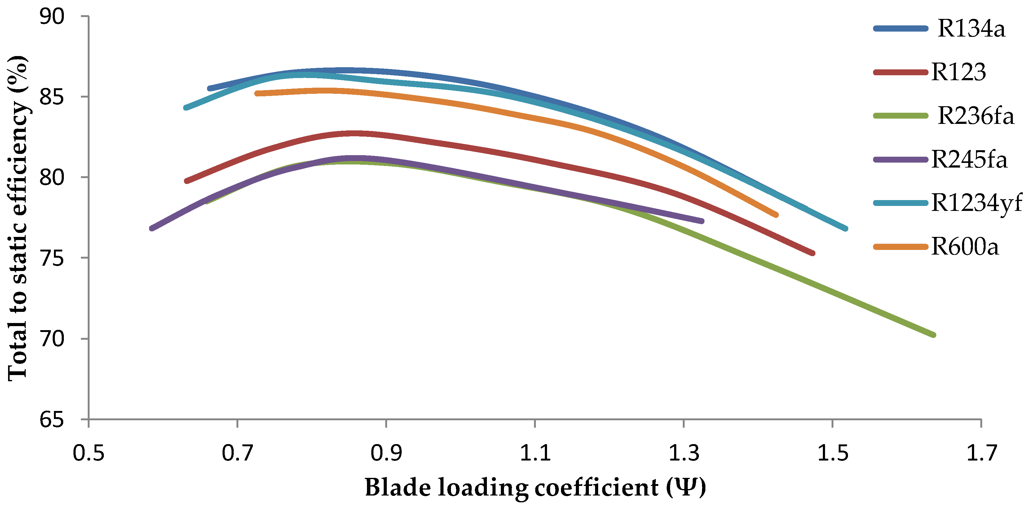
- A major issue for the performance of the ORC turbo-expander is the pressure ratio. The best efficiency for the radial inflow turbine was found for R134a and R1234yf as a result of lower pressure ratios across the stage of 2.20 and 2.25, respectively.
- Due to the relatively high GWP of R134a, which has a value of 1430, it should be replaced with R1234yf, which has a low GWP and shows the same turbine performance as R134a.
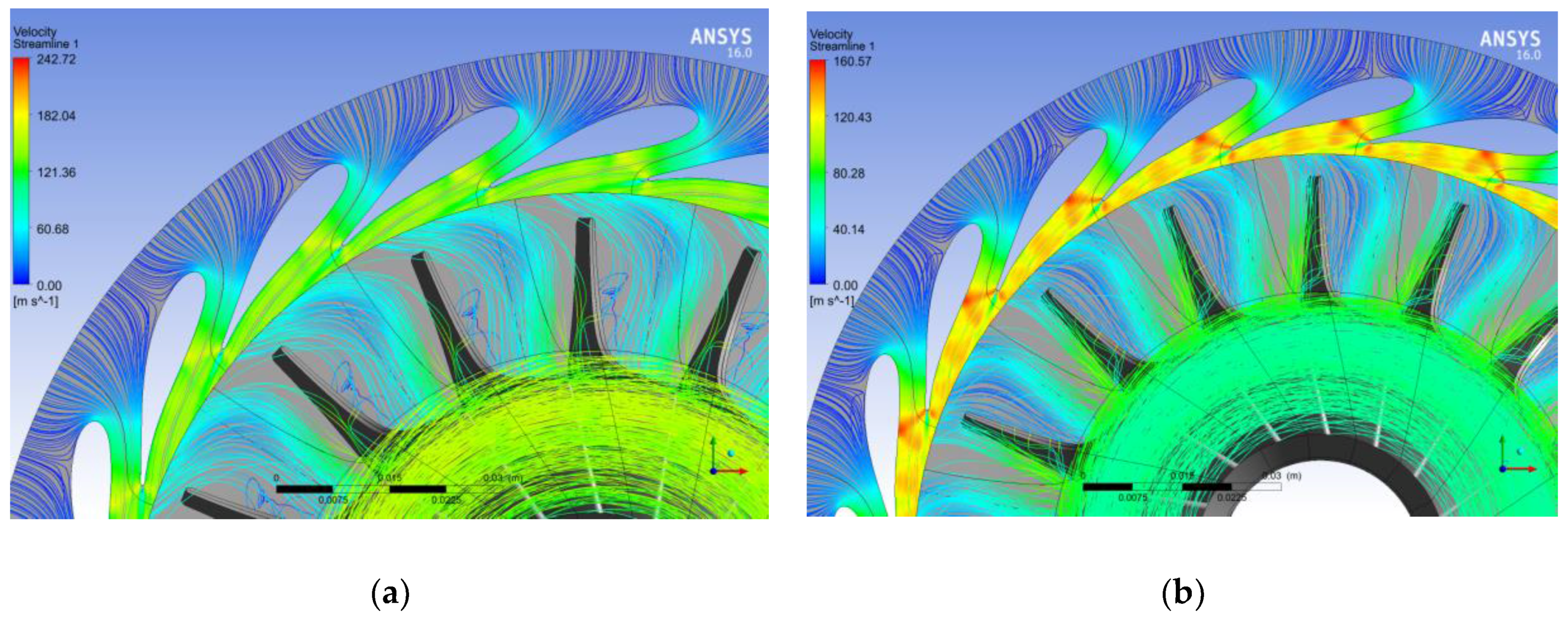
- At off-design operating conditions, the flow enters the rotor with an incidence angle that is either extremely positive or negative, which leads to an increase in incidence energy loss. Consequently, variable-angle nozzle guide vanes with the control system can be used to maintain the optimum incidence angle at off-design conditions. Therefore, the turbine efficiency can be maintained near the design point.
- A multi-stage radial inflow turbine can be utilized for working fluids (R245fa and R236fa) with high pressure ratios to keep a moderate pressure ratio across a stage.
Acknowledgments
Author Contributions
Conflicts of Interest
Nomenclature
Symbols
| a | sonic velocity (m·s−1) |
| C | absolute velocity (m·s−1) |
| C0 | spouting velocity (m·s−1) |
| h | enthalpy (J·kg−1) |
| M | Mach number (−) |
| N | rotational speed (RPM) |
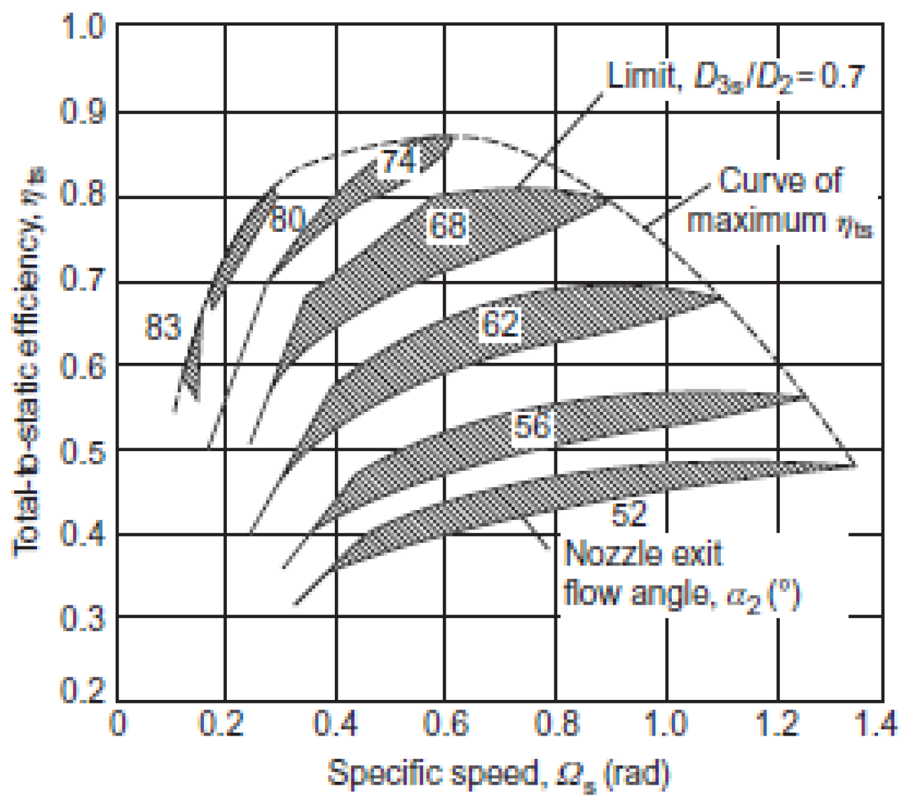
| ΩS | specific speed (rad (m3/s)0.5/(J/kg)0.75) |
| Q | volume flow rate (m3·s−1) |
| p | pressure (MPa) |
| Pr | pressure ratio (–) |
| T | temperature (K) |
| U | blade speed (m·s−1) |
| y+ | non-dimensional grid spacing at the wall (–) |
Greek Letters
| α | absolute flow angle (degree) |
| β | relative flow angle (degree) |
| η | efficiency (–) |
| Δ | difference |
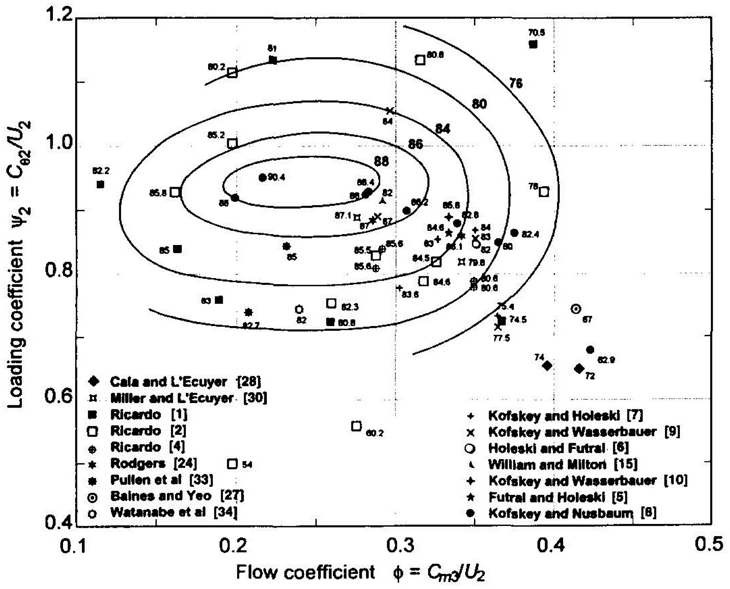
| Φ | flow coefficient (–) |
| Ψ | blade loading coefficient (–) |
| ω | angular velocity (rad/s) |
Subscripts
| 0 | stagnation value |
| 1 | stator inlet station |
| 2 | rotor inlet station |
| 3 | stage outlet station |
| c | critical |
| is | isentropic |
| s | static |
| t-s | total-to-static |
| t-t | total-to-total |
Acronyms
| ASHRAE | American Society of Heating, Refrigerating, and Air-Conditioning Engineers |
| ATM | automatic topology meshing |
| 3D | three-dimensional |
| CFD | computational fluid dynamics |
| GWP | global warming potential |
| ORC | Organic Rankine Cycle |
| ODP | ozone depleting potential |
| RANS | Reynolds-averaged Navier–Stokes |
References
- Quoilin, S.; Van Den Broek, M.; Declaye, S.; Dewallef, P.; Lemort, V. Techno-economic survey of Organic Rankine Cycle (ORC) systems. Renew. Sustain. Energy Rev. 2013, 22, 168–186. [Google Scholar] [CrossRef]
- Johnson, I.; Choate, W.T.; Davidson, A. Waste Heat Recovery. Technology and Opportunities in US Industry; BCS, Inc.: Laurel, MD, USA, 2008. [Google Scholar]
- Qiu, G.; Liu, H.; Riffat, S. Expanders for micro-CHP systems with organic Rankine cycle. Appl. Therm. Eng. 2011, 31, 3301–3307. [Google Scholar] [CrossRef]
- Quoilin, S.; Declaye, S.; Legros, A.; Guillaume, L.; Lemort, V. Working fluid selection and operating maps for Organic Rankine Cycle expansion machines. In Proceedings of the 21st International Compressor Conference, Purdue, West Lafayette, IN, USA, 16–19 July 2012; p. 10.
- Bao, J.; Zhao, L. A review of working fluid and expander selections for organic Rankine cycle. Renew. Sustain. Energy Rev. 2013, 24, 325–342. [Google Scholar] [CrossRef]
- Sauret, E.; Rowlands, A.S. Candidate radial-inflow turbines and high-density working fluids for geothermal power systems. Energy 2011, 36, 4460–4467. [Google Scholar] [CrossRef]
- Lopez Sanz, E. Study on a Radial Turbine Stage with Inlet Guide Vanes for an ORC Process with an Electrical Output of 3.5 kW. Master’s Thesis, Universität Stuttgart, Stuttgart, Germany, 2013. [Google Scholar]
- Wong, C.S.; Krumdieck, S. Scaling of Gas Turbine From Air to Refrigerants for Organic Rankine Cycle Using Similarity Concept. J. Eng. Gas Turbines Power 2016, 138, 061701. [Google Scholar] [CrossRef]
- Bajaj, S.S.; Patil, H.B.; Kudal, G.B.; Shisode, S.P. Organic Rankine Cycle and Its Working Fluid Selection—A Review. Int. J. Curr. Eng. Technol. 2016, 4, 20–26. [Google Scholar]
- Tchanche, B.F.; Lambrinos, G.; Frangoudakis, A.; Papadakis, G. Low-grade heat conversion into power using organic Rankine cycles—A review of various applications. Renew. Sustain. Energy Rev. 2011, 15, 3963–3979. [Google Scholar] [CrossRef]
- Vélez, F.; Segovia, J.J.; Martín, M.C.; Antolín, G.; Chejne, F.; Quijano, A. A technical, economical and market review of organic Rankine cycles for the conversion of low-grade heat for power generation. Renew. Sustain. Energy Rev. 2012, 16, 4175–4189. [Google Scholar] [CrossRef]
- Schuster, A.; Karellas, S.; Kakaras, E.; Spliethoff, H. Energetic and economic investigation of Organic Rankine Cycle applications. Appl. Therm. Eng. 2009, 29, 1809–1817. [Google Scholar] [CrossRef]
- Gao, H.; Liu, C.; He, C.; Xu, X.; Wu, S.; Li, Y. Performance analysis and working fluid selection of a supercritical organic Rankine cycle for low grade waste heat recovery. Energies 2012, 5, 3233–3247. [Google Scholar] [CrossRef]
- Jumel, S.; Feidt, M.; Kheiri, A. Working fluid selection and performance comparison of subcritical and supercritical organic Rankine cycle (ORC) for low-temperature waste heat recovery. In Proceedings of the ECEEE Summer Study on Energy Efficiency in Industry, Arnhem, The Netherlands, 11–14 September 2012; pp. 559–569.
- Fiaschi, D.; Manfrida, G.; Maraschiello, F. Thermo-fluid dynamics preliminary design of turbo-expanders for ORC cycles. Appl. Energy 2012, 97, 601–608. [Google Scholar] [CrossRef]
- Aghahosseini, S.; Dincer, I. Exergo-environmental analysis of renewable/waste heat based organic rankine cycle using different working fluid. In Proceedings of the Global Conference on Global Warming, Lisbon, Portugal, 11–14 July 2011.
- Masheiti, S.; Agnew, B.; Walker, S. An evaluation of R134a and R245fa as the working fluid in an Organic Rankine Cycle energized from a low temperature geothermal energy source. J. Energy Power Eng. 2011, 5, 392–402. [Google Scholar]
- Li, Y.R.; Du, M.T.; Wu, C.M.; Wu, S.Y.; Liu, C. Potential of organic Rankine cycle using zeotropic mixtures as working fluids for waste heat recovery. Energy 2014, 77, 509–519. [Google Scholar] [CrossRef]
- Dixon, S.L.; Hall, C. Fluid Mechanics and Thermodynamics of Turbomachinery; Butterworth-Heinemann: Oxford, UK, 2013. [Google Scholar]
- Chen, H.; Baines, N.C. The aerodynamic loading of radial and mixed-flow turbines. Int. J. Mech. Sci. 1994, 36, 63–79. [Google Scholar] [CrossRef]
- Cox, G.D. The Practical Design of Turbocharger Turbines Using a Throughflow-Based Optimisation Process. In Proceedings of the ASME Turbo Expo: Turbine Technical Conference and Exposition, Copenhagen, Denmark, 11–15 June 2012; pp. 703–713.
- Jones, A.C. Design and test of a small, high pressure ratio radial turbine. In Proceedings of the ASME International Gas Turbine and Aeroengine Congress and Exposition, The Hague, The Netherlands, 13–16 June 1994.
- Sauret, E. Open design of high pressure ratio radial-inflow turbine for academic validation. In Proceedings of the ASME International Mechanical Engineering Congress and Exposition, Houston, TX, USA, 9–15 November 2012; pp. 3183–3197.
- Siggeirsson, E.M.V.; Gunnarsson, S. Conceptual Design Tool for Radial Turbines. Master’s Thesis, Chalmers University of Technology, Gothenburg, Sweden, 2015. [Google Scholar]
- Wong, C.S. Design-to-Resource (DTR) Using SMC Turbine Adaptive Strategy: Design Process of Low Temperature Organic Rankine Cycle (LT-ORC). Ph.D. Thesis, University of Canterbury, Christchurch, New Zealand, 2015. [Google Scholar]
- Peng, D.Y.; Robinson, D.B. A new two-constant equation of state. Ind. Eng. Chem. Fundam. 1976, 15, 59–64. [Google Scholar] [CrossRef]
- Sauret, E.; Gu, Y. Three-dimensional off-design numerical analysis of an organic Rankine cycle radial-inflow turbine. Appl. Energy 2014, 135, 202–211. [Google Scholar] [CrossRef]
- Hung, T.C. Waste heat recovery of organic Rankine cycle using dry fluids. Energy Convers. Manag. 2001, 42, 539–553. [Google Scholar] [CrossRef]
- NIST Reference Fluid Thermodynamic and Transport Properties (REFPROP), Version 9.0; National Institute of Standards and Technology: Gaithersburg, MD, USA, 2010.
- Japikse, D.; Baines, N.C. Introduction to Turbomachinery; Concepts ETI Inc.: Norwich, UK; Oxford University Press: Oxford, UK, 1997. [Google Scholar]


| Working Fluids | Physical Properties | ASHRAE Safety Group | Environmental Data | |||||
|---|---|---|---|---|---|---|---|---|
| Slope | Critical temperature (K) | Critical pressure (kPa) | Molecular weight (kg/kmol) | ODP | GWP (100 Years) | Atmospheric Life Time (Year) | ||
| R245fa | Positive | 447.4 | 3.93 | 134.05 | A1 | 0 | 950 | 7.6 |
| R236fa | Positive | 398.07 | 3.2 | 152.04 | A1 | 0 | 9810 | 242 |
| R123 | Positive | 456.7 | 3.66 | 152.93 | B1 | 0.02 | 77 | 1.3 |
| R600a | Positive | 408 | 3.64 | 58.122 | A3 | 0 | 8 | 1 |
| R134a | Wet | 374 | 4.06 | 102.03 | A1 | 0 | 1430 | 14 |
| R1234yf | Positive | 367.85 | 3.38 | 114.04 | A2L | 0 | <1 | 0.029 |
| Working Fluid | Inlet turbine pressure (kPa) | Inlet turbine temperature (K) | Outlet turbine pressure (kPa) | Outlet turbine temperature (K) | Pressure ratio (Pr) | Rotational turbine speed (RPM) |
|---|---|---|---|---|---|---|
| R245fa | 1178 | 370 | 166 | 313 | 7.10 | 31098 |
| R236fa | 1814 | 370 | 286 | 313 | 6.34 | 27193 |
| R123 | 731 | 370 | 111 | 313 | 6.59 | 29076 |
| R600a | 1872 | 370 | 395 | 313 | 4.74 | 40219 |
| R134a | 3234 | 370 | 1012 | 313 | 3.20 | 24403 |
| R1234yf | 3242 | 370 | 999 | 313 | 3.25 | 22258 |
© 2017 by the authors. Licensee MDPI, Basel, Switzerland. This article is an open access article distributed under the terms and conditions of the Creative Commons Attribution (CC BY) license ( http://creativecommons.org/licenses/by/4.0/).
Share and Cite
Gad-el-Hak, I.; Hussin, A.E.; Hamed, A.M.; Mahmoud, N.A. 3D Numerical Modeling of Zeotropic Mixtures and Pure Working Fluids in an ORC Turbo-Expander. Int. J. Turbomach. Propuls. Power 2017, 2, 2. https://doi.org/10.3390/ijtpp2010002
Gad-el-Hak I, Hussin AE, Hamed AM, Mahmoud NA. 3D Numerical Modeling of Zeotropic Mixtures and Pure Working Fluids in an ORC Turbo-Expander. International Journal of Turbomachinery, Propulsion and Power. 2017; 2(1):2. https://doi.org/10.3390/ijtpp2010002
Chicago/Turabian StyleGad-el-Hak, Ibrahim, Ahmed E. Hussin, Ashraf M. Hamed, and Nabil A. Mahmoud. 2017. "3D Numerical Modeling of Zeotropic Mixtures and Pure Working Fluids in an ORC Turbo-Expander" International Journal of Turbomachinery, Propulsion and Power 2, no. 1: 2. https://doi.org/10.3390/ijtpp2010002