
Effect of Distortion on Turbofan Tonal Noise at Cutback with Hybrid Methods †

 ,
, 
Abstract
:1. Introduction
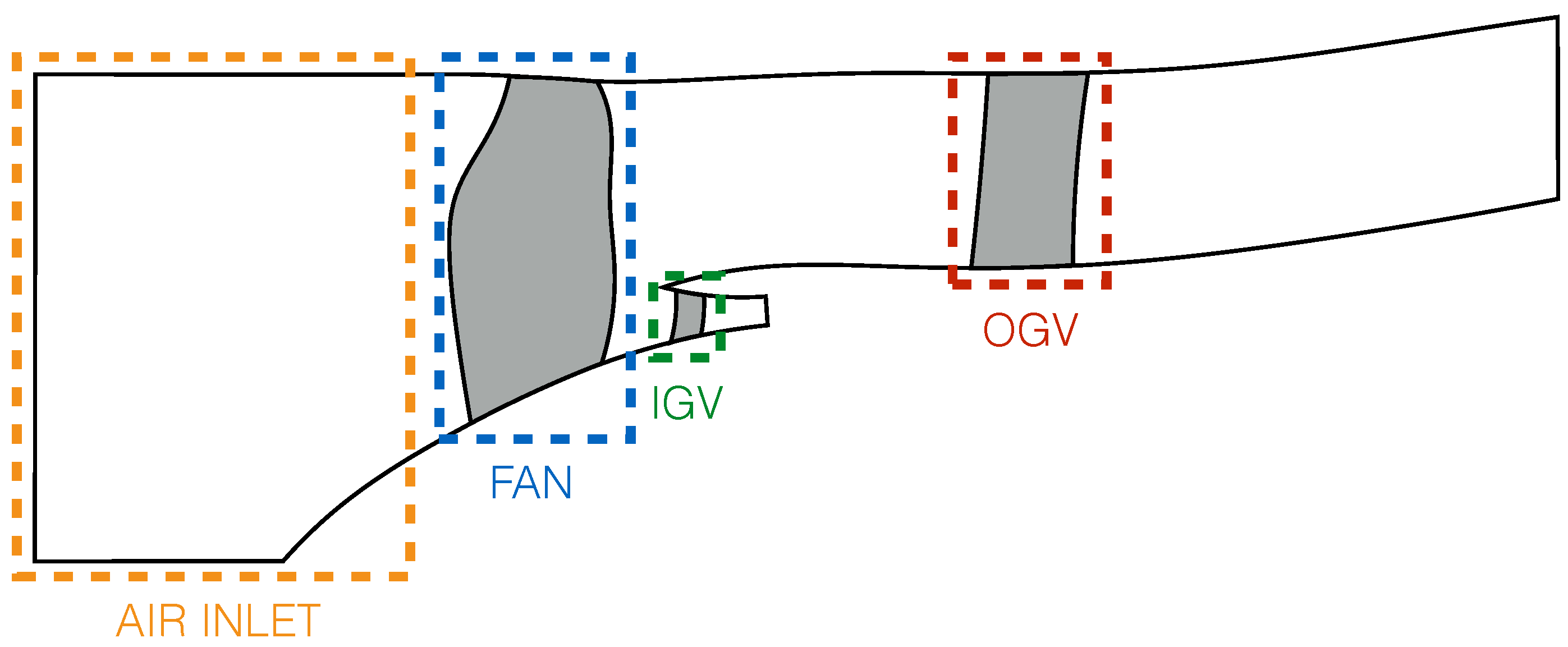
2. Engine Model
3. Methodology
3.1. CFD Simulation
3.1.1. CFD Solver and Numerical Parameters
3.1.2. Mesh
3.1.3. Convergence
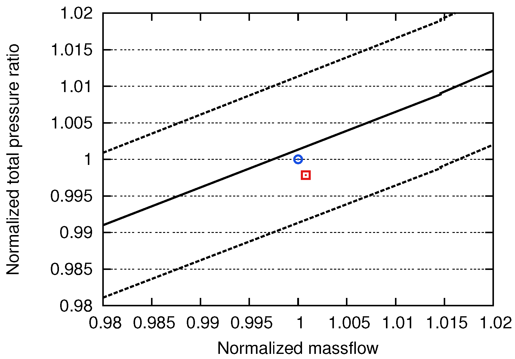
3.1.4. Operating Point
3.2. Acoustic Prediction
3.2.1. Goldstein’s Analogy
- WSI mechanism:
- DRI mechanism:where stands for the Fourier transform of the blade or vane loading. The main difference between these two mechanisms appears in the source frequencies involved in the radiation at a particular frequency. On the one hand, the sound emitted by the WSI mechanism at nBPF is only caused by the fluctuations of the loadings on stator vanes at the same frequency (). On the other hand, the sound emitted by the DRI mechanism at nBPF comes from the fluctuations of the loadings on rotor blades at all frequencies ( with m going from to ), because of the rotational movement of the sources.
3.2.2. Application
4. Results
4.1. Aerodynamic Analysis
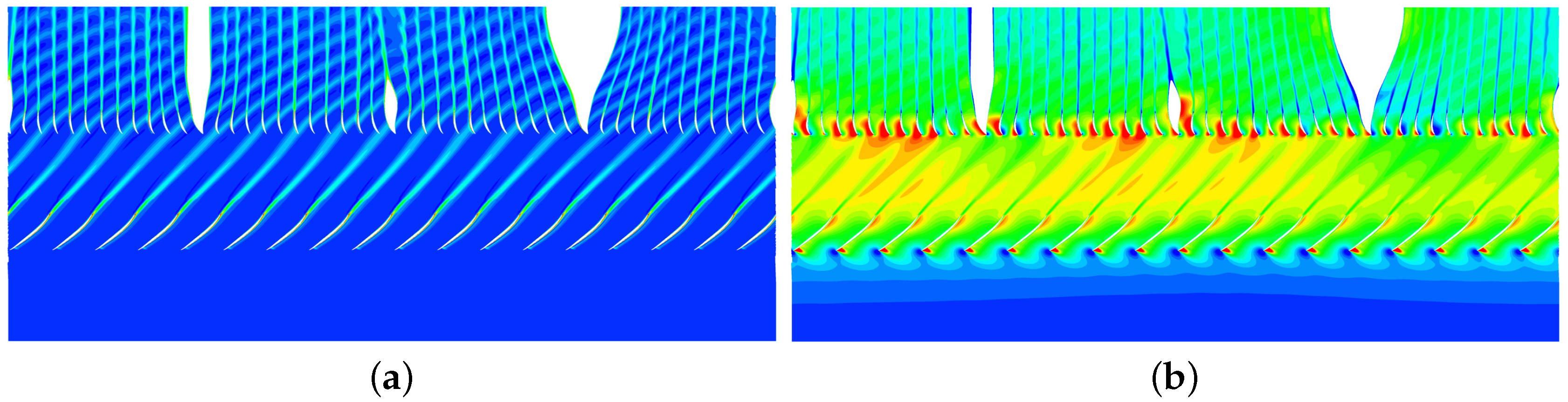
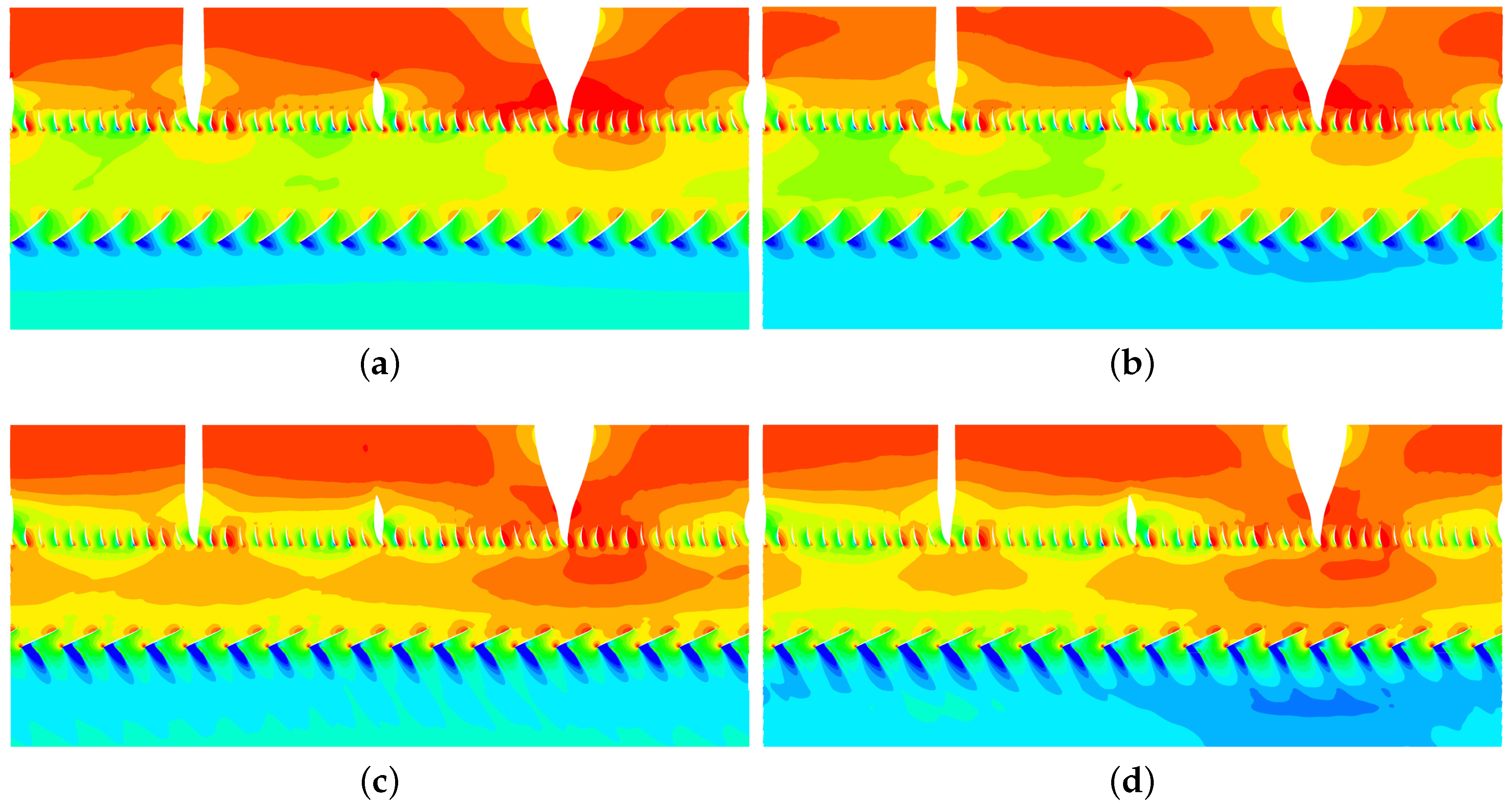
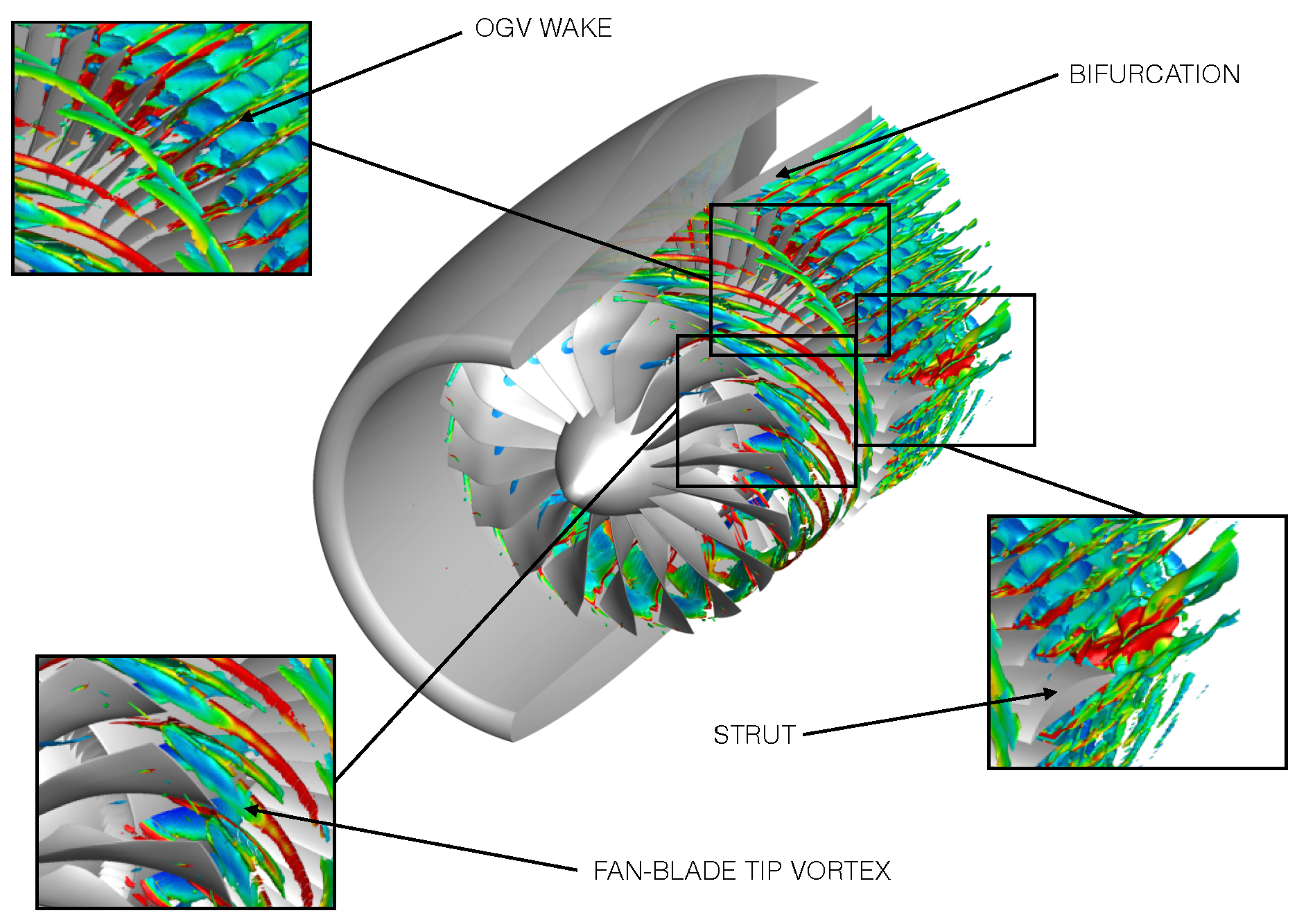
4.1.1. Basic Flow Patterns
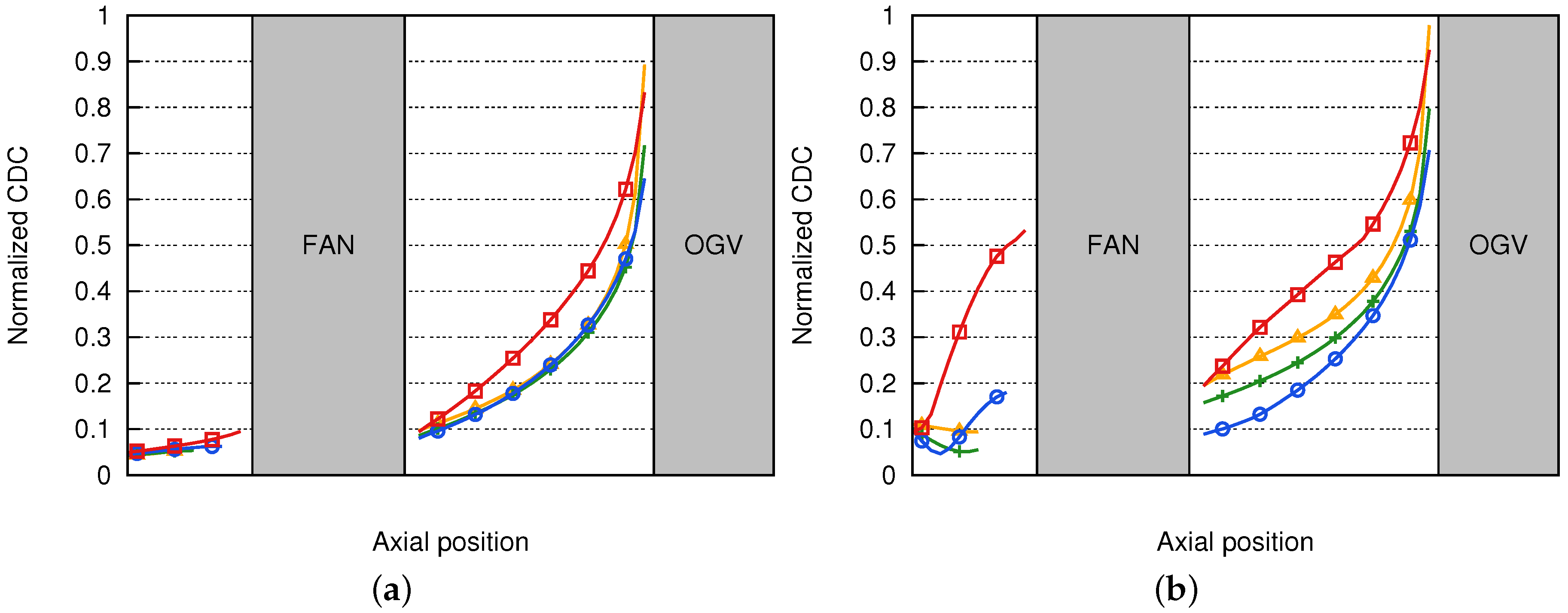
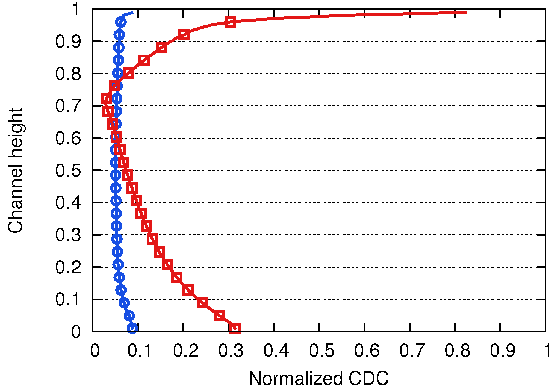
4.1.2. Quantification of the Distortion
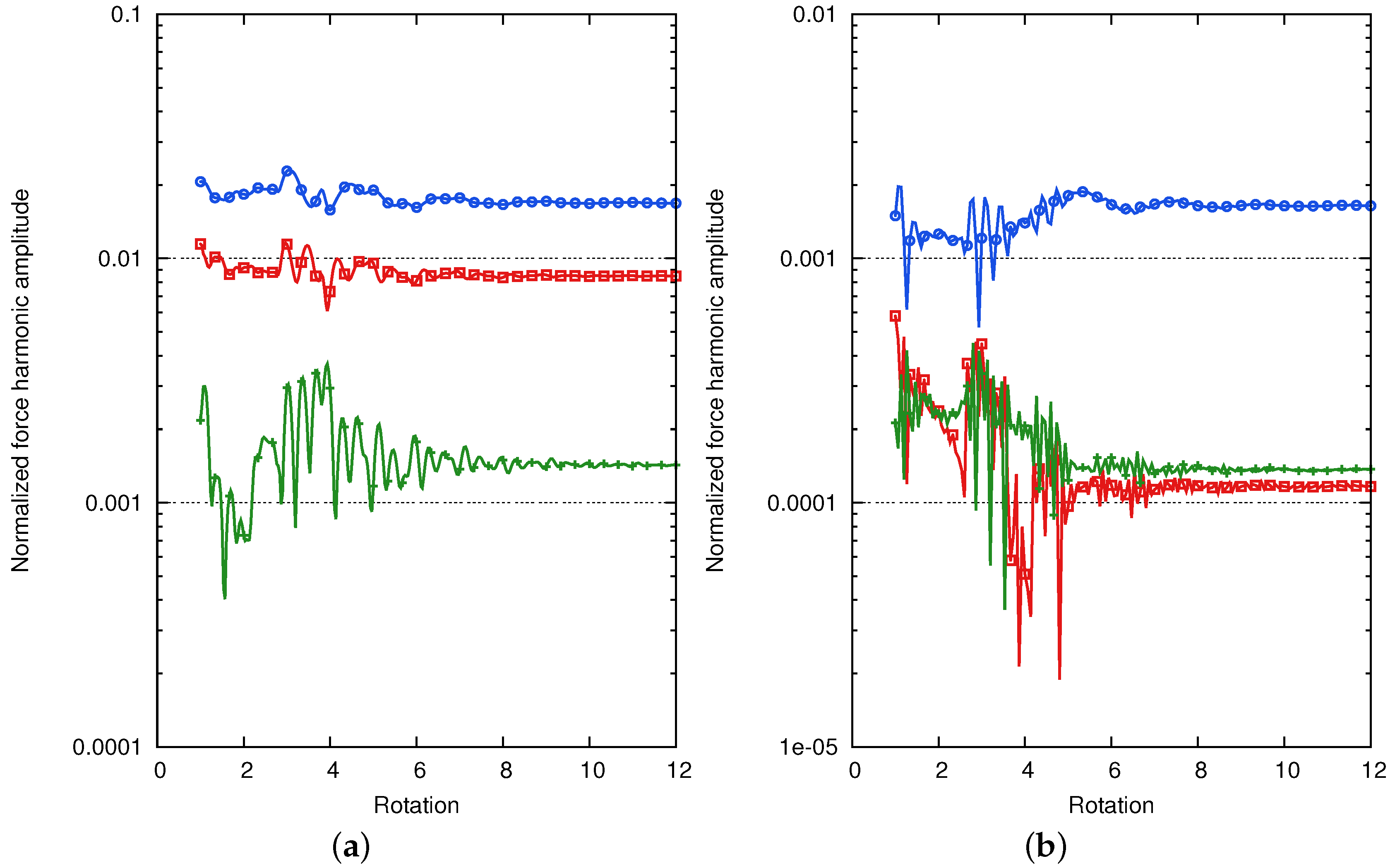
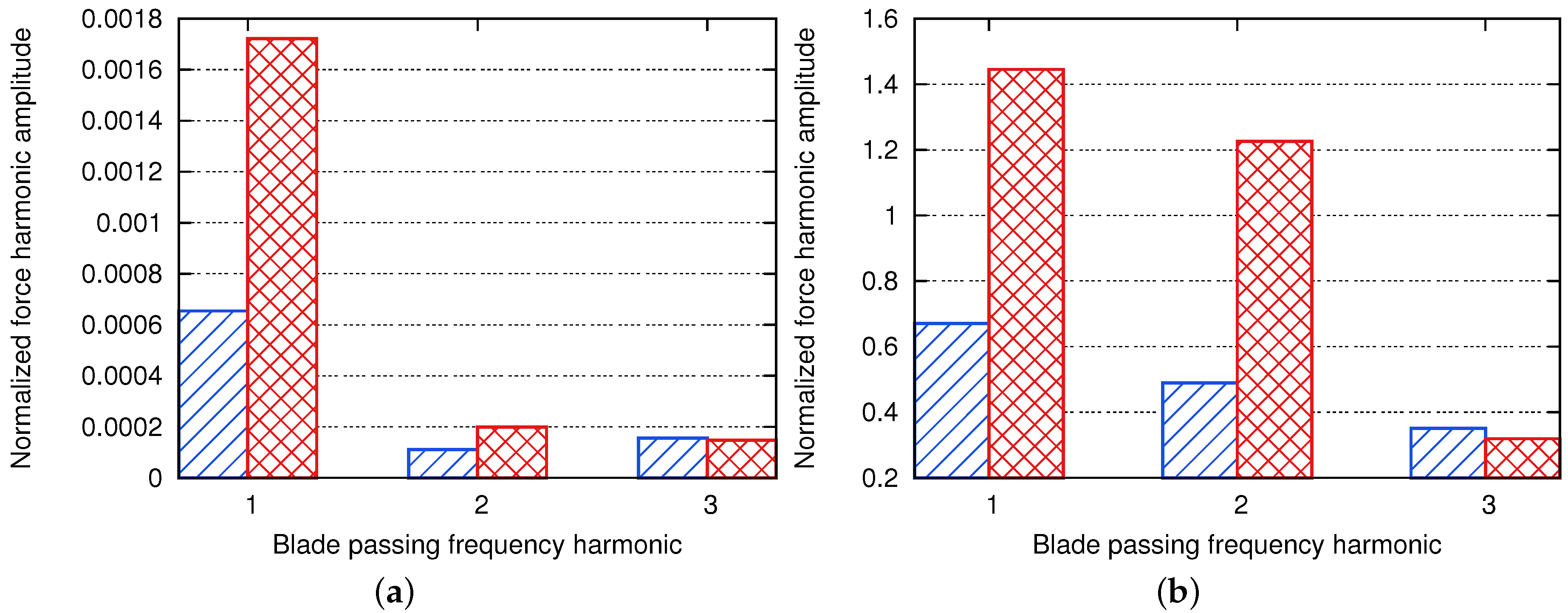
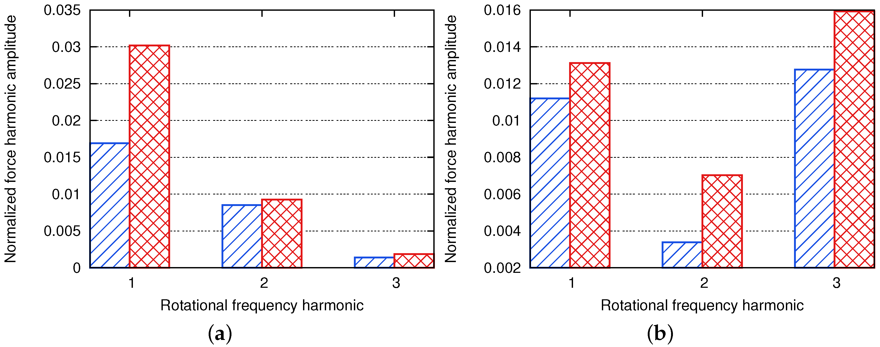
4.1.3. Impact of Air Inlet Distortion on the Harmonics of Fan-Blade Forces
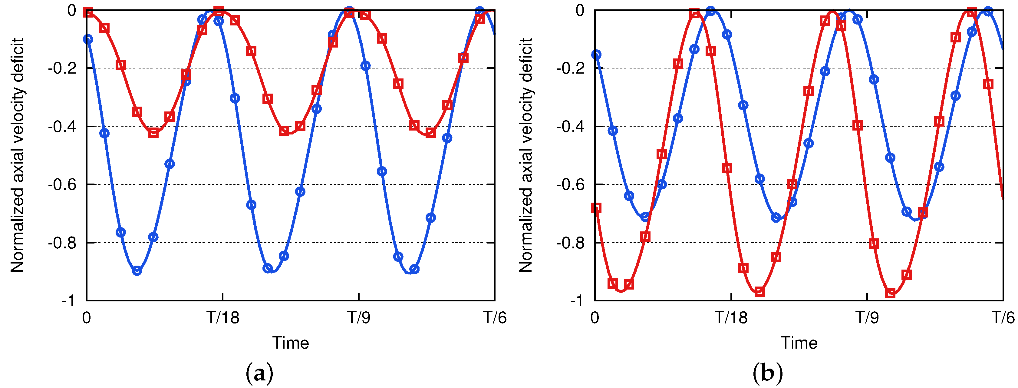
4.1.4. Impact of Air Inlet Distortion on Fan-Blade Wakes
4.1.5. Impact of Air Inlet Distortion on the Harmonics of OGV Forces
4.2. Acoustic Analysis
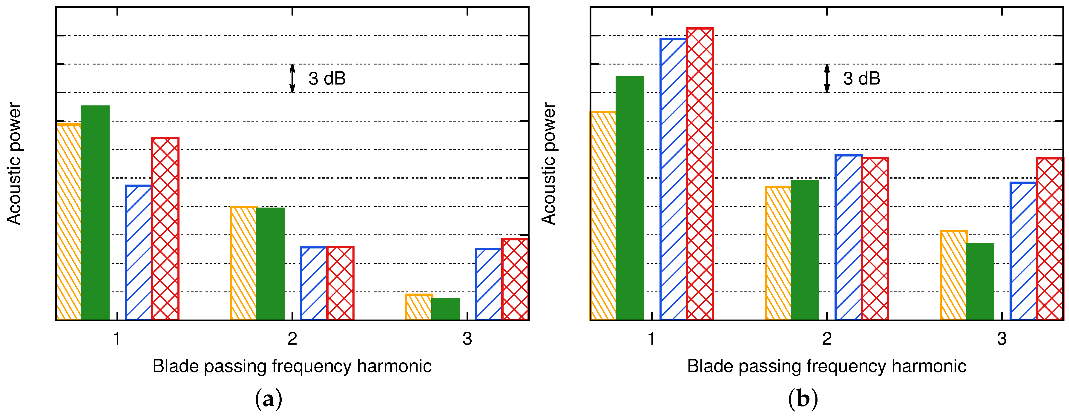
4.2.1. Source Breakdown
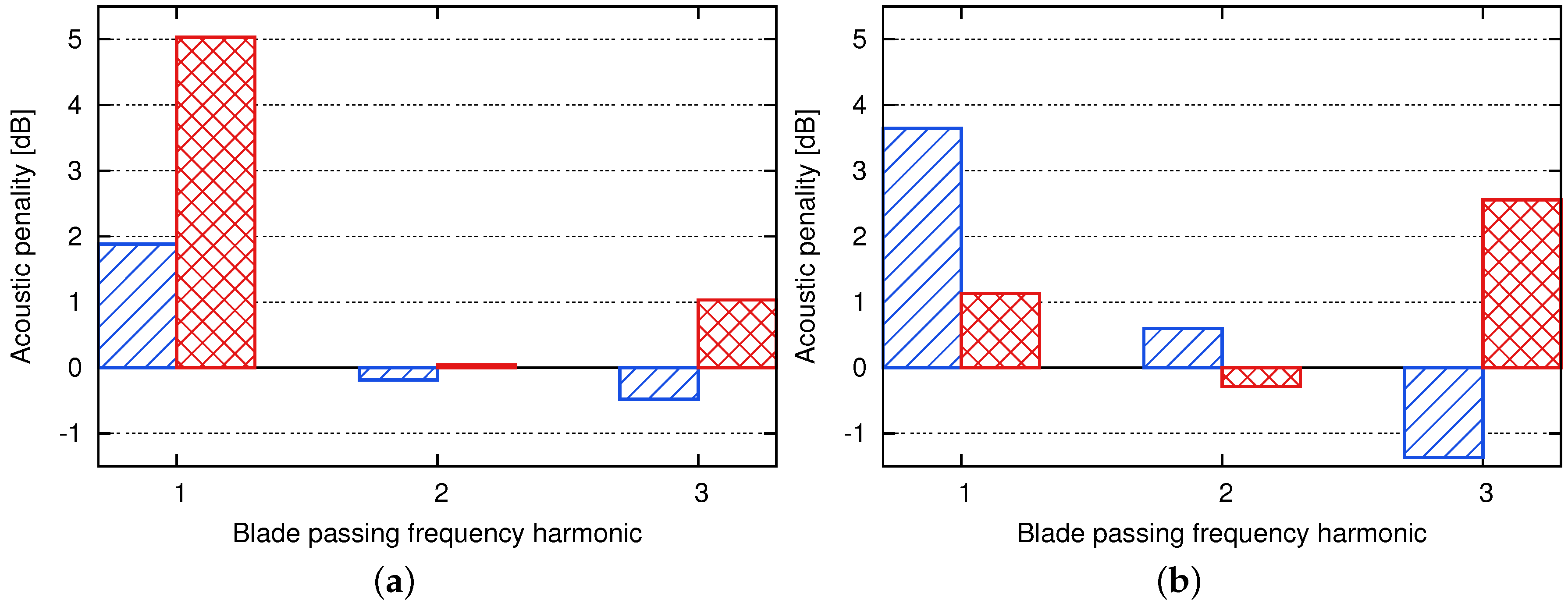
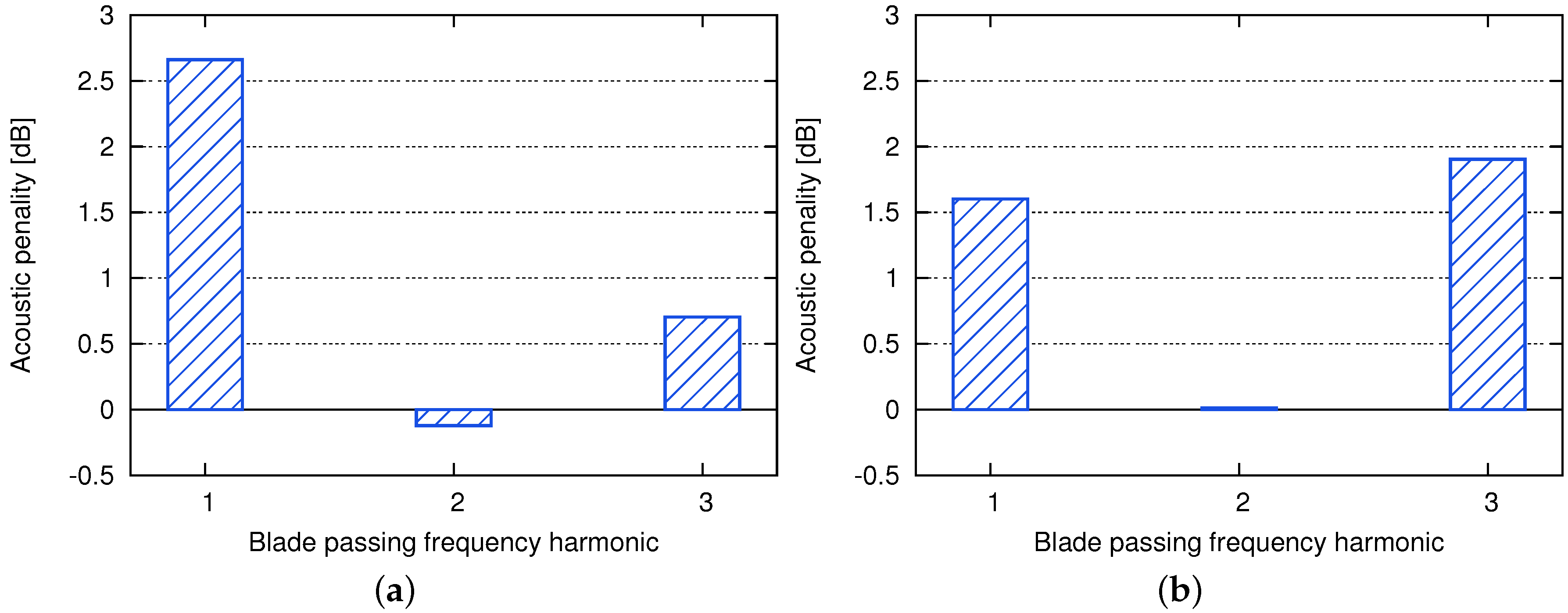
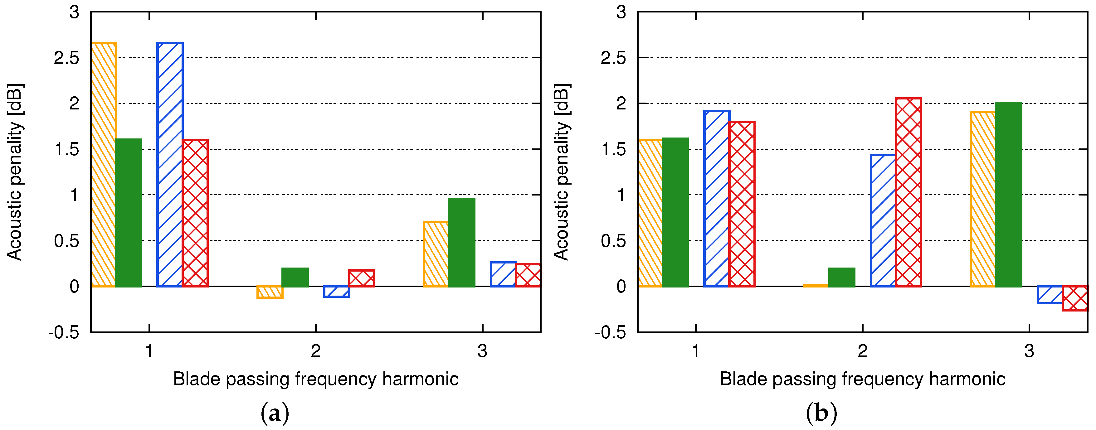
4.2.2. Acoustic Penalty Induced by the Air Inlet Distortion
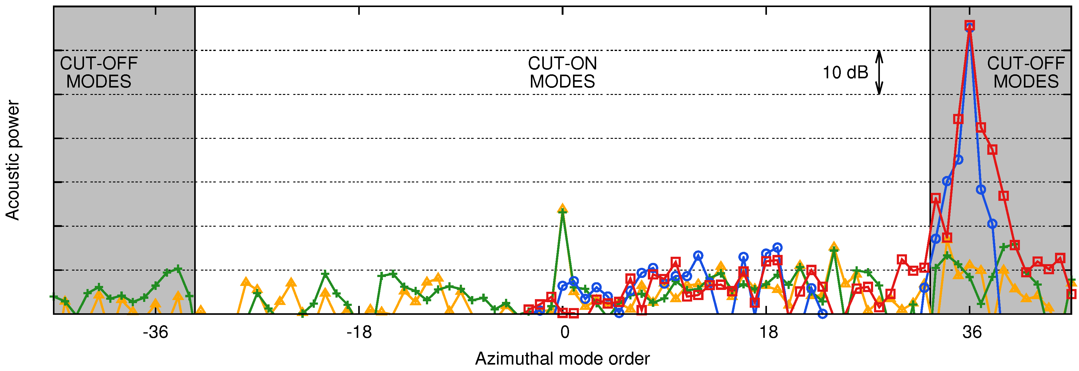
4.2.3. Modal Analysis
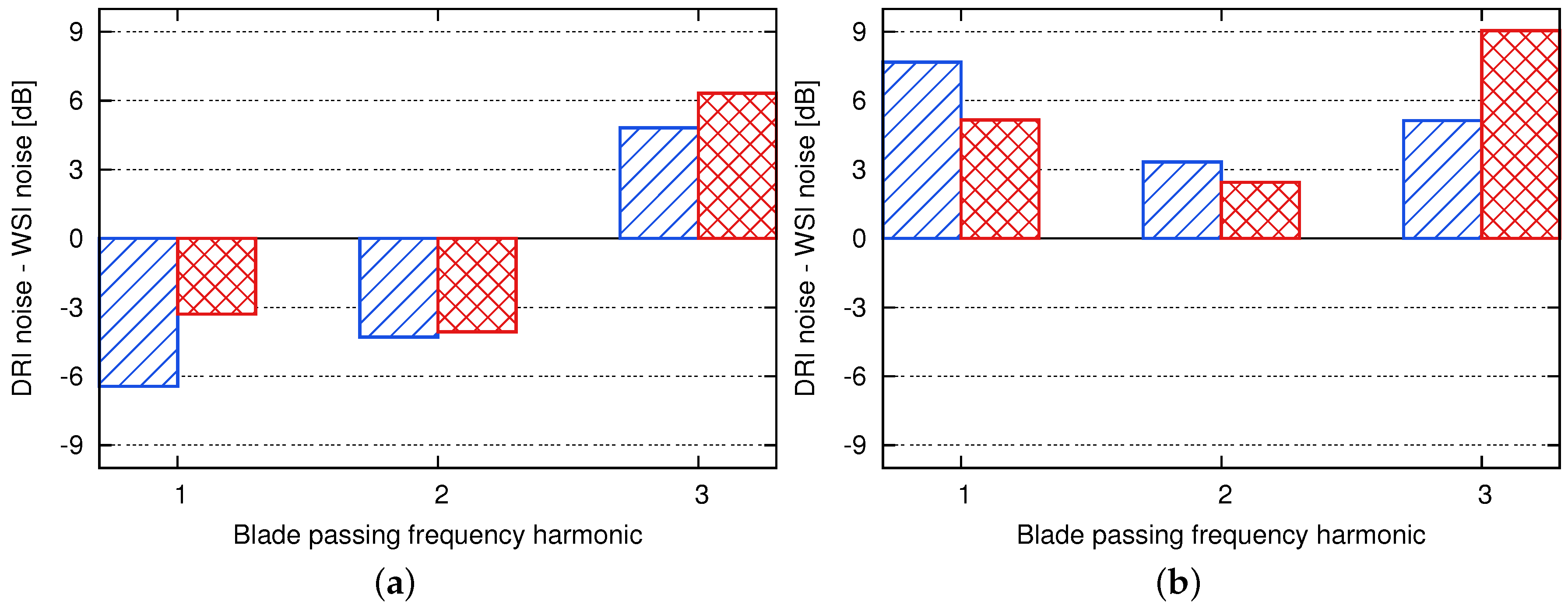
4.2.4. Robustness of the Method
- First set: The same ducts as the ones defined in Figure 7 are considered. Axisymmetric flow parameters are used for both the axisymmetric and asymmetric power estimates. This has the advantage of using the same cut-off criterion for both cases. This set corresponds to the results presented above.
- Second set: The same ducts as the ones defined in Figure 7 are considered. However, the axisymmetric flow parameters are used for the axisymmetric power estimate, and the asymmetric flow parameters are used for the asymmetric one. A maximum difference of 5% is obtained on the Mach number upstream of the fan.
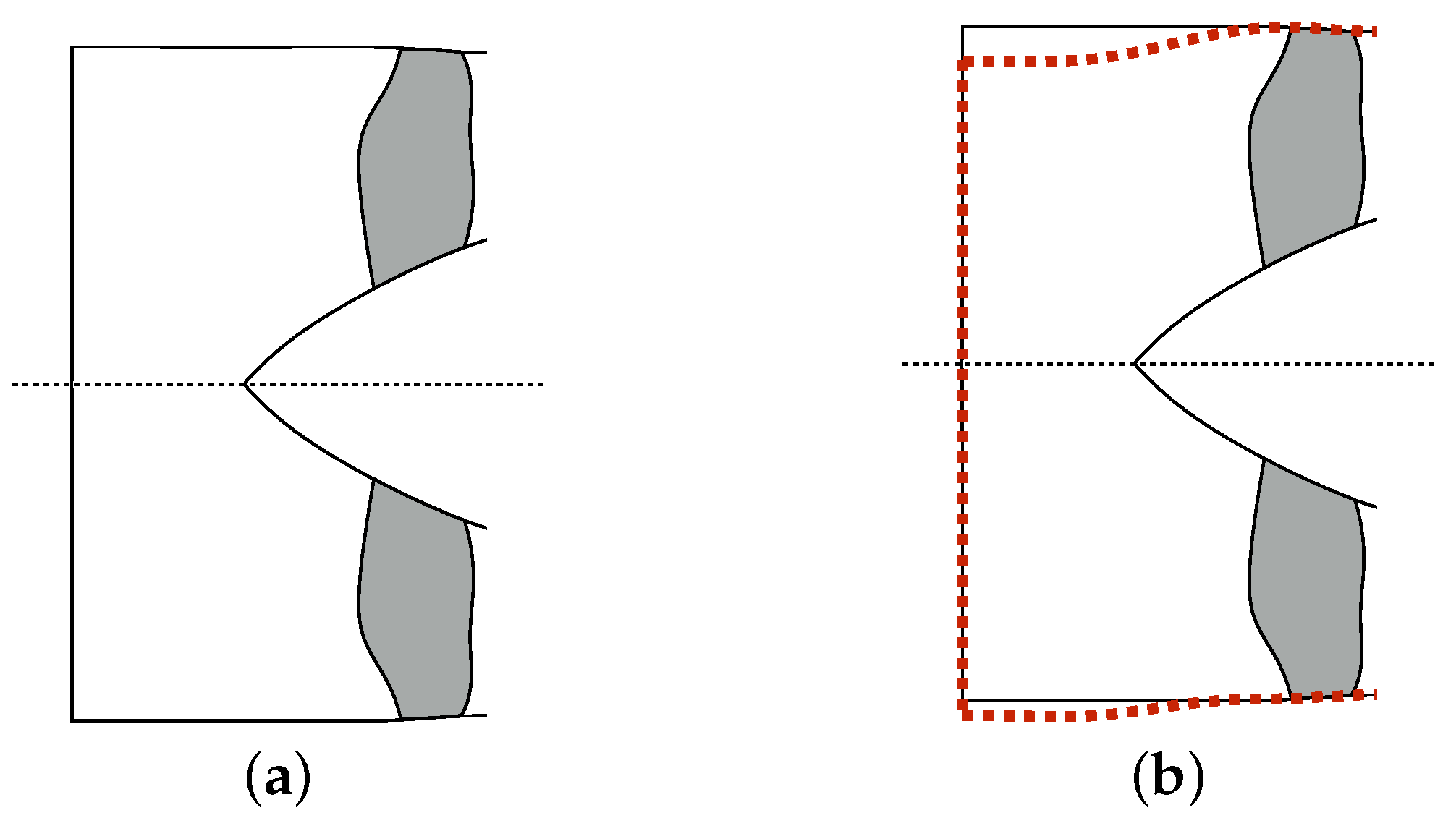
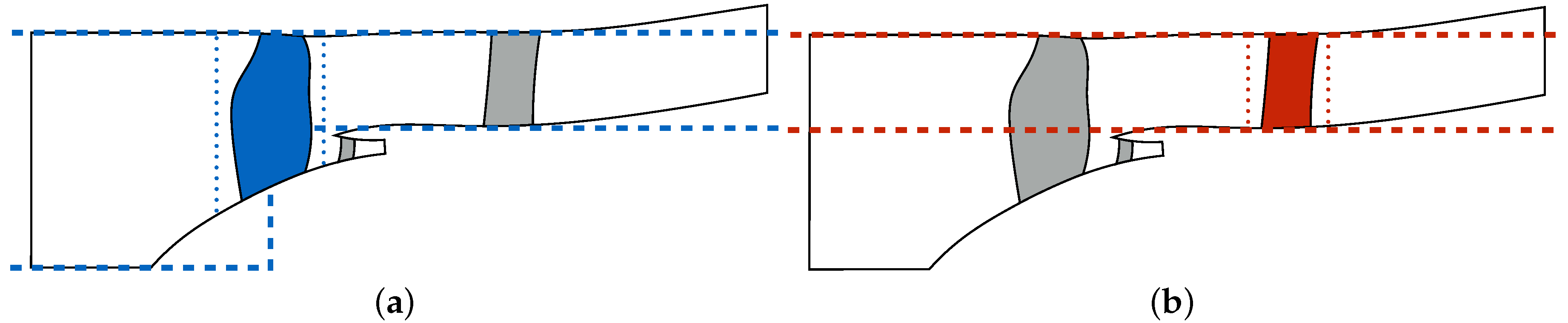
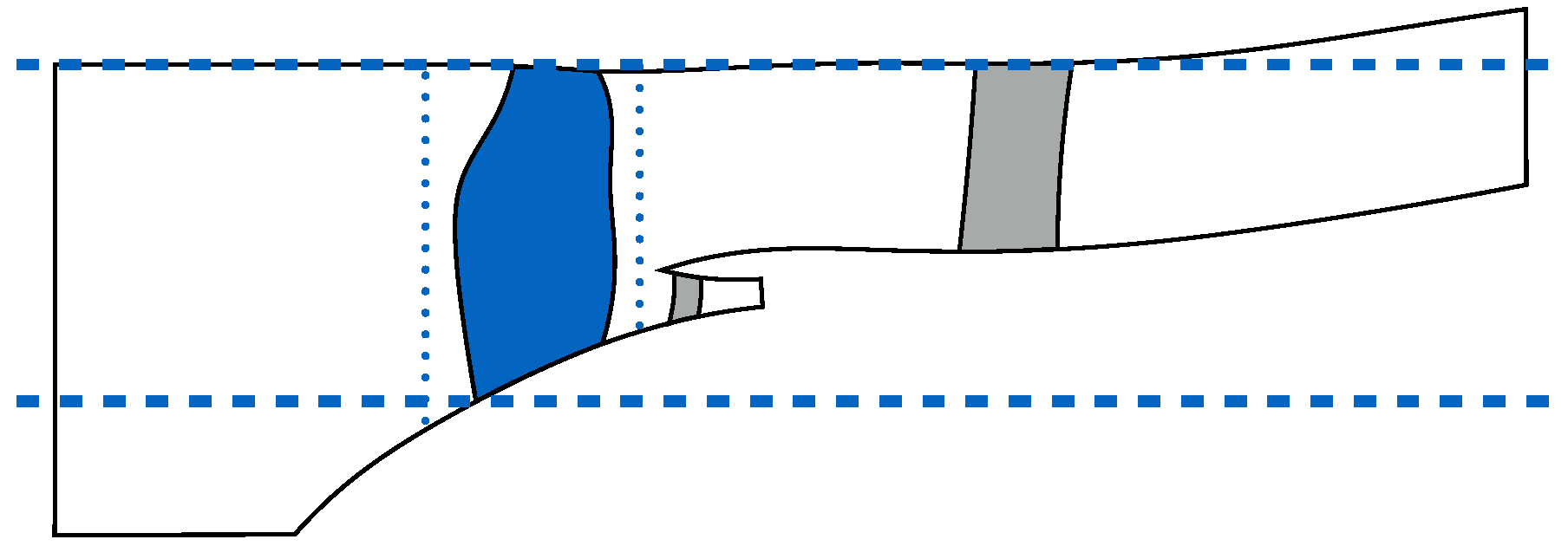
- Third set: For the OGV sources, the same duct as the one defined in Figure 7 is used. However, the duct used for the fan sources is modified. It now corresponds to the minimum and maximum radii of the fan blade. This new duct definition is represented by the blue horizontal lines in Figure 21. Similarly to the first set, axisymmetric flow parameters are used for both the axisymmetric and asymmetric power estimates. This again has the advantage of using the same cut-off criterion for both cases.
- Fourth set: The same ducts as the ones defined for the third set are used. However, similarly to the second set, the axisymmetric flow parameters are used for the axisymmetric power estimate, and the asymmetric flow parameters are used for the asymmetric one. A maximum difference of 5% is obtained on the Mach number upstream of the fan.
5. Discussion
Acknowledgments
Author Contributions
Conflicts of Interest
Abbreviations
| BPF | Blade Passing Frequency |
| CAA | Computational AeroAcoustics |
| CDC | Circumferential Distortion Coefficient |
| CFD | Computational Fluid Dynamics |
| DRI | Distortion-Rotor Interaction |
| IGV | Inlet Guide Vane |
| OGV | Outlet Guide Vane |
| RF | Rotational Frequency |
| UHBR | Ultra High Bypass Ratio |
| URANS | Unsteady Reynolds-Averaged Navier–Stokes |
| WSI | Wakes-Stator Interaction |
Nomenclature
| Latin Symbols | |
| First mode amplitude coefficient related to the mode | |
| B | Number of rotor blades |
| Second mode amplitude coefficient related to the mode | |
| Speed of sound of the uniform flow | |
| Local force on the fan blades or on the OGVs along the i-direction | |
| F | Integrated force on the fan blades or on the OGVs |
| Channel height ratio | |
| Bessel function of the first kind | |
| k | Any integer |
| Wavenumber of the uniform flow | |
| Modal coefficient related to the mode | |
| m | Azimuthal order of the mode |
| M | Mach number |
| Axial Mach number of the uniform flow | |
| n | BPF harmonic number |
| Normal vector to the wall | |
| p | Static pressure on the fan blades or on the OGVs |
| Acoustic power radiated upstream (+ sign) or downstream (− sign) | |
| Hub radius | |
| Tip radius | |
| S | Source surface |
| Source term related to the mode | |
| V | Number of stator vanes |
| Observer position in the fixed frame with the cylindrical coordinates (r, , x) | |
| Source position in the fixed frame with the cylindrical coordinates (, , y) | |
| Source position in the rotating frame with the cylindrical coordinates (, , y) | |
| Bessel function of the second kind | |
| Greek Symbols | |
| Compressibility factor of the uniform flow | |
| Axial wavenumber related to the mode | |
| Norm of the modal function related to the mode | |
| Duct eigenvalue related to the mode | |
| Radial order of the mode | |
| Density of the uniform flow | |
| Emission time | |
| Modal function related to the mode | |
| Pulsation | |
| Engine rotational speed | |
References
- Lighthill, M. On sound generated aerodynamically. I. General theory. Proc. R. Soc. A 1952, 211, 564–587. [Google Scholar] [CrossRef]
- Amiet, R.K. Acoustic radiation from an airfoil in a turbulent stream. J. Sound Vib. 1975, 41, 407–420. [Google Scholar] [CrossRef]
- Paterson, R.W.; Amiet, R.K. Acoustic Radiation and Surface Pressure Characteristics of an Airfoil Due to Incident Turbulence; Technical Report; National Aeronautics and Space Administration: Washington, DC, USA, 1976.
- Ventres, C.S.; Theobald, M.A.; Mark, W.D. Turbofan Noise Generation. Volume 1: Analysis; Technical Report; National Aeronautics and Space Administration Lewis Research Center: Cleveland, OH, USA, 1982.
- Glegg, S.A.L. The response of a swept blade row to a three-dimensional gust. J. Sound Vib. 1999, 227, 29–64. [Google Scholar] [CrossRef]
- Hanson, B. Theory for Broadband Noise of Rotor and Stator Cascades with Inhomogeneous Inflow Turbulence Including Effects of Lean and Sweep; Technical Report; National Aeronautics and Space Administration: Washington, DC, USA, 2001.
- Posson, H.; Roger, M.; Moreau, S. On a uniformly valid analytical rectilinear cascade response function. J. Fluid Mech. 2010, 663, 22–52. [Google Scholar] [CrossRef]
- Posson, H.; Moreau, S.; Roger, M. On the use of a uniformly valid analytical cascade response function for fan broadband noise predictions. J. Sound Vib. 2010, 329, 3721–3743. [Google Scholar] [CrossRef]
- De Laborderie, J.; Moreau, S. Evaluation of a Cascade-Based Acoustic Model for Fan Tonal Noise Prediction. AIAA J. 2014, 52, 2877–2890. [Google Scholar] [CrossRef]
- De Laborderie, J.; Blandeau, V.; Node-Langlois, T.; Moreau, S. Extension of a Fan Tonal Noise Cascade Model for Camber Effects. AIAA J. 2015, 53, 863–876. [Google Scholar] [CrossRef]
- De Laborderie, J.; Moreau, S. Prediction of tonal ducted fan noise. J. Sound Vib. 2016, 372, 105–132. [Google Scholar] [CrossRef]
- Goldstein, M. Aeroacoustics; McGraw-Hill Inc.: New York, NY, USA, 1976. [Google Scholar]
- Rienstra, S.W. Sound transmission in slowly varying circular and annular lined ducts with flow. J. Fluid Mech. 1999, 380, 279–296. [Google Scholar] [CrossRef]
- Ovenden, N.C. A uniformly valid multiple scales solution for cut-on cut-off transition of sound in flow ducts. J. Sound Vib. 2005, 286, 403–416. [Google Scholar] [CrossRef]
- Posson, H.; Peake, N. The acoustic analogy in an annular duct with swirling mean flow. J. Fluid Mech. 2013, 726, 439–475. [Google Scholar] [CrossRef]
- Matthews, J.; Peake, N. The acoustic Green’s function for swirling flow in a lined duct. J. Sound Vib. 2017, 395, 294–316. [Google Scholar] [CrossRef]
- Rumsey, C.L.; Biedron, R.T.; Farassat, F.; Spence, P.L. Ducted-fan engine acoustic predictions using a Navier–Stokes code. J. Sound Vib. 1998, 213, 643–664. [Google Scholar] [CrossRef]
- Bonneau, V.; Polacsek, C.; Barrier, R.; Lewy, S.; Roux, J.M.; Gervais, Y. Tonal Noise Prediction of a Turbofan with Heterogeneous Stator and Bifurcations. AIAA J. 2015, 53, 3354–3369. [Google Scholar] [CrossRef]
- Kopitz, J.; Bröcker, E.; Polifke, W. Characteristics-based filter for identification of planar acoustic waves in numerical simulation of turbulent compressible flow. In Proceedings of the 12th International Congress on Sound and Vibration, Lisbon, Portugal, 11–14 July 2005. [Google Scholar]
- Envia, E.; Wilson, A.; Huff, D. Fan Noise: A Challenge to CAA. Int. J. Comput. Fluid Dyn. 2004, 18, 471–480. [Google Scholar] [CrossRef]
- De Laborderie, J. Approches Analytiques et Numériques Pour la Prédiction du Bruit Tonal et Large Bande de Soufflantes de Turboréacteurs. Ph.D. Thesis, Université de Sherbrooke, Sherbrooke, QC, Canada, 2013. [Google Scholar]
- Holewa, A.; Weckmüller, C.; Guérin, S. Impact of Bypass Duct Bifurcations on Fan Noise. In Proceedings of the 18th AIAA/CEAS Aeroacoustics Conference, Colorado Springs, CO, USA, 4–6 June 2012. [Google Scholar]
- Bonneau, V. Prévision du Bruit D’interaction Tonal et à Large Bande D’une Soufflante de Nouvelle Génération en Régime Subsonique. Ph.D. Thesis, Université de Poitiers, Poitiers, France, 2015. [Google Scholar]
- Roger, M.; Caule, P. Assessment of the effect of stator inhomogeneity on rotor-stator tonal noise. In Proceedings of the 15th International Symposium on Transport Phenomena and Dynamics of Rotating Machinery, Honolulu, HI, USA, 10–15 April 2016. [Google Scholar]
- Tyler, J.; Sofrin, T. Axial flow compressor noise studies. Soc. Automot. Eng. Trans. 1962, 70, 309–332. [Google Scholar]
- Oishi, T.; Kusuda, S.; Kodama, H.; Namba, M.; Kazawa, J. Behaviors of Fan Tone Noise Under the Influence of Circumferentially Non-Uniform Steady Pressure Perturbation. In Proceedings of the 19th AIAA/CEAS Aeroacoustics Conference, Berlin, Germany, 27–29 May 2013. [Google Scholar]
- Sturm, M.; Sanjosé, M.; Moreau, S.; Carolus, T. Application of Analytical Noise Models Using Numerical and Experimental Fan Data. In Proceedings of the 11th European Conference on Turbomachinery, Fluid Dynamics and Thermodynamics, Jyvaskyla, Finland, 25–27 May 2015. [Google Scholar]
- Conte, F.; Roger, M.; Moreau, S.; Sanjosé, M.; Caule, P. Modeling of Installation Effects on the Noise from. In Proceedings of the 17th AIAA/CEAS Aeroacoustics Conference, Portland, OR, USA, 6–8 June 2011. [Google Scholar]
- Winkler, J.; Reimann, C.; Reba, R.; Gilson, J. Turbofan Inlet Distortion Noise Prediction with a Hybrid CFD-CAA Approach. In Proceedings of the 20th AIAA/CEAS Aeroacoustics Conference, Atlanta, GA, USA, 16–20 June 2014. [Google Scholar]
- Daroukh, M.; Moreau, S.; Gourdain, N.; Boussuge, J.F.; Sensiau, C. Influence of Distortion on Fan Tonal Noise. In Proceedings of the 22nd AIAA/CEAS Aeroacoustics Conference, Lyon, France, 30 May–1 June 2016. [Google Scholar]
- International Civil Aviation Organization. Annex 16 to the Convention on International Civil Aviation; International Civil Aviation Organization: Montreal, QC, Canada, 2005. [Google Scholar]
- Cambier, L.; Heib, S.; Plot, S. The Onera elsA CFD software: Input from research and feedback from industry. Mech. Ind. 2013, 14, 159–174. [Google Scholar] [CrossRef]
- Wilcox, D. Reassessment of the Scale-Determining Equation for Advanced Turbulence Models. AIAA J. 1988, 26, 1299–1310. [Google Scholar] [CrossRef]
- Zheng, X.; Liao, C.; Liu, C.; Sung, C.; Huang, T. Multigrid Computation of Incompressible Flows Using Two-Equation Turbulence Models: Part I—Numerical Method. J. Fluids Eng. 1997, 119, 893–899. [Google Scholar] [CrossRef]
- Sanjosé, M.; Daroukh, M.; De Laborderie, J.; Moreau, S.; Mann, A. Tonal noise prediction and validation on the ANCF rotor-stator configuration. Noise Control Eng. J. 2015, 63, 552–562. [Google Scholar] [CrossRef]
- Masson, V.; Posson, H.; Sanjosé, M.; Moreau, S.; Roger, M. Fan-OGV Interaction Broadband Noise Prediction in a Rigid Annular Duct with Swirling and Sheared Mean Flow. In Proceedings of the 22nd AIAA/CEAS Aeroacoustics Conference, Lyon, France, 30 May–1 June 2016. [Google Scholar]


© 2017 by the authors. Licensee MDPI, Basel, Switzerland. This article is an open access article distributed under the terms and conditions of the Creative Commons Attribution NonCommercial NoDerivatives (CC BY-NC-ND) license (https://creativecommons.org/licenses/by-nc-nd/4.0/).
Share and Cite
Daroukh, M.; Moreau, S.; Gourdain, N.; Boussuge, J.-F.; Sensiau, C. Effect of Distortion on Turbofan Tonal Noise at Cutback with Hybrid Methods. Int. J. Turbomach. Propuls. Power 2017, 2, 16. https://doi.org/10.3390/ijtpp2030016
Daroukh M, Moreau S, Gourdain N, Boussuge J-F, Sensiau C. Effect of Distortion on Turbofan Tonal Noise at Cutback with Hybrid Methods. International Journal of Turbomachinery, Propulsion and Power. 2017; 2(3):16. https://doi.org/10.3390/ijtpp2030016
Chicago/Turabian StyleDaroukh, Majd, Stéphane Moreau, Nicolas Gourdain, Jean-François Boussuge, and Claude Sensiau. 2017. "Effect of Distortion on Turbofan Tonal Noise at Cutback with Hybrid Methods" International Journal of Turbomachinery, Propulsion and Power 2, no. 3: 16. https://doi.org/10.3390/ijtpp2030016