Article

Numerical Investigation of Secondary Flow and Loss Development in a Low-Pressure Turbine Cascade with Divergent Endwalls †

Institute of Jet Propulsion, Bundeswehr University Munich, Werner-Heiseberg-Weg 39, 85577 Neubiberg, Germany
*
Authors to whom correspondence should be addressed.
This paper is an extended version of our paper published in Proceedings of the European Turbomachinery Conference ETC12 2017, Paper No. 335.
Int. J. Turbomach. Propuls. Power 2018, 3(1), 5; https://doi.org/10.3390/ijtpp3010005
Submission received: 7 December 2017 / Revised: 31 January 2018 / Accepted: 1 February 2018 / Published: 9 February 2018

Abstract

:
Secondary flow and loss development in the T106Div-EIZ low-pressure turbine cascade are investigated utilizing (U)RANS simulations in cases with and without periodically incoming wakes at M a 2 t h = 0.59 and R e 2 t h = 2 × 10 5 . The predictions are compared to experimental data presented by Kirik and Niehuis (2015). The axial mid-span and overall loss development in the T106Div-EIZ and the T106A-EIZ in the steady case are analyzed regarding the effects caused by the different loading distributions and by the divergent endwall geometry. Furthermore, the entropy generation is analyzed in the T106Div-EIZ with periodically incoming wakes in several axial positions of interest and compared to the undisturbed steady case. It is found that in the front-loaded T106Div-EIZ, the incoming wakes cause a premature endwall loss production in the front part of the passage, resulting in a lower intensity of the secondary flow downstream of the passage and a redistribution of the loss generation components.

1. Introduction

The trend of high-lift airfoils in modern low-pressure turbines of high-bypass jet engines has led to higher pressure gradients in the blade passages. In this context, secondary flow can be intensified and the corresponding losses increase. As alluded to in Denton’s [1] overview of the loss mechanisms in turbomachinery, it is evident that the secondary flows make a significant contribution to the overall losses, especially for low aspect ratio blades in which the secondary flows extend over a large portion of the blade span. In current axial turbines, secondary losses account for approximately 30 % of the overall losses (Cui and Tucker [2]). Whereas early studies on secondary flows and endwall losses focused on steady flow states, the loss development and unsteady interaction mechanisms in the endwall region are currently not understood in full detail. Thus, the influence of periodically incoming wakes on the endwall flow has been increasingly investigated in recent years.
Previous investigations of the endwall flow in the T106A-EIZ turbine cascade with parallel endwalls by Ciorciari et al. [3] have shown that periodically incoming wakes can influence the over- and under-turning in the secondary flow region depending on Strouhal number and flow coefficient. However, the influence of incoming wakes on the time-averaged endwall losses in the presented case was relatively small, which was confirmed by Koschichow et al. [4] utilizing incompressible direct numerical simulations (DNS) in a lower Reynolds number flow case. Similar conclusions were drawn by Volino et al. [5], who conducted measurements of unsteady secondary flows in a high-pressure turbine cascade, induced by upstream moving bars. The time-averaged total pressure losses exhibited very small differences between the cases with and without incoming wakes. In contrast to the relatively small effect of the incoming wakes, Volino et al. [6] described how the development of the endwall flow is greatly influenced by the inflow boundary layer.
Furthermore, an additional impacting factor on the loss development in modern turbines is the loading distribution of the airfoil. Wakelam et al. [7] investigated the profile losses in three different low-pressure turbine cascades with incoming wakes. The cascades had identical pitch, axial chord, inlet angle, and exit Mach number, but featured different airfoil designs. They highlighted the importance of blade loading distribution in regard to loss generation, particularly the maximum velocity location and diffusion on the suction surface. The ideal location of maximum velocity is dependent on wake passing frequency, diffusion factor, and Reynolds number. Muth and Niehuis [8] presented a method to deconstruct the integral loss of a low-pressure turbine cascade, enabling an analysis of profile loss components at low Reynolds numbers. Experimental data and predicted results from (U)RANS simulations were used to evaluate the axial loss development and to investigate the effect of incoming wakes among other influencing parameters. However, since the presented investigation was focused solely on mid-span profile and mixing losses, it did not cover the contribution of endwall losses. The relevance of loading distribution on full-span losses was investigated by Praisner et al. [9] on four aft- and front-loaded high-lift turbine airfoils. In terms of mid-span efficiency, the front-loaded designs showed great performance at low Reynolds numbers, essentially matching the low losses of the baseline design. However, an analysis of the full-span losses revealed a higher increase in endwall losses in the case of front-loaded airfoils with respect to designs that employ an aft-loaded approach. Weiss and Fottner [10] came to the same conclusion after investigating secondary flow and endwall losses in the aft-loaded T106 and the front-loaded T104 turbine cascades. Endwall loss generation and the effect of wake-disturbed inflow in the T106A turbine cascade have recently been investigated by Cui and Tucker [2]. Utilizing high fidelity eddy-resolving simulations, they identified two major regions of high loss generation rate: the corner vortex region and the interaction between the passage vortex and the blade suction surface.
The work presented in this paper combines multiple aspects of the aforementioned works in its investigation of the effects of periodically incoming wakes and blade loading distribution on loss generation in a turbine cascade. More precisely, the secondary flows and endwall losses in the T106Div-EIZ low-pressure turbine cascade are investigated in cases with and without periodically incoming wakes using computational fluid dynamics (CFD) predictions. In the T106Div-EIZ cascade, the divergent endwalls and the higher front-loading of the blades cause different inflow endwall boundary layer development and stronger secondary flows compared to the parallel endwall case under the same exit flow conditions, which has shown relatively weak secondary flows in previous investigations. The T106Div-EIZ cascade therefore provides a better basis for an analysis of the axial overall and endwall loss development throughout and downstream of the blade passage.

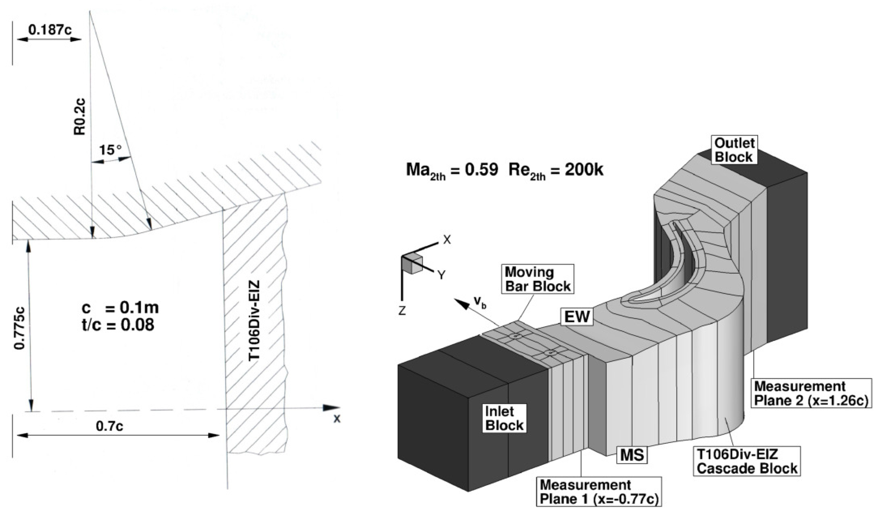
2. Experimental Reference Data

All experimental data presented in this paper was obtained in the High Speed Cascade Wind Tunnel of the Institute of Jet Propulsion of the University of the German Federal Armed Forces Munich (Universität der Bundeswehr München) and was published in detail by Kirik and Niehuis [11].

3. Investigated Test Cascade and Configurations

The investigated T106Div-EIZ turbine cascade consists of seven blades with a pitch to chord ratio of 0.8 featuring the aft-loaded T106 profile geometry investigated by Duden [12], Acton [13], and Stadtmüller [14]. The same airfoil has also been used in previous investigations of the T106A-EIZ cascade with parallel endwalls by Ciorciari et al. [3], where a new developing endwall boundary layer after the wake generator and upstream of the cascade was identified as the cause for the relatively weak secondary flows and the observed minor influence of the periodically incoming wakes in the endwall region. The T106D-EIZ cascade is equipped with straight divergent endwalls with an inclination of 15 with respect to the axial direction and an inflow aspect ratio of 1.55 ( c = 100 mm, H 1 = 155 mm). Under constant exit flow conditions, the flow in the T106Div-EIZ cascade induces a higher blade loading due to the divergent endwalls with respect to the T106A-EIZ cascade with an aspect ratio of 1.7 ( c = 100 mm, H = 170 mm) and parallel endwalls. In particular, the axial pressure distribution on the suction surface of the airfoil is altered, with the T106Div-EIZ exhibiting a higher loading in the front area. The higher front-loading in conjunction with the divergent endwall geometry cause different inlet endwall boundary layer development with the intention to produce more relevant secondary flows in the cascade and allow a better analysis of the effect of the incoming wakes on the endwall flow than in the parallel endwall case. Due to a constant exit Mach and Reynolds number in all configurations, the ratio of the mass flow rate in the T106Div-EIZ to the T106A-EIZ cascade is approximately 1.3.
In Figure 1, the geometry of the inlet region of the cascade is shown together with the modeled numerical multi-block domain. The investigated exit flow conditions M a 2 t h = 0.59 and R e 2 t h = 2 × 10 5 are defined by setting the total pressure and total temperature at the inlet as well as the static pressure downstream of the cascade, using the same fluid properties and constants as described in Ciorciari et al. [15].
Table 1 summarizes the investigated cases with and without periodically unsteady inflow. The denotation of the investigated cases is composed of the bar pitch t b in millimeters and bar speed v b in meters per second. The relatively high flow coefficients ϕ in the investigated cases are due to the realistic high speed inflow conditions featured in the experiment. In the experimental setup, the speed of the moving bars, which have a diameter of two millimeters, is limited due to mechanical safety concerns. However, CFD can be used in this context to extend the range of the investigated cases as published by Ciorciari et al. [15]. The unsteady T40 20 case is used for a comparison of the predicted results with the experimental data. Since the T80 20 case features a single bar wake in the computational domain, it is utilized for an analysis regarding the interaction of the incoming wakes with the secondary flow inside the passage and the axial loss development in the cascade. The inlet turbulence intensity value measured in the experiment in the wind tunnel at measurement plane 1, without a mounted wake generator, was of approximately 5 %.

4. CFD Setup

4.1. Flow Solver and Domain Discretization

The flow solver TRACE, developed by DLR Cologne (Institute of Propulsion Technology), has been used for all simulations presented in the present work. The code provides a numerical solution of the RANS equations using a finite volume approach. A detailed description of the implemented numerical methods and models can be found on the TRACE online portal by DLR [16] and in Eulitz [17], Yang et al. [18], Nürnberger [19], Kügeler [20], Yang et al. [21] and Becker [22]. In the present work, the RANS turbulent closure is modeled using the Wilcox k ω two-equation turbulence model, including the additional Kato and Launder pressure stagnation anomaly fix (Kato and Launder [23], Kozulovic et al. [24]). The transition model used in this work is the γ R e θ t transport equation model (Marciniak et al. [25], Menter and Langtry [26]).

4.2. Domain Definition and Boundary Conditions

Figure 1 shows the spanwise symmetrical 3D numerical domain which is used for all simulations of the T106Div-EIZ. A high boundary layer resolution is assured by a fine OC-Grid with y + 1 on the viscous blade walls. The entire domain includes a total number of around 4.7 million grid cells. For the temporal resolution in the unsteady simulations, the number of time steps per moving domain period is set to 1200, which enables a resolution of the moving bar vortex shedding frequency. In order to ensure sufficient periodic convergence, the unsteady simulations are run for 15 moving domain passing periods. Additional blocks are added at the domain inlet and outlet. The non-divergent outlet block, which features an inviscid endwall, is implemented to assure an adequate setting of the static outlet pressure as a non-reflecting boundary condition in a radial equilibrium state. In the steady cascade investigations, the sensitivity of the variation of the inlet flow angle β 1 s t e a d y has been evaluated starting from the design angle ( β 1 d e s i g n = 127.7 ). A pressure-sided incidence angle of 1 resulted in an improved prediction of the experimental isentropic Mach number distribution at mid-span as seen in Figure 2 and is therefore used for all unsteady calculations in the plane upstream of the wake generator ( β 0 = β 1 s t e a d y = 128.7 ). The predicted results of the T106A-EIZ are obtained using an inlet flow angle of β 0 = 129.7 (Ciorciari et al. [3]).

5. Results

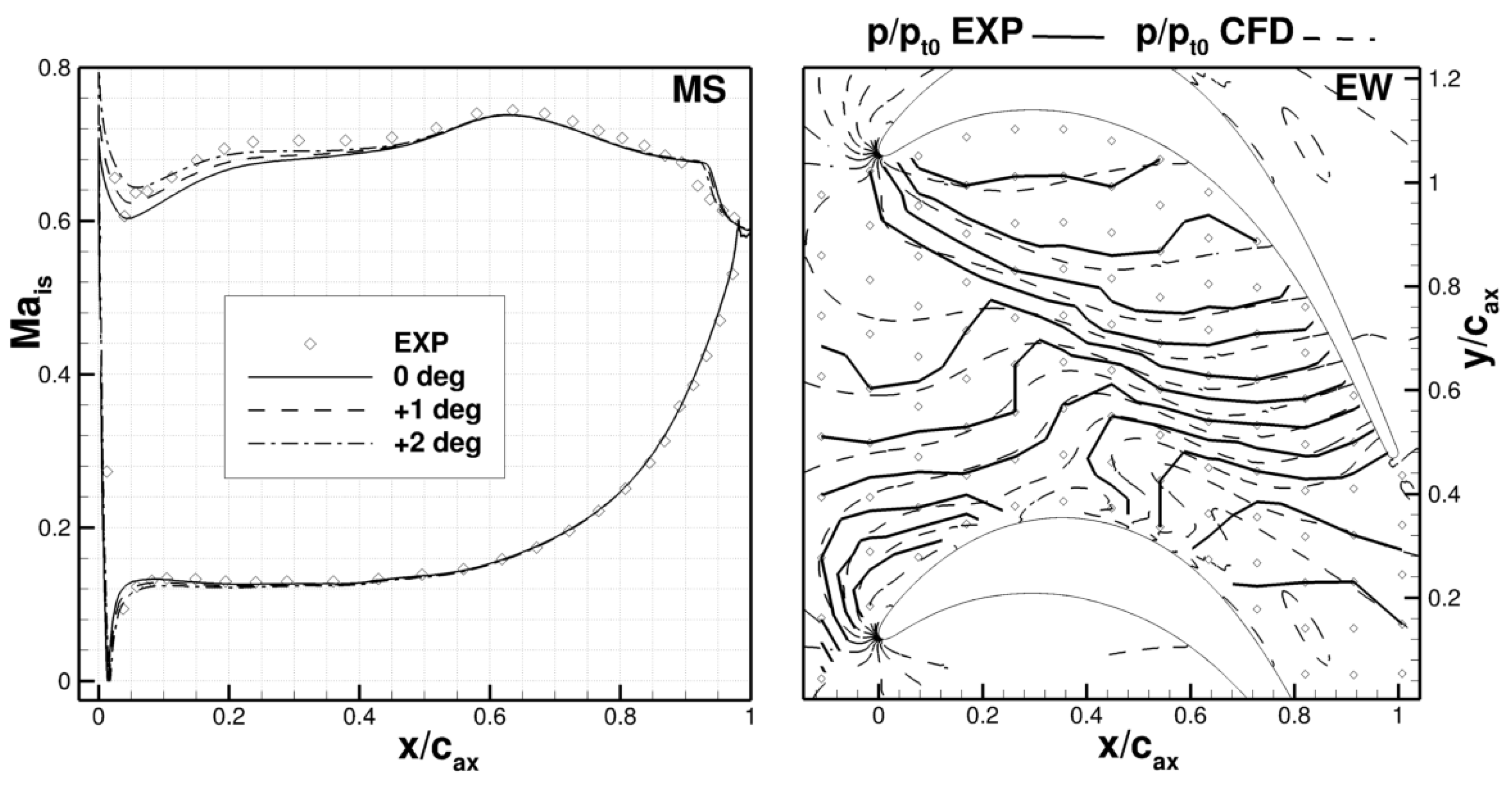
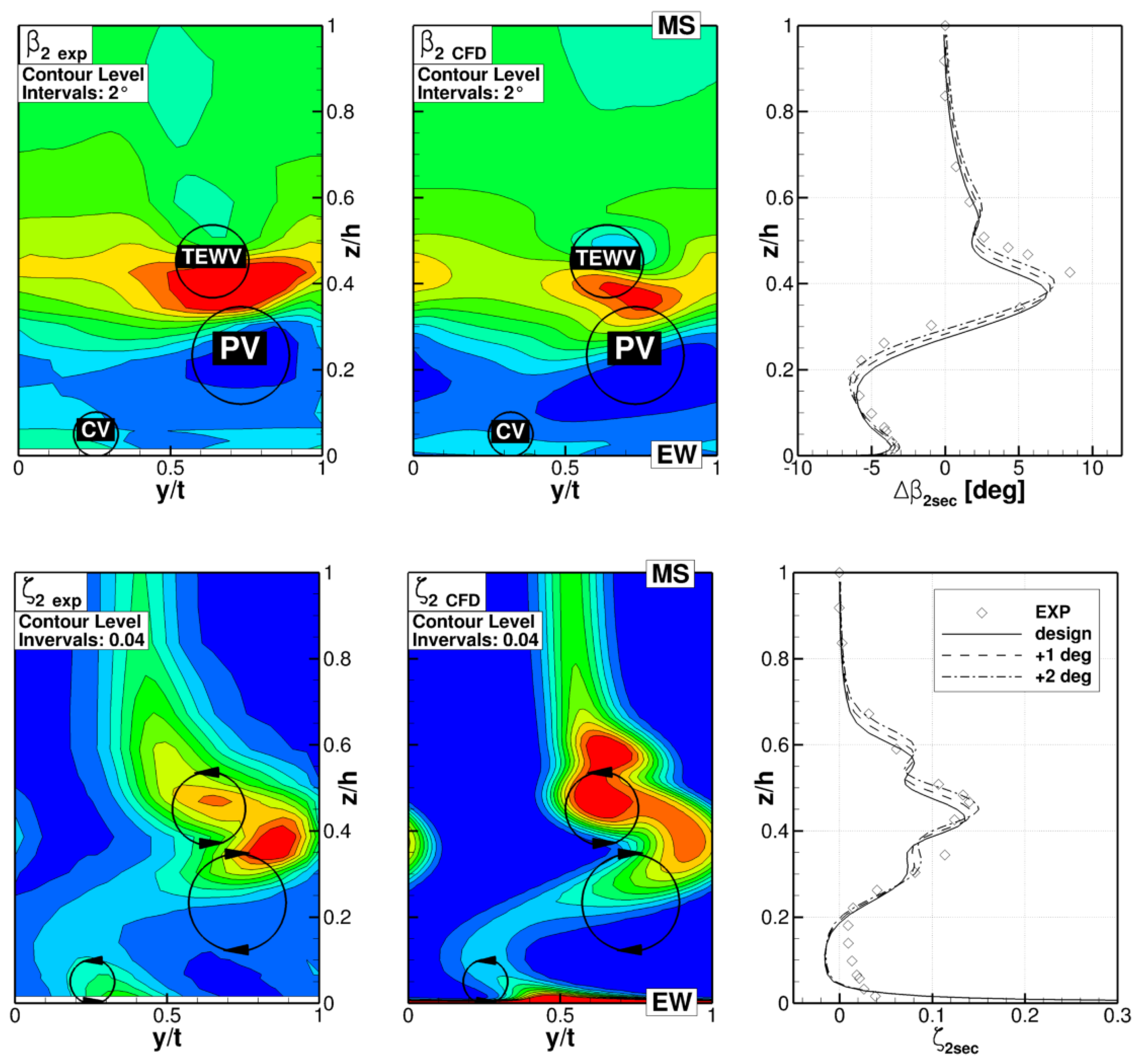
5.1. Comparison with Measured Data

On the left-hand side of Figure 2, the comparison between the predicted isentropic Mach number distributions at mid-span in the T106Div-EIZ at M a 2 t h = 0.59 and R e 2 t h = 200 k with the measured data shows a good agreement. The larger extension of the separation bubble in the prediction is attributed to a quicker turbulence decay in the numerical domain, resulting in a lower free-stream turbulence intensity with respect to the experiment. The turbulence decay and the propagation of flow properties throughout the computational domain are influenced by the choice of turbulence model as well as the grid resolution in (U)RANS simulations. However, the laminar boundary layer on the suction surface upstream of the separation bubble appears well modeled using the turbulent length scale of the order of 1 %, and the resulting profile losses match well with the downstream measured values. On the right-hand side of Figure 2, the measured isobar distribution on the endwall shows a stronger distortion of the isobars at the inlet of the passage with respect to the simulations. This appears to be caused by an earlier roll-up of the inlet endwall boundary layer in the experiment. The difference with respect to the predicted values is related to uncertainties regarding the modeling of the inlet endwall boundary conditions due to the mounted wake generator in the experimental setup and the upstream effect of the endwall divergence. The earlier roll-up of the inlet boundary layer results in a more intense passage vortex (PV) and causes higher total pressure loss values ζ 2 e x p with respect to ζ 2 C F D in the vortex interaction region near z / h = 0.4 shown on the bottom of Figure 3. The experimental Δ β 2 s e c values at the top of Figure 3 confirm this observation, indicating a higher underturning with respect to the predictions. Furthermore, the higher lift-off of the passage vortex in the experiment is partially attributed to the earlier roll-up of the inlet endwall boundary layer. It also appears that the more intense trailing edge wake vortex (TEWV) in the CFD ( 0.4 < z / h < 0.5 ) is constraining the lift-off of the passage vortex. The higher intensity of the predicted TEWV is attributed to the aforementioned longer separation bubble simulated on the suction side and the lower free-stream turbulence intensity. Additionally, the linear eddy viscosity model used in all simulations, in which the Boussinesq approximation is adopted, works under the assumption of isotropic turbulence. As observed by Michelassi et al. [27] and Pichler et al. [28] in DNS studies of mid-span flow in the T106A cascade, the linear stress–strain coupling is error-inducing in regions where significant anisotropic stress is present. Considering that anisotropic stress is highly relevant in the investigated secondary flow region with complex vortex interaction, the underlying limitations of the chosen turbulence model present an uncertainty in the flow predictions and may contribute to the observed differences in the experimental data.

5.2. Steady Numerical Analysis

The previous results highlight the influence of the inlet endwall boundary layer development on the secondary flows in and downstream of the passage. The development of the inlet boundary layer, in turn, is directly related to the pressure field upstream of the cascade. In the T106Div-EIZ, the presence of the endwall divergence induces a spanwise pressure gradient and different diffusion properties with respect to the parallel endwall case. A comparison of the velocity v / v 1 and total pressure p t / p t 0 profiles perpendicular to the endwall upstream of the T106Div-EIZ for two pitchwise positions, in Figure 4, is useful to gain a better understanding of the inlet endwall boundary layer development considering its three-dimensional characteristics. The strings of perpendicular lines are defined starting at the two pitchwise positions at x w = 0.06 and respectively following a theoretical streamline with the given design inflow angle. The first streamline shown at the top of Figure 4 passes through the center of the passage and the second streamline is designed to impinge near the leading edge of the blade. After the EIZ gap, a new boundary layer is developing and overlapping with the spanwise non-uniformly accelerated flow near the beginning of the endwall divergence, which is evident at x w = 0.06 and x w = 0.036 . The local acceleration is a result of the flow following the endwall curvature, which induces a spanwise pressure gradient in a radial equilibrium state. At these axial positions, the v / v 1 and p t / p t 0 profiles at both pitchwise positions are very similar, indicating that the potential effect of the downstream airfoils is negligible at that distance. At the axial positions x w = 0.027 and x w = 0.017 , the potential effect of the airfoil on the incoming endwall flow is visible considering the differences shown in the v / v 1 profiles in the two pitchwise positions. However, the p t / p t 0 profiles are similar at both pitchwise positions.
The mass flow-averaged overall axial total pressure loss Δ p ( t 1 t x ) / q 2 t h developments throughout the T106Div-EIZ and the T106A-EIZ in Figure 5 confirm an alteration of the endwall boundary layer loss development at around x / c a x = 0.6 , not related to the increased frontal loading, but rather to the start of endwall divergence. In front of the leading edge ( x / c a x = 0 ), the endwall boundary layer losses in the T106Div-EIZ are higher than those in the T106A-EIZ; however, at mid-span, no significant free stream losses are produced in both cases. Approaching the leading edge, the mid-span profile losses are higher in the T106Div-EIZ with respect to the T106A-EIZ considering the higher front-loading, inflow velocity, and shear stress. Due to the higher frontal loading, the position of the separation/transition region on the suction side in the T106Div-EIZ is located further upstream than in the T106A-EIZ. An apparent convergence of the values occurs near the trailing edge before the T106Div-EIZ finally produces higher profile losses downstream of the trailing edge ( x / c a x > 1 ). The differences in mid-span total loss production in the two cascades are relatively small compared to the differences observed in the secondary flow region in Figure 5. The different development of the inlet endwall boundary layer effectively causes a stronger endwall boundary layer vorticity at the inlet of the cascade in the case of the T106Div-EIZ. The higher endwall losses observed in the T106Div-EIZ are mainly attributed to the higher momentum deficiency in the incoming endwall boundary layer, but also partially to the longer wetted shear surface due to the divergence and the stronger front-loading of the cascade with respect to the T106A-EIZ. In a front-loaded cascade, high transverse pressure gradients act on the relatively thick boundary layer in the front section of the passage, resulting in a stronger passage vortex. The dissipation of the kinetic energy of the vortex motion causes higher endwall losses in the aft section and downstream of the passage. On the contrary, the maximum pressure gradient in the aft-loaded T106A-EIZ does not occur until further downstream, where the endwall boundary layer is much thinner and weaker secondary flow ensues. Aside from the different overall loss levels, the loss developments far downstream of the trailing edge in Figure 5 show a similar behavior in both cascades. Following the mixing loss region, which extends to approximately x / c a x = 1.3 , there is a quasi-linear loss increase as a result of the endwall flow in this region. This observation is consistent with the findings published by Muth and Niehuis [8], which showed a rapid increase in mixing losses near the trailing edge, especially at low Reynolds numbers, followed by a decreased loss gradient once the flow is mixed out.

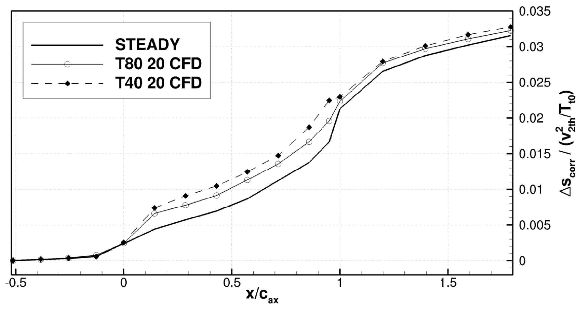
5.3. Steady and Unsteady Comparison

In order to obtain a better understanding of the loss production mechanisms due to periodically incoming wakes and their interaction with the secondary flows, the overall entropy generation in the T106Div-EIZ is presented in Figure 6. Considering the relatively weak secondary flows in the T106A-EIZ as well as the relatively minor effects due to the incoming wakes, only the T106Div-EIZ is analyzed. As mentioned before, the unsteady simulations were conducted using a high temporal and spatial resolution. Therefore, the change over time in the computational domain shows two main signals, the periodical inflow disturbance as well as the superimposed fluctuations of the vortex shedding in the bar wakes featuring distinctly different frequencies and amplitudes. The periodical inflow disturbance appears to be well reproduced in the numerical simulations of the investigated cases, whereas the amplitude of the vortex shedding is afflicted with numerical uncertainties considering the limitations of the (U)RANS approach and the linear eddy viscosity model. Resolving the vortex shedding in the numerical simulation leads to an energy separation phenomenon as observed by Adami et al. [29], which implies that in this region both total pressure and total temperature variations have to be considered collectively in order to evaluate overall losses in the domain. The predicted non-dimensional entropy generation Δ s / ( v 2 t h 2 / T t 0 ) for the undisturbed, the T80 20 and the T40 20 cases was calculated by
Δ s ( x ) v 2 t h 2 / T t 0 = c v l n p t ( x ) p t , 0 + c p l n ρ t ( x ) ρ t , 0 v 2 t h 2 / T t 0 .
The reference total temperature and total pressure values as well as the fluid properties are defined by the inlet conditions of the calculation. For the evaluation of the axial entropy development, the local values are interpolated from the numerical grid onto a defined structured grid utilizing inverse distance weighting at each respective axial position. Subsequently, the mass flow weighted average is calculated. The structured uniform grid for the interpolation was defined in three regions, x / c a x < 0 , 0 < x / c a x < 1 , and x / c a x > 1 featuring different resolutions, 90 × 100 , 100 × 100 and 200 × 200 node elements respectively. These grid resolutions are obtained through a grid sensitivity analysis and are also used for the evaluation of Δ p ( t 1 t x ) / q 2 t h in the T106Div-EIZ in Figure 5. The ratio of grid nodes of the interpolation grid to the non-uniform numerical grid is approximately 1.1 in the domain section of the blade passage ( 0 < x / c a x < 1 ) . For the T106A-EIZ configuration, a smaller resolution ( 100 × 100 ) is sufficient in the region x / c a x > 1 downstream of the trailing edge considering the constant span height in this case.
The overall corrected entropy value Δ s c o r r / ( v 2 t h 2 / T t 0 ) = [ Δ s ( x ) Δ s ( x r e f ) ] / ( v 2 t h 2 / T t 0 ) is defined in order to filter the incoming wake losses at the cascade inlet in Figure 6 and thus allow a separate analysis of the effect of the incoming wakes on the entropy development throughout the cascade ( x / c a x > x r e f / c a x = 0.6 ), with x / c a x = 0 at the airfoil leading edge. In front of the leading edge, the differences in Δ s c o r r / ( v 2 t h 2 / T t 0 ) between the undisturbed and the two unsteady cases appear to be negligible with respect to the values inside and downstream of the passage. Entering the blade passage 0 < x / c a x < 1 , a relevant divergence of the entropy generation lines is apparent, where a stronger entropy increase is observed in the cases of disturbed inflow with respect to the steady case. At the trailing edge and downstream, the entropy generation lines are converging again, which will be explained with the help of Figure 7. The overall higher losses produced in the passage in the two cases with incoming wakes are attributed to the bar wake interaction with the endwall flow and with the airfoil boundary layer. The bar wake mixing losses, however, are considered to be negligible in the passage region with respect to the aforementioned factors. In Figure 7, the comparison of time-averaged entropy values in different axial slices illustrates the effect of the incoming wakes in the T80 20 case with respect to the steady case. The time-averaged values result from an arithmetic averaging of 120 flow solutions out of the overall 1200 time-steps calculated in one bar passing period of the unsteady simulation. The roll-up of the passage vortex and the pressure-driven transport towards the suction surface is delayed by the interaction with the incoming wakes, causing a less distinct system of secondary vortices with respect to the undisturbed case in this front-loaded configuration. This mechanism is correlated to a premature loss production as seen at about x / c a x = 0.1 in Figure 6. Furthermore, a smaller lift-off of the passage vortex and a homogenizing effect in terms of under- and over-turning is apparent in the predicted results, which is consistent with the experimental data presented by Kirik and Niehuis [11]. The weaker passage vortex is transported downstream with lower streamwise vorticity, which results in smaller secondary loss production near the trailing edge and mixing losses in the downstream flow field, causing the aforementioned convergence of the entropy generation lines in Figure 6. In the investigated case at R e 2 t h = 2 × 10 5 , the profile losses in the unsteady cases are augmented with respect to the steady case due to the interaction of the incoming wakes with the profile boundary layer. More precisely, the periodically incoming wakes cause the transition/separation region to move further upstream on the suction surface, resulting in a longer reattached turbulent boundary layer and therefore higher profile losses. The contribution of the profile losses appears to be a relevant cause of the higher Δ s c o r r / ( v 2 t h 2 / T t 0 ) values observed downstream of the cascade in the unsteady cases. The first divergence of the entropy generation lines near the leading edge in conjunction with the convergence near the trailing edge in Figure 6 confirm the redistribution of the loss components in the passage due to the incoming wakes. The incoming wakes reduce the intensity of the secondary flows in and downstream of the passage, but the reduction appears to be insufficient to compensate for the augmented profile losses.

6. Conclusions

Steady and unsteady numerical analyses were conducted in order to investigate the effect of periodically incoming wakes on the axial loss development throughout the T106Div-EIZ turbine cascade. The comparison with experimental data at mid-span, near the endwall, and downstream of the cascade provides a verification of the predicted results. Some differences with respect to the measured data are attributed to uncertainties related to the inlet flow conditions of the investigated cascade and to the turbulence/transition modeling of the (U)RANS approach. Nevertheless, the main flow phenomena are well reproduced and allow an analysis of the effect of the incoming wakes on the flow into and downstream of the passage. A comparison between the T106Div-EIZ and the T106A-EIZ with parallel endwalls under the same exit flow conditions indicates that the T106Div-EIZ produces more intense secondary flows in the passage. This is caused not only by the higher front-loading, but also by the endwall geometry, which influence the roll-up of the incoming endwall boundary layer and the axial loss development in front of the cascade. The overall loss development indicates that the increased values in the case of divergent endwalls are mainly related to the endwall flow. A comparison of the steady and unsteady cases at M a 2 t h = 0.59 and R e 2 t h = 2 × 10 5 shows a redistribution of the loss generation components due to the incoming bar wakes. In the front-loaded T106Div-EIZ, the incoming wakes cause a premature endwall loss production in the front part of the passage resulting in a lower intensity of the secondary flow downstream of the trailing edge and smaller secondary mixing losses. Nevertheless, in the investigated cases, the profile losses are augmented by an earlier transition/separation and a longer reattached turbulent boundary layer due to the incoming wakes, causing an increased overall entropy generation with respect to the undisturbed case.

Acknowledgments

The investigations were conducted as part of the Deutsche Forschungsgemeinschaft joint research project PAK-530. The authors acknowledge Ilker Kirik, who carried out the experimental measurement campaign and Alexander Jörger for his contribution to the post processing. Furthermore, the authors wish to acknowledge DLR Cologne, Institute of Propulsion Technology, for provision of the flow solver TRACE and for the very productive collaboration.

Author Contributions

The presented work stems from a joint research effort of Roberto Ciorciari and Tobias Schubert, including data acquisition, post-processing, analysis and paper writing, resulting in equal contributions to the paper. As the head of the Institute of Jet Propulsion Reinhard Niehuis was responsible for the supervision of all research activities associated with the presented work.

Conflicts of Interest

The authors declare no conflict of interest. The founding sponsors had no role in the design of the study; in the collection, analyses, or interpretation of data; in the writing of the manuscript, and in the decision to publish the results.

Nomenclature

Latin Symbols
cchord length
H, hheight in spanwise direction, h = 1 / 2 · H
MaMach number
ppressure
qdynamic pressure
ReReynolds number
sentropy
SrStrouhal number, ( v b / t b ) · ( c / v a x , 0 )
Ttemperature
tpitch
vvelocity
xaxial coordinate
ypitch-wise coordinate
zspan-wise coordinate
Greek Symbols
β yaw (pitch-wise) angle
Δ p t / q 2 t h total pressure losses
Δ s entropy generation
ϕ flow coefficient, v a x / v b
Abbreviations
CFDComputational Fluid Dynamics
CVCorner Vortex
DNSDirect Numerical Simulation
EIZErzeuger Instationärer Zuströmung
(wake generator)
EWEndWall
EXPExperimental
LPTLow-Pressure Turbine
MSMid-Span
PVPassage Vortex
TEWVTrailing Edge Wake Vortex
(U)RANS(Unsteady) Reynolds-Averaged Navier-Stokes equations
Subscripts
0domain inlet
1,2measurement planes
axaxial
bbar
corrcorrected
ttotal
ththeoretical
secsecondary

References

  1. Denton, J.D. The 1993 IGTI Scholar Lecture: Loss Mechanisms in Turbomachines. J. Turbomach. 1993, 115, 621–656. [Google Scholar] [CrossRef]
  2. Cui, J.; Tucker, P.G. Numerical Study of Purge and Secondary Flows in a Low Pressure Turbine. J. Turbomach. 2017, 139, 021007. [Google Scholar] [CrossRef]
  3. Ciorciari, R.; Kirik, I.; Niehuis, R. Effects of Unsteady Wakes on the Secondary Flows in the Linear T106 Turbine Cascade. J. Turbomach. 2014, 136, 091010. [Google Scholar] [CrossRef]
  4. Koschichow, D.; Fröhlich, J.; Kirik, I.; Niehuis, R. DNS of the Flow Near the Endwall in a Linear Low Pressure Turbine Cascade with Periodically Passing Wakes. In Proceedings of the ASME Turbo Expo 2014: Turbine Technical Conference and Exposition, Düsseldorf, Germany, 16–20 June 2014. Paper No. GT2014-25071. [Google Scholar]
  5. Volino, R.; Galvin, C.D.; Ibrahim, M. Effects of Periodic Unsteadiness on Secondary Flows in High Pressure Turbines. In Proceedings of the ASME Turbo Expo 2013: Turbine Technical Conference and Exposition, San Antonio, TX, USA, 3–7 June 2013. Paper No. GT2013-95881. [Google Scholar]
  6. Volino, R. Effects on Endwall Boundary Layer Thickness and Blade Tip Geometry on Flow Through High Pressure Turbine Passages. In Proceedings of the ASME Turbo Expo 2014: Turbine Technical Conference and Exposition, Düsseldorf, Germany, 16–20 June 2014. Paper No. GT2014-27013. [Google Scholar]
  7. Wakelam, C.T.; Höger, M.; Niehuis, R. A Comparison of Three Low Pressure Turbine Designs. J. Turbomach. 2013, 135, 051026. [Google Scholar] [CrossRef]
  8. Muth, B.; Niehuis, R. Axial Loss Development in Low Pressure Turbine Cascades. J. Turbomach. 2013, 135, 041024. [Google Scholar] [CrossRef]
  9. Praisner, T.J.; Grover, E.A.; Knezevici, D.C.; Popovis, I.; Sjolander, S.A.; Clark, J.P.; Sondergaard, R. Toward the Expansion of Low-Pressure-Turbine Airfoil Design Space. J. Turbomach. 2013, 135, 061007. [Google Scholar] [CrossRef]
  10. Weiss, A.P.; Fottner, L. The Influence of Load Distribution on Secondary Flow in Straight Turbine Cascades. J. Turbomach. 1995, 117, 133–141. [Google Scholar] [CrossRef]
  11. Kirik, I.; Niehuis, R. Comparing the Effect of Unsteady Wakes on Parallel and Divergent Endwalls in a LP Turbine Cascade (T106A-EIZ and T106D-EIZ). In Proceedings of the 11th International Gas Turbine Congress, Tokyo, Japan, 15–20 November 2015. [Google Scholar]
  12. Duden, A. Strömungsbeeinflussung zur Reduzierung der Sekundärströmungen in Turbinengittern. Ph.D. Thesis, Universität der Bundeswehr München, München, Germany, 1999. [Google Scholar]
  13. Acton, P. Untersuchungen des Grenzschichtumschlages an Einem Hochbelasteten Turbinengitter unter Inhomogenen und Instationären Zuströmbedingungen. Ph.D. Thesis, Universität der Bundeswehr München, München, Germany, 1988. [Google Scholar]
  14. Stadtmüller, P. Grenzschichtentwicklung und Verlustverhalten von Hochbelasteten Turbinengittern unter Einfluß Periodisch Instationärer Zuströmung. Ph.D. Thesis, Universität der Bundeswehr München, München, Germany, 2002. [Google Scholar]
  15. Ciorciari, R.; Kirik, I.; Niehuis, R. Investigating Unsteady Secondary Flows in a Linear Low Pressure Turbine: A Combined Experimental and Numerical Study. In Proceedings of the 11th European Conference on Turbomachinery Fluid Dynamics and Thermodynamics, Madrid, Spain, 23–27 March 2015. Paper No. ETC2015-134. [Google Scholar]
  16. DLR TRACE User Guide. Available online: http://www.trace-portal.de/userguide/trace/index.html (accessed on 9 January 2016).
  17. Eulitz, F. Numerische Simulation und Modellierung der Instationären Strömung in Turbomaschinen. Ph.D. Thesis, Ruhr-Universität Bochum, Bochum, Germany, 2000. [Google Scholar]
  18. Yang, H.; Kügeler, E.; Weber, A. A Conservative Zonal Approach with Applications to Unsteady Turbomachinery Flows. Presented at the DGLR Jahrestagung, Stuttgart, Germany, 23–26 September 2002. Paper No. DGLR-JT2002-073. [Google Scholar]
  19. Nürnberger, D. Impliziete Zeitintegration für die Simulation von Turbomaschinenströmungen. Ph.D. Thesis, Ruhr-Universität Bochum, Bochum, Germany, 2004. [Google Scholar]
  20. Kügeler, E. Numerisches Verfahren zur genauen Analyse der Kühleffektivität filmgekühlter Turbinenschaufeln. Ph.D. Thesis, Ruhr-Universität Bochum, Bochum, Germany, 2014. [Google Scholar]
  21. Yang, H.; Nürnberger, D.; Kersken, H.-P. Toward Excellence in Turbomachinery Computational Fluid Dynamics: A Hybrid Structured-Unstructured Reynolds-Averaged Navier-Stokes Solver. J. Turbomach. 2006, 128, 390–402. [Google Scholar] [CrossRef]
  22. Becker, K.; Heitkamp, K.; Kügeler, E. Recent Progress in a Hybrid-Grid CFD Solver for Turbomachinery Flows. In Proceedings of the Fifth European Conference on Computational Fluid Dynamics (ECCOMAS CFD 2010), Lisbon, Portugal, 14–17 June 2010. [Google Scholar]
  23. Kato, M.; Launder, B. The Modelling of Turbulent Flow Around Stationary and Vibrating Square Cylinders. Turbul. Shear Flow 1993, 1, 10-4. [Google Scholar]
  24. Kozulovic, D.; Röber, T.; Kügeler, E.; Nürnberger, D. Modifications of a Two-Equation Turbulence Model for Turbomachinery Fluid Flows. Presented at the DGLR Jahrestagung, Dresden, Germany, 20 September 2002. [Google Scholar]
  25. Marciniak, V.; Kügeler, E.; Franke, M. Predicting Transition on Low-Pressure Turbine Profiles. In Proceedings of the Fifth European Conference on Computational Fluid Dynamics (ECCOMAS CFD 2010), Lisbon, Portugal, 14–17 June 2010. [Google Scholar]
  26. Menter, F.R.; Langtry, R.B.; Likki, S.R.; Suzen, Y.B.; Huang, P.G.; Völker, S. A Correlation-Based Transition Model Using Local Variables: Part I—Model Formulation. J. Turbomach. 2006, 128, 413–422. [Google Scholar] [CrossRef]
  27. Michelassi, V.; Chen, L.-W.; Pichler, R.; Sandberg, R.D. Compressible Direct Numerical Simulation of Low-Pressure Turbines: Part II—Effect of Inflow Disturbances. J. Turbomach. 2015, 137, 071005. [Google Scholar] [CrossRef]
  28. Pichler, R.; Sandberg, R.D.; Michelassi, V.; Bhaskaran, R. Investigation of the Accuracy of RANS Models to Predict the Flow Through a Low-Pressure Turbine. J. Turbomach. 2016, 138, 121009. [Google Scholar] [CrossRef]
  29. Adami, P.; Montomoli, F.; Belardini, E.; Martelli, F. Interaction Between Wake and Film Cooling Jets: Numerical Analysis. In Proceedings of the ASME Turbo Expo 2004: Power for Land, Sea, and Air, Vienna, Austria, 14–17 June 2004. Paper No. GT2004-53178. [Google Scholar]
Figure 1. Geometry of the T106Div-EIZ inlet region and the modeled numerical domain.
Ijtpp 03 00005 g001
Figure 2. Predicted M a i s distribution at mid-span (left) and isobars near the endwall (right) for three inflow angles at M a 2 t h = 0.59 and R e 2 t h = 200 k compared to measured data by Kirik and Niehuis [11].
Ijtpp 03 00005 g002
Figure 3. Predicted spanwise distribution of the pitchwise averaged secondary outflow yaw angle Δ β 2 s e c and total pressure losses ζ 2 s e c compared to the measured data by Kirik and Niehuis [11] in the measurement plane 2 downstream of the cascade.
Ijtpp 03 00005 g003
Figure 4. Boundary layer development on the divergent endwall at two pitchwise positions.
Ijtpp 03 00005 g004
Figure 5. Comparison of mid-span (MS) and overall losses for the T106A-EIZ and T106Div-EIZ.
Ijtpp 03 00005 g005
Figure 6. Comparison of the axial entropy development in the steady and the two investigated unsteady cases (T80 20 and T40 20).
Ijtpp 03 00005 g006
Figure 7. Comparison of the entropy distribution at different axial positions in the T106Div-EIZ in the steady and the unsteady T80 20 cases.
Ijtpp 03 00005 g007
Table 1. Investigated configurations for the T106Div-EIZ.
Conf. t b (mm) v b (m/s) ϕ (–) S r (–) E X P C F D
Steady----Kirik and Niehuis [11]x
T80 2080205.50.23-x
T40 2040205.50.45Kirik and Niehuis [11]x
t b , bar pitch; v b , bar speed; S r = ( v b / t b · ( c / v a x , 0 ) , Strouhal number; ϕ = v a x / v b , flow coefficient.

